3DShipWright
-
Posts
249 -
Joined
-
Last visited
Content Type
Profiles
Forums
Gallery
Events
Everything posted by 3DShipWright
-
Looking good Kurtis! A couple minor notes: 1. Your deadeyes are spaced too far apart... To climb the shroud, the crew must be able to step from the deck or rail onto the lowest ratline (or spacing block), and logically, these have to be above the upper deadeye in each set. 2. It looks like you wrapped each shroud around the masthead above the futtock in the correct order (well done!). However, from here it looks like the mast head remains cylindrical instead of squaring out... It should look like this: 3. Finally, if there's any rearward lean/tilt to the masts, the futtock and cross-trees should be angled forward (to provide a flat perch), but the mast cap remains100% perpendicular to the lean of the mast. I did this wrong on mine and it later caused lots of problems with the rigging. Not saying you did this part incorrectly, just a lesson learned from my project. Keep up the good work, -Nate
-
@allanyed - Unfortuneately, I can't mark both replies as 'solution', so I just wanted to thank ya for the addl. explanation. -Nate
-
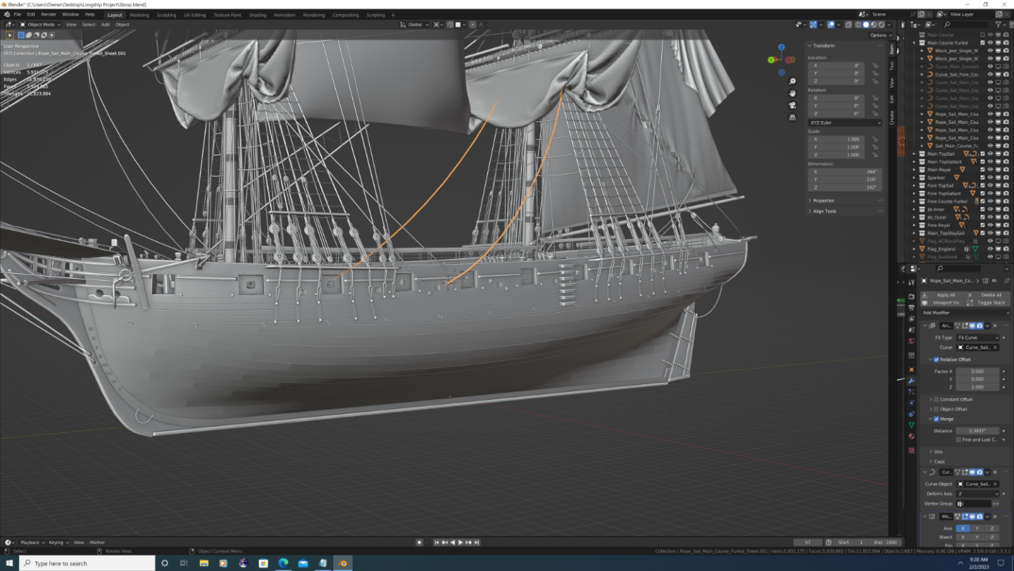
Hey folks, so I was wondering if anyone can help me identify the name of this particular line (see screenshot). It's part of the 'gear' on the course sails, and opposes the clueline along with the sheet, except it pulls the sail down and forward - so in conjunction with the sheet - the sail is pulled straight downward. I apologize in advance if I missed it elsewhere in the forum, but without the name, I had not much hope in searching for it. (BTW, is it spelled 'Clueline' or 'Clewline'? I've seen it both ways...) Thanks in advance.
-
uploading pictures
3DShipWright replied to David56's topic in Using the MSW forum - **NO MODELING CONTENT IN THIS SUB-FORUM**
Testing upload - trying to see if locally uploaded images can be expanded to full size.thumb.png.117ba5b228890127c0a70a8c03aa9b79.png)
-
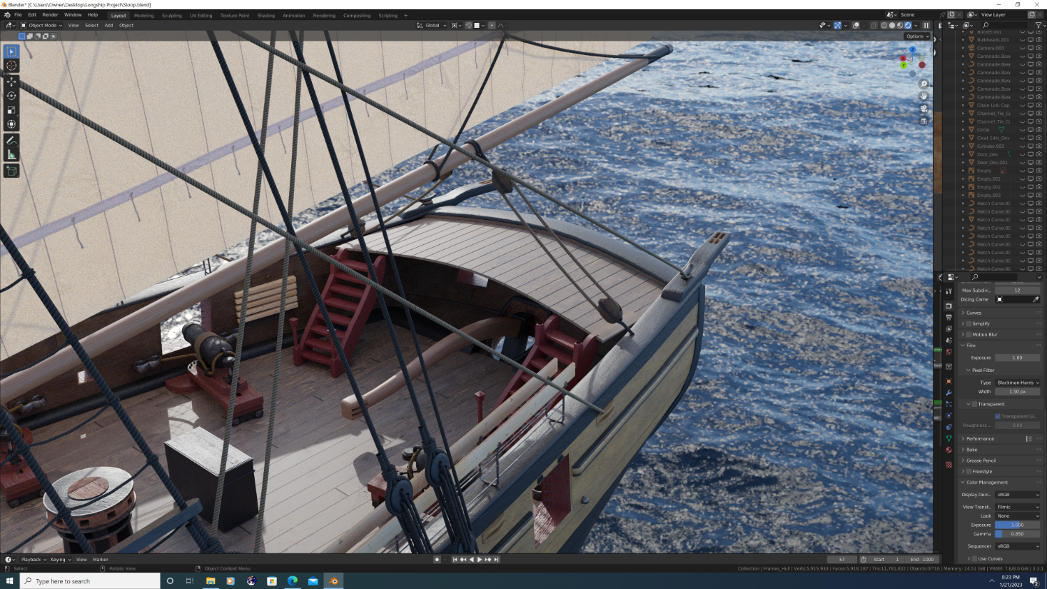
Hey Folks, So I'm almost done with the boats and I'm starting to play around with their general position in relation to the brig. Feedback welcome here: The 31 foot-long boats are rather oversized for this Brig. Thus, they don't fit cleanly behind the aft channels. I'm not willing to redo the boats at the moment - I will eventually do several Launches, Pinnaces, etc. and will swap them out when I do - so in the meantime I have to decide whether to place the davit cranes behind the channels, between the spacing of the main shroud lines (extending beyond the channels), or affix rails atop the main deck... which would mean only one boat unless stacked like Russian nesting dolls... Any thoughts?
-
Thanks guys. A couple minor updates in the meantime: 1. Knight's heads started (need to finish the caps, and reposition a couple lines of rigging). They are spaced a bit wide, but that's intentional because I'm modelling them after the style that has a stock that slides in from the top and locks the bowspirt in place. 2. Spanker Boom holster is now modelled and in place along the taff rail. Not sure why they opted to go for a double-knocked holster, but I did it precisely per the plans. 3. I smoothed out the planking near the stern where it curves the most.

-
Actually, the Belfry question is open to anyone who'd care to comment. Thanks in advance folks.
-
@Martes - Also, can you talk to me about belfry's (or the lack thereof) for a ship like this. Right now I have a bell that's floating in mid-air...
-
Yup, good observation: I actually did the lids some time ago (see image), but I think that because of the very short distance between the hinges and cap rail, this brig would require the split-style port lids that fold both upward and downward. I was holding off from further work on them until I confirm the appropriate style. Best, -Nate
-
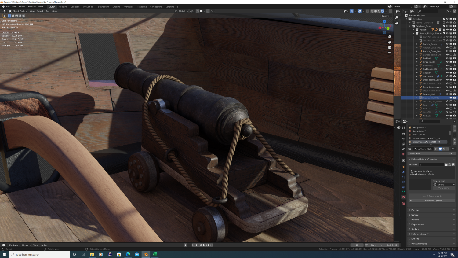
@Martes - So I checked the height of the deck, and I think it's fine. I think it may have been an optical illusion caused by the outward tilt of the stern paneling plus the fact that Carronnades sit lower than even small cannons. The image below shows a mid-sized gun (9-12 pounder based upon the bore size, carriage is the same either way) positioned as a rear chase cannon. Based upon @mtaylor's comment - I doubt whether this brig would even allow rear guns unless they were permanently fixed behind the tiller rigging, which seems unlikely. The plans also show something along the bottom edge of the stern ports, which I now believe to be mooring chocks. Anyway, based upon this info, what's your read on the deck? You think we can we call it close enough?

-
Martes makes a good point here - To clarify my post, this is precisely why you'll need the 'only smooth' option checked. Even then it's a gamble. Question: is the geometry connected? Full quad topology on the lower planking? If not, it may force your hand on sculpting.
-
First off, the hull is not bad as is, but yes, there are a few anomalies that can probably be fixed. To my eyes, you actually have dents more than bulges, but the fix I propose is the same either way. A couple more slightly more feasible alternatives than redoing the hull: 1. Use a 'Smooth corrective' modifier with 'Pin Boundaries' and 'Only Smooth' selected, placed higher up in the stack (above any sub-surf unless you're willing/able to apply the SS first). OR 2. Light sculpting, specifically the fill tool (low strength, broad radius, top-to-bottom strokes), followed by the smooth tool. General philosophy here would be expand areas first, then subtract. Again - the model still looks good in current form, so it'll be up to you to decide if the juice is worth the squeeze. -Nate
-
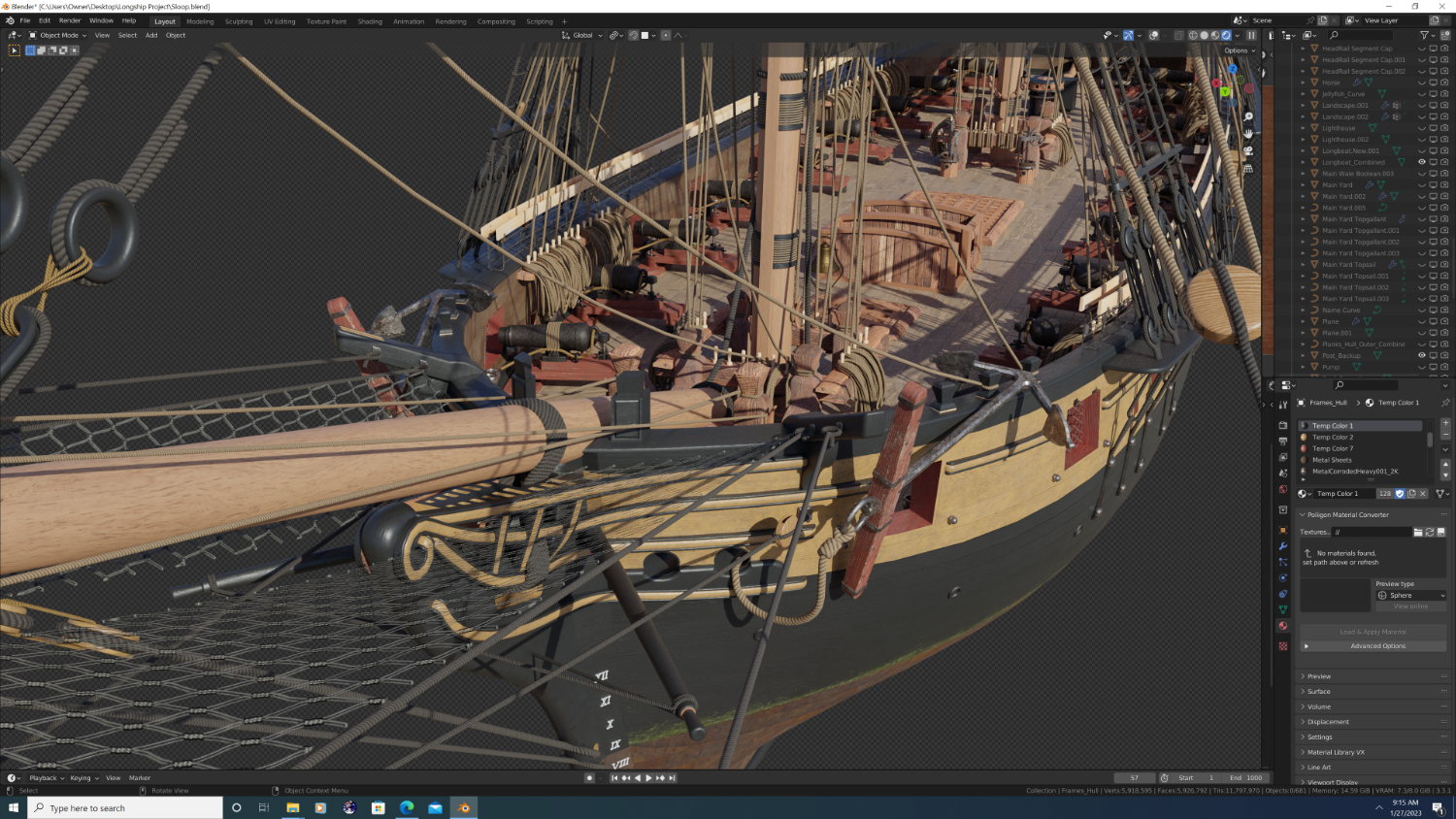
Looking great Kurtis! Not sure how you plan on doing the rigging, but as a comparative performance estimate: My brig is around 1.35Mil vertices with no rigging and 5.98mil vertices with. That said I did a few 'uber high poly' lines where I thought I may want to do closeup renders later, but even without those, I'd estimate that the total count with rigging to be about 4.25mil (currently I'm about 80% done with rigging), or about 75% of the actual mesh when all is said and done. I'm using 10-sided cylinders as in the base rope segment. If you can back that down to octagons, you'll shave 20% off the top + an exponential factor (my math is good, but not that good) when you merge duplicates caused by the segment arrays. Whatever you decide, keep up the good work! -Nate
-
Okay - I see the problem on the stern port height - and yes, it is the deck itself. I wrapped the deck in a black stringer where the deck planks meet the inner hull. While this is accurate for the sides and the bow, the stern has a series of two-three planks that quite literally curve up to where it meets the back wall. Let me see what I can do.
-
Argh - That's truly frustrating because I did it the way you described on a previous model and someone told me that the plan lines were inclusive of the planking. Now you're telling me that there's misinformation on the internet?!? Say What??? Lol - still with a maximum breadth of 30 feet 6 inches and external planking thickness of 2 inches (x2 sides) we're talking about a disparity of 4in/366in, or 1.09% - I'd hardly call that a 'severe' problem. As Jack Sparrow said, 'You need to find yourself a girl, mate!' Sincerely though, thanks for all the support.
-
So not having comprehensive documentation on a single ship or class of brig when I began (my fault, and it won't happen again lol), this project has been - since its inception - a frankenstein. Only now do I realize the monster I created asking a community of nautical historians/enthusiasts their feedback, as each person approaches this with a pre-conceived notion of a brig from a specific time period and a specific configuration. I will also say that nothing I did was pulled out of thin air. @mtaylor and @druxey - I agree that a poop deck that small may seem pointless/arbitrary, but it's not if you stop and think about it: It's elevated enough to allow the captain a vantage point without having to go aloft, and that's all it was intended to do. It's actually called a bridge deck, and sources I've read assert that it was the origin of the term 'bridge' for the command point on a ship. The USS Niagara has one and it was part of the original 1813 build. That said, I'm extending it and I will be adding deck house underneath it soon. Give me some time to incorporate your suggestions and I'm happy to take additional thoughts/comments. Best Regards, -N.
-
Yep, on it. I gotta take it plank by plank so it takes a while. I think I'm going to bring it a bit further forward still, but I'm pausing here till I build the paneled closet dividers.

-
Okay, I've stripped down the stern, only keeping the corner ornaments and the basic trim board. The rudder chain will be re-positioned once I get a general idea of how the steering rigging will go. Tiller has been modelled, but I still need to rework the back section on a large scale
-
@Martes - Ahh, gotcha! So I can incorporate a wheel if I cosmetically like the look of it (which was kind of the whole reason I did one), you're saying I just need to model the tiller on the top of the rudder as well.. Perfect, consider it done! The model you're showing is really good - Would you mind sharing a few more images of the back-end detail for reference? Any actual diagrams or dimentions of the tiller? As a general rule, if I eyeball something it comes out wrong, so i'd like to start as accurate as possible. Regarding the rudder chain, no problem - I'm using curves and the array modifier so its easy to reposition. Something felt wrong about the way I'd done it anyway, I just couldn't put my finger on it. @druxey - Yeah, as both you and @Martes have alluded to - I think I need to make a decision on whether I'm going for real or creative, historical or retro-fitted. Tell ya what - I'll first complete the model realistically and historically, then when I'm done, I'll duplicate the project and go creatively nuts! Does that work for everyone? Lol Thanks guys, much appreciated, as always. -N.
-
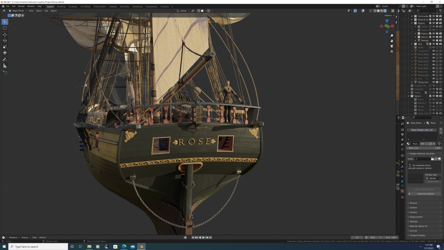
@Martes And the taff rail I did is pretty low, I think the angle of the image may have been deceptive. Here's a character in the scene for reference. She's 5-1 if that helps. Best, -N.


.png.22e820814075fd98fd1d9a7d481332d0.png)