3DShipWright
-
Posts
249 -
Joined
-
Last visited
Content Type
Profiles
Forums
Gallery
Events
Everything posted by 3DShipWright
-
Good news is this is an easy issue to solve... Your problem is that your frames are way too thin. Even when using a uniform thickness due to the solidify modifier, the thickness of the frames should be, I'd guess, no less than 8-10 inches. Start with that and go from there. Best, -Nate
-
Good point! Along time ago I simply got in the habit of ensuring any and all mirror modifiers I use go to the very bottom of the stack... that way, you can mitigate potential issues.
-
Keep in mind the boolean does leave behind a messy topology, but you can quickly clean it up by selecting all horizontal edges by selecting a couple from each part, using the select similar -> direction to get all 'intentional' horizontal edges, then press numpad 1 to select the vertices that comprise those edges, then ctrl + I to select any messy verts left over from the boolean, then finally delete -> dissolve vertices Hope that helps, -Nate
-
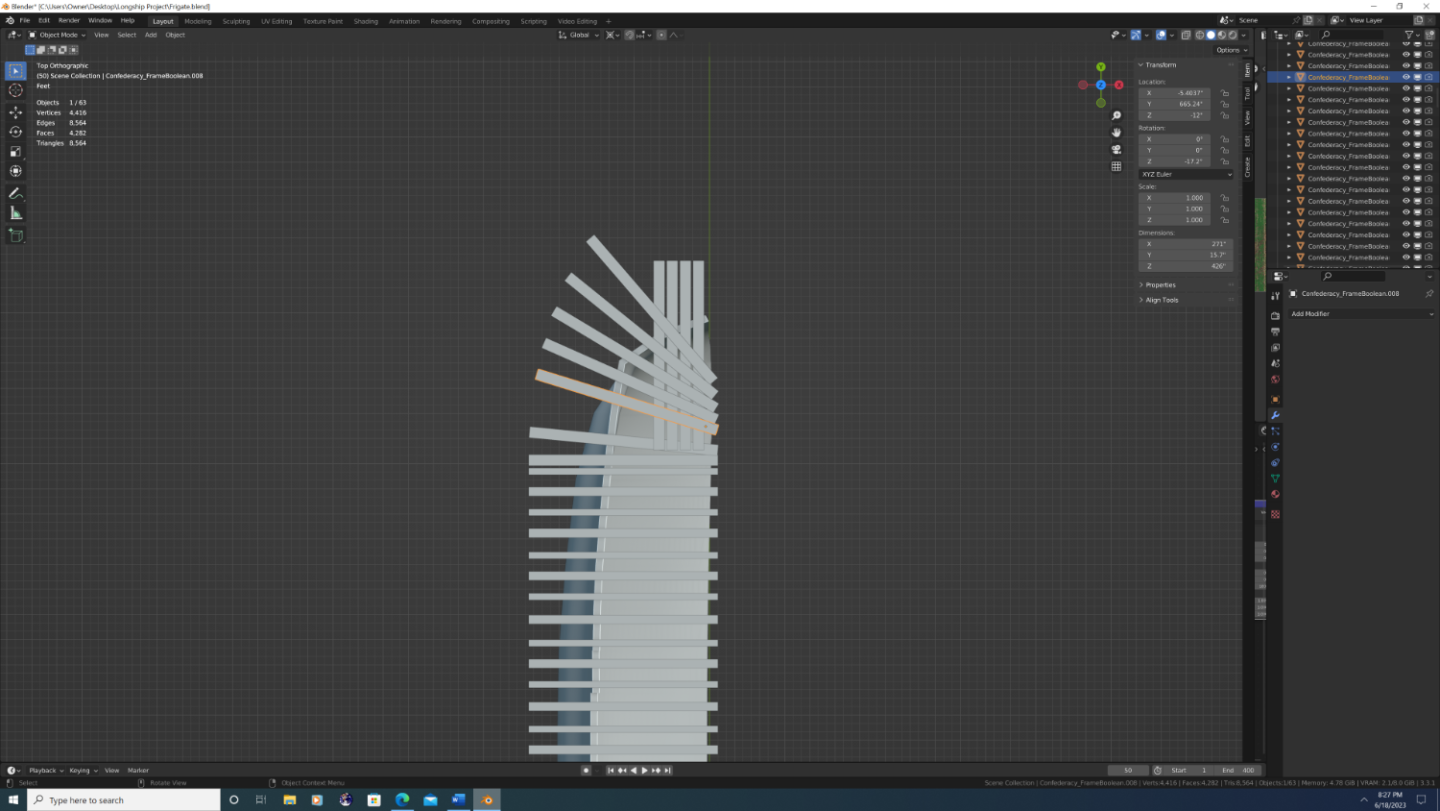
For the cant frames (or all frames for that matter), use a single solidified hull (modifier already applied), then use other objects as 'frame' cards and the boolean modifier (set to intersect) to get perfectly cut frames like so:
-
Excellent start... and yes, I extensively used all three fixes you listed above, I just didn't list them because the tutorial I made was already hard enough to follow, and I assumed anyone that could follow it would also be able to figure out the 'change direction' hack on the curve segments and how to enable the modifier views correctly in edit mode. On a side note, its truly irritating that Blender can't figure out that a series of curves that all start from z=0 on the world plane should be pointing the same direction, but oh well... I too own the AOS Pandora book, and in that book, note the complexity of the outer planking. in fact for my Confederacy build, I mimicked Pandora's hook-and-butt joints along the main wale, as well as how certain planks widen. to meet the gun ports in key spots. Anyway, great job - excited to follow your progress. -Nate
-
@Martes - Yep, agree with everything you just said, a couple things: The height of the copper plating isn't really something I can fix at this point sadly. I mean - I could of course, but it's unnecessary work given my final renders will have the ship in water. I hate to use that as an excuse, but technically speaking, Rose is already rife with problems, so I want to spend more of the remaining time on this project honing my lighting, compositing, and visual effects abilities. I have, however, sunk her down to the appropriate level in final renders. 2. The rings will be removed. When I previously said I saw these on historical plans, I now believe I was confusing modern-era dry-dock mounts with 18th century deck scuppers, which wouldn't be at that level on a small brig, if at all. 3. Finally, I will be replacing the union jack with a real Royal Navy flag from the time. The challenge is finding or color grading a texture to match the sail cloth material. Again, I can do this, but I want to finish up the rigging 1st. -Nate
-
Hey Everyone, I will be posting a major update to Rose shortly, hopefully one of the 2 or 3 final updates before I can stamp the word 'FINISHED' on the thread. That said, as I can't put Rose on a shelf in my bedroom or home office, I'd envisioned doing a series of epic renders with her, rife with special effects and postprocessing... which brings me to my question for the community: Would any 3D Artist out there be interested in doing a compilation collaboration - gotta love the alliteration - with me on a naval battle, perhaps; effectively a modern take on those classical maritime paintings I'd venture to say we all love? It will be a while, granted, but I wanted to put a feeler out there to see if anyone else would be interested... Thx, -Nate
-
@Martes - So I'm revisiting Rose a bit this morning... gotta say, thanks to yourself and others on this forum, my nautical/historical understanding has come a long way since I started this project. For example, you once asked me what the rectangular linen boxes were inside the hammock cranes as hammocks were packed into cylindrical containers... I now have the correct answer: The USS Brig Niagara, like the USS Constitution, is an operational to this day, but unlike the constitution, Niagara offers day trips to the public. Thus, she is subject to the laws of the USS Coast Guard. So, in an effort to preserve the historical feel, adult lifejackets are stored in the hammock cranes in sacks that mimic the linen of the time... A nice touch by the Pennsylvania Historical Society, if you ask me. I am still removing them from the final model, but just thought I'd share
.png.d8ab635d788db8983ae8ae3e49b6cbb6.png)
-
@Maddog Shipyards - Excellent question re: UV unwrapping... So I'll give you a few different answers/things to consider. The whole 'low-poly' concept for real-time applications (i.e. Unity, Unreal, etc.) is widely misunderstood. Keeping a low poly count is mainly important for models used in particle systems like trees/vegitation, or not letting it get to a crazy-high number in models that are complex by nature such as people and animals. Just FYI - buildings, unless you're re-creating a gothic cathedral, should be easy to keep low. Having said that, there is an argument to be made that a game that takes place on the ocean would need all environment models (i.e. boats and ships) to be low-poly because the ocean itself has to be fairly complex geometry in order to look good. Luckily, there's a very convincing work-around: The trick is to layer 2 ocean modifiers on top of each other. The first is a large scale, low-poly plane that will act as the underlying 'waves' or 'swells'. The second is a small-scale, super high-poly ocean modifier that mimics the ripples. Both are baked into a displacement map, but only the large scale displacement is used to displace geometry while the high poly is simply a bump map. The results look like this, and surprisingly - the entire ocean has far less polys than the ship itself: The 'professional' 3D workflow used by major studios is modelling -> re-topology -> UV unwrapping/texturing -> 3D rigging (not to be confused with rigging on a ship) -> animation (or baked animations - which Blender calls 'actions' - for use in video games). Professional studios have teams of people whos full-time jobs it is to do a specific step in the above workflow. Ergo, as an individual artist, I actually find it easiest to use this rule of thumb: UV unwrapping/texturing should be done in a way that prevents duplicating work. Therefore, I will hold off at least until I'm satisfied that a particular portion is finished from a modelling perspective. However there are two scerarios where you want to texture earlier in the process. they are: Things I'm going to reuse multiple times. (Example: anchors, barrels, bollards, cannons, cleats, columns, deadeyes, grates, lanterns, staircases... you get the idea) Anything that requires an array modifier. (Example: chain links and rope segments... plus maybe a couple little things I'm missing) Hope this helps, -Nate
.png.bdeb1aca556eff18a37ae182f966ee7d.png)
-
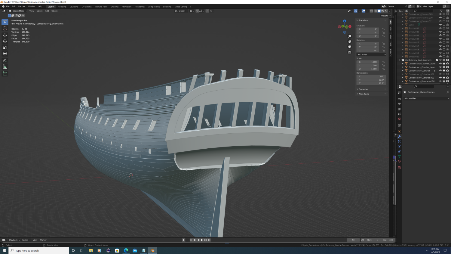
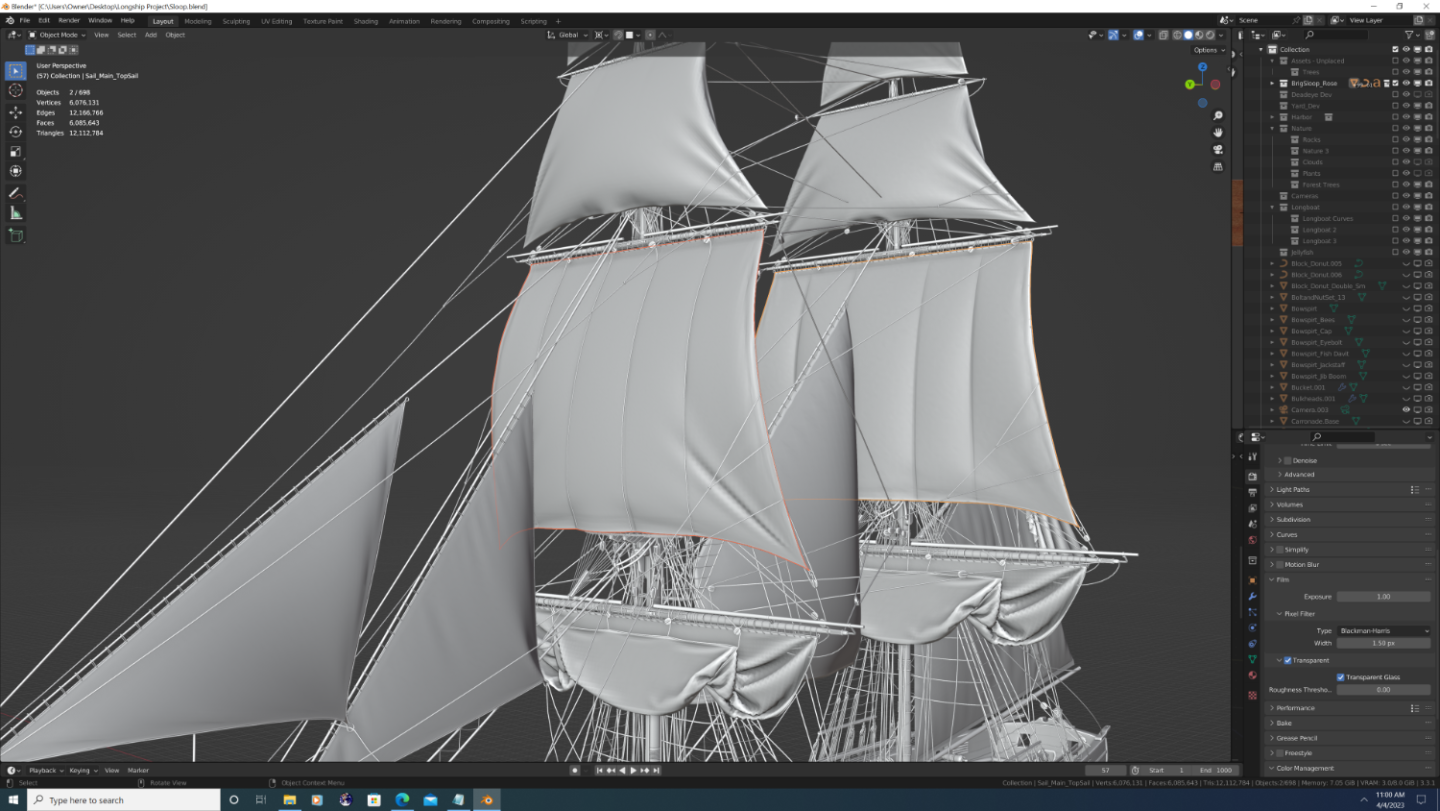
Thank you Maddog! So years ago, one of my 3D mentors once told me, "At the end of the day, there is no substitute for actual geometry." Weighing in at 6,076,131 vertices and 6,085,643 polys, Rose (a fictional brig - named after the original HMS Rose replica, titled HMS Surprise for the Master and Commander film) is proof of that idea. Even so, I think I would amend that to say, "There is no substitute for actual geometry... where it counts." As to figuring out precisely where that is, well, there in lies the rub, as they say. Best, -Nate
-
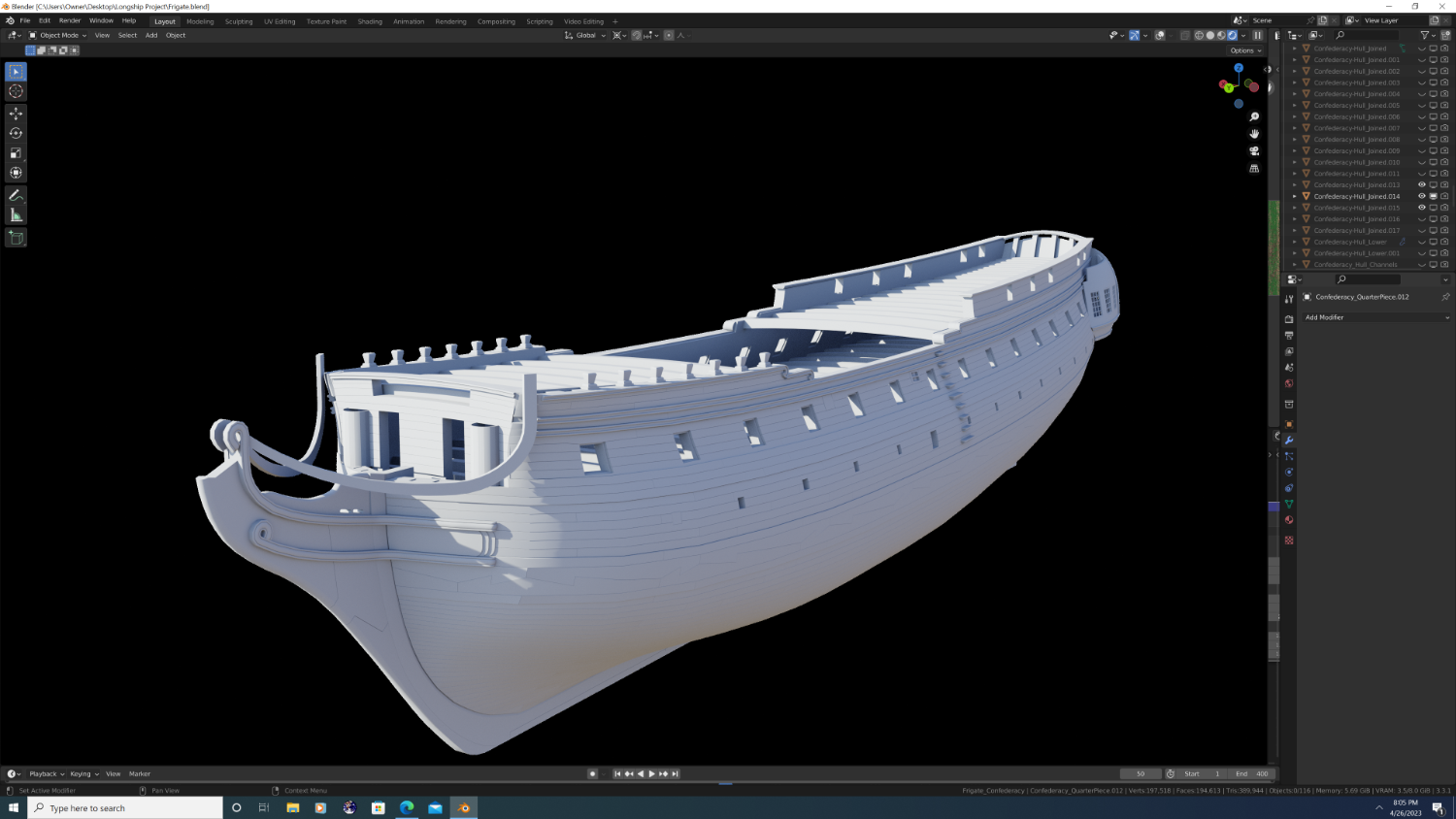
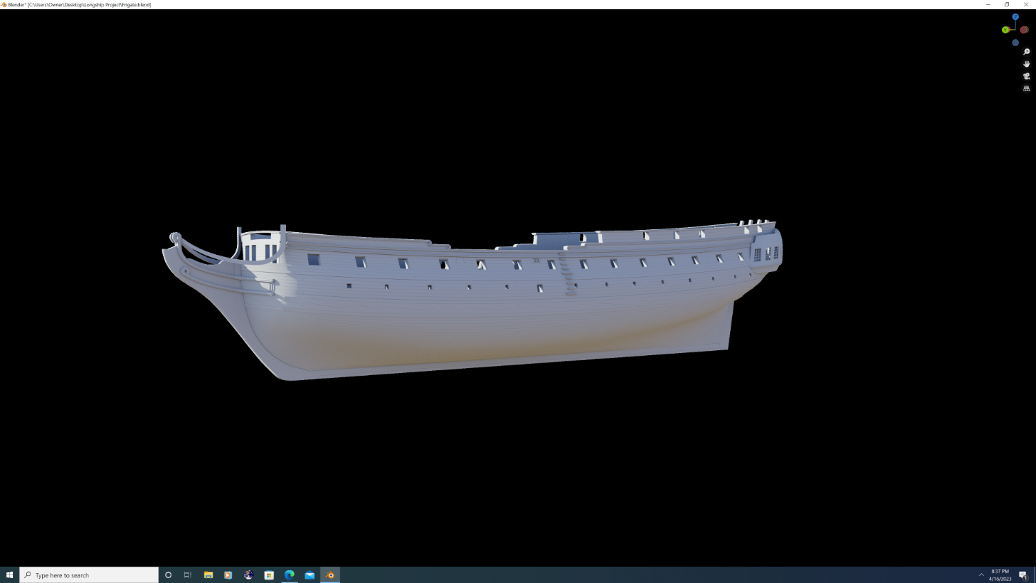
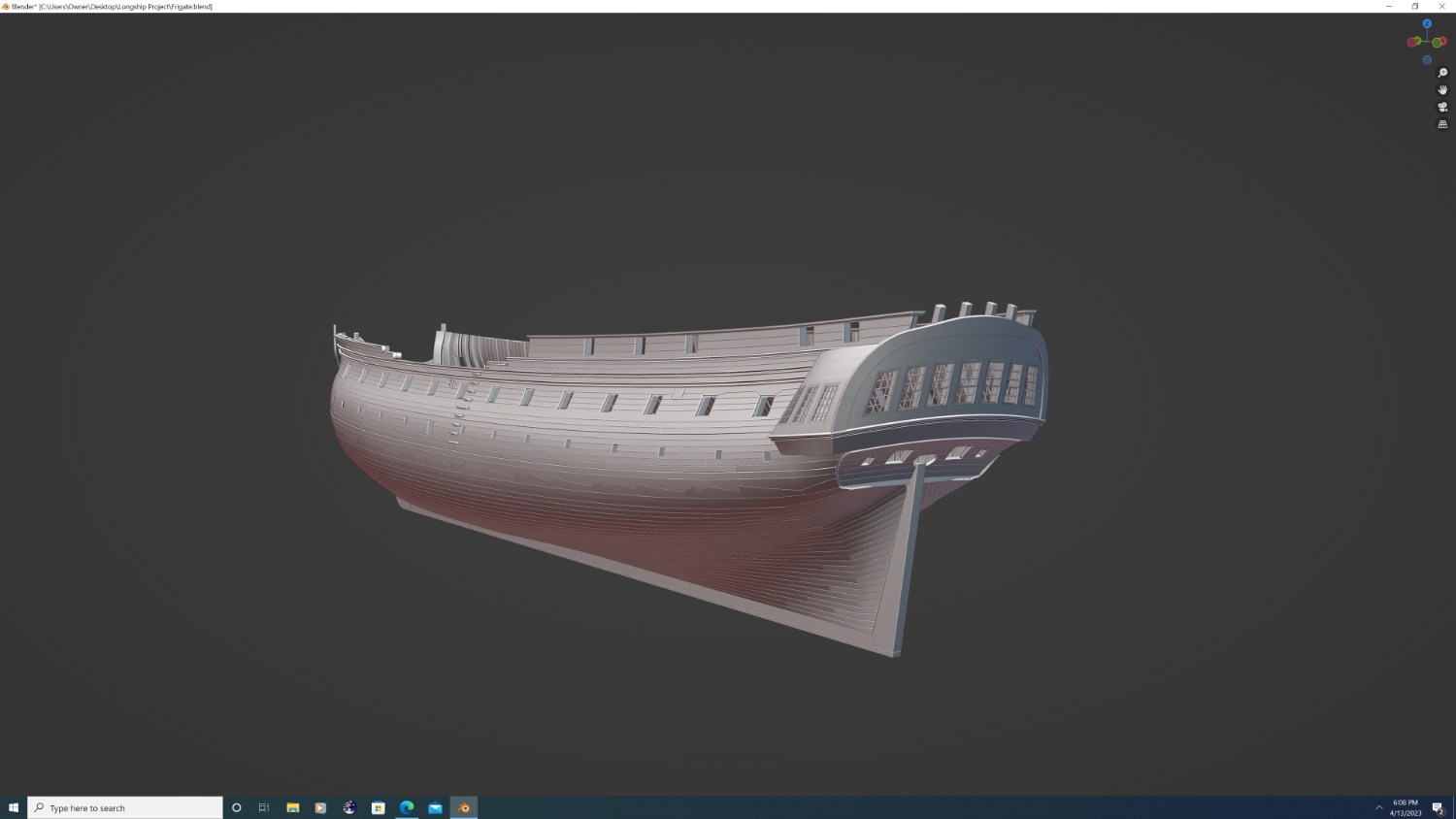
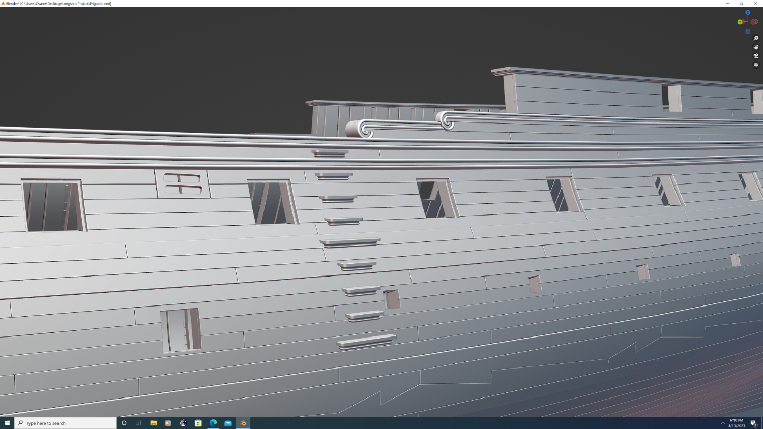
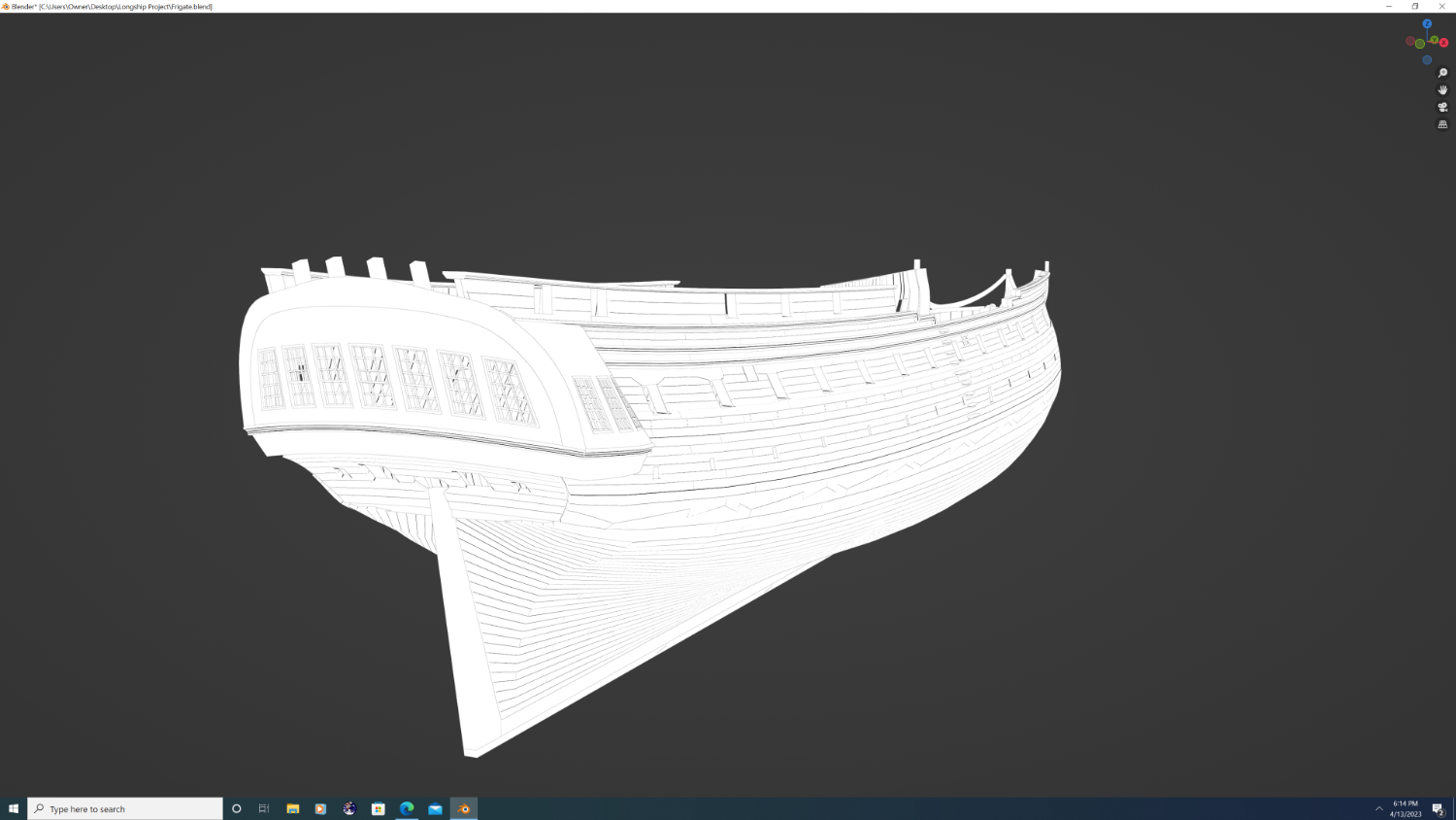
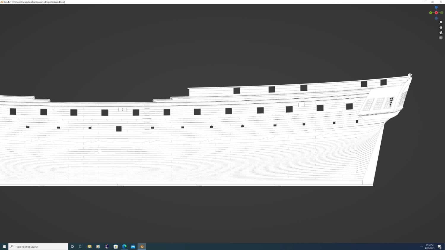
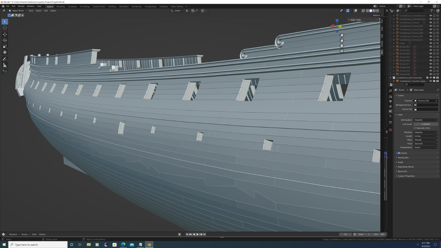
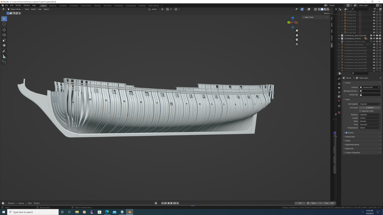
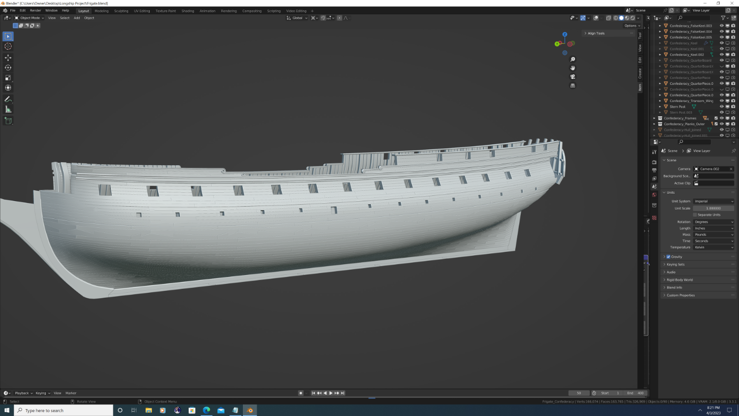
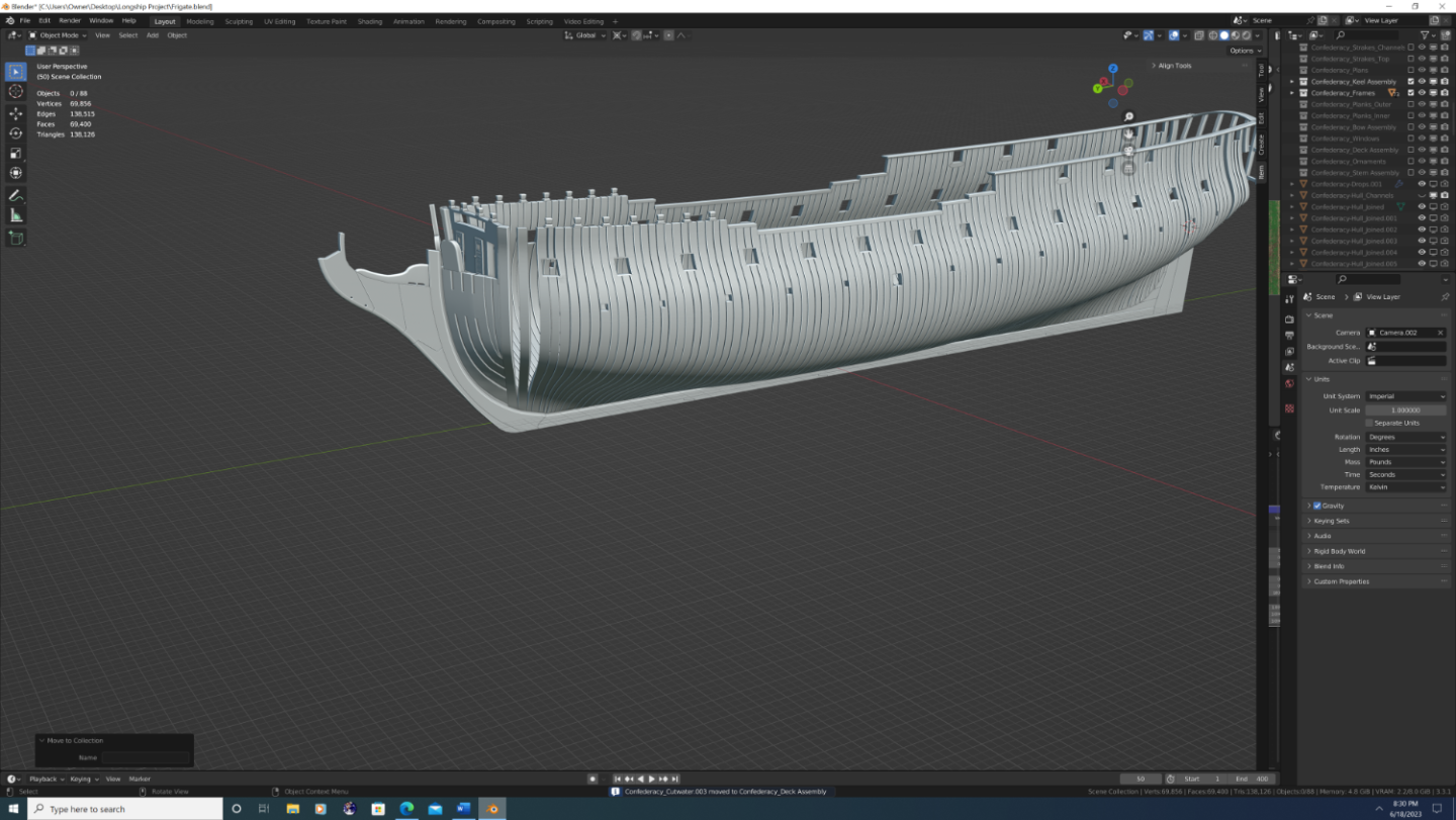
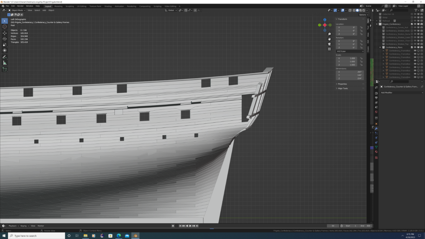
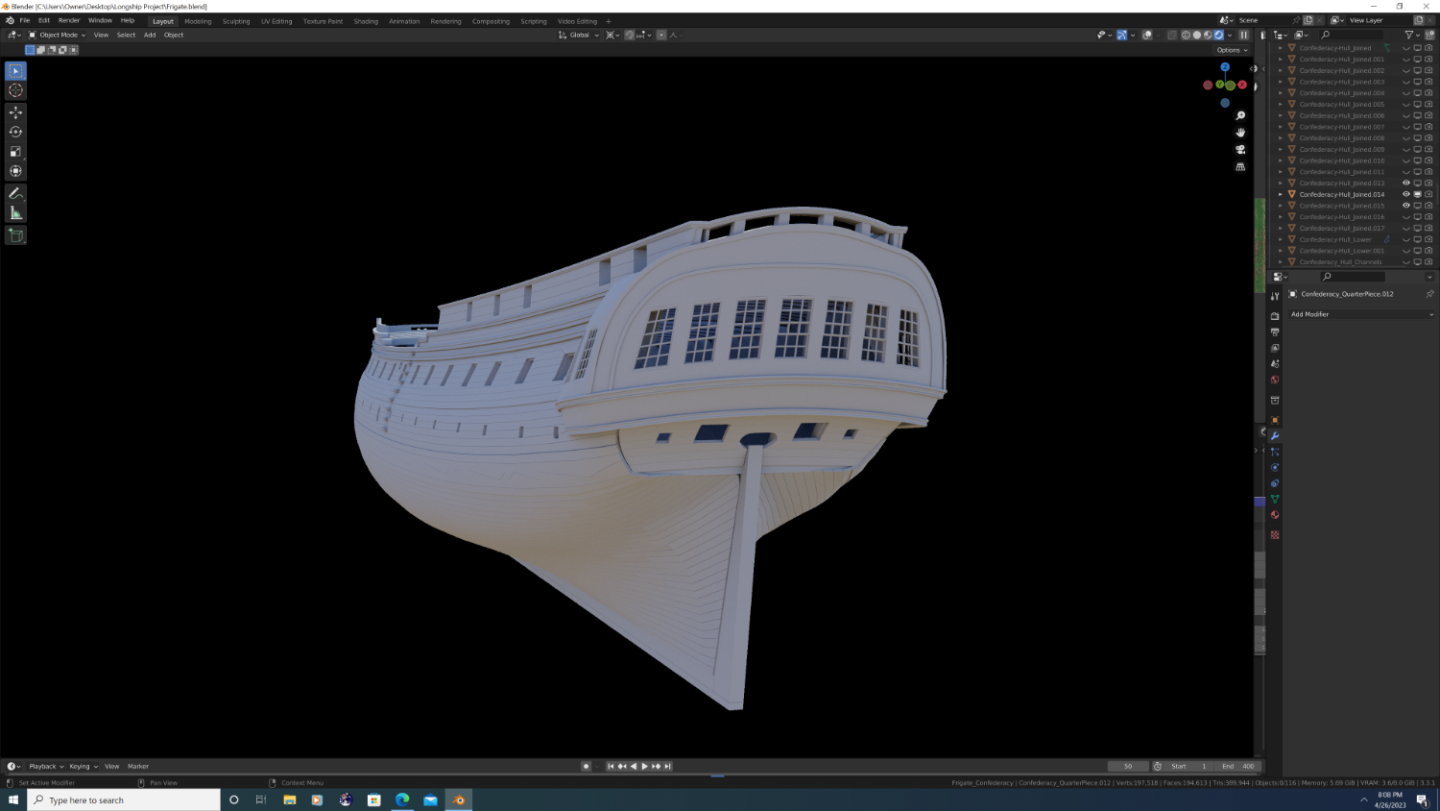
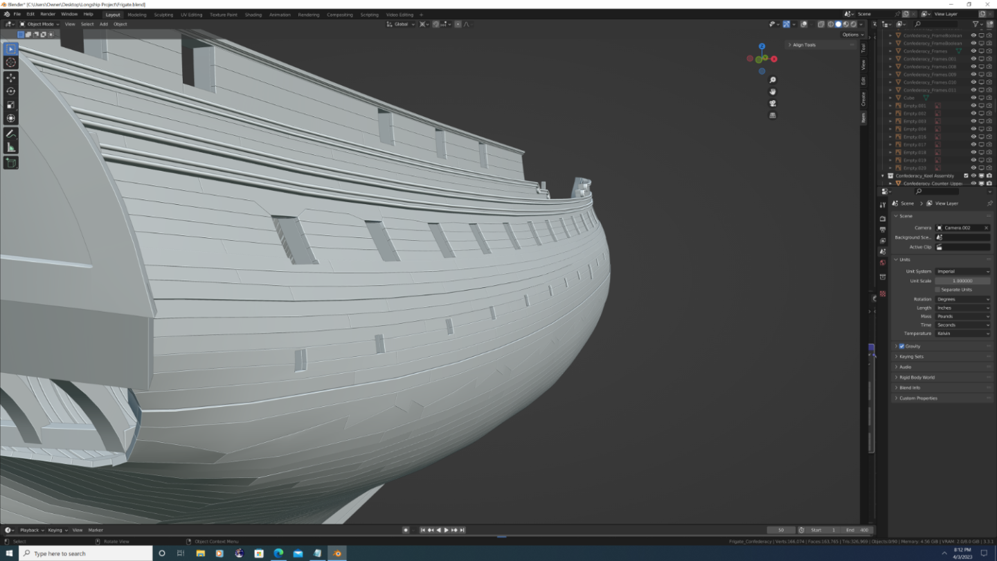
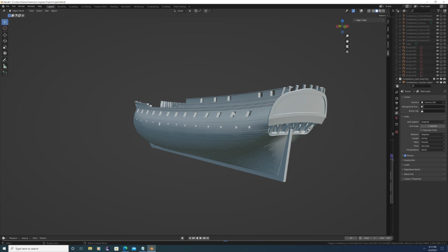
Hey Everyone, So it's been a while since I last updated, and I'm pleased to announce the project is progressing, albeit at what feels like a snail's pace. Still, here some of the more noticeable additions/developments: Knightheads modelled and placed Beakneck doors modelled and placed Bobstay separated into its own piece Covers placed atop the roundhouses Seats of ease modelled and placed inside the roundhouses Internal Planking completed from the top of the quarterdeck down through the waterway on the gun deck Breastrail modelled and placed on the aft quarterdeck behind the main mast 'Confederacy' Name displayed across the upper counter at the stern (The U.S. eventually followed suit of the British practice of not attaching, painting, or otherwise displaying a man-o'war's name on its hull, but not until 1785) Channels modelled and placed Glass added to windows Paneling placed behind window framing on the 'false windows' Catheads added with sheaves Headtimbers placed using Bezier curves (minor adjustments required) And now for the screenshots:
.png.20a25754c11106924b121204a026f74f.png)
.png.2c2cdef17872ed821ad16b0bf8278969.png)
.png.9ff469f6d0aeb93daeefe207ac9003ef.png)
.png.86481d2c34d367678373c13e98fc50ad.png)
.png.e870420c22e96b9fe9e4d71b31cffa0e.png)
- 107 replies
-
- 9
-

-
- Frigate
- Confederacy
- (and 1 more)
-
Okay - gotcha, thx. Yeah, if there's no normal, roughness, specular or bump map data to consider, my question kind of goes out the window lol. Still, it makes your work that much more impressive as at first glance I thought there was that kind of 3D interpolation going on, especially with the cannons on the lower deck(s). Thx again.
-
Looks great Martes! Random question - are you baking multiple textures into a single material for each ship? If so, is this something you have a lot of experience with? I'm ashamed to admit I've been hesitent to get into that part of blender, yet I know its an absolute 'must' if I ever want to do detailed ships in a large scale setting, be it a game, video, or render. Either way, your work continues to impress! -Nate
-
Inviting @wernerweiss and @WalrusGuy as other current Confederacy builders if they'd like to weigh in. So yes, American frigates, specifically the Confederacy - were/was quite different than anything else out there at the time. The 'why' these choices were made is actually kind of ironic. But in historical context, they make perfect sense. A few years back, @mtaylorshared an excellent link to letters of correspondence between Confederacy's shipwright and the Continental Congress that shed light on her design and build. For the life of me, I can't seem to find his post again, so I'm paraphrasing from memory here as well as some inferences I drew from the text: 1. Most 'American' (I'm using quotes because the notion of America as a country was in dispute at the time lol) shipwrights were trained in service of the Royal Navy, but when war broke out, they were cut off from the design resources and structure of the British Admiralty. This was both good and bad. On one hand, they were free to break status quo and experiment with more modern techniques, such as Chapman's works, but also the Swiss mathematicians, Bernoulli and Euler. 2. America had superior lumber (specifically species of live oak and other greenwoods), but inferior or simply less availability to copper. In 1781 the American Navy finally followed suit of the English and mandated that all military vessels be lined with copper. However, that's not to suggest they didn't understand it's importance well before that, and my guess is confederacy was intended to be sheathed. 3. Confederacy can best be described as an overly ambitious project and an un-realized dream. At a time when the American Navy had a grand total of 6 warships and a handful of repurposed sloops, the Confederacy was to be the Flagship of the new nation. She was ornate, featured dozens of hand-sculpted carvings, and was stylized in an Italian sub-set of Neo-classical architecture, known as Palladian style. 4. BUT - not only did she repeatedly run out of funding, when the build inevitably ran over schedule, she was rushed out to sea. So instead of a copper hull, she got one of white oak, poorly painted white. In the cold waters of the North Atlantic, white-bottom hulls could stave off large quantities of marine growth. However, a single trip to the Caribbean, the pesky teledo worm had bored enough holes in her hull that wood rot consumed her greenwood framing within a few months. Finally, instead of 38 large caliber guns and several carronades, she left port with 28, comprised solely of 12pdrs and 6 prds. As I promised my build of her would be as close to historically accurate as possible, I intend to show her [paraphrased] "Prepped for copper but hastily white-washed below the wale, black wale and top-section, red internal planks, a hull above the wale of 'natural ochre', trims of red, white and blue, and carvings of natural wood." That's a surprising amount of color, and means the typical yellow, black and red as seen on the MSW kit is not actually correct, but to be fair, I don't know if those letters were publicly available when they came out with the kit.
- 107 replies
-
- 3
-
-
- Frigate
- Confederacy
- (and 1 more)
-
@Martes - Ah! i see what you're saying now. So I'm not actually sure how that would've been on the confederacy. On the one hand, there was no door to the quarter galleries on Confederacy, just a carve out that went all the way back (very weird, but I verified it. Also confirmed this design feature with other MSW kit builders). Anyway, there was no overlap in the framing which would require those windows to be fake so it could very well have been real glass. The USS constitution is actual glass, and accommodates a seat of ease. That said, it has a much boxier hull, whereas Confederacy looks more like the plan of L'Africane listed above. On the other hand, Confederacy also had near floor-to ceiling windows across the stern (Colonial Palladian Architecture style, a precursor to the federalist style of 1785) which would be tricky to fit a seat of ease. So short answer is I don't know lol
- 107 replies
-
- 1
-
-
- Frigate
- Confederacy
- (and 1 more)
-
@Martes - Interesting... So there's no glass in any of them yet, but are you saying the outer ones are essentially 'open air' windows, or that the framing has a solid wood sheet behind it (as seen on the Black Pearl in the Pirates of the Caribbean movies)?
- 107 replies
-
- 2
-
-
- Frigate
- Confederacy
- (and 1 more)
-
Roundhouses, bollards, taffrail in place. Quarter Pieces fixed.

- 107 replies
-
- 5
-
-
- Frigate
- Confederacy
- (and 1 more)
-
Main head rails, cheeks, bolster plates, and the beakneck bulkhead (love saying that, lol) in place.

- 107 replies
-
- 5
-
-
- Frigate
- Confederacy
- (and 1 more)
-
I've got the general 'stencil meshes' for the upper/lower counters in place. A couple errors to be sure, but by and large a vast improvement over the original version I did, for which I basically said "screw it" and just randomly shaped the mesh until it was smooth. All the pretty decoration and textures will come later, but you gotta build a house (or an 18th Century frigate) on a sturdy foundation... something I didn't do the first time around... Here's two comparative shots just for fun: New Version (so far): Old Version:

- 107 replies
-
- 5
-
-
- Frigate
- Confederacy
- (and 1 more)
-
Actually, Looking more closely at your model, I think the middle of your sails is billowed believably - its just the edges that look wrong. I would add the side edges of your sail mesh to the pin group you used in the cloth simulation, but at a low vertex weight. I think I used 20% for the outer edges and 10% strength for where the buntlines fall on the sail (on the sails that have buntlines, that is). Doing so will also give you that iconic 'segmented' look.
-
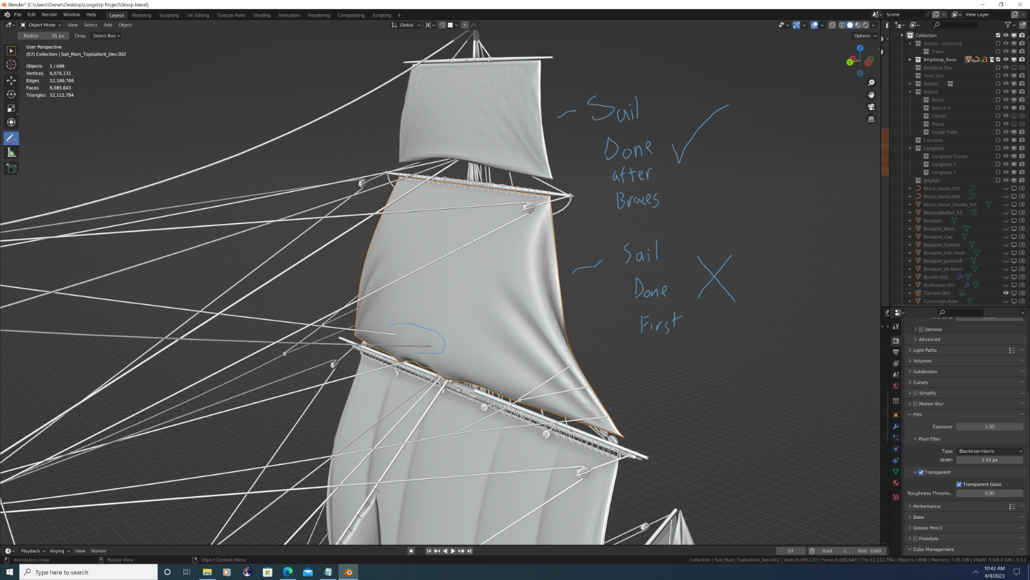
Hey Kurtis, Sorry for any confusion. There are two reasons behind my comment, but they may or may not apply to your model: 1. The braces can interfere with the sail just above its belaying point on the mast (see screenshot). In real life, you'll notice the bottom edge of certain sails will fall over the occasional brace or stay. If you do the braces first, you can use them as collision objects to achieve this effect... 2. If hardware performance is a concern and you have to make sacrifices, favor the running rigging to the yards over details on the sails... I've seen hundreds examples on CGTrader and TurboSquid where the artist favored the sails and neglected the lifts, halyards and braces. When they do this - no matter how good the sails look - the result always feels cartoonish and hollow (IMHO). If you can do both - Great! But I promise you, Braces and Lifts are far more important overall than modelling individual gasket and gromet ties. Other than that your approach is correct. When it comes to how sails interact with the gear rigging: Do any physics simulations on the sails first, apply the modifiers, then duplicate the sails to derive the curves of the lines that interact directly with the sail. Also keep in mind that on a ship of the line, the combined surface area of cloth is in excess of 40,000 square-feet! Ultimately, that makes each sheet extremely heavy, and unless your ship was in the middle of a hurricane, there's no way the sail could be that billowed out.

-
Hey Kurtis, Good update overall. So it's your decision of course, but I'd strongly recommend you pause work on the sails until you have the main components of the running rigging completed. So you know, most real-world sailors and historians I've watched or have spoken with compartmentalize rigging into three categories: Standing Rigging - The Standing Rigging structurally supports the Masts and Bowspirt. Includes the Shrouds, Stays, Backstays, Preventer Stays, Channel Ties, Crow's Feet, etc. plus some hardware such as the Deadeyes (plus lanyards), Chain Plates, and a few other misc. items. You have this modelled/installed for the most part so I won't dwell on this part Running Rigging - The Running Rigging is the set of lines used to move the Yards. These are the Braces, Lifts, Halyards (slings for the course yards), Throat Halyards (with parrels). This is where I'm suggesting you focus next, if possible. The 'Gear' - While technically part of the running rigging, the Gear is a layman's term used to differentiate the rigging that controls the Sails themselves. Includes the Buntlines, Bowlines, Clewlines, Sheetlines (Sheets), Tacklines, and Reef Tackles. While this is important in real-life, in a 3D model, you can omit much of this and still have a convincing ship Hope this helps, keep up the great work. P.S. Maybe I missed it, but had you landed on a final color/texture scheme yet? Just curious... -Nate
-
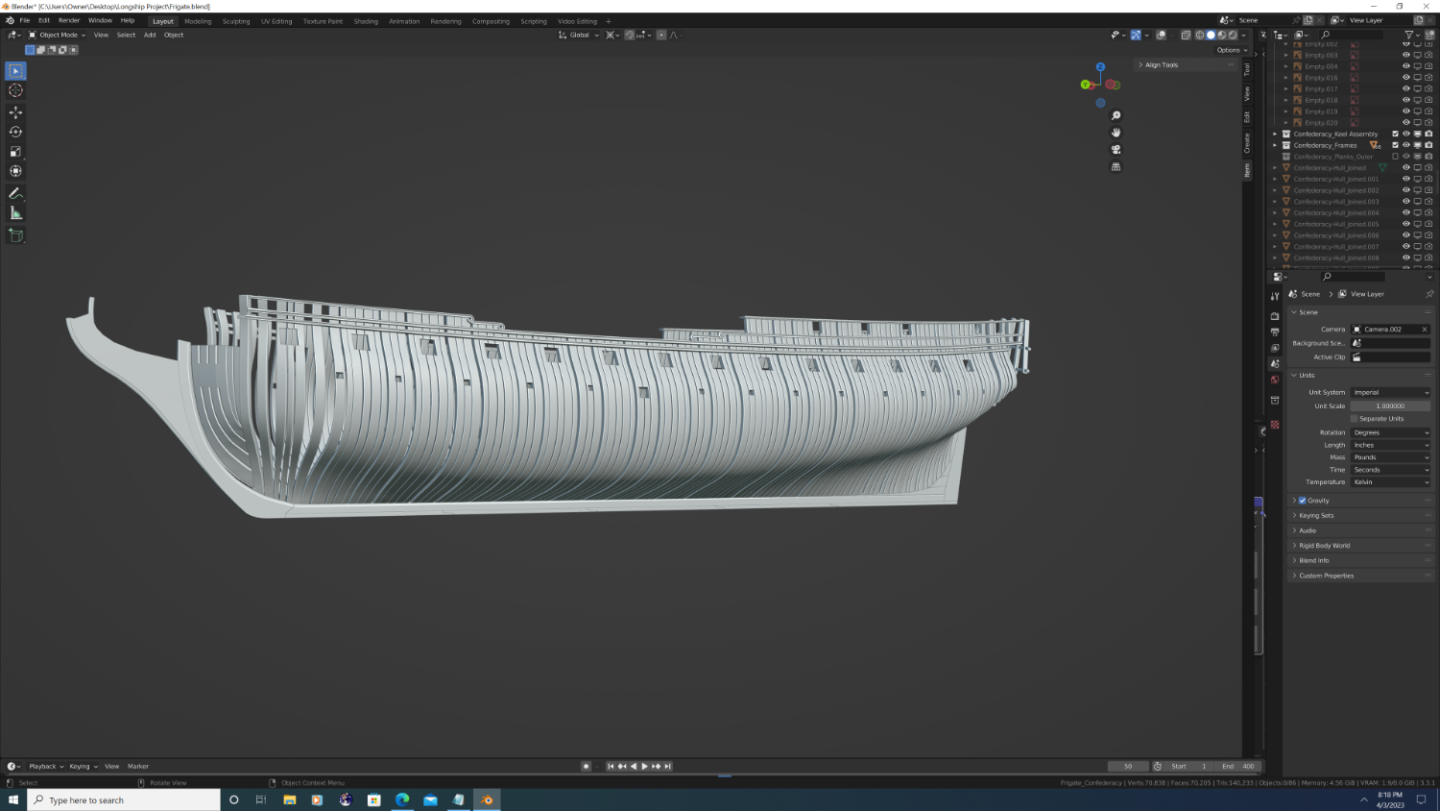
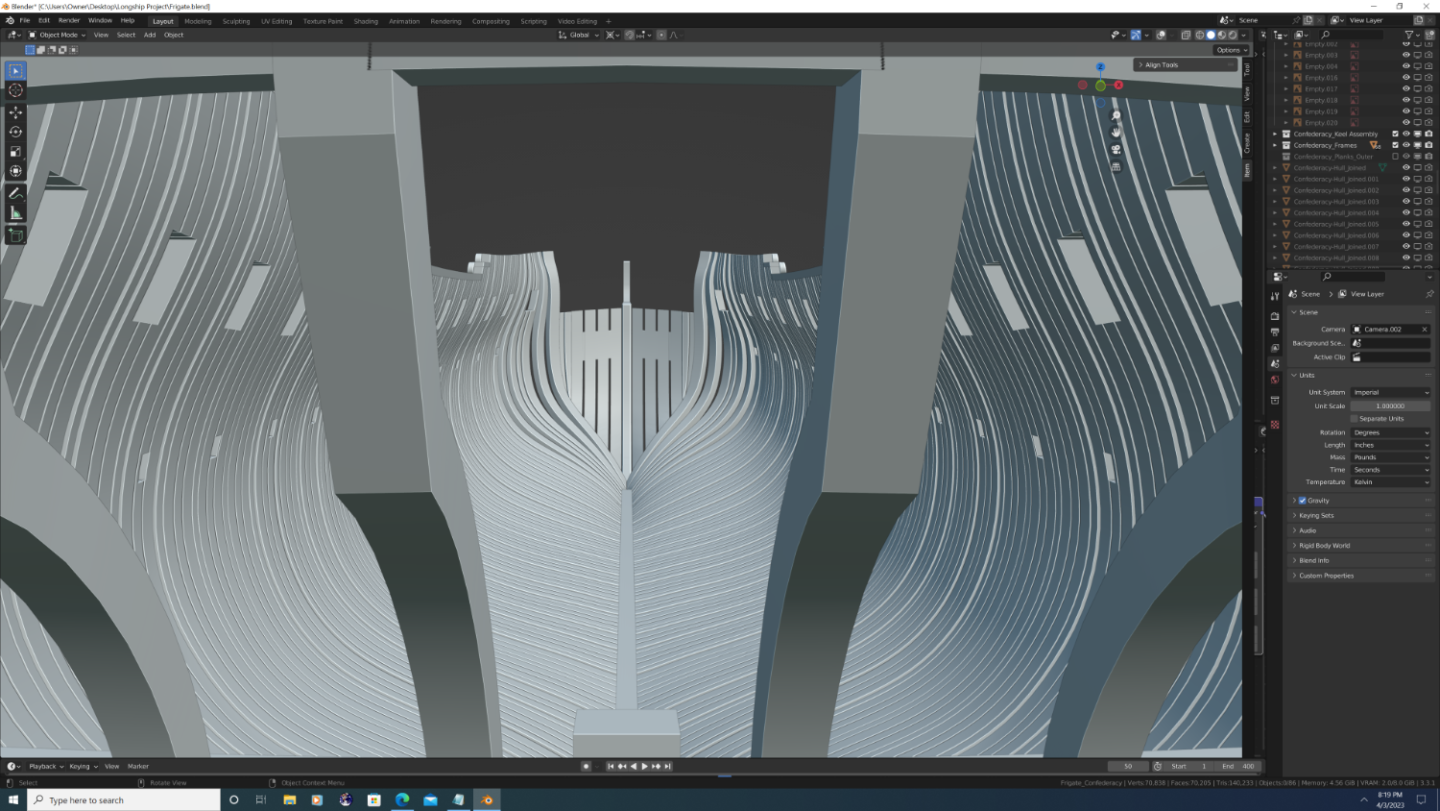
Well, it's been 1 month to the day since I started Confederacy. Framing 90% Complete Outer planking of the main hull complete! Starting the Quarter Board and Quarter Piece.


- 107 replies
-
- 5
-
-
- Frigate
- Confederacy
- (and 1 more)