3DShipWright
-
Posts
249 -
Joined
-
Last visited
Content Type
Profiles
Forums
Gallery
Events
Everything posted by 3DShipWright
-
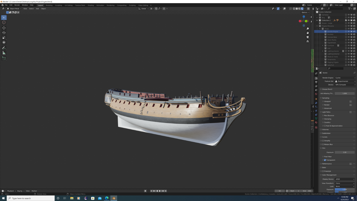
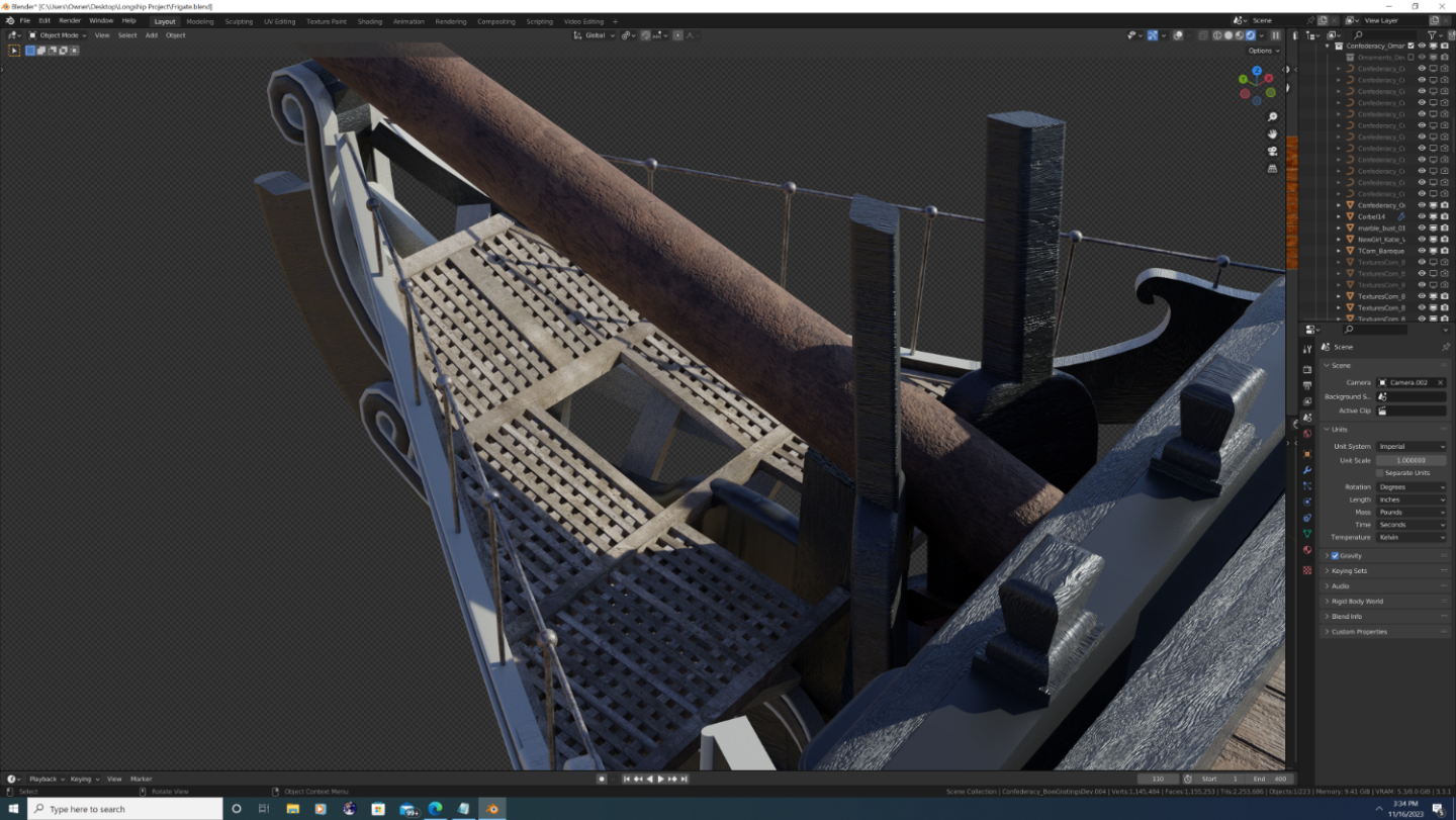
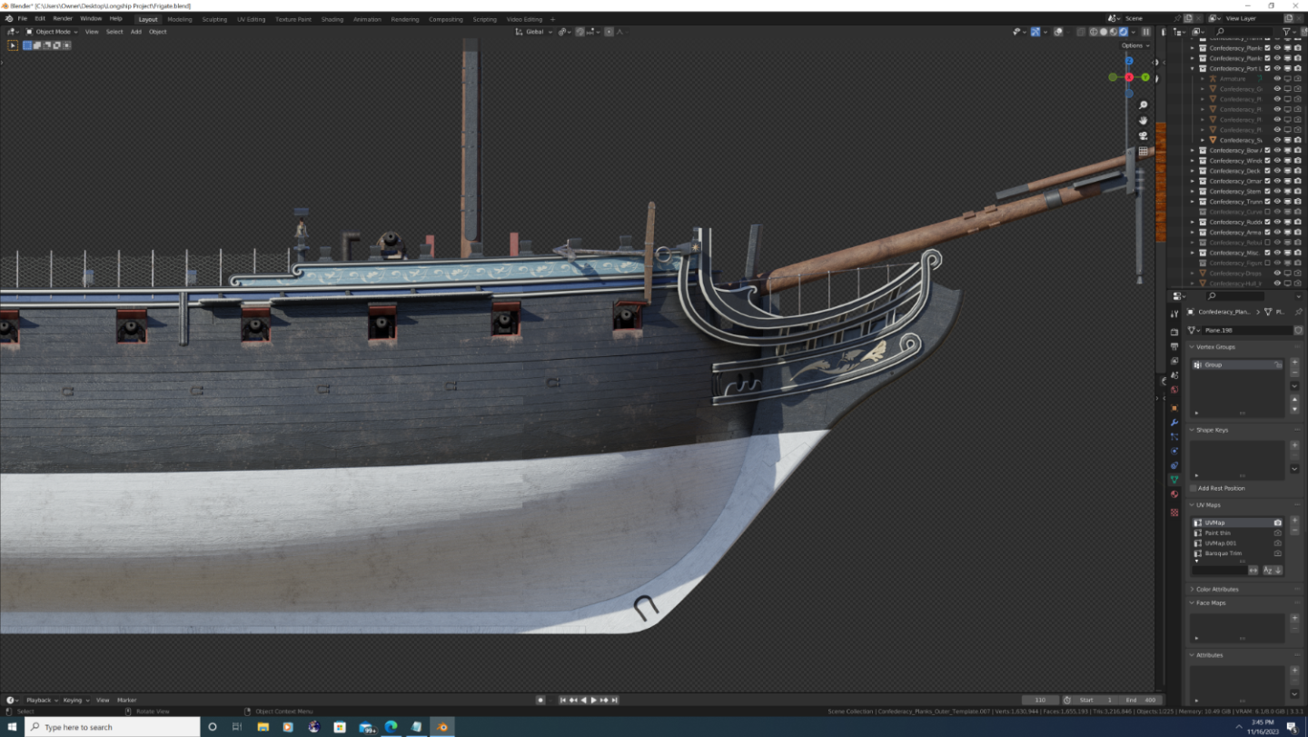
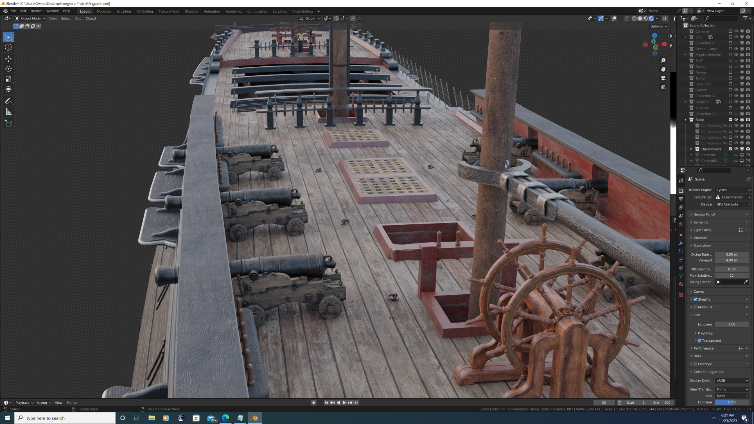
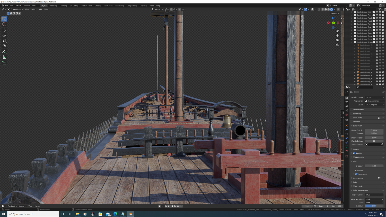
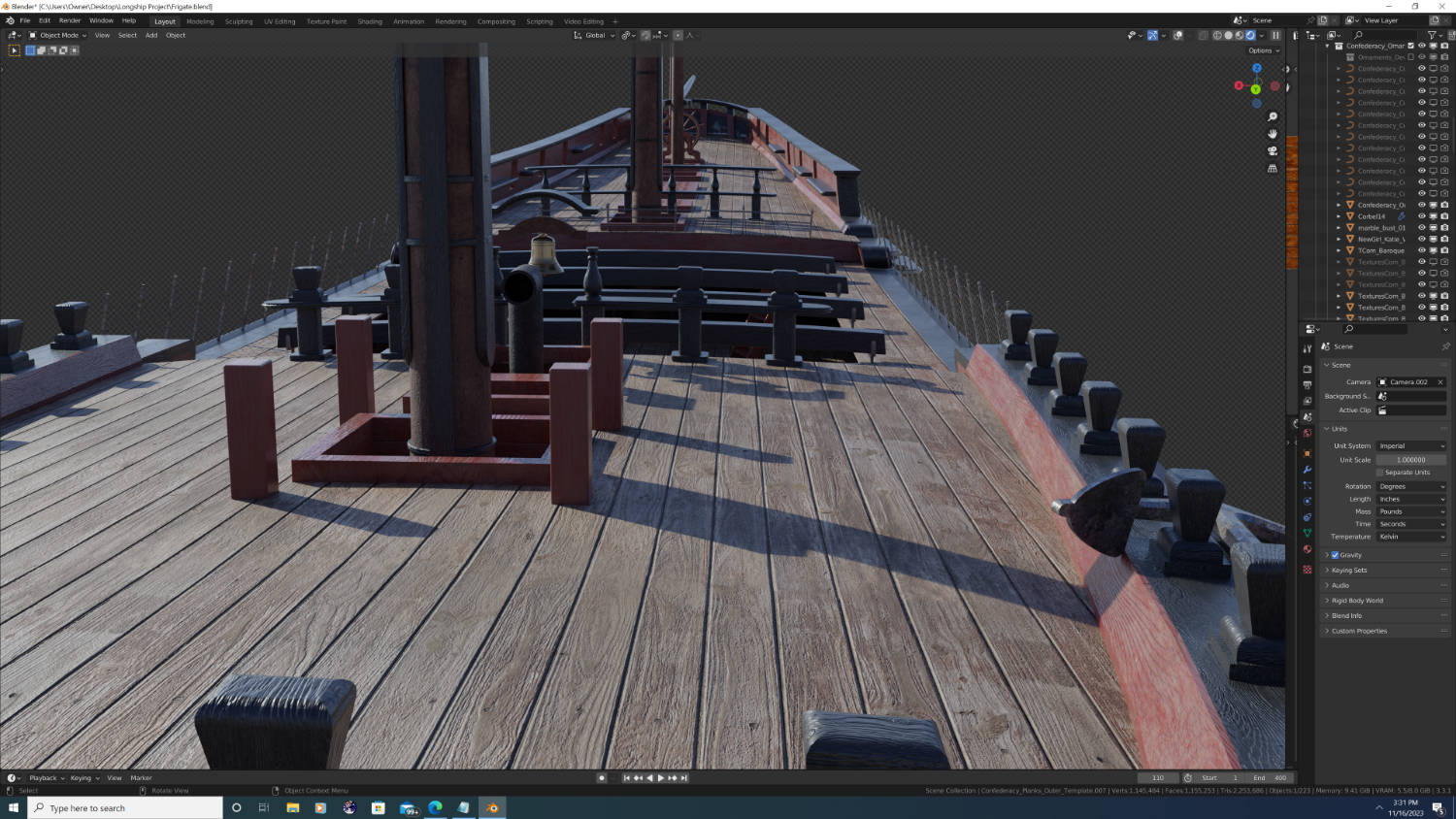
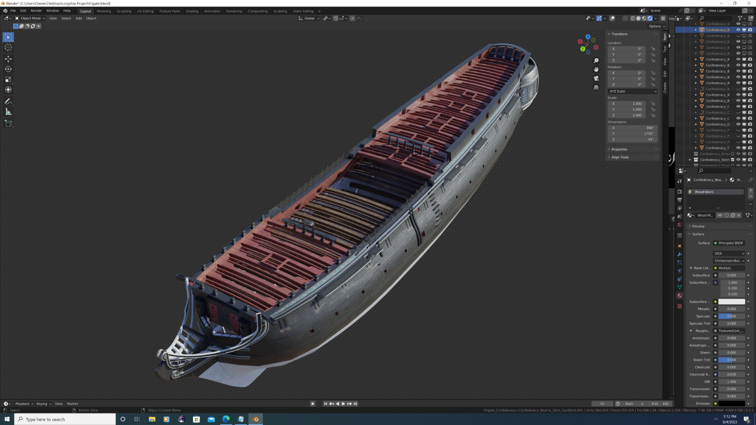
Hi @Martes, Both the masts and the grating are correct. 1. with regards to the grating - not all ships had rounded grates. This is especially true of American frigates, as I can't find one ship built in this period that did have rounded grates. I did chamfer the edges in a bit; like i said in my last post, I'm not quite done yet 2. With regards to the openings around the masts, these too are accurate. The standing rigging that belays to the eyebolts at the base of the masts are on the gundeck on Confederacy and others, not the quarterdeck. See image below, and please note: I haven't even started on the gundeck yet, I'm working top-to-bottom going through the quaterdeck, gundeck, berthing, orlop, and finally, the hold. Best, -Nate

- 107 replies
-
- 4
-

-

-
- Frigate
- Confederacy
- (and 1 more)
-
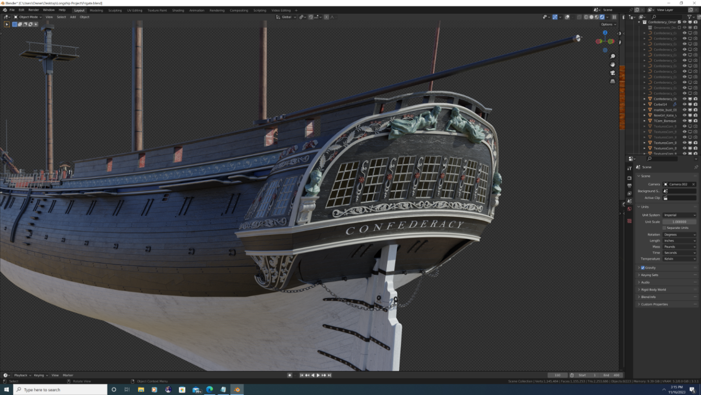
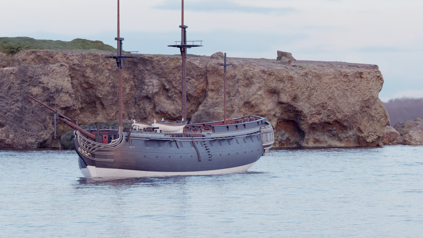
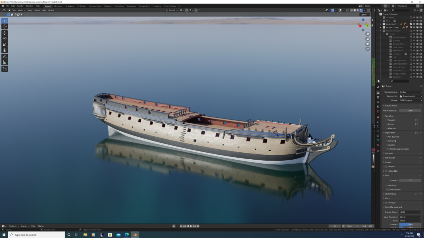
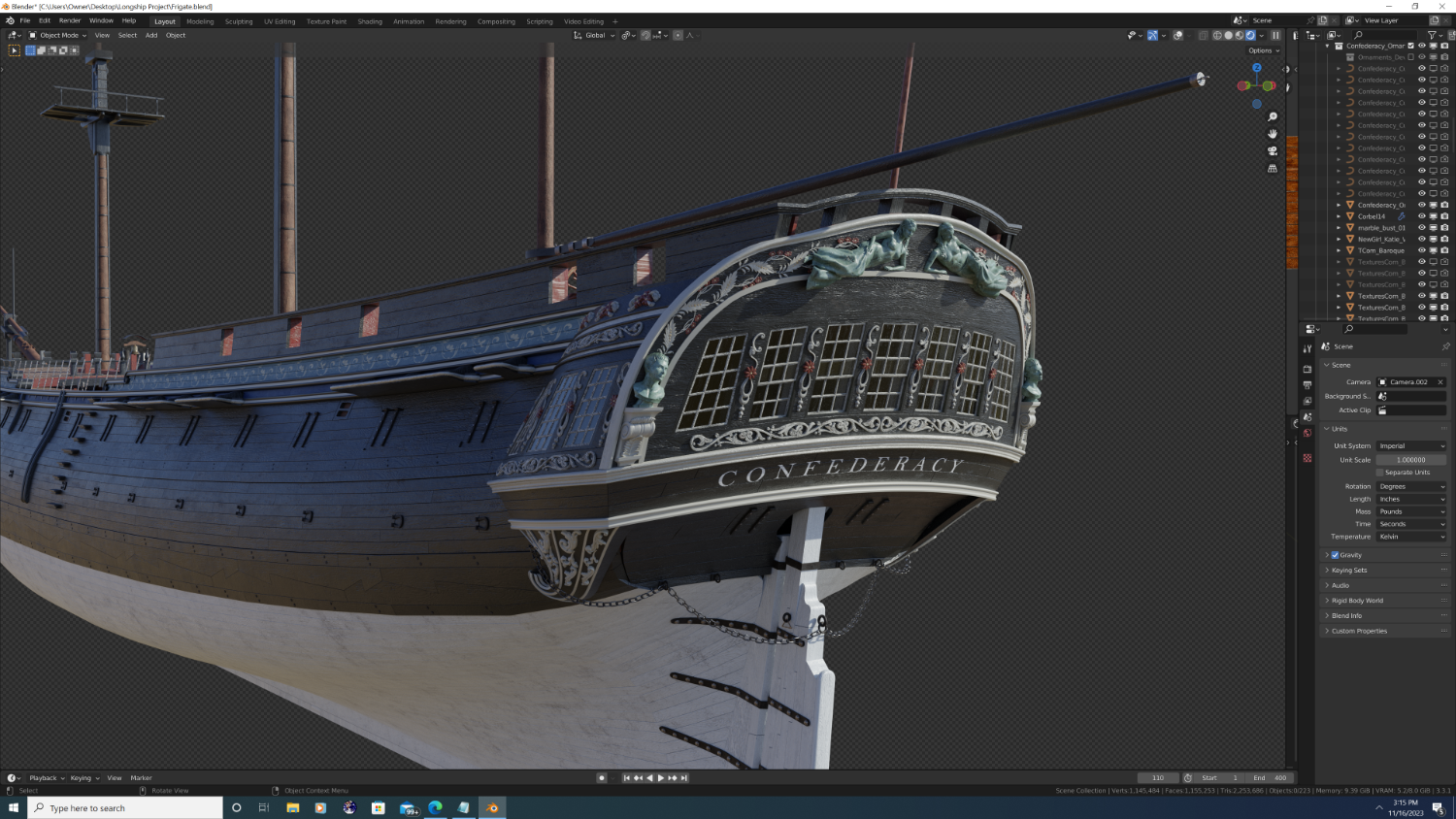
Another quick shot of Confederacy. I'm definitely liking the colder mood / lighting - what do you guys think?
- 107 replies
-
- 5
-
-
- Frigate
- Confederacy
- (and 1 more)
-
So setting aside programs, platforms, or OS for a second, making a true nautical simulation of a sail-powered ship would require a fundamentally different approach within any gaming engine, and here's why. Normally in a game/simulation, the hero character (a vehicle/vessel in this case) is setup to move through the world and actively interact with the environment. In the case of flight simulator, for example, the player controls the throttle, and once airborne can control the drection of travel in three dimensions. The same can be said of driving simulators in two dimensions (plus rise and fall of the terrain). Yes, physics impose rules - you can crash a car or stall an airplane - but it is still the player who is fundamentally in control of the vehicle. In a sailing simulation, the controls would need to be reactionary. you would start with an environmental factor, wind, and a given compass heading between 1 and 360 degrees. Then you would assign a maximum speed that a vessel could reach if all 'critera' are met. The nuances of all these 'criteria' are where this gets unbelievably complicated, and is why I believe that no studio has gotten it right. But lets say we were so inclined to be the first. The simplest scenario would be a single square-sail vessel and a yard that auto trims and a wind at a constant strength/direction. (like a viking longship). The movement logic would be something like: Actual speed = max speed [12 knots] * (1 - (vessel rotation [z-axis] / max crosswind component [wind rotation, z-axis +/- 90 deg])) And that is the simplest relationship I can think of. It all makes my head hurt lol.
-
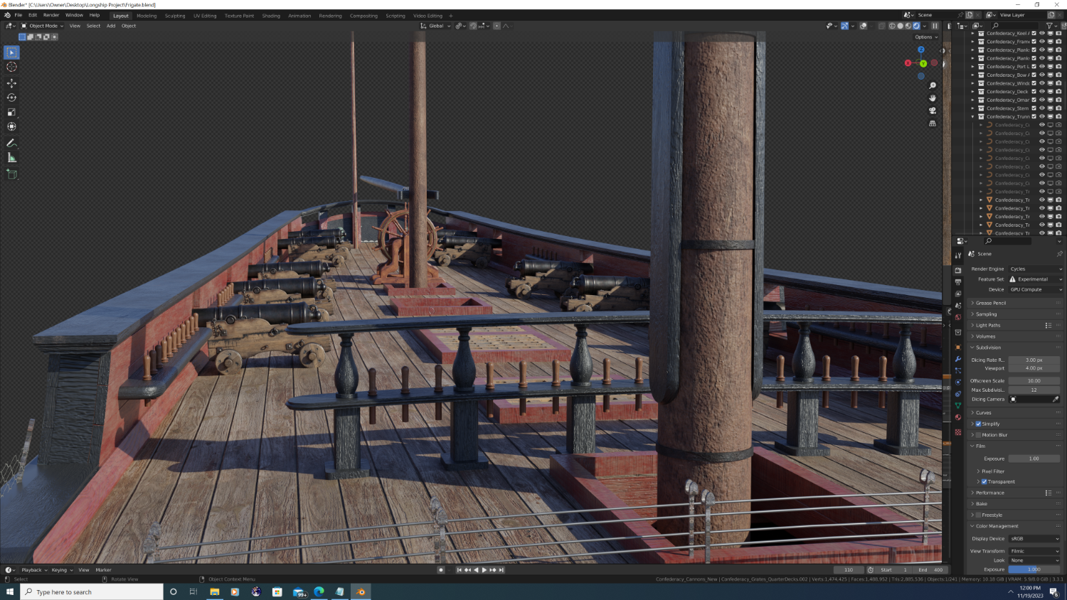
Now that's a bit more like it! - New Cannons (no rigging yet) - full transparency, they are not mine, got them from polyhaven.com (no affiliation). The model is not perfect: the carriage tapers the wrong way, the front and back wheels are the same size, and the barrel is oversized so it looks like a 32pdr gun is sitting atop a 6pdr - 9pdr frame. Still, the texturing is so good I'm going to use them anyway and correct what I can. - Jeer bits added on the forecastle - Belfry completed - Pins added to rails and jeer bits I still have some work to do on the quarterdecks, but the next images I share should be more or less the finals, without rigging that is, and barring any mistakes. For anyone who may be interested, my upcoming workflows are: - Place the iron deck rings that support the cannon rigging - Cut sheaves into the foremast jeer bits, the forecastle barricade and the breastrail barricade - Add the mizzen jeer bits, pin rail, and pins - Create the drainage holes on the quarterdeck planking for the pipe scuppers (which will come later) - Finalize the grating on the aft quarter deck (i.e. taper and bevel the footing) - Model the stand upon which the helm rests, including the crossbeams with sheaves for the rigging that connects the drum to the gooseneck pulleys. - Add addl planking inboard of the quarter piece beneath the taff rail. (I believe this part was also double planked, but I don't know for sure) - Place rigging cleats where appropriate. Best, -Nate


- 107 replies
-
- 5
-
-
-
- Frigate
- Confederacy
- (and 1 more)
-
Excellent work, as always Martes. Seeing your ships together in the game makes me yearn for a AAA developer to make a game like this using modern techniques and graphics - and, here's the kicker, make it well! I spent a couple hours this morning re-playing AC Black Flag, and it made me cringe at the direction both Naval Action and the upcoming Skull and Bones have taken... But I digress... keep up the good work.
-
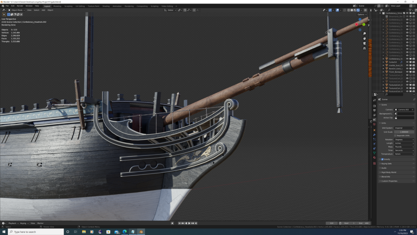
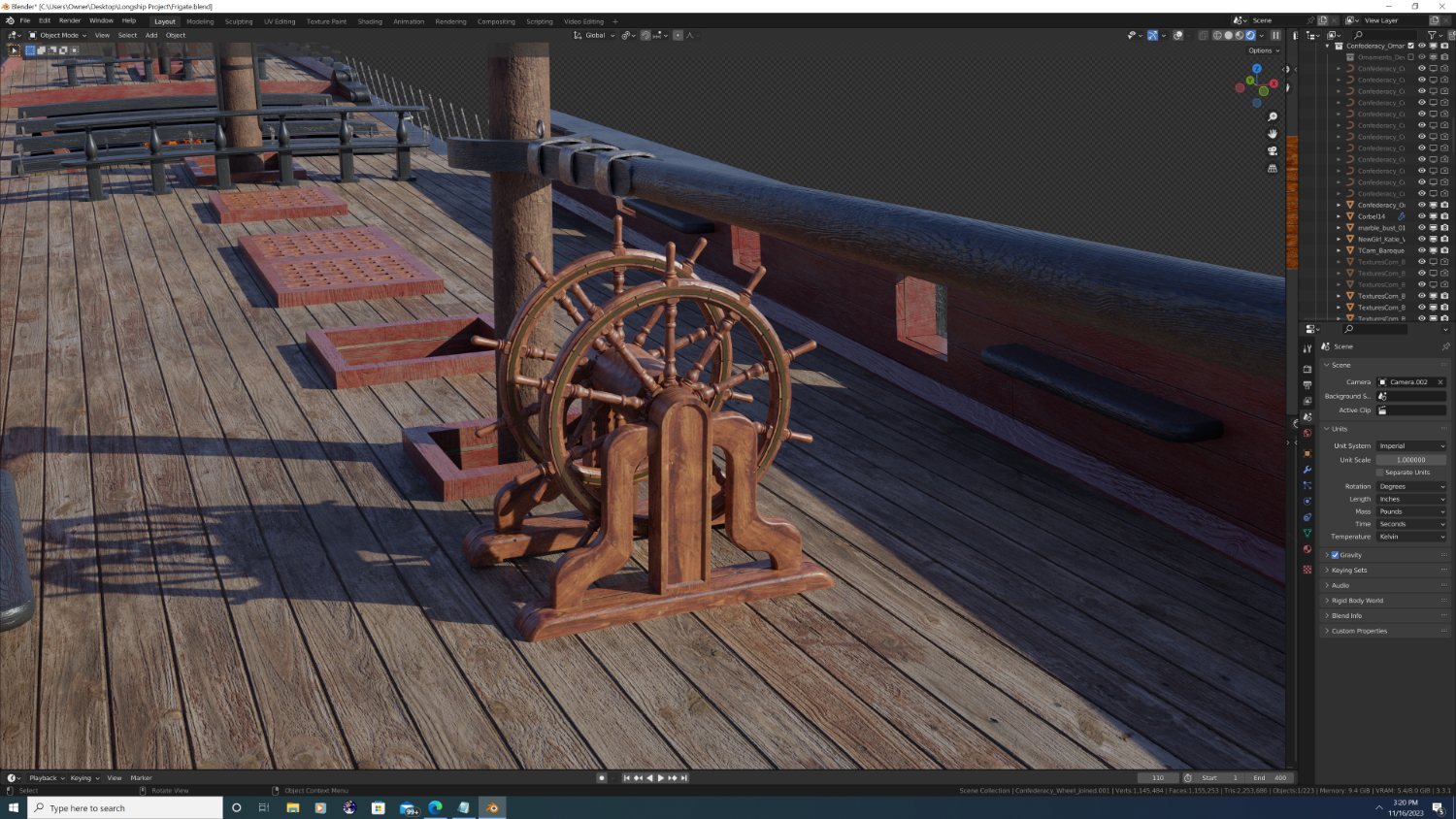
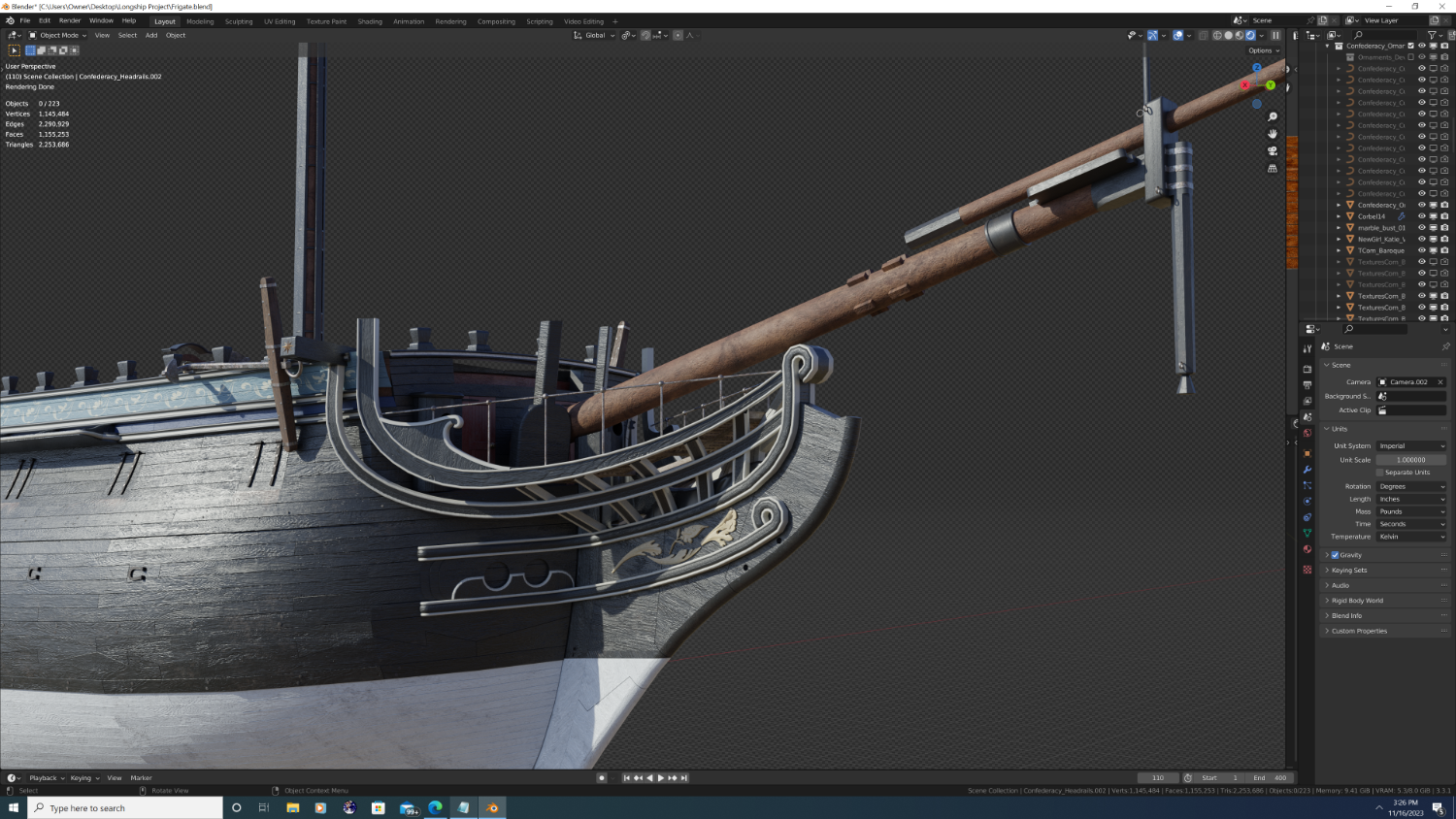
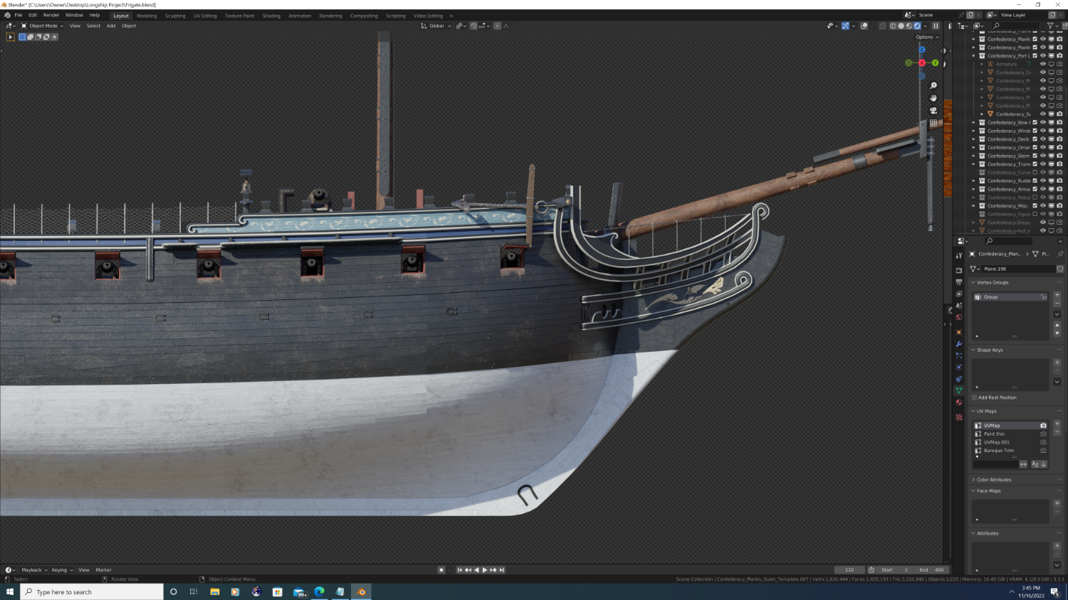
A few updates: 1. Stern Gallery ornamentation updated, added a bit of color, though I tried to use it sparingly to keep an overall 'classic' feel. 2. ship's wheel nearly complete, have to adjust a few angles and heights when I properly place it. 3. Bolsters added / transition of white to black paint corrected (on cutwater) / headrails in the process of being remodeled / beakneck-headrail barracade placed (netting will come later 4. Beakneck Grates started (missing the seats of ease and the angle braces at the tip) 5. Quaterdeck waterways done / Belfry in the process of being redone 6. Midship companionways completed / temporary stove added (Cannons also temporary) 7. Dovetail and horseshoe plates added / Driver boom and gaff imported from Rose (will require adjustments To be continued - smooth sailing t' ye lads (and lasses). -Nate


- 107 replies
-
- 6
-
-
-
- Frigate
- Confederacy
- (and 1 more)
-
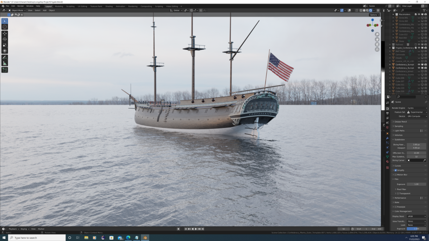
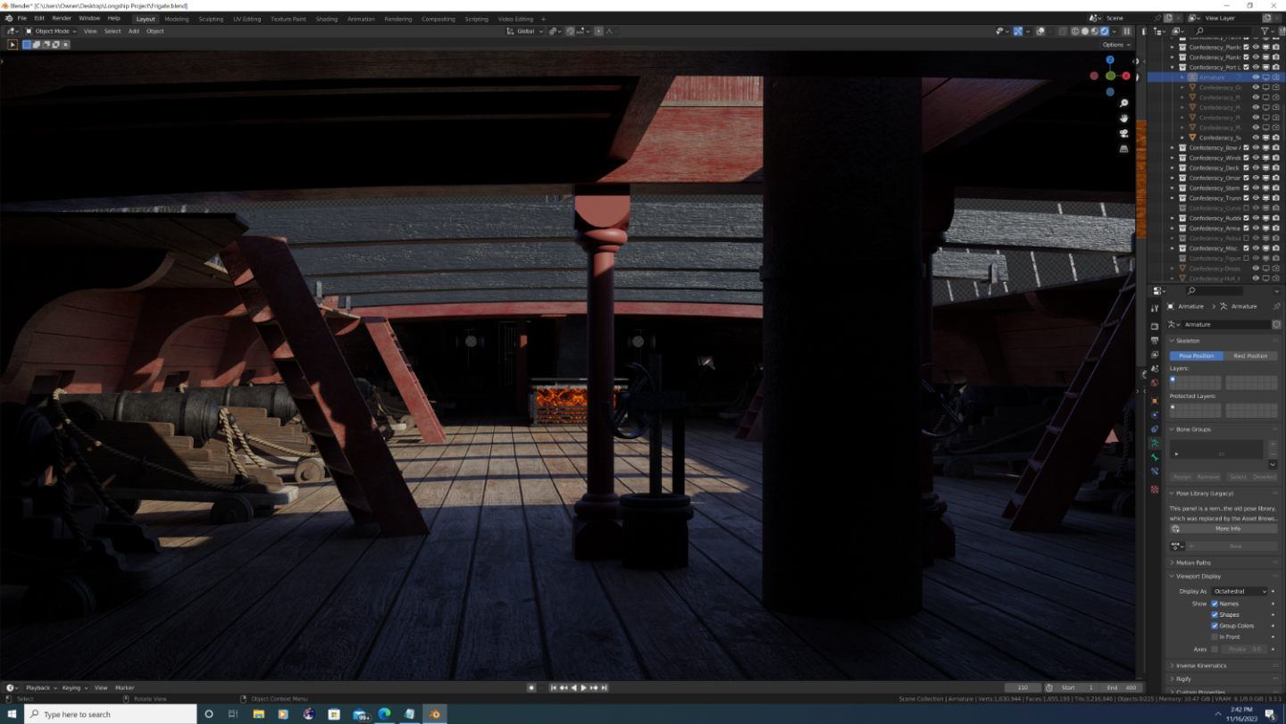
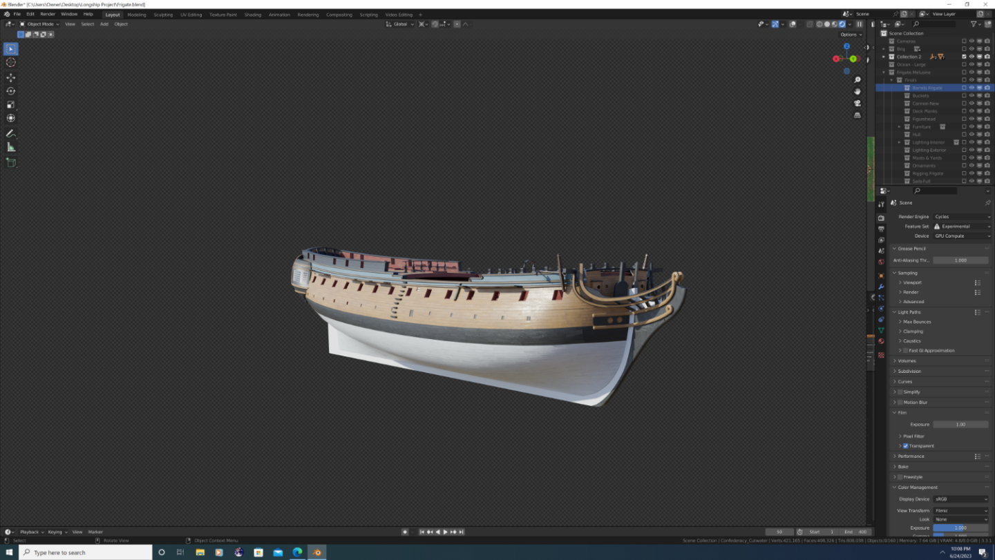
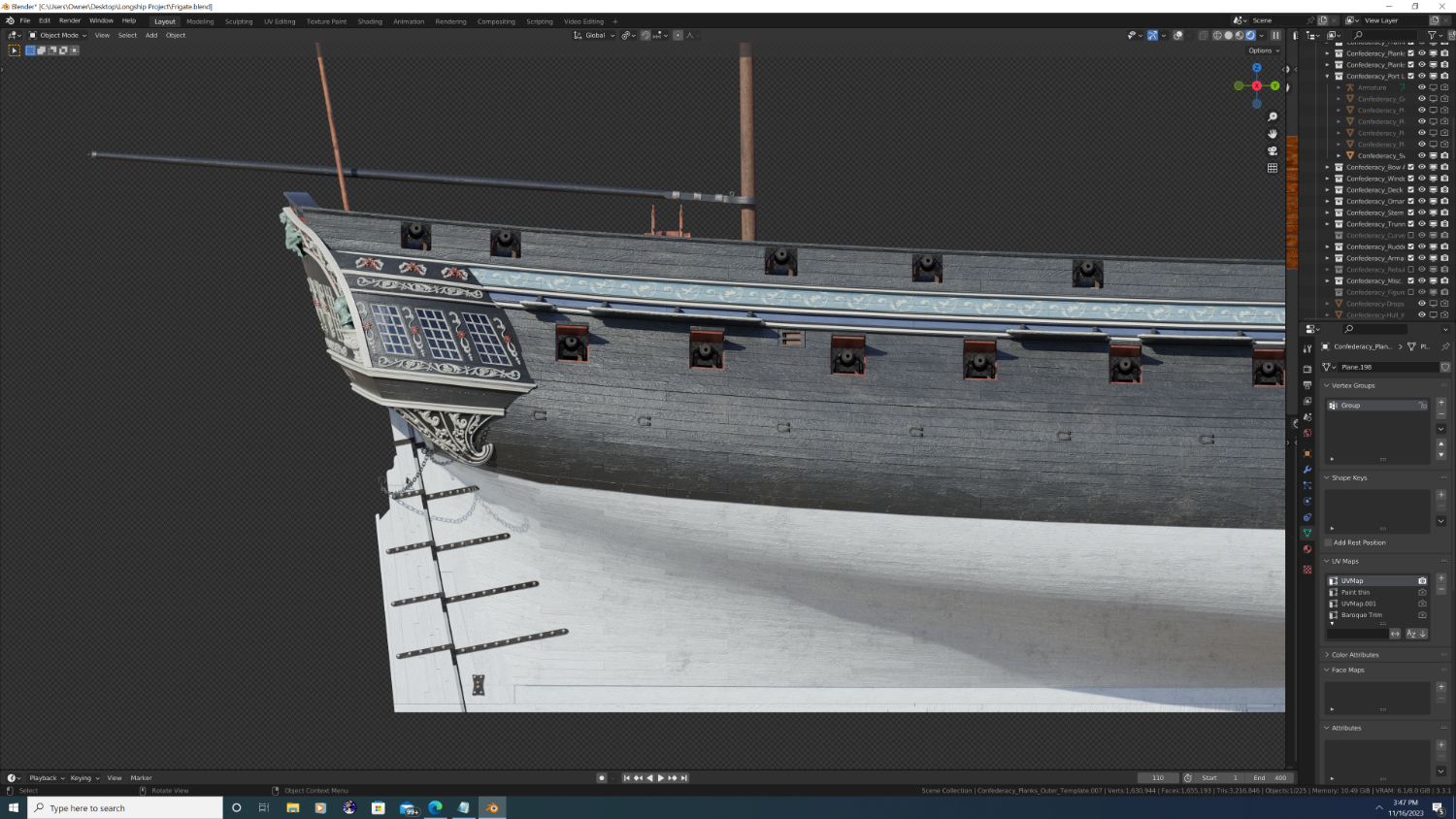
Hi everyone, So after a bit of a hiatus, I'm returning to Confederacy. The Masts, bowspirt, and gaffs are coming along slowly. All the port lids/hatches are in-place (save their rigging. Much of the work at this point has been focused on clean up and redoing key elements that were only 'placeholders'. I'm about a year away from completion of the ship itself, but I'm setting up basic environment components in the scene now. Here's a teaser image:
- 107 replies
-
- 8
-
-
-
- Frigate
- Confederacy
- (and 1 more)
-
Wood, iron, steel... ? Thx in advance, -Nate

-
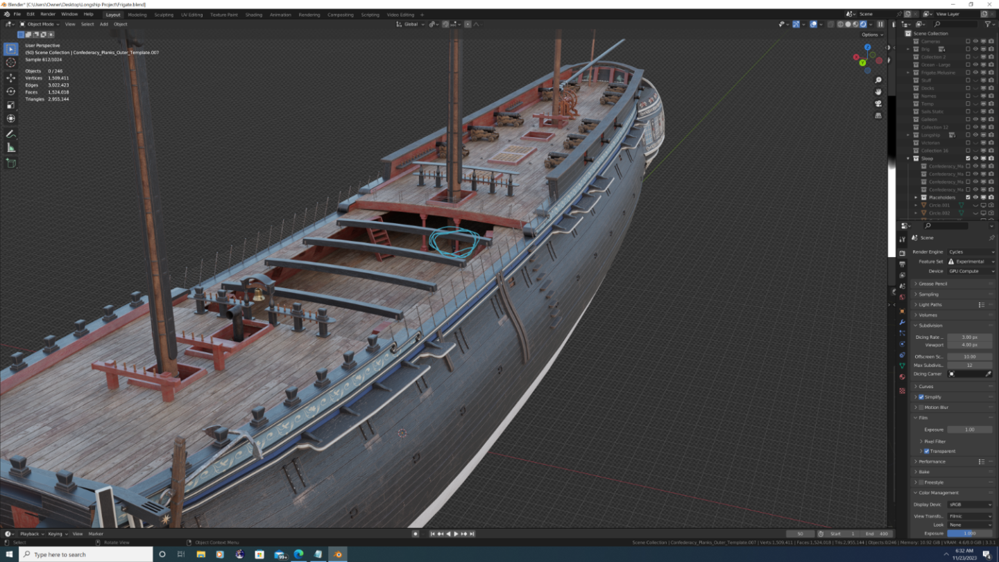
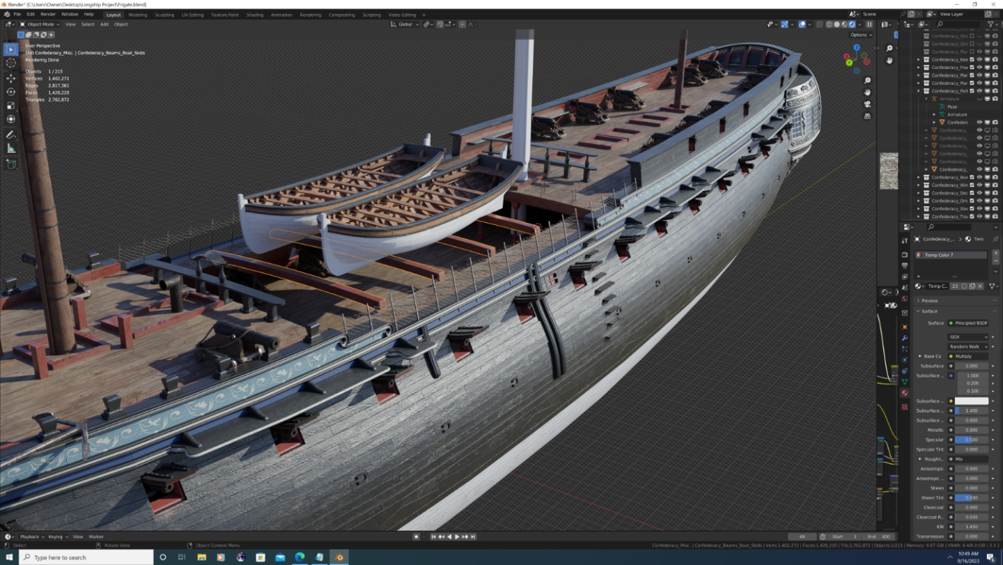
Hey everyone, not sure if this question belongs here or under the general research tab, so forgive me if I'm in the wrong place. Anyway, I was wondering if anyone can tell me the name of the beams that support the boats (highlighted in the screenshot)? I'm guessing these had to be removable to load up the hold when in port, but what prevents them from shifting side-to-side? The holsters (name?) at each end don't appear to have a way to 'clamp down' so to speak... Any info would be appreciated. Thanks! -Nate
-
Thanks And YES!!! Please do get back into it - I was recently looking back at some of your work circa 2013 and gotta say your work (texturing in particular) was well ahead of its time. I'd love to see what you could do with a modern version of blender at your disposal. If interested, I'm also going to be looking for fellow Blender artists to collaborate with in about 6 months to a year from now; perhaps do an epic naval battle scene with several of our ships all together! -Nate
- 107 replies
-
- 4
-
-
-
- Frigate
- Confederacy
- (and 1 more)
-
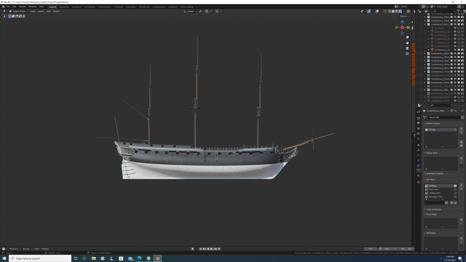
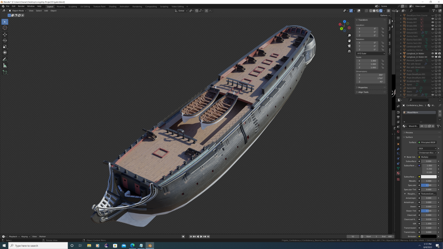
Quick overview shot of current progress in the build.
.thumb.png.efeaeb209c4b0fe01212bbdfff345d45.png)
- 107 replies
-
- 6
-
-
- Frigate
- Confederacy
- (and 1 more)
-
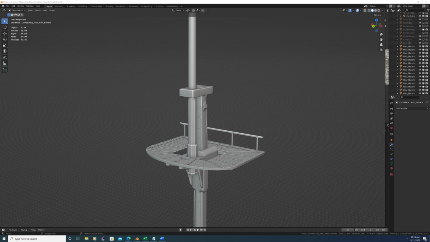
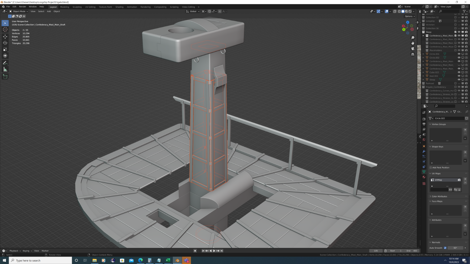
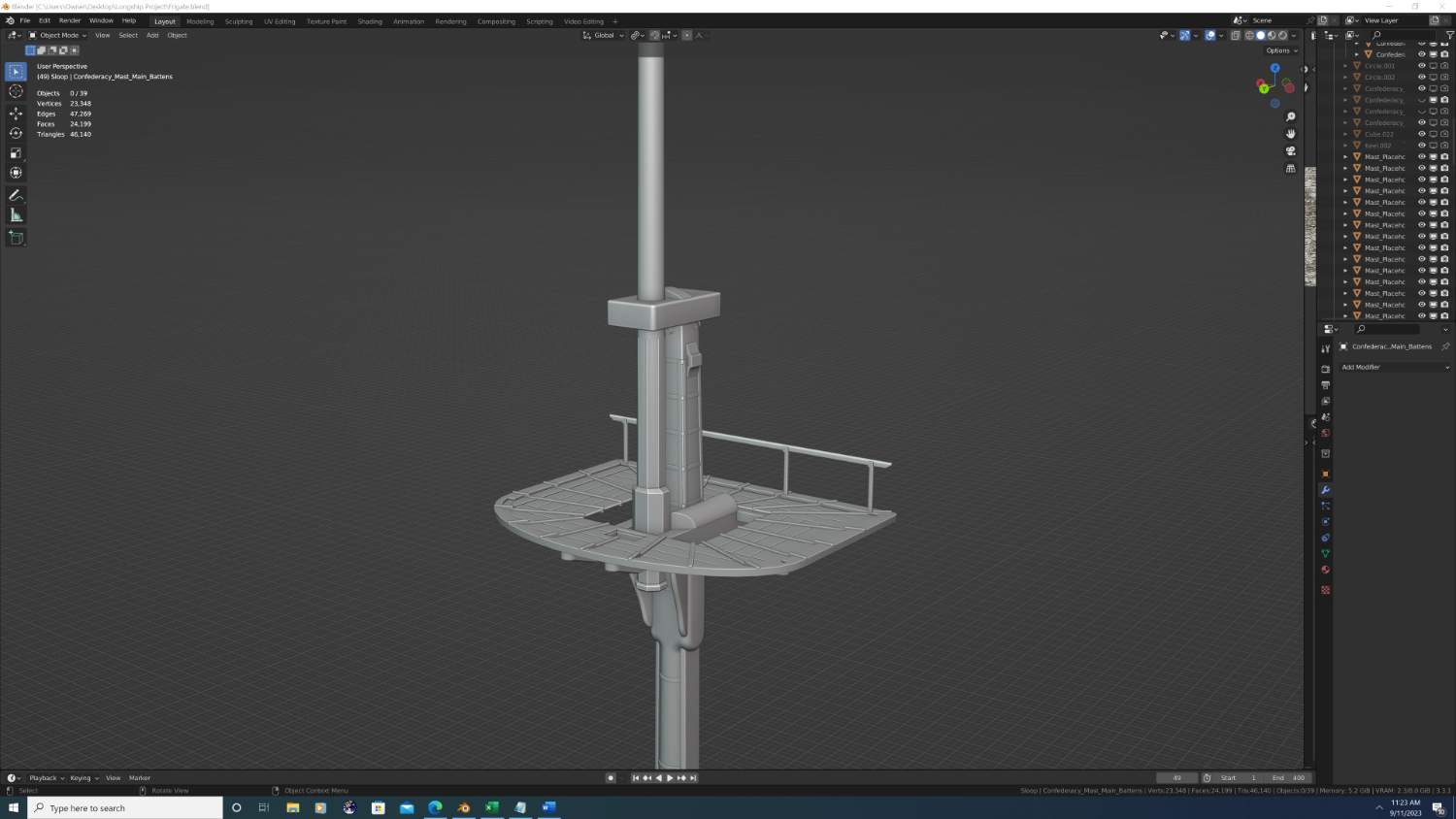
Masting the Confederacy Hey everyone, I’m happy to be back and I’m now working on the masts for Confederacy. I’ve a lot to talk about and solicit feedback on here, so I think it cleanest if I break this post into two parts: · The first part will cover methodology and some underlying decisions I’m making regarding this pivotal part of the build. · The second part will be a detail comparison between the two ships I’ve done and I hope to showcase the improvements I’m making over my 3D Brig Rose, since Rose also used masts taken directly from AOS Pandora (read on for clarification). Part 1: Methodology After extensive research and deliberation, I believe I’ve come up with a good pipeline that will yield realistic results on modelling Confederacy’s masting, yards, and later its rigging. My chosen approach will involve deliberately redoing some things later (a benefit of 3D builds), so in order to not confuse anyone reading this, please allow me to establish a few thoughts and assumptions upfront: 1. AVAILABILITY OF DOCUMENTS: Little (if any) documentation exists on confederacy's masting and rigging. (If you do have or know of any relevant masting plans, I’d be greatly obliged for links/access to them) 2. SCOPE: It is a given that many dependencies exist between the overall setup of the masts, yards, and rigging, but to draw a line in the sand here, let me say upfront that I am only concerned with masting at this point. 3. SOURCE MAT. AND RATIONAL: I want to develop each component from sources that are as complete and comprehensive as possible. Thus, I’ve chosen the AOS Pandora. While I’d arguably be better served were I to begin with plans from more size-comparable frigate, such as the AOS Essex or even online documentation from the Constitution, the precise dimensions of each component has proven very difficult to find. For example: a. Given diameters from step to the partners, then each subsequent qtr. segment diameter. b. Details down to 1/16 of an inch for the tressel trees, cross trees, chocks, hounds, bibs, bolsters… you get the idea 😊 c. The positioning between components, like where the foot/heeling from the topmast segments hang in relation to the tressel trees and caps of the main segments. 4. SOURCE MAT. AND RATIONAL (continued): The AOS pandora does a great job of everything listed in point #3 above. By comparison, the AOS Essex merely provides the maximum diameter and overall length of each segment in a data table in the beginning of the book, then only a scale drawing - with no dimensions - later on in the actual masts and spars section. 5. ADAPTATION: Having said that, do plan on adapting Pandora’s masts and spars to Confederacy in the following ways: a. ORIGIN AND RAKE: The origin of the steps and approximate rake of the masts is depicted on Confederacy’s framing and deck plans. To make some of the math easier I’m rounding to the nearest ¼ of a degree. b. PROPORTIONAL SCALING: The factor that most contributes to ‘realism’ is the overall proportions. Thus, if I can later establish any actual dimensions of Confederacy’s masts/spars, I should be able to extrapolate precise dimensions based on the proportions given to me by Pandora’s documentation… within reason, of course. (I won’t be making Confederacy’s masts 100 ft taller than Pandora’s just because it is 33% longer ship, lol) c. HARDWARE ADAPTATION: Finally, I will add, subtract, or swap out various hardware based upon belaying points and other differences in rigging configurations. Examples include: # of hoops and wooldings based upon total extrapolated length, angle (spread) of the bibs after the platform is tilted forward to compensate for the true rake of each mast, # number of thimbles to support the correct number of bowline blocks require for the adjusted sail sizing. Would a turn of the century ship still have used crows’ feet? Would the adjusted platform size require an extended mast cap and an additional support column… again, you get the idea. Smooth sailing, -Nate
- 107 replies
-
- 3
-
-
- Frigate
- Confederacy
- (and 1 more)
-
Haha yeah, no worries... And to clarify something I said earlier, I'm currently using two textures: a bronze patina and a copper patina. Yes, I highl doubt that they were using pure bronze sculptures (not just cost, but also weight would become an issue). Now what we call bronze is an alloy, which I'm sure you know . The two most common alloys of the time were bronze and steel (original steel, not modern HCS). Steel has under-pinnings of iron; bronze has a copper foundation. That said, bronze is usually mixed with zinc, lead, or tin, all of which were beyond abundant in the Appalachians. And, as you alluded to earlier, a by product of this naturally occurring metallurgy is arsenic - highly toxic indeed! Anyway, while all that science/history is really cool - the actual modelling decisions I need to make are: Can I justify the pale green/ turquoise look of the sculptures? Can I justify the patinaed look on the sculptures? If not, what are my options? (remember this was an American ship, built at a time when we were definitely trying to distance ourselves from our English cousins...) Interested to know your thoughts. Thx as always, -Nate
- 107 replies
-
- 1
-
-
- Frigate
- Confederacy
- (and 1 more)
-
Interesting... I'm curious, when Hunt writes "... (nothing)" does he mean he had no information to give Weir, or that there was no figurehead on the original HMS Surprise (HMS ROSE)? It could be interpreted either way. Aside - I'm going to stop referencing HMS Rose, and assume its well established that anytime we reference the Surprise, we mean the Canadian reconstruction of Rose, purchased by WB and renamed Surprise for the film.
- 107 replies
-
- 1
-
-
- Frigate
- Confederacy
- (and 1 more)
-
Good to know Mark, thanks! I was also wondering about use of paint to simulate bronze patina? A notable example of this would be the HMS Surprise (HMS Rose)... The figurehead here is really what I'm shooting for, and there's a scene in Master and Commander where the crew is patching it up... in that scene, the underlying substance is clearly wood, so I'm wondering how they achieve the metallic look, complete with oxidation streaks... I would be curious to know your thoughts? Thanks!
- 107 replies
-
- 2
-
-
- Frigate
- Confederacy
- (and 1 more)
-
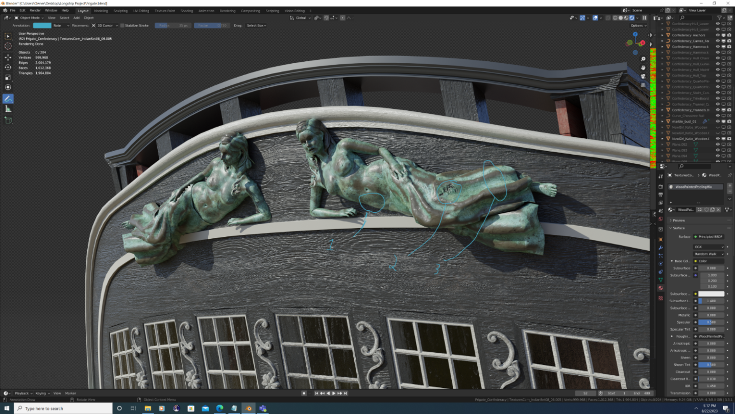
@Martes - Hard to see from one screenshot, but if you were to look really close at the texture, I even went so far as to try to mimic a thin layer of bronze/copper atop a wood carving. I do believe the gilding - likely bronze due to copper shortages in the Americas during the revolution - to be historically accurate. The 'patina' material refers to the oxidation of these metals and occurs faster on thin layers. To accomplish this in 3d, I mixed the normal maps of the wood grain smoothly with that of the bronze sculpture material at about a 30-70 percent ratio. I then sharply painted the corrosion (patina) to the cervices (I tried using geometry nodes to calculate where the actual cervices are procedurally, but that proved to be serious overkill). The albedo/diffuse maps only mix the bronze and patina materials, understandably. As to the question of budget, yes there were funding issues during Confederacy's construction - lots of them! Yet Confederacy was built to impress; to be the unofficial 'flagship' of the American Navy at the time, and ironically, historical letters of correspondence will show that money was in fact wasted on her external beauty while neglecting important things like copper sheathing or even, you know, cannons. SCREENSHOT REFERENCE KEY: 1. Wood grain normal/bump map visible 2. Bronze normal/bump map visible (Note the chipping and denting effects) 3. Hand-painted patina effect. As an added bit of realism, the patina mapping also controls the metallic shader (Bronze is a ferrous metal, whereas rust and other environmental corrosions diminish these light-based properties)
- 107 replies
-
- 3
-
-
-
- Frigate
- Confederacy
- (and 1 more)
-
Quick update: Starting to add ornamentation to the stern gallery, quarter galleries, and deck houses Color theme changed to a more 'classic' black and white theme, with patinaed (both copper and bronze) sculptures Rudder end cap completed Bolts finished on the gudgeon and pintle straps + much more not shown in this particular screenshot... addl updates to follow soon!
.png.58216ef9e1f0210c6c6a1437e3e0f9ba.png)
- 107 replies
-
- 4
-
-
-
- Frigate
- Confederacy
- (and 1 more)
-
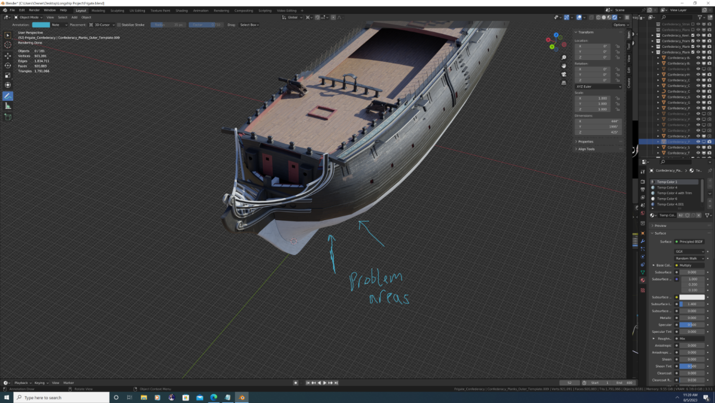
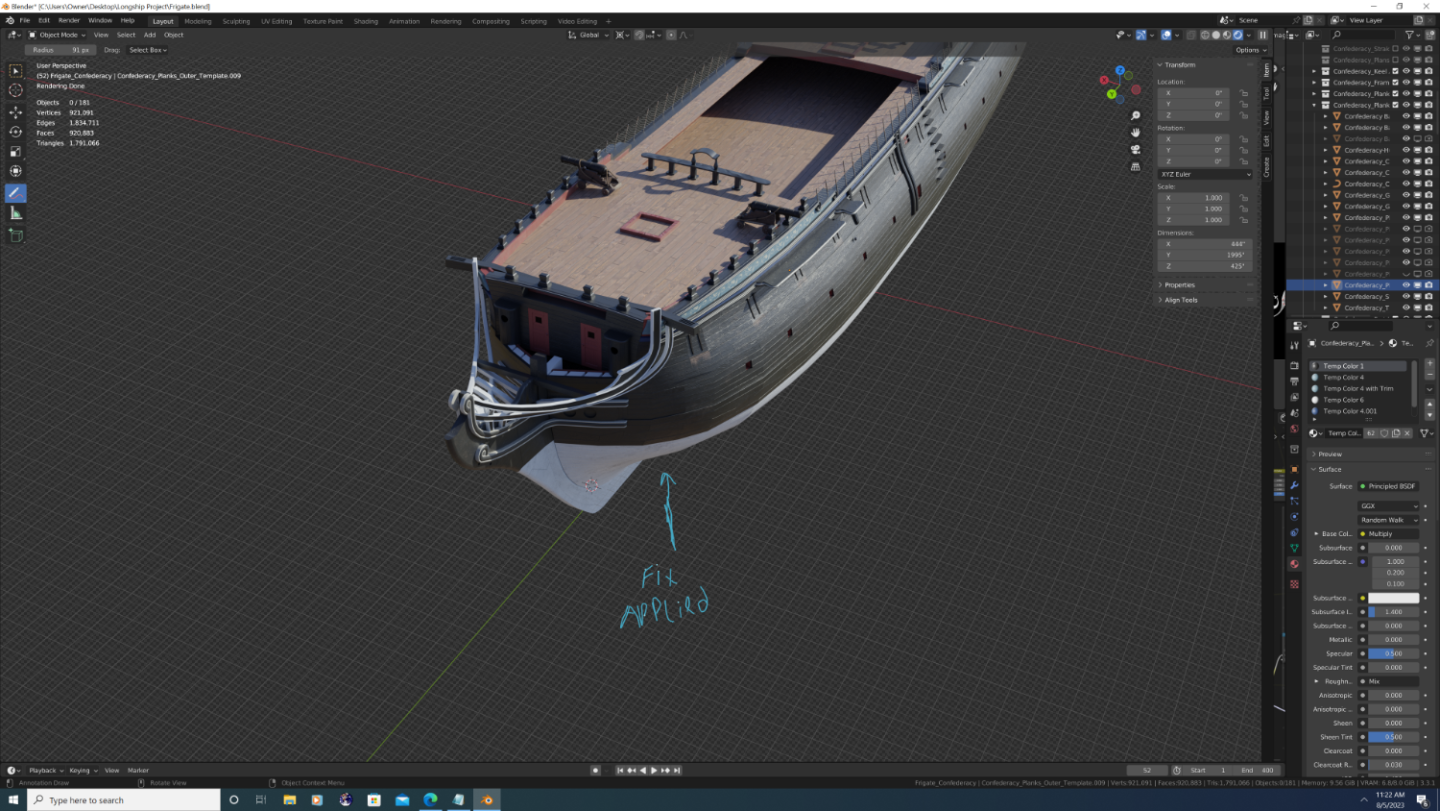
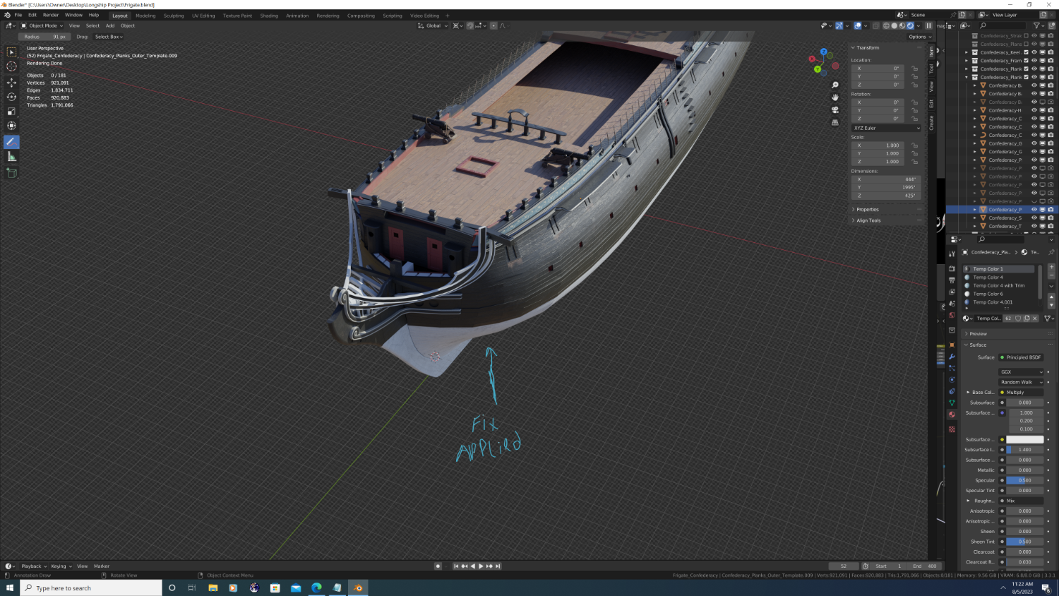
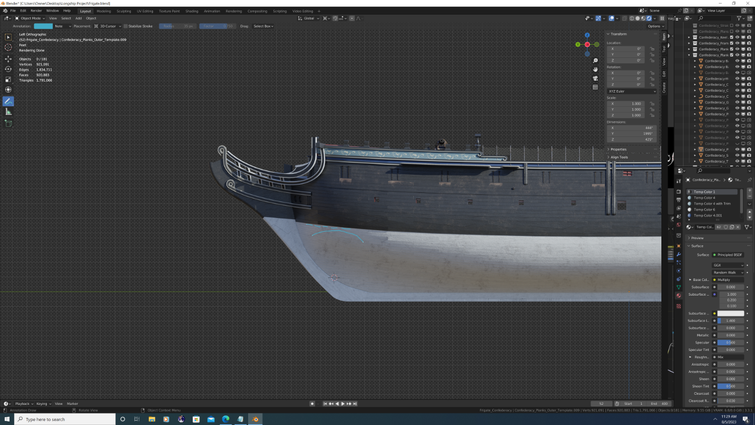
@Martes - moving our conversation to the build log as others may benefit from your advice as well. Okay, so I've done a quick and dirty fix to the 1st problem area you pointed out. A couple things: I do think for this to work, I will have to do the section immediately aft as well. also, I did my best to move the camera angle so the sun illuminates the top of each strake so we can see what's happening from top to bottom as you look down the hull (not sure it'll come out in the compressed photos though). Here's the before and after shots... 1. Before 2. After I am getting a slight 'warp' in the wale because, technically speaking, the additional smoothing would have to be perpendicular to the normals (i.e. normal tangent) and not just global XYZ to be correct. Still, it's encouraging that this may be easier to do than I initially thought. Thx, -Nate

- 107 replies
-
- 4
-
-
- Frigate
- Confederacy
- (and 1 more)
-
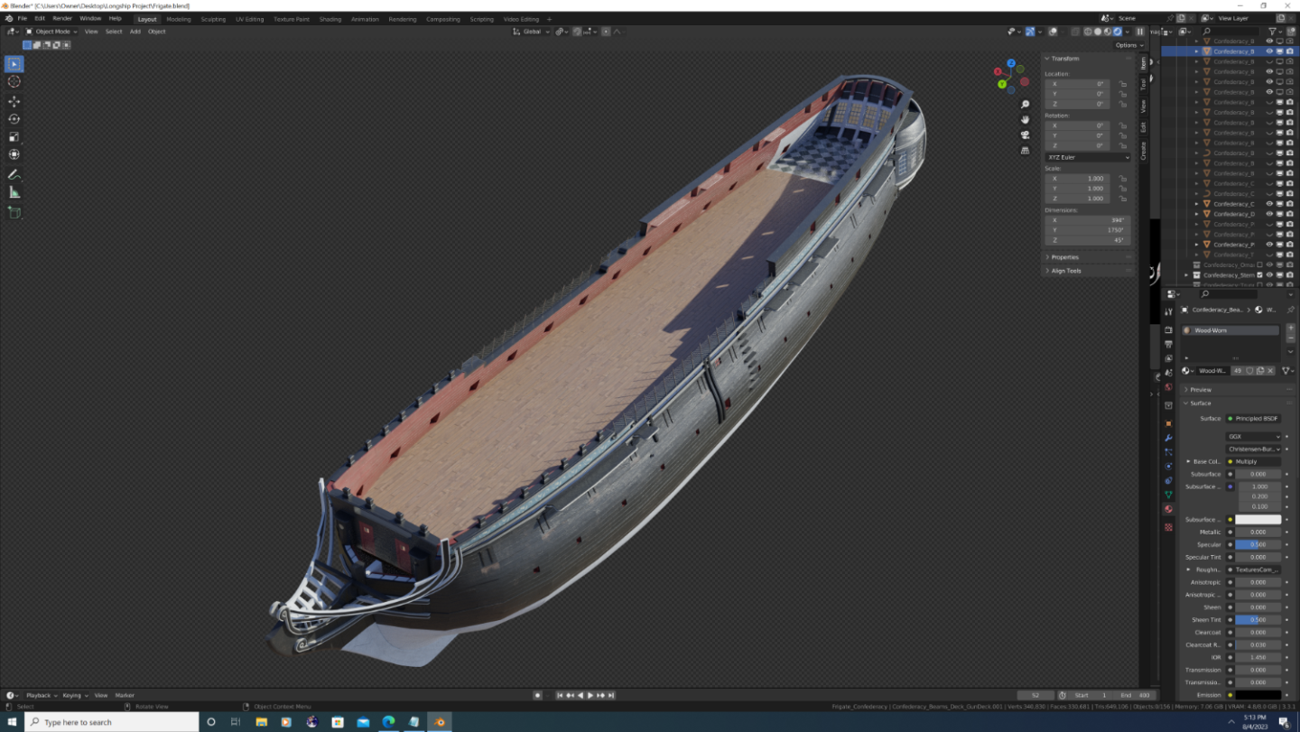
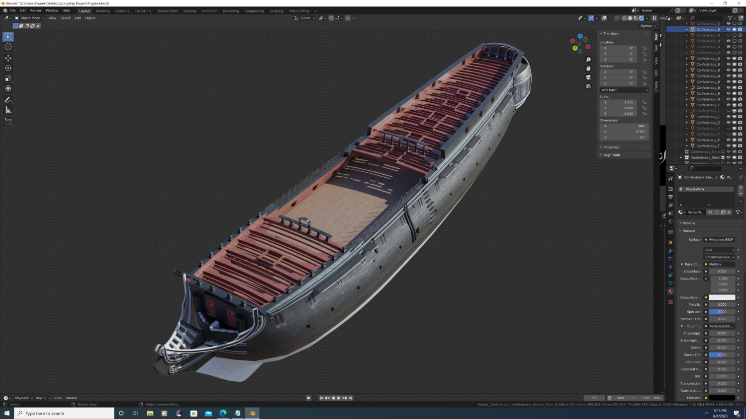
Under the hood shot of the deck beam and framing. As it seems to be working well for this project, I once again modelled general shapes first, then gradually upped the detail and sophistication in subsequent passes and/or working sessions. About 50% done with the deck framing, at which point I'll move on to partitions, hanging knees (knee braces), and then the 'fixed' fittings.


- 107 replies
-
- 5
-
-
- Frigate
- Confederacy
- (and 1 more)
-
This is the first of about a dozen relief sculptures that outline Confederacy's stern. I will use two organic characters I modelled from scratch for a 3D anatomy class I'm taking online - one male, one female - to get all the sculptures added to the stern. I will then use their armatures to not only pose them properly, but to change their facial features and body types subtly, so that hopefully in the final product they will look as if each one was carved individually, and so they don't look like clones of one another (even if in fact they are). Her hair is a different story. This will be the only time in this project that I use 3rd party models. I've decided to spend the $5-$10 bucks and buy a real-time hair pack from an online marketplace. Note: This one was very hastily posed, at this point I'm simply getting a feel for approx size as well as experimenting with how to get the cloth simulation to drape her skirt in a way that it looks like wood. Ironic, isn't it... cloth made to look like would that was sculpted to look like cloth? Anyway, here she is...
.png.86db05ade088cb29b429cbe1aedc98e6.png)
- 107 replies
-
- 6
-
-
- Frigate
- Confederacy
- (and 1 more)
-
@Bruma - Thanks! Yeah, for a 'labor of love', this project certainly feels a lot more like a labor at times. And I'm always excited to meet fellow blender users
- 107 replies
-
- 1
-
-
- Frigate
- Confederacy
- (and 1 more)
-
And we have a winner! Bear in mind this is a preview of the color theme only... The actual texturing will take months and will look much, much better To give you all an idea - I haven't even UV unwrapped everything yet. I just wanted a break from modelling. Still, not in bad shape for the 3 month mark.
.png.48b8d0a16335b56c68312dcd0760cb5d.png)
- 107 replies
-
- 8
-
-
- Frigate
- Confederacy
- (and 1 more)
-
Option B: A slightly more muted color scheme, visually similar to to that of the Continental Army's officer's uniform.
- 107 replies
-
- 4
-
-
-
- Frigate
- Confederacy
- (and 1 more)
-
A preliminary color concept for confederacy.... A bit 'out there' but it conforms to all historical correspondence as to her appearance.
- 107 replies
-
- 4
-
-
- Frigate
- Confederacy
- (and 1 more)


.png.533f4c49d231c312249effa83d607361.png)


.png.9339b0a0f9b46e145b96ec08325fb33d.png)
.png.dc70f97b18580159f4e09ec6ec0adcc0.png)