3DShipWright
-
Posts
197 -
Joined
-
Last visited
Content Type
Profiles
Forums
Gallery
Events
Everything posted by 3DShipWright
-
Redoing Oseberg
3DShipWright replied to KrisWood's topic in CAD and 3D Modelling/Drafting Plans with Software
Yes, Blender supports the .svg format if that works. Regarding the published plans question, a few thoughts: 1. I think the reason the pdf documents are gated in this case is so that they can run analytics on who is using their research and for what purposes. 2. I would also argue that research by itself, is not intellectual property. I am in no way diminishing the scholars' effort, but the work was derivative; it can't be patented. And if there's anything I know about academics, it's that if they could monetize their work, they would've. To draw a parallel to the NMM in Greenwich, the RMG does sell copies of admiralty plans because they hold accurate, original copies of the plans and the ships themselves (other than those they stole) were property of the English government. Even so, the licensing is unrestricted aside from commercial use, and their site says simply to credit them and contact them and they may "support education and scholarship and encourage research in our collections by waiving licensing fees for certain uses." 3. Finally and most importantly - To even be considered a 'reproduction' the copy must be the same media or type as the original. To my knowledge, nothing published on the Oseberg site has been digital cad files for the purpose of 3D printing, nor making templates from which to construct a model ship. Think about it this way, they transcribed a physical object into print media, now you are transcribing print media into digital media. If anyone is owed royalties here has been dead for over a thousand years. So yes, I would recommend crediting your source material wherever possible. I also think it may be courteous to thank them via an email, a good review, or a small donation (whichever you feel appropriate). But I don't think sharing a free document for purposes of a non-commercial project should even be a factor here. -
Redoing Oseberg
3DShipWright replied to KrisWood's topic in CAD and 3D Modelling/Drafting Plans with Software
Hey Kris, Cool stuff! I'd be happy to do some collaboration with you. I love longships and have even been tinkering with doing one of my own over the last couple of weeks. Let me know if I can be of any assistance. -Nate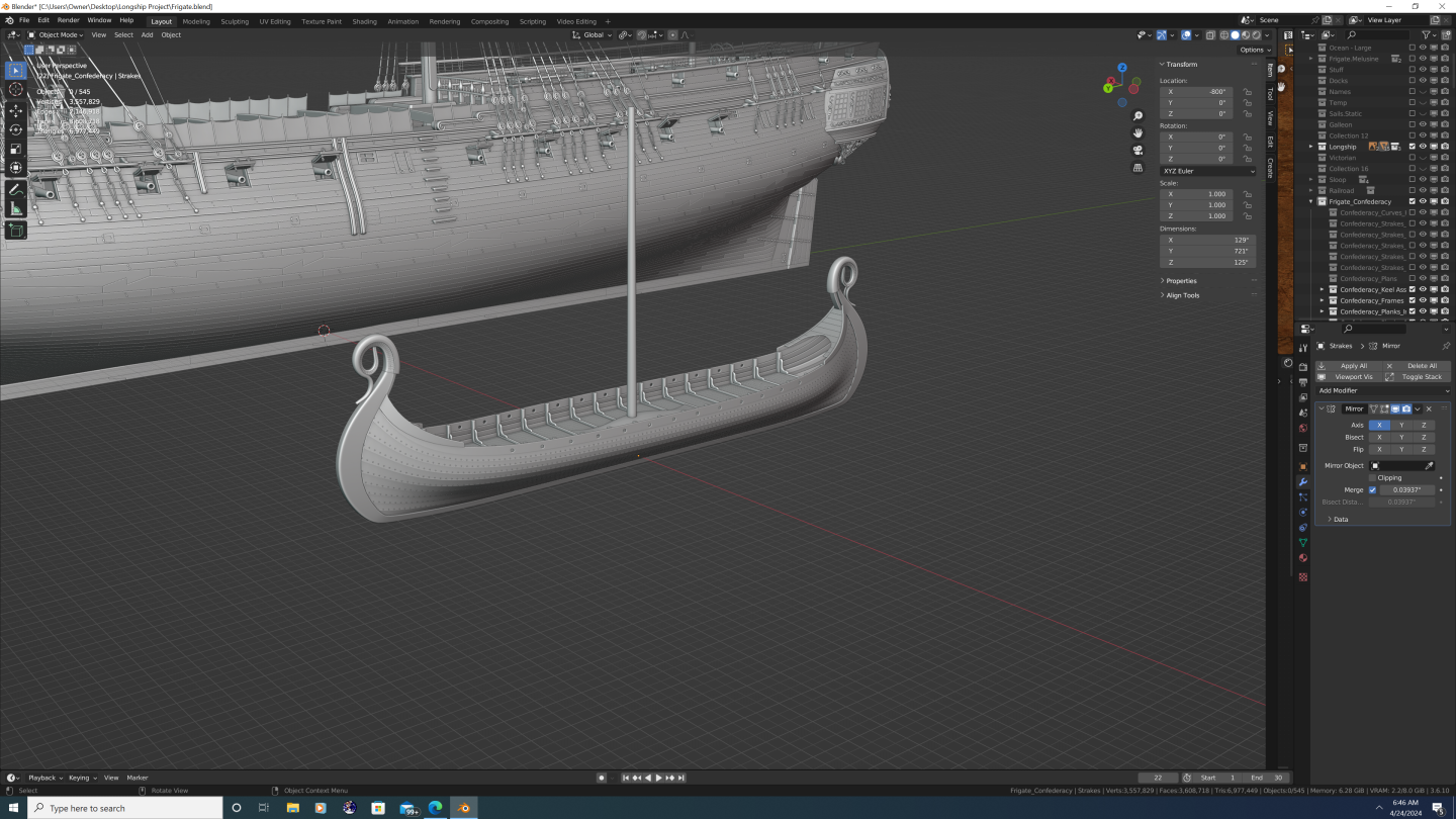

-
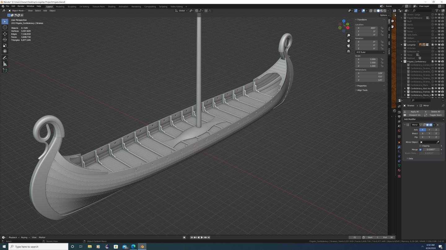
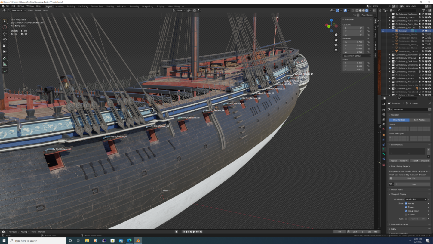
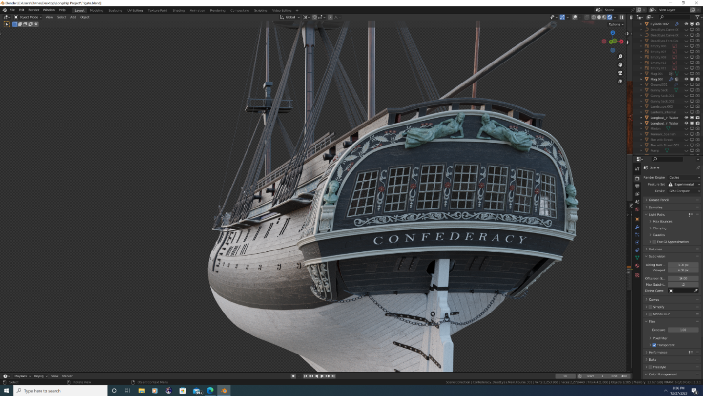
Hi Everyone, So after a bit of a hiatus, I'm back with the first of three major update posts to Confederacy. In this post, I'll cover updates to the bow and a couple of minor enhancements to the outer hull. Change log is first, photos at the end. As always, feedback most welcome! Upper headrail remodeled to taper properly. Pendant joint added at the top. Carling atop the upper headrail remodeled; trim rail now blends smoothly where it meets the rail Lower headrail remodeled as two distinct pieces that follow the hull and connect with the bottom of the catheads Upper and lower headrails are now adorned with decorative reliefs Hanging knees installed beneath the catheads Boomkin holsters installed the upper headrails to support the bumpkins Beakhead platform flattened, height adjusted; position of the doorsand round houses adjusted accordingly Ledges that connect the beakhead platform to the prow grating installed Seats of ease installed in front of the bumpkins atop the grating Color theme of the bulkhead has been updated; doors and roundhouses are now white; decorative motif (white on blue) carried over from the side of the hull Gammoning slots cut into the gammoning knee have been corrected so they aren't covered by the headtimbers Safety netting added to the headrail barricade Tip of the cutwater has been cut back a bit to accommodate the figurehead Horseshoe plates flipped from heel to toe (I had them on backwards originally) Bower anchors haver been upscaled to their (nearly) correct size Chain plates, channel ties, and straps (lanyards) in place on the forward channels; main and mizzen channels in progress Inboard and outboard rings installed on all gunport lids; outboard rings each have their own bones in the armature allowing them to pivot as the rope pulls the port open And now the photos:
.png.e30a775e7328b0f5425ba4df7de239d4.png)
.png.9fa02f561a3c1b3c45d613aed39cddc9.png)
.png.67b61ceadb93bb46dbce27dec20f46fb.png)
.png.0267900e1530d92a7ef350d996c78713.png)
.png.32f543725c5afaa1e6144beded8d2d7e.png)
- 105 replies
-
- 3
-

-

-
- Frigate
- Confederacy
- (and 1 more)
-
@64Pacific - Thank you so much for the kind words. While I won't undersell the amount of time or tediousness of such an undertaking, I absolutely love following the projects of the other 3D artists on this forum and draw continued inspiration from their works. Specific shout outs to @CDR_Ret and @Martes for their continuous updates (both blender users) that keep me engaged in my own projects, even if I'm not as disciplined at sharing regularily. And many other talented artists I many have missed. Finally, from an aspirational perspective, I'm still very humbled at what @herask was able to do on his swan-class (HMS Pegasus) 3D model. It is one of the most comprehensive digital ship models I've ever seen, even among the professional 3D artist's portfolios over at ArtStation. In point of fact, it's that level of detail that I hope Confederacy has when finished. Point is, give it a go! There's a great community here to cheer you on and provide assistance should you need it. Best, -Nate
- 105 replies
-
- 4
-
-
- Frigate
- Confederacy
- (and 1 more)
-
3D Ropes/Rigging in Blender
3DShipWright replied to 3DShipWright's topic in CAD and 3D Modelling/Drafting Plans with Software
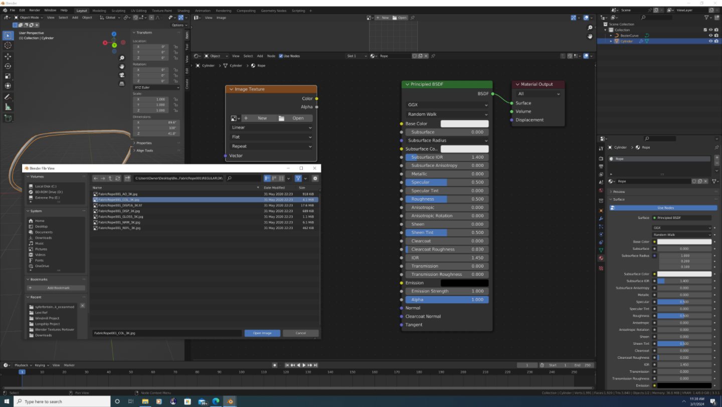
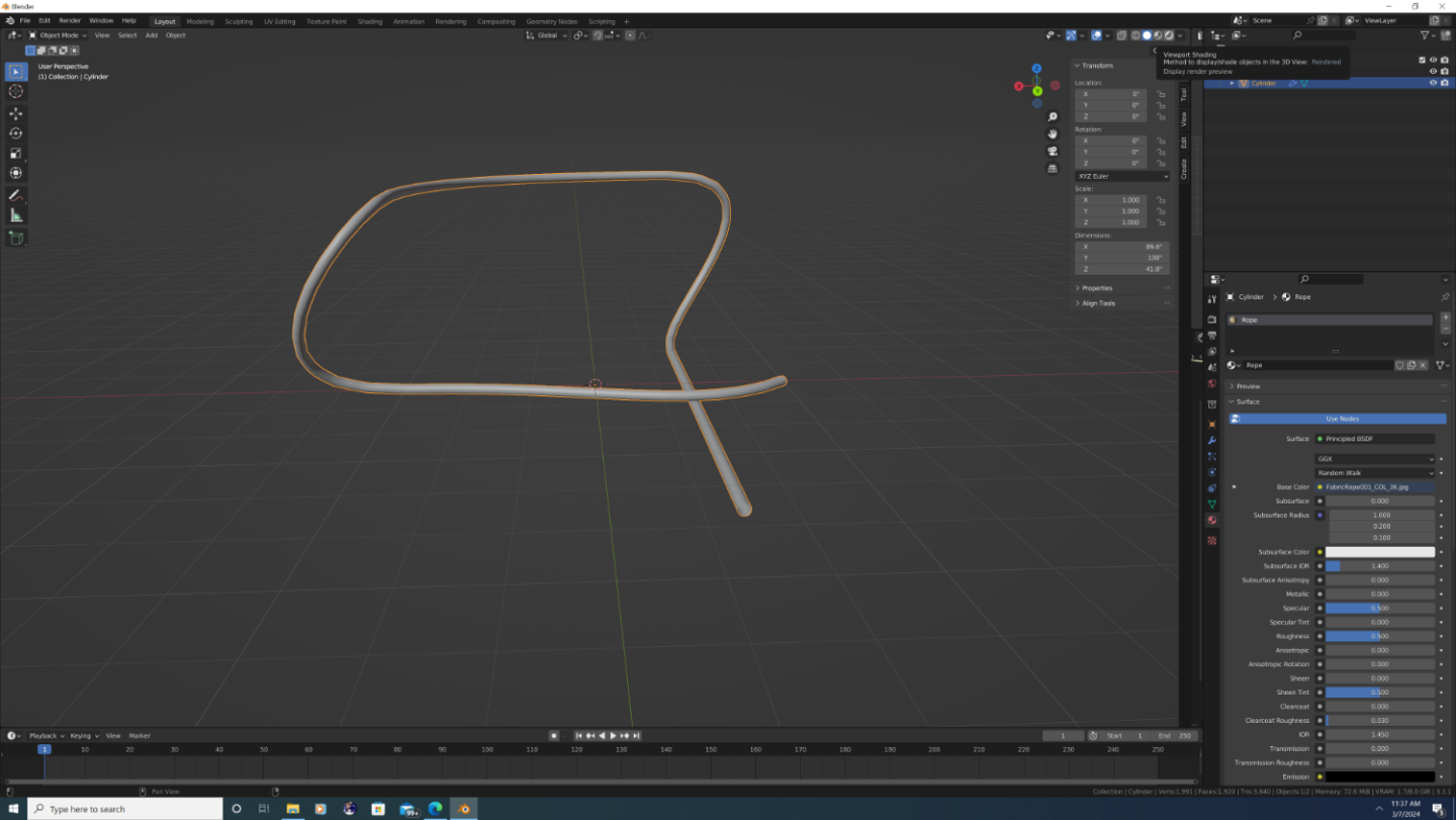
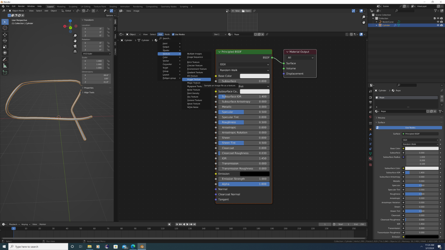
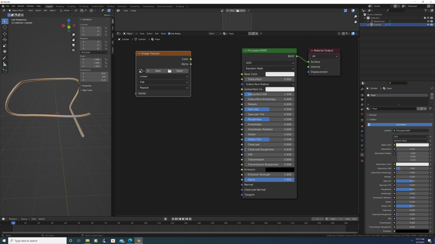
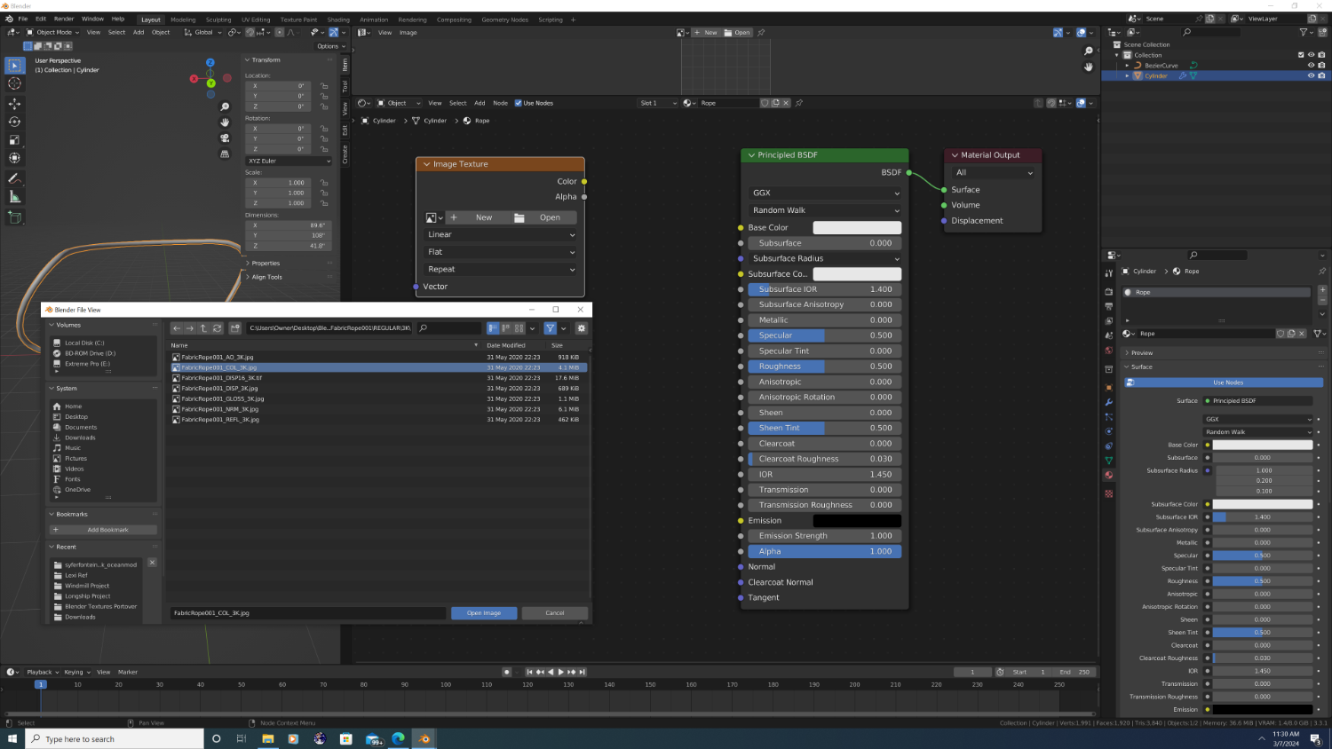
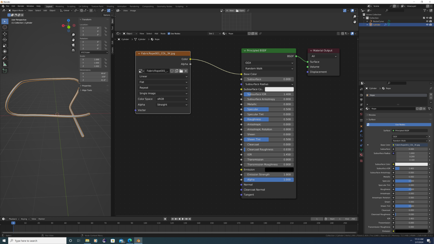
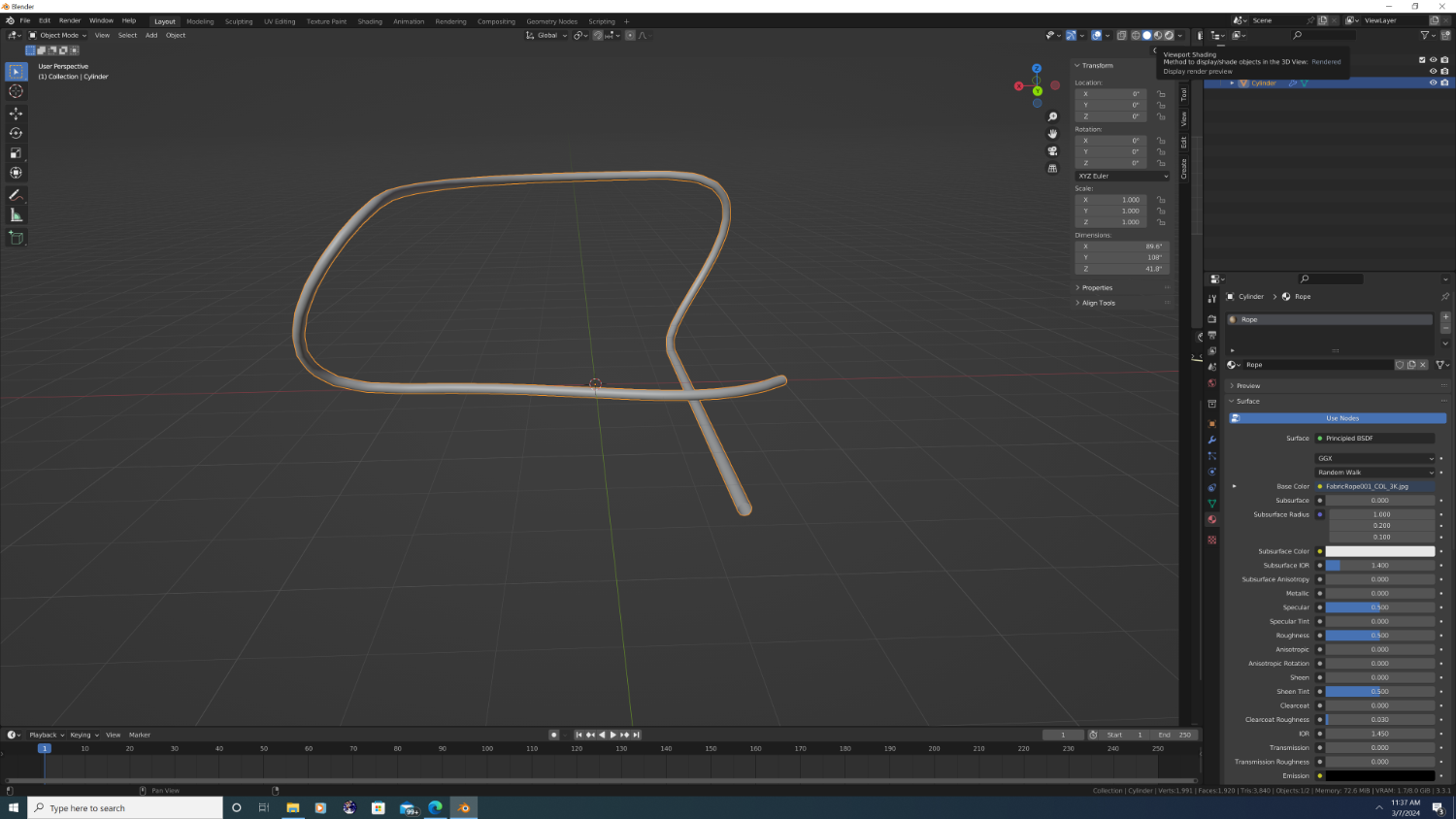
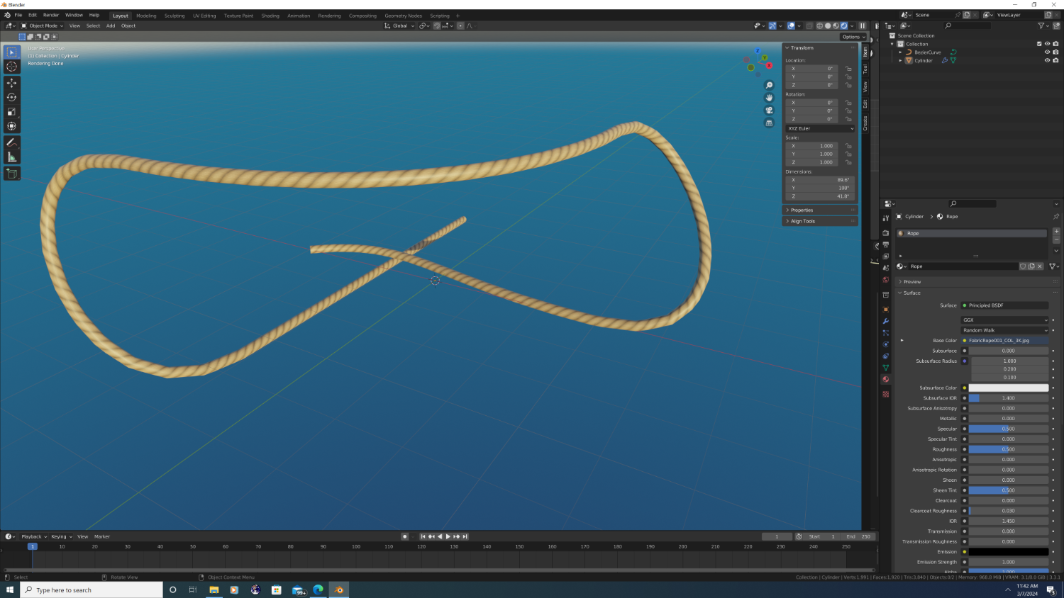
Okay, so I've expanded the Shader Editor and have zoomed in to see the two boxes. The title of the two are "Principled BSDF" and "Material Output" The 'Material Output', as the name suggests, is the master output of our node. This is our always-on node, and 99% of the time, only the green 'surface' bus is used. For purposes of this tutorial, we can ignore the output box entirely. (note to advanced users I will be sticking to bump map workflows and will not be covering vector displacement, nor volumetrics, blackbodies, etc.) So in the olden days, Blender had different shaders - with their own settings - that you'd use to create materials. At the time, you would use a different shader, or combination of shaders, to create something like glass or water than you would use to create a wood, fabric, or plastic material. Thankfully, a few years back, blender introduced the principled BSDF shader, which can be used for almost everything - from organic materials like skin, all the way to complex metals, and everything in between. So lets take a look at it... Obviously, there's alot here, but we really only need to connect something to the 'base color' input to create a simple texture. So lets do that. If you haen't already download your rope texture files and find the one that was meant to be the base color. This is super easy, as it will be the only image in the set that is in color, looks like a picture of rope, and is not bright purple (Normal map). Go to Add->Texture->Image Texture and a new bx will appear. And after... In the new image texture box, click on 'open' and blender with open a directory where you can browse to where you have your texture files stored. Once it loads, click and drag to draw a line that connects the 'color' output of your image texture node to the 'base color' of the Principled BSDF shader. We'll add the other images in a moment but I want to point out that even now, our rope is textured. To illustrate, I'm going to make the3D Viewport bigger, and change the Viewport Shading method to rendered (the top-right most circle icon in the viewport), as seen here. and after... So there's our rope - and with a texture... Just not very convincing at this point. Not to worry ***Continued in next post***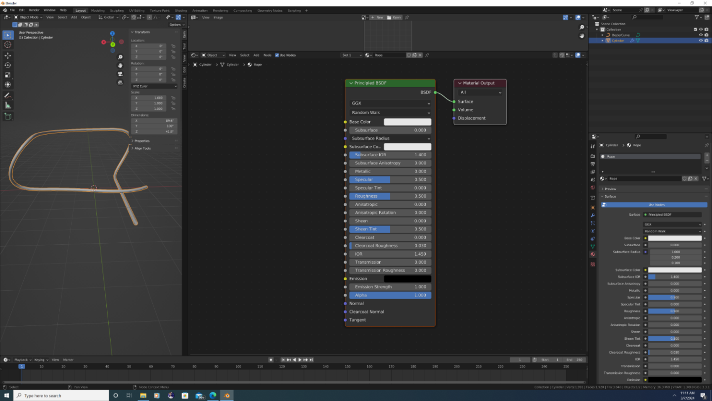


-
3D Ropes/Rigging in Blender
3DShipWright replied to 3DShipWright's topic in CAD and 3D Modelling/Drafting Plans with Software
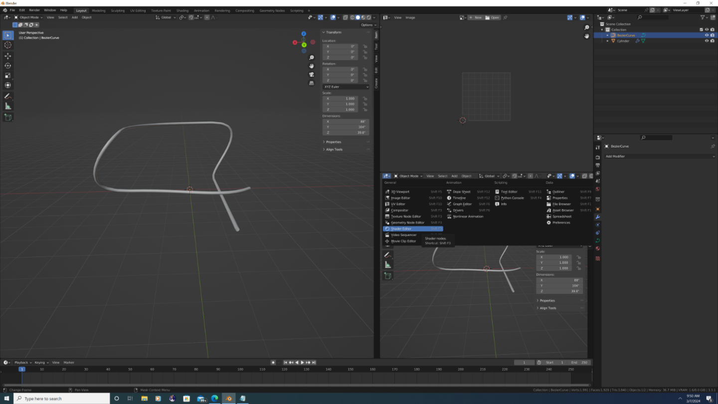
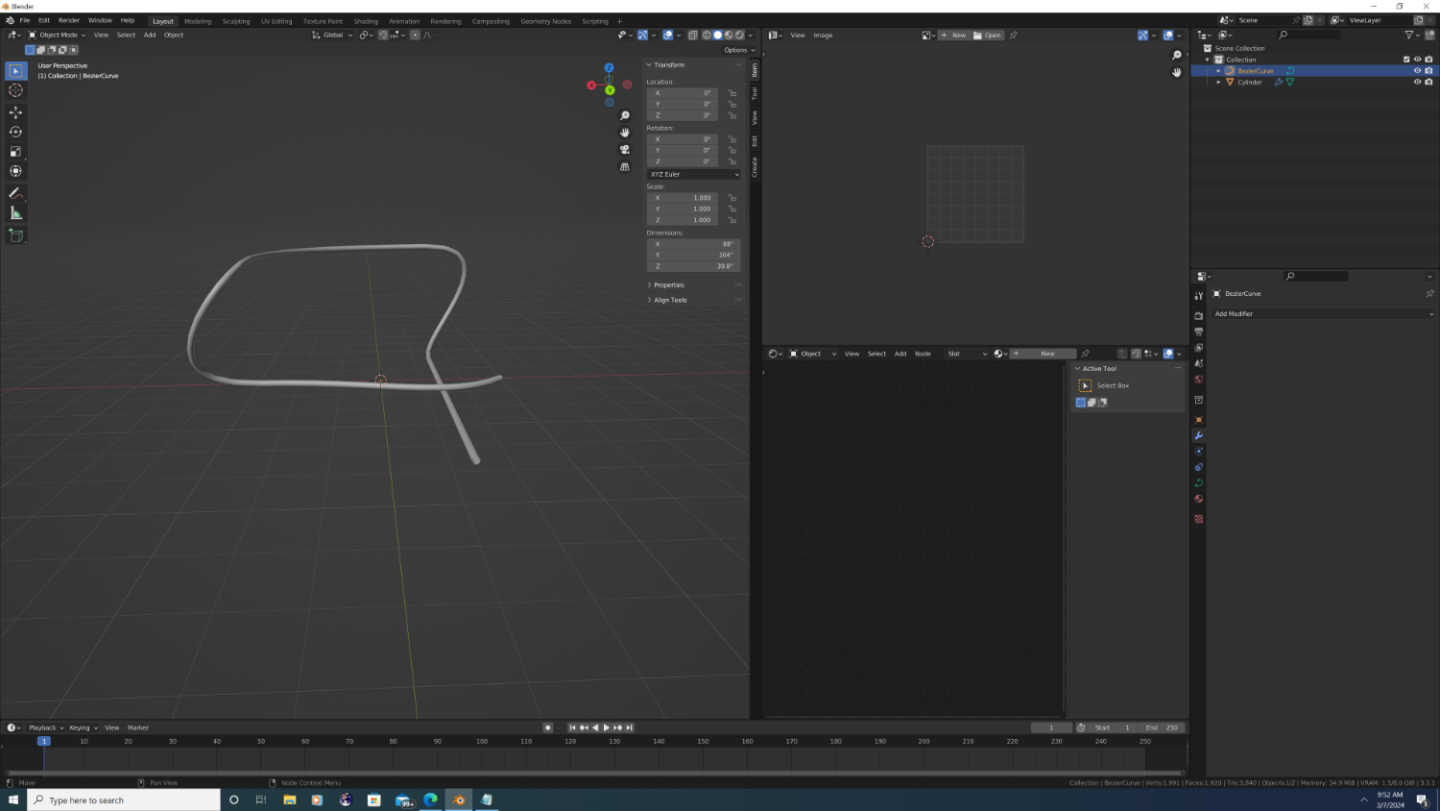
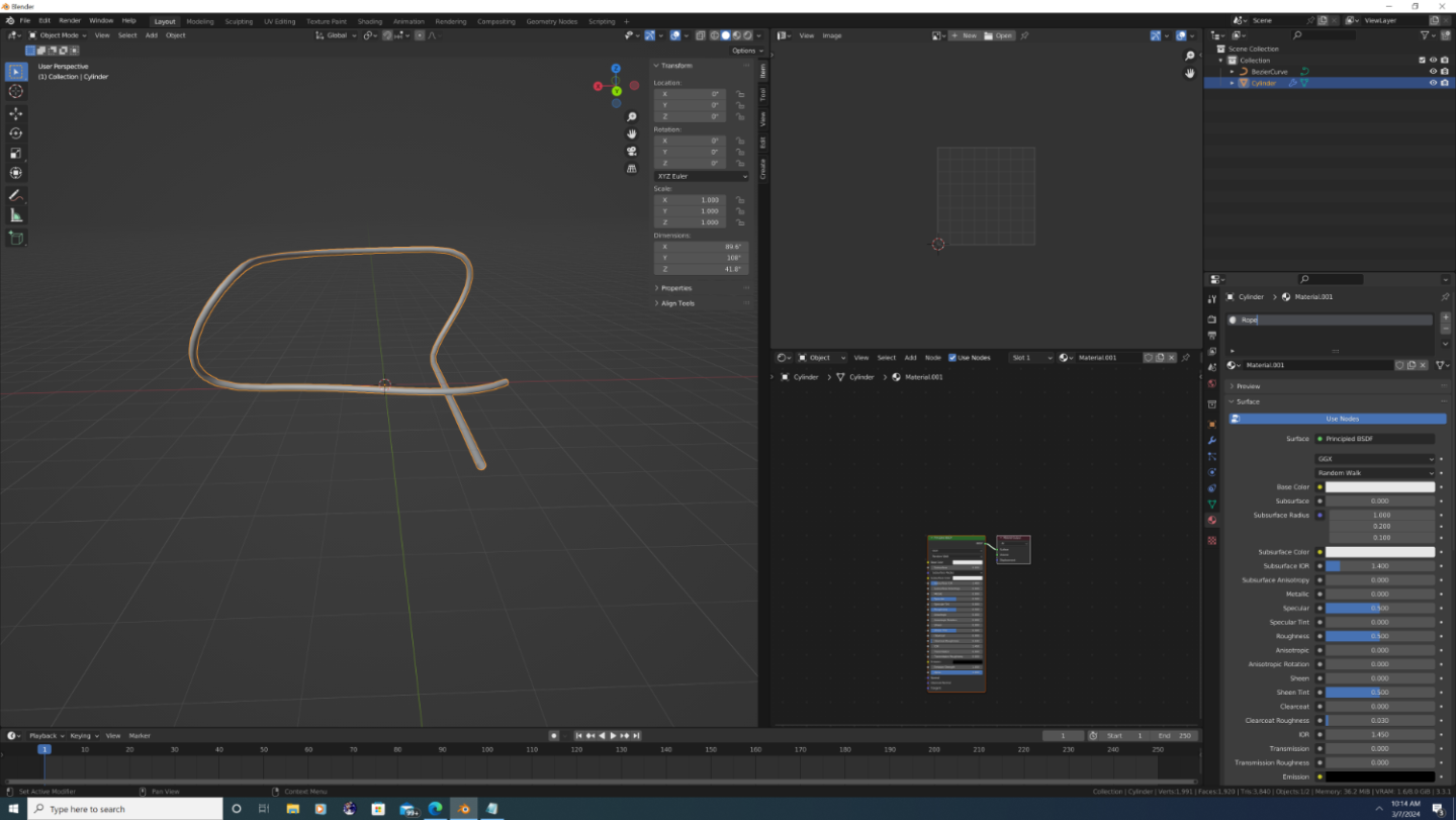
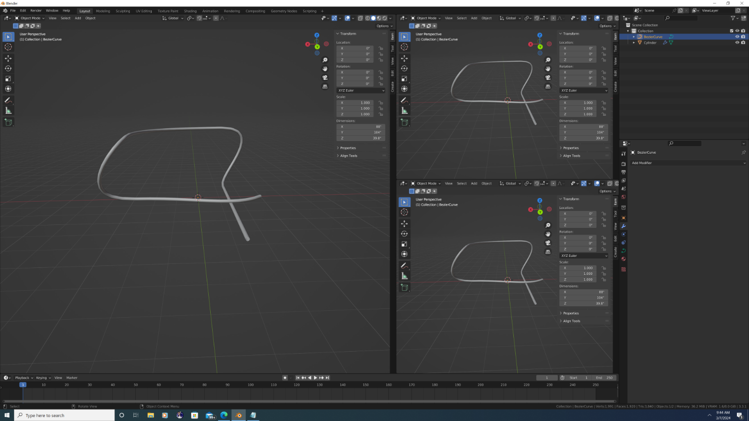
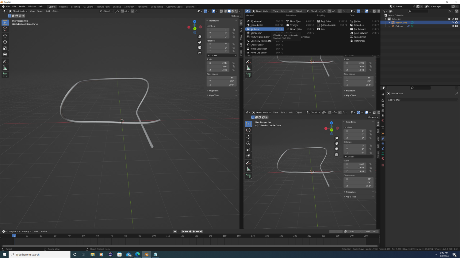
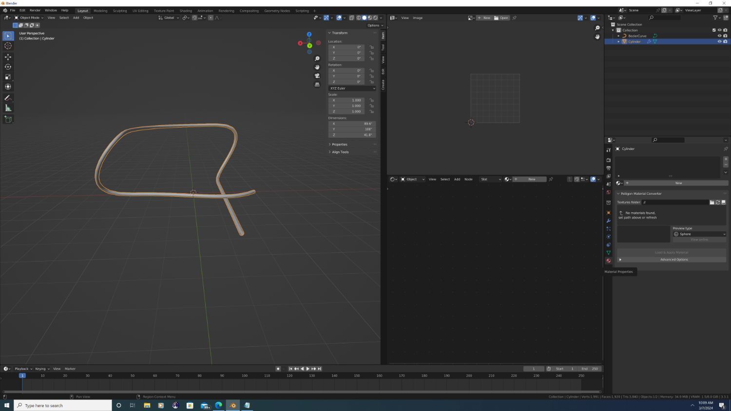
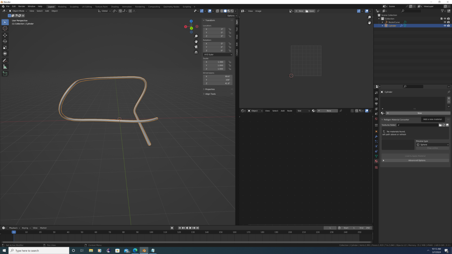
3D Ropes in Blender - Part 3: Textures Welcome back everyone. In this part of the tutorial, we will texture our rope using textures from the poliigon.com website (no affiliation). Here's the link: https://www.poliigon.com/texture/fabric-rope-001/2339 Disclaimer: The images for this material were at one point offered for free, but I cant say for certian if they still are, as it just shows 'purchased' under my account. When I got them they also came with an unrestricted license, so DM me if you want me to share. That said, please consider checking out the other textures on the site and supporting the creator if you like them. Like all things in blender, materials and texturing are a rabbit hole in-and-of themselves. So if you are completely new to this, please check out my [now abandoned] texturing tutorial here: When doing ropes, it's best to texture your rope segment before applying the array and curve modifiers. Why? Because you only have to do it once! Provided you use tileable textures and you correctly UV unwrap the rope segment (cylinder object), you can duplicate it for each curve on your ship, and the ropes will always look good. Step #1. Workspace Windows First, let's setup our workspace. By default, blender looks something like this: In addition to the 3D Viewport, Outliner, and Properties panels, we need to see the UV Editor and the Shader Editor. How you arrange your workspace is completely up to you, but if you hover your mouse at the corners, the cursor will turn into cross-hairs, allowing you to split the screen into additional windows, like so: and after... We obviously don't need to see three of the same thing, so let's change the top-right workspace to be the UV editor, and the bottom-right workspace to be the shader editor. To do this, click on the top-left most icon in the windows, and select the UV editor and Shader editor from the drop-down, respectfully. then... and after... Tip: hover your mouse somewhere over the Shader Editor window and press 'N' to hide the Active Tool sidebar - we won't be needing it for this tutorial. Step #2. World Lighting Add some sort of light to the scene via the 3D viewport, or toggle the Object/World lighting dropdown in the Shader Editor to setup environment lighting. I'll be using an HDR with Cycles rendering, but the setup of that is beyond scope of this tutorial. Failing that, Look Dev mode comes with some HDR's built in, but Look Dev is worse than Evee in showing the result of our work here. Step #3. Create a New Material Okay time to setup our rope texture in the shader editor. First, click on the cylinder to select it, then click on the material properties icon in the Properties Editor panel (the red checkered ball icon, 2nd from the bottom) Click on the bar with the word 'New' in it to create a new material. Then, triple click on the 'Material.001' that gets added to the list to rename it to 'Rope', like so: Note that there are now two new boxes in the shader editor. We are now ready to import our image files into the shader editor and create our rope material. FYI - I'm going to break off here and resume with step #4 in the next post. Best, -Nate


-
3D Ropes/Rigging in Blender
3DShipWright replied to 3DShipWright's topic in CAD and 3D Modelling/Drafting Plans with Software
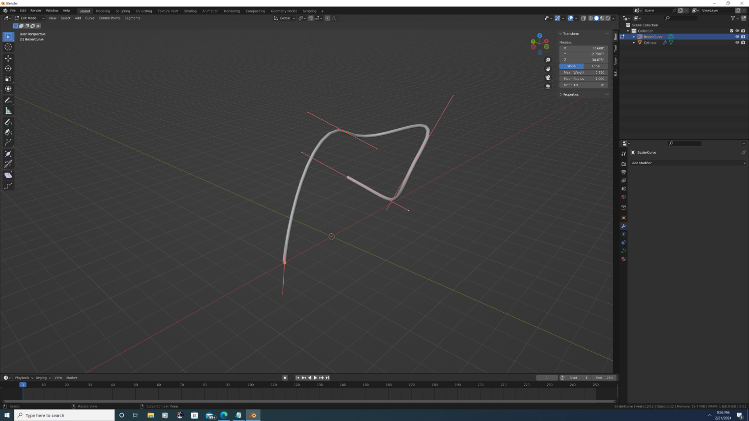
TUTORIAL ERROR FIX: Forgive me, but I left out one detail: If you followed the above instructions, your rope likely looks a lot thicker than mine. This is because when we scaled up the curve segment, the mean radius was turned up to 3, even when we applied all transforms. To fix this, select the curve, tab into edit mode, and press 'a' to select everything. In the properties panel (upper right-hand corner), change the 'Mean Radius' back to '1'. That should fix the problem. -Nate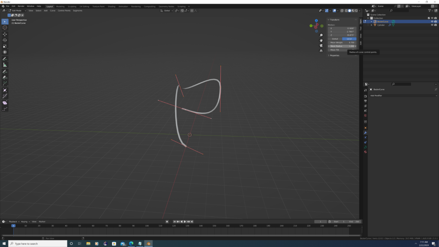
-
3D Ropes/Rigging in Blender
3DShipWright replied to 3DShipWright's topic in CAD and 3D Modelling/Drafting Plans with Software
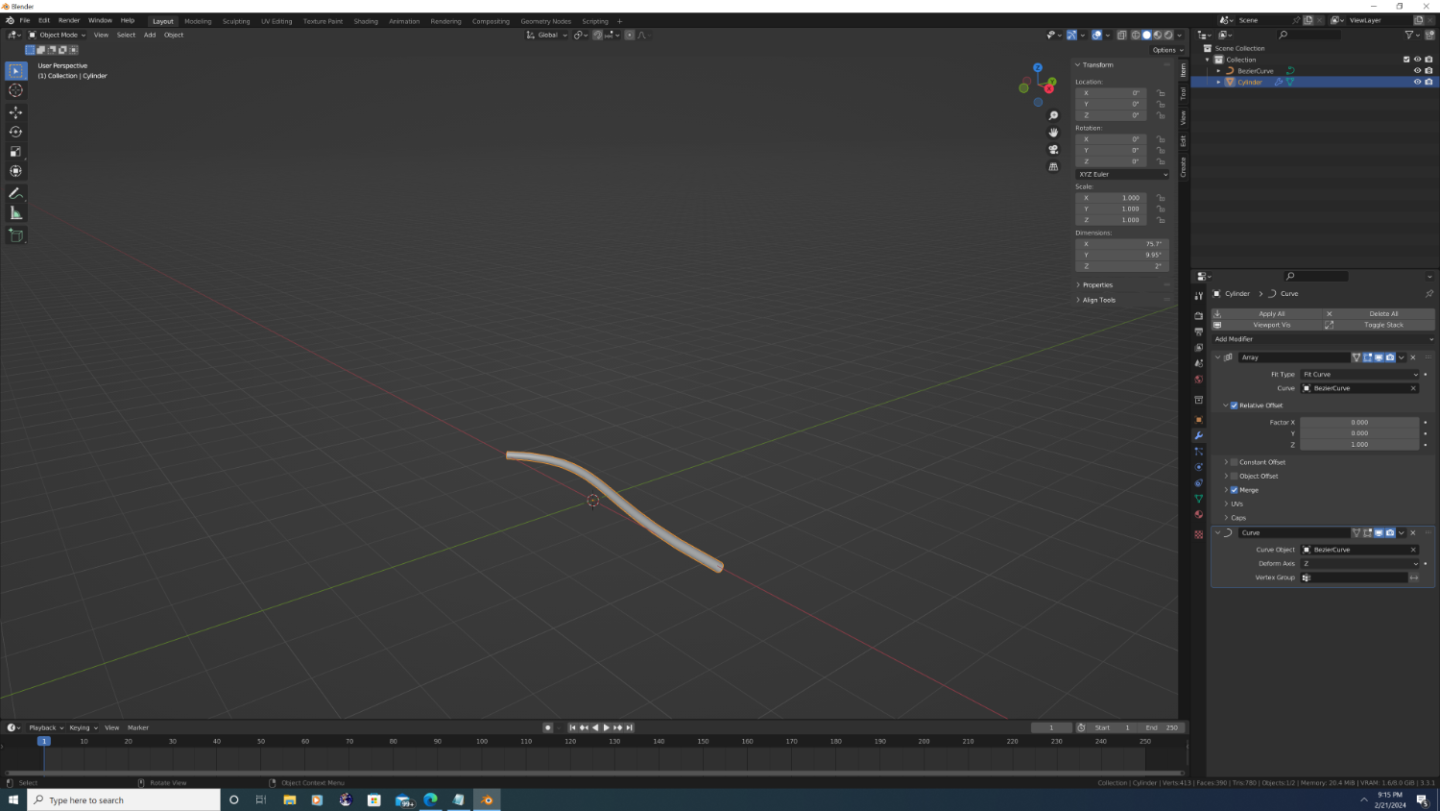
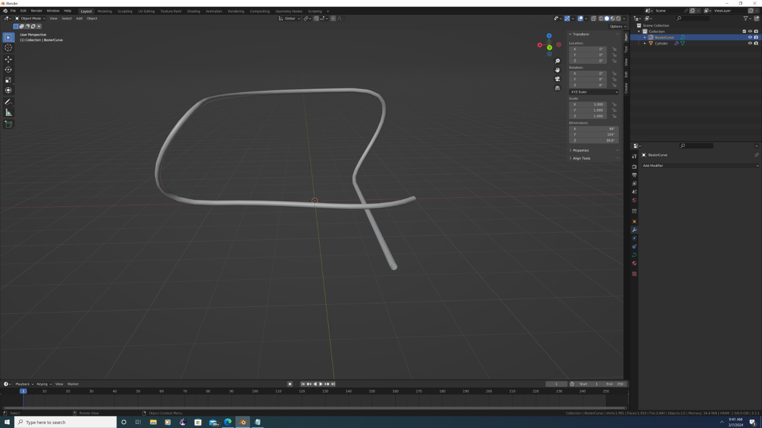
Part 2: Let's make a Rope (Finale) The last step in the process is to add a Curve Deform, or simply 'Curve modifier to the rope object. So go back to the modifier stack and add a new modifier and find 'Curve' this modifier is super simple and there are only three settings options, of which we only use the first two: Curve: Use the eyedropper to select the curve object. Jumping ahead here, but it's important to call out that both the array and the curve modifiers must reference the SAME curve object to work properly. Pairing the array and curve modifiers to the same segment might be easy when there's only one rope and one curve but it gets confusing quickly on a ship. Thus its always good to have a specific naming scheama. Deform Axis: Set dropdown to 'Z' And that is the basic process in a nutshell. The next tutorial will cover texturing, then we will get into the difficult part after that, which is manipulating the curve path to where you want it. Like I said in the beginning, the challenging part is getting the curve. But for now, enjoy! Play around with the curve by tabbing into edit mode and dragging the handle around, or press 'e' to extrude a new segment. Till our Next! -Nate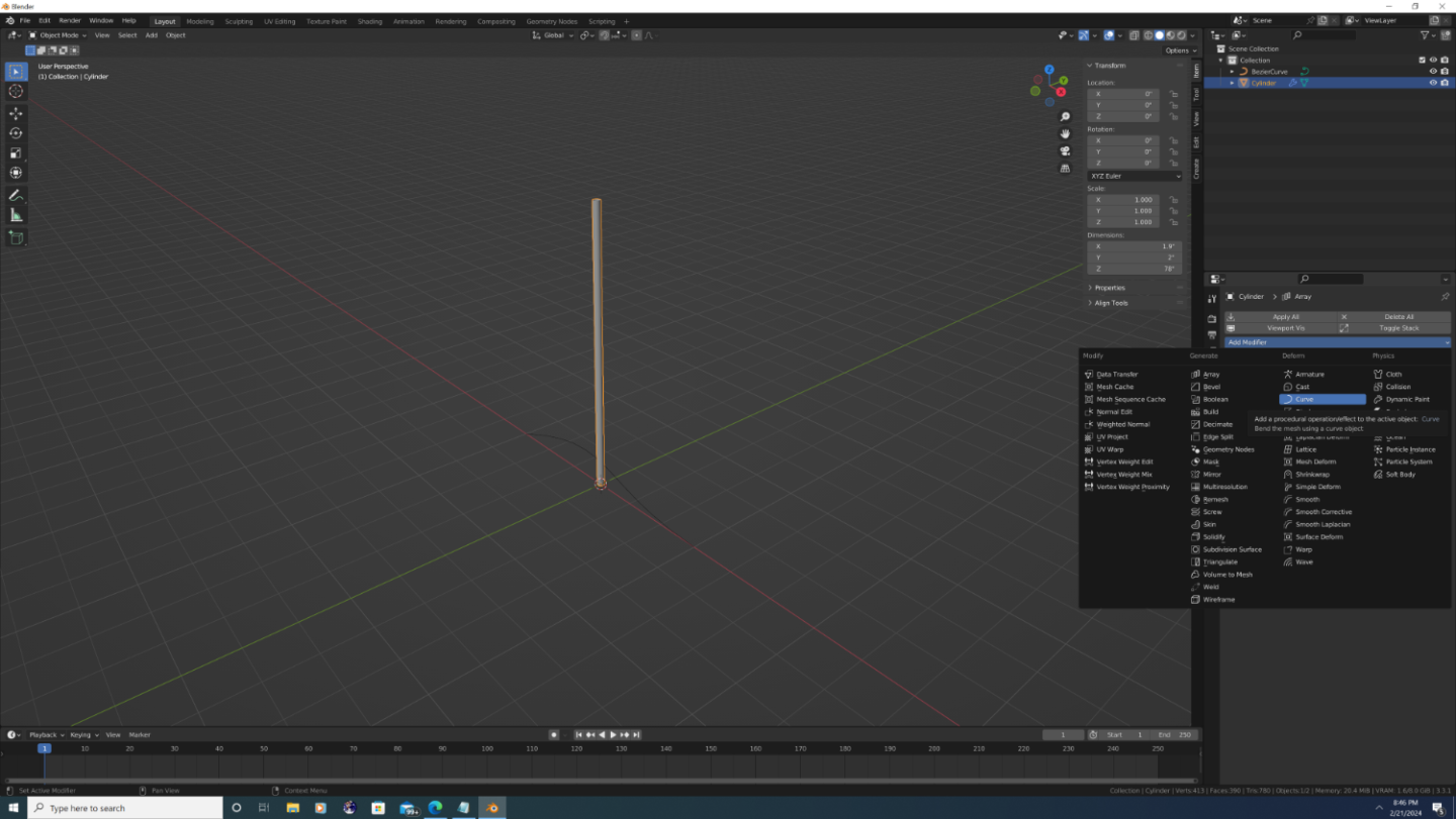

-
3D Ropes/Rigging in Blender
3DShipWright replied to 3DShipWright's topic in CAD and 3D Modelling/Drafting Plans with Software
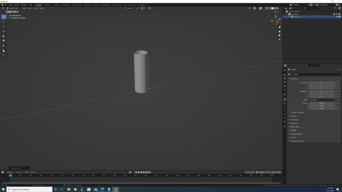
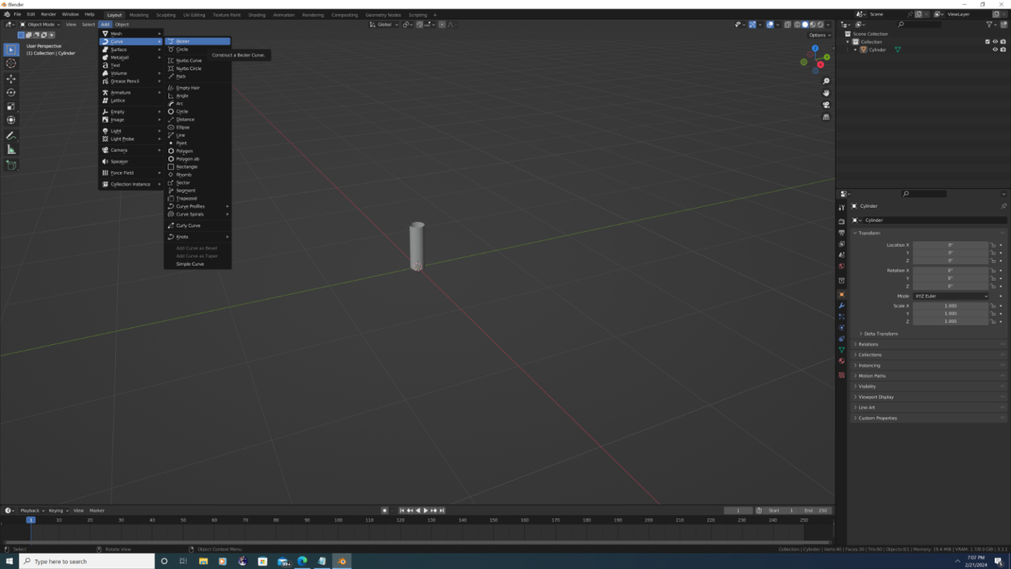
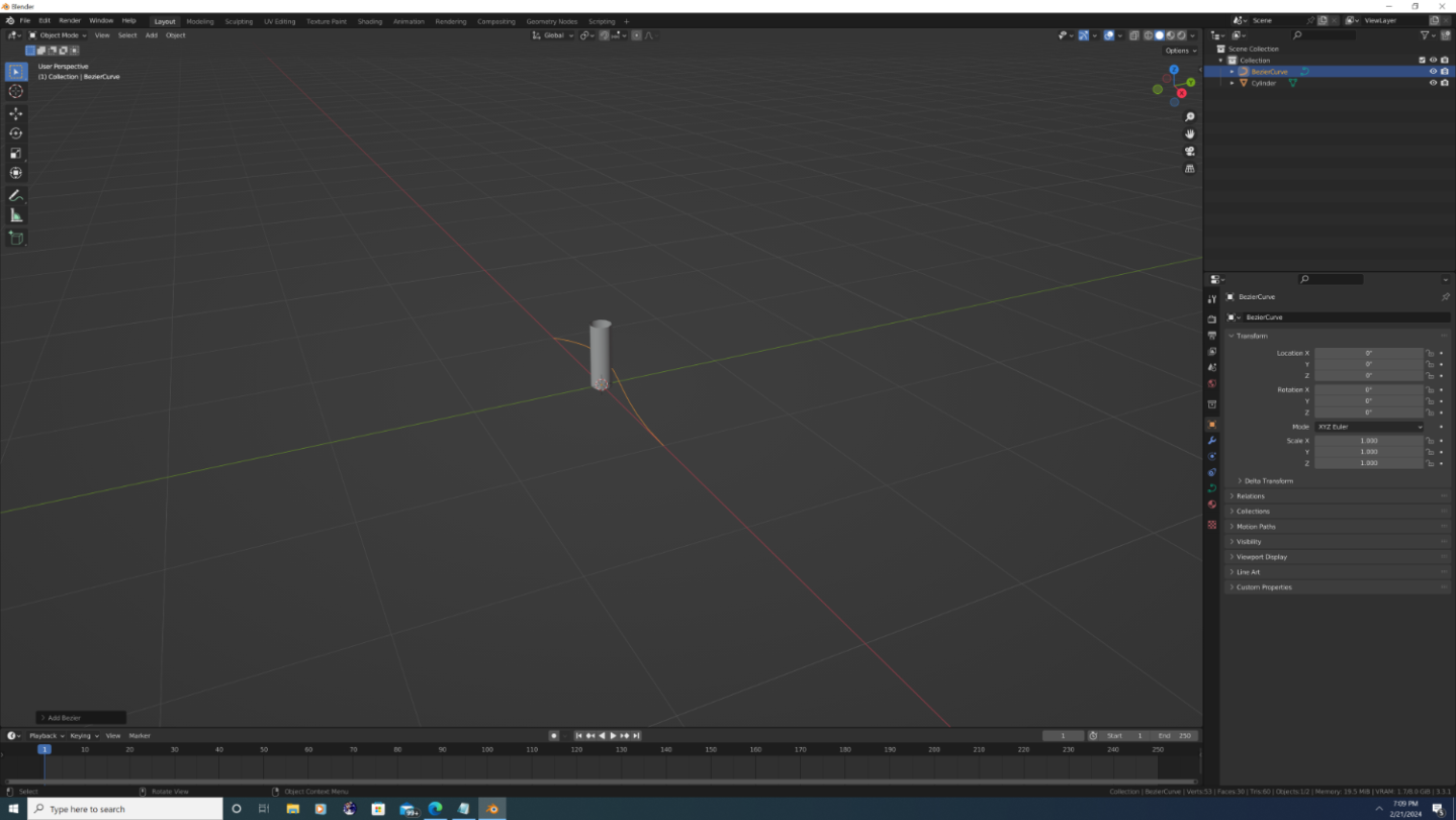
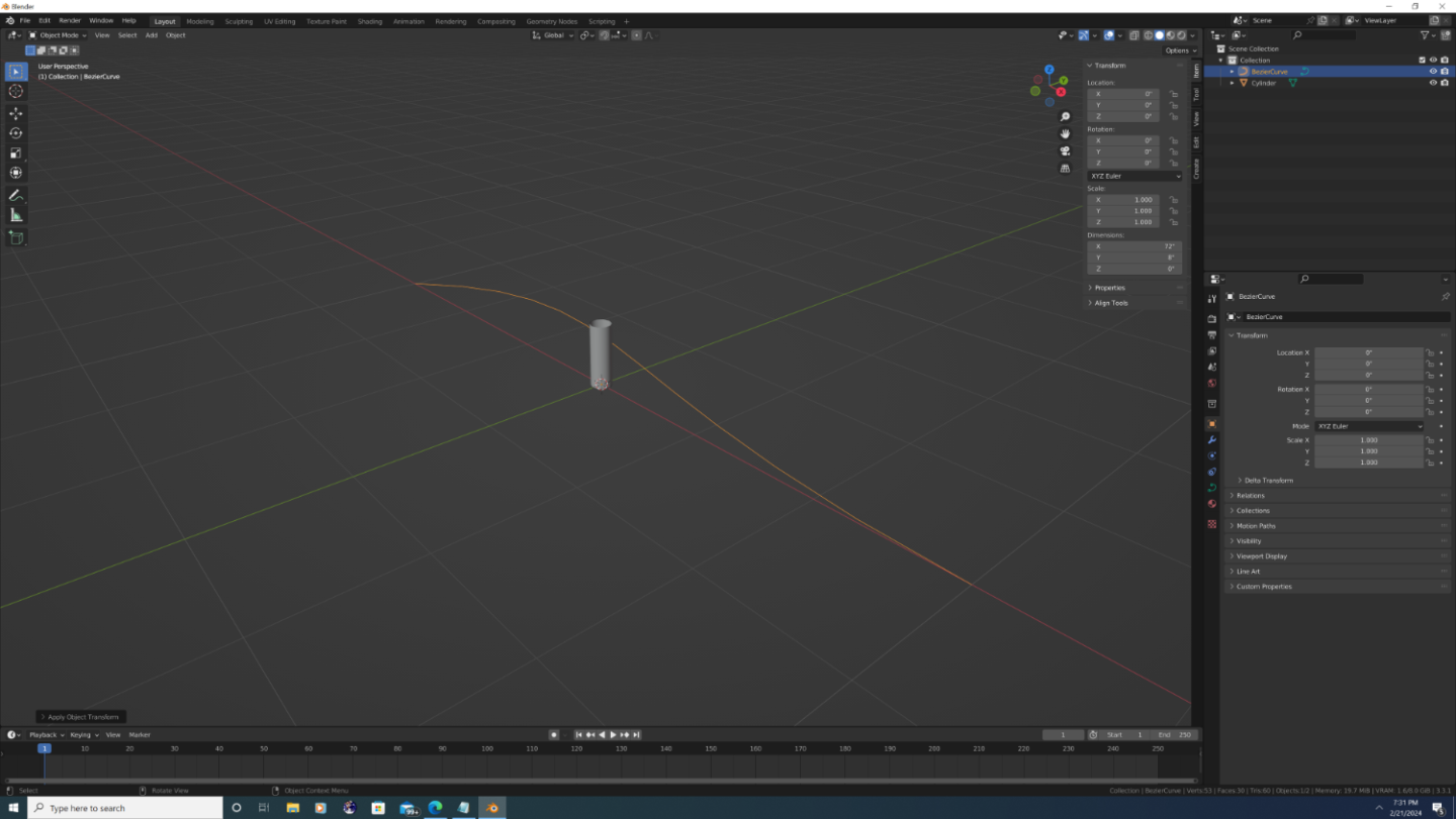
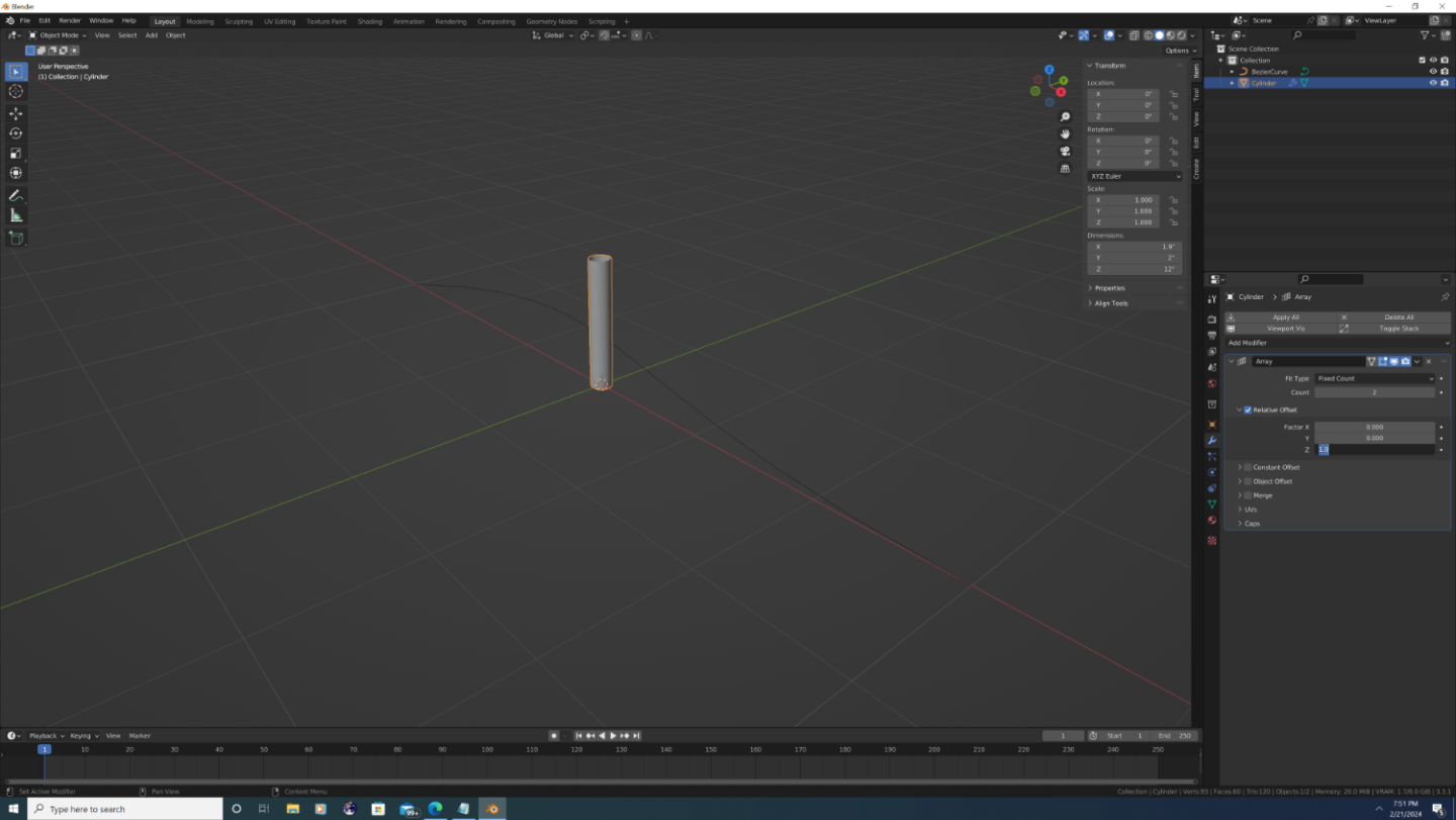
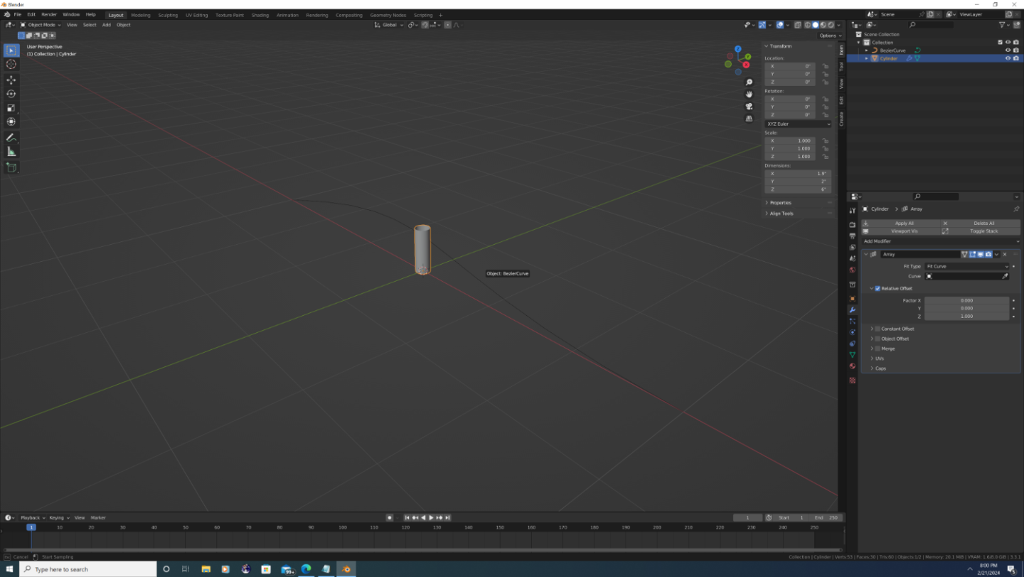
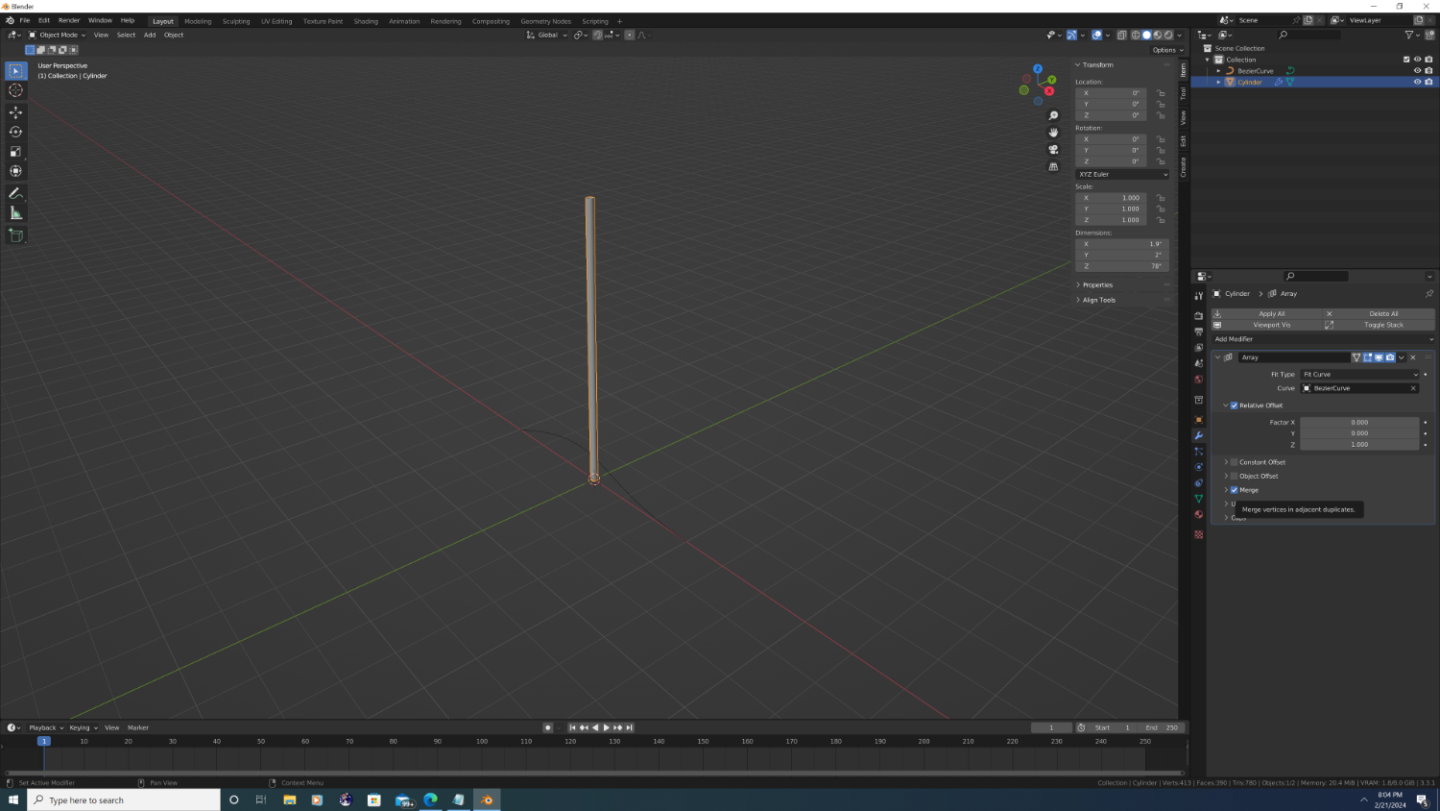
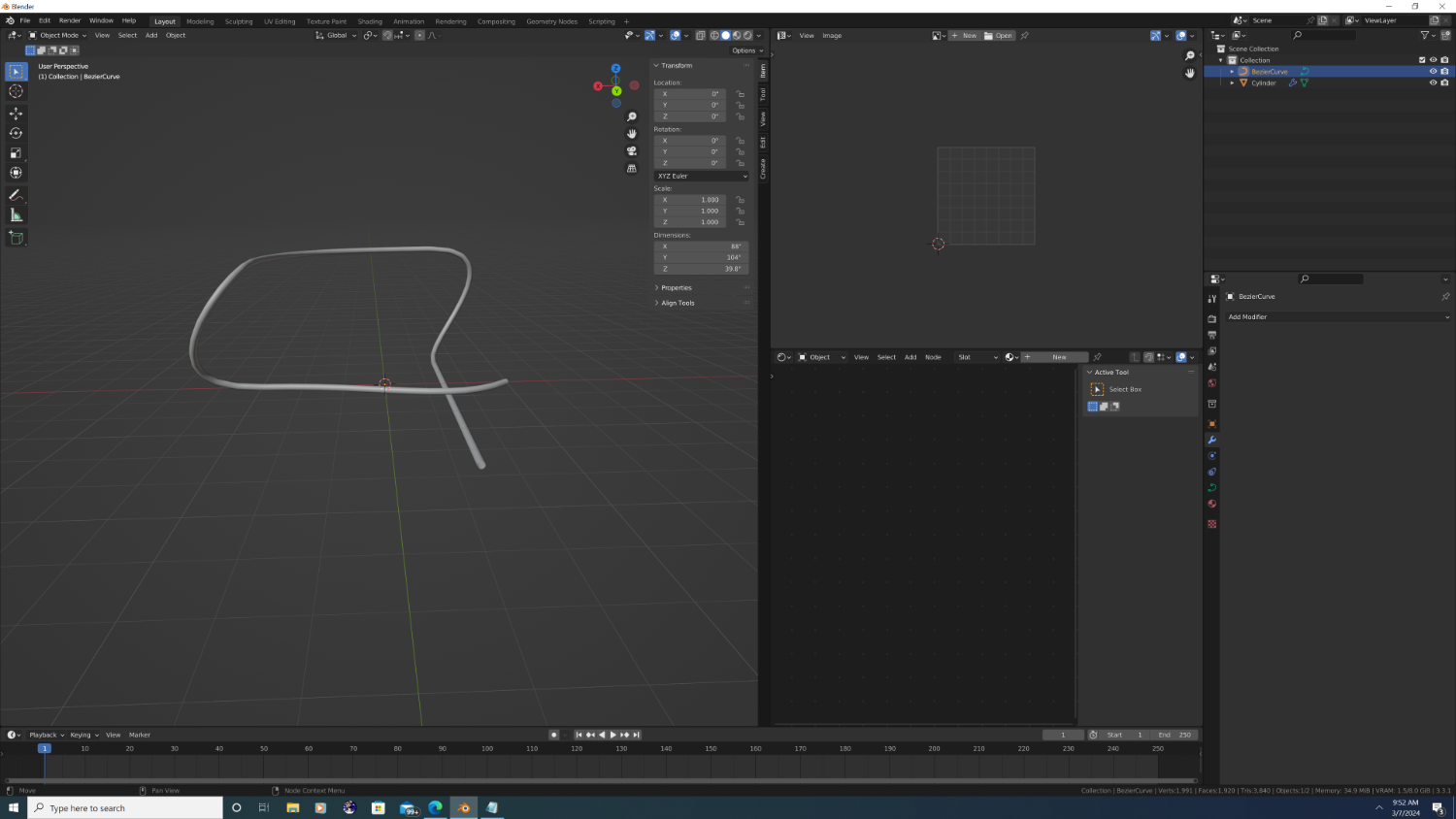
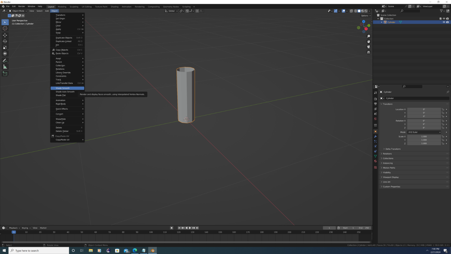
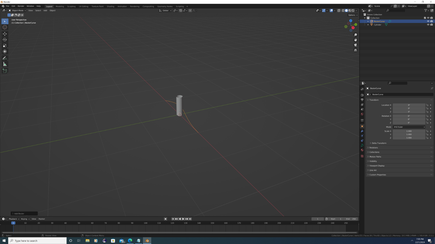
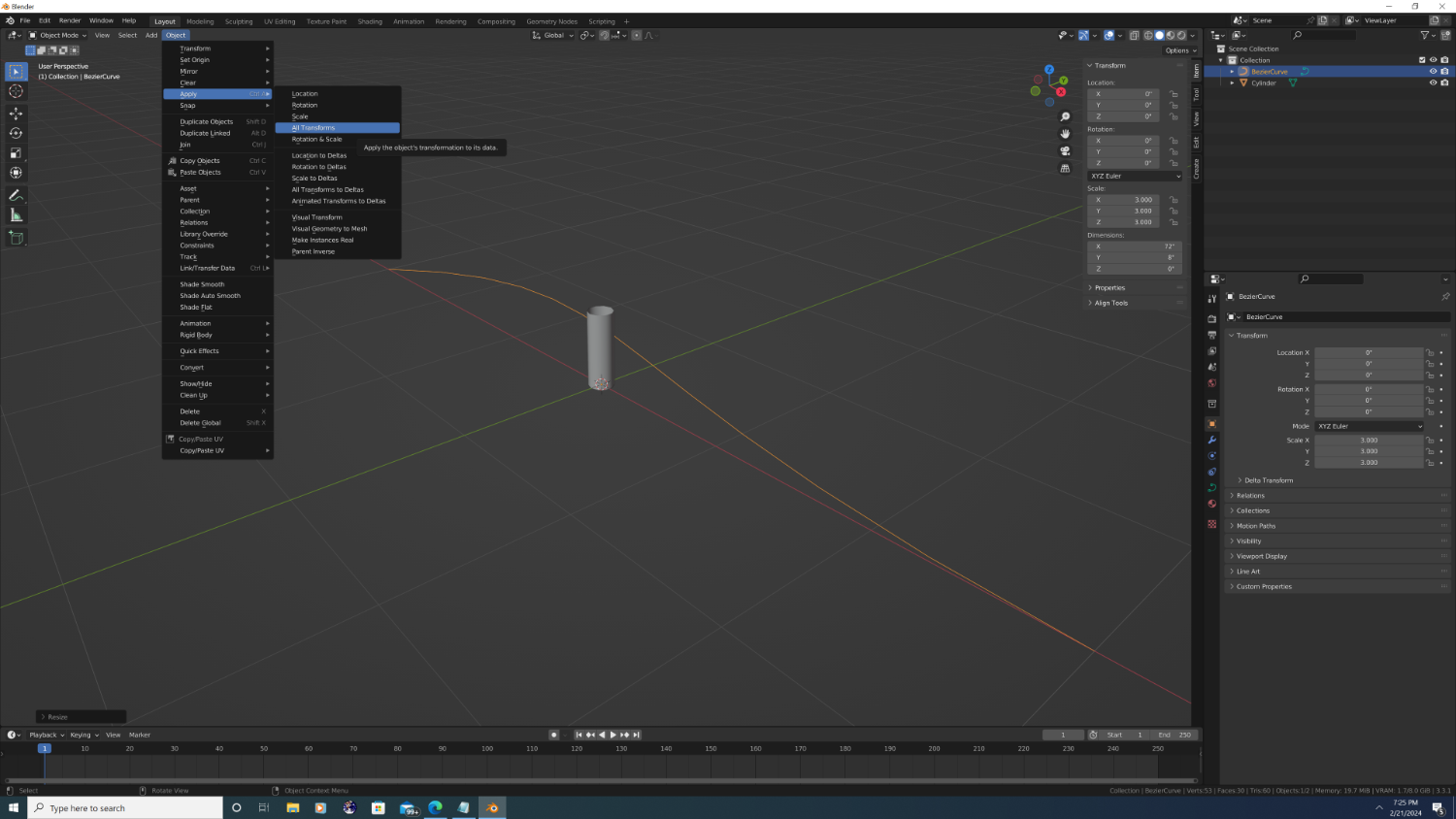
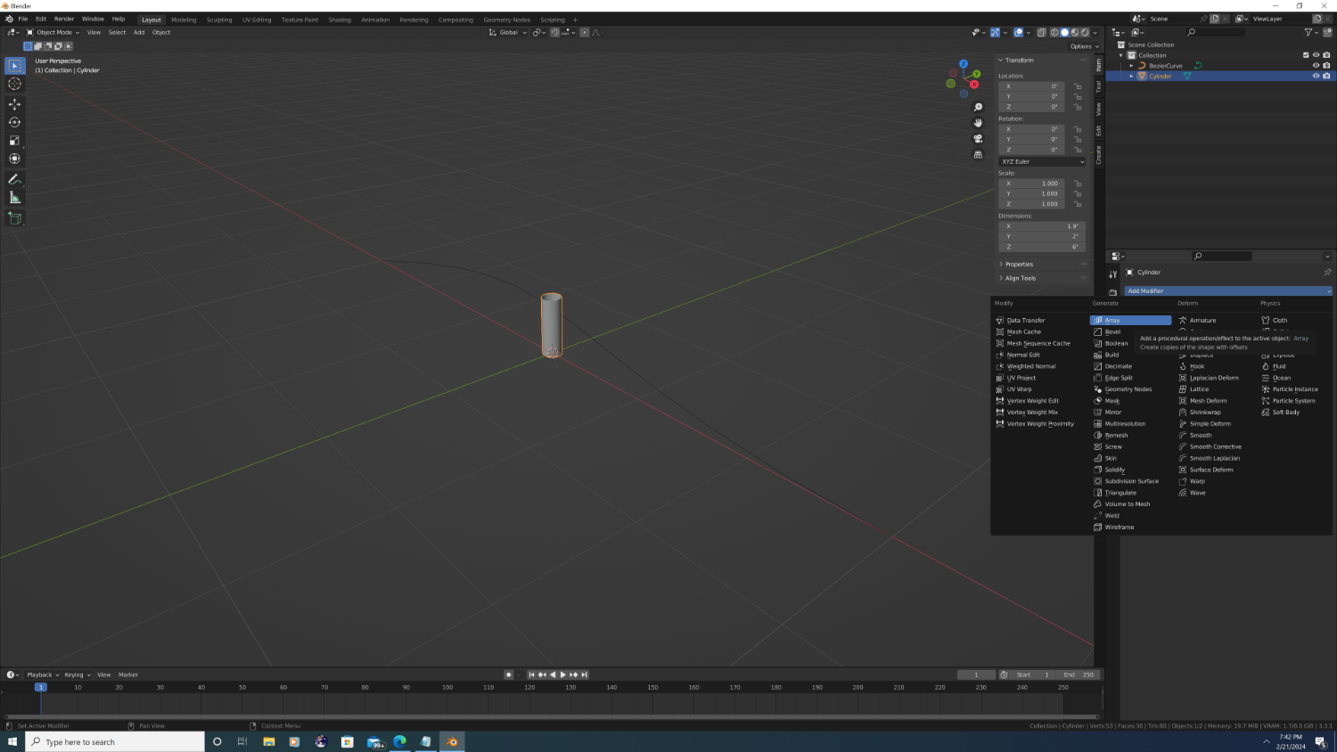
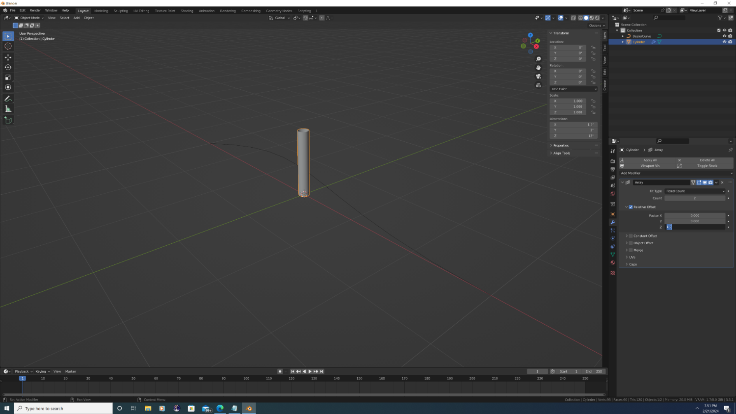
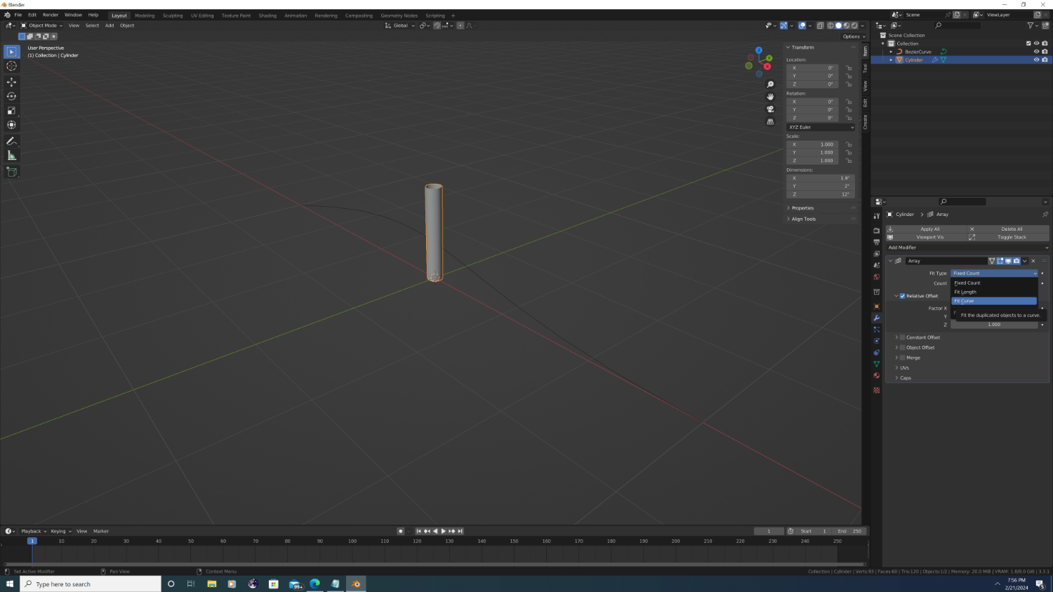
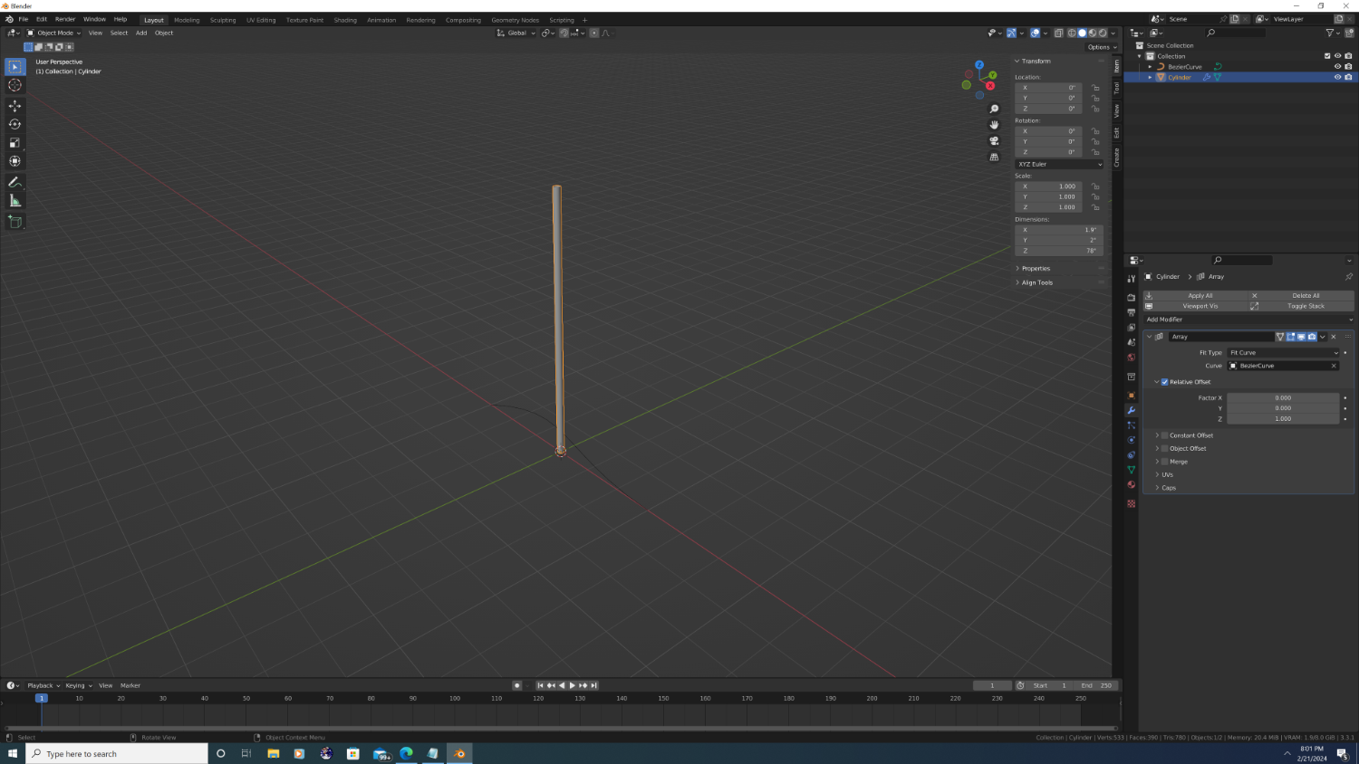
Part 2: Let's make a Rope (Continued) step 3 (Cont.) Okay, so we left off having just made our loop cuts, like so: With that done, tab back into object mode and for the sake of appearance, lets go ahead and shade our cylinder smooth (object -> shade smooth). Note: we want to use full smooth here and not auto smooth. (yes, we could've shaded the faces smooth in edit mode, but for the sake of memory later on, we don't want each rope object to use custom split normals) and after... Step 4. Add a curve. Go to add -> curve -> bezeir curve. I'm adding a bezier curve because the default squiggle that appears is a good shape to illustrate how the rope modifiers work. In truth, it doesn't really matter which type you choose, as everything can be changed later. Anyway, here's our curve: and after: To see the full effect of what we're about to do, I want the curve to be a bit bigger, so press 's' for scale then press '3' to make the curve 3x larger (3 is arbitrary, pick any value you want). Now, before we go back and add the modifiers to the rope segment, it's important that we apply all transformations to our curve. If you ever find that your rope is way off in the middle of nowhere and not following the path, the most likely culprit is that transformations (location, rotation, or scale was not applied) Anyway, go to object-> apply -> all transforms. and after... (tip: 'n' is the hotkey that toggles the properties menu) Step 5: Add the array modifier to the rope segment. To do this, click back on our rope segment to select it, then go to the modifiers panel. Look for the blue wrench icon and click on it. Then add an array modifier (th UI is slightly different in later versions of Blender, but I believe you can either type to search for it, or find it under the 'Generate' category) The good news is Blender uses a relative offset by default which is what we want, but the bad news is it defaults to the x-axis, whereas we want to 'stack' the rope on the z-axis. Easy enough to fix, however, just replace the number '1' with '0' in the "Factor X" box then type '1' in the "Factor Z" box like so.. There are 2 more settings we need to adjust. First, look at the initial dropdown box that allows us to select the 'Fit Type'. We want Blender to automatically calculate how many segments are needed to fill our curve, so click on the dropdown and choose the 'Fit Curve'. and after... There is now a text box titled 'Curve' that allows us to tell Blender which curve to use, and - my favorite feature here - it comes with an eye dropper tool. Click the eye dropper, then click on the curve in the main window, like so... and after... Lastly, check the 'Merge' box to make it active or your poly count will run way high! Continued in next post...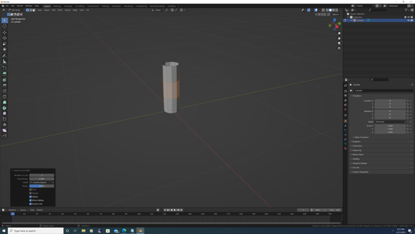


-
3D Ropes/Rigging in Blender
3DShipWright replied to 3DShipWright's topic in CAD and 3D Modelling/Drafting Plans with Software
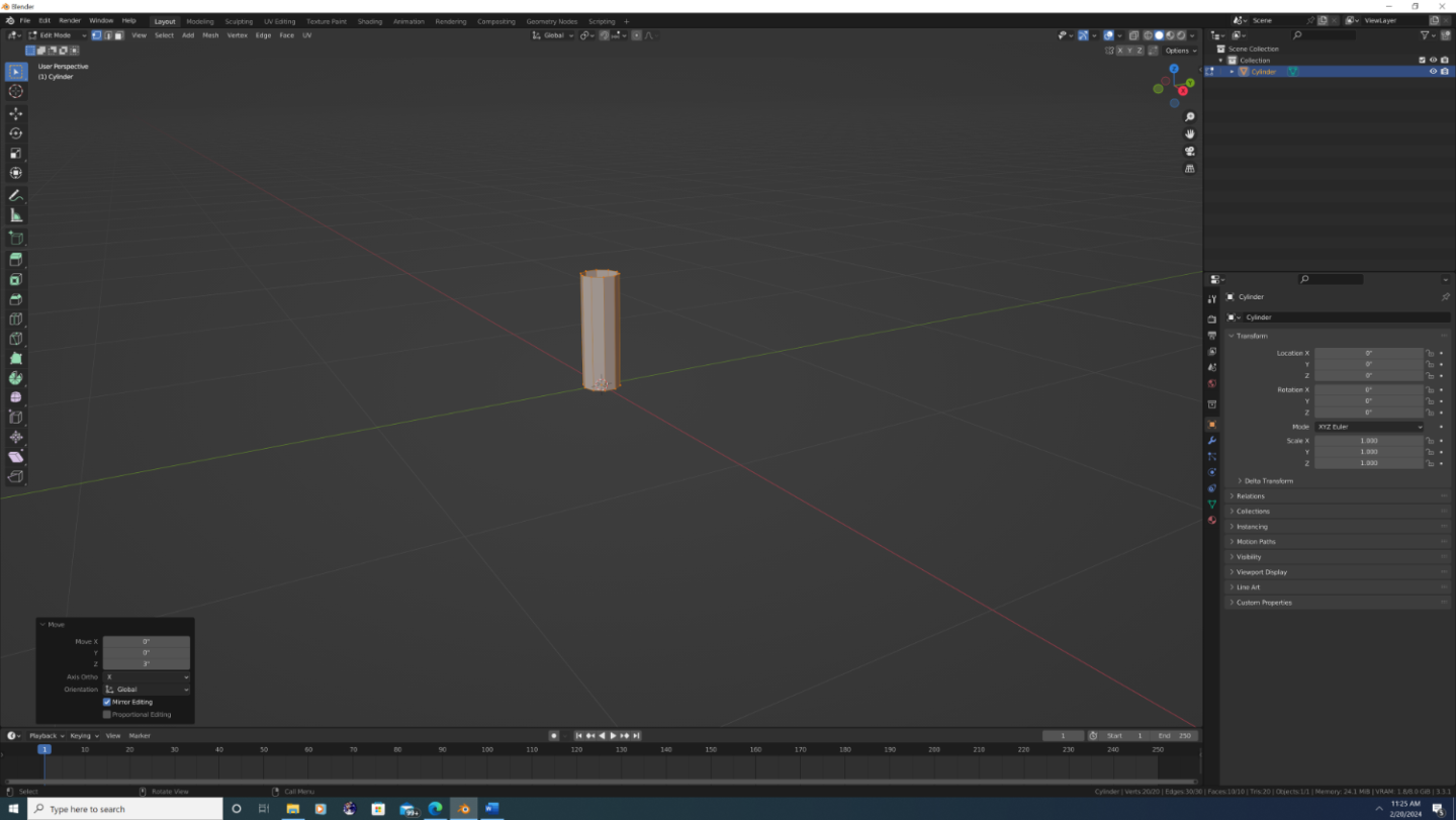
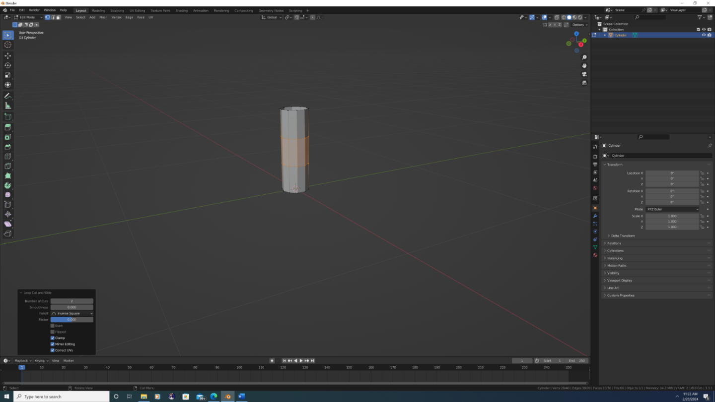
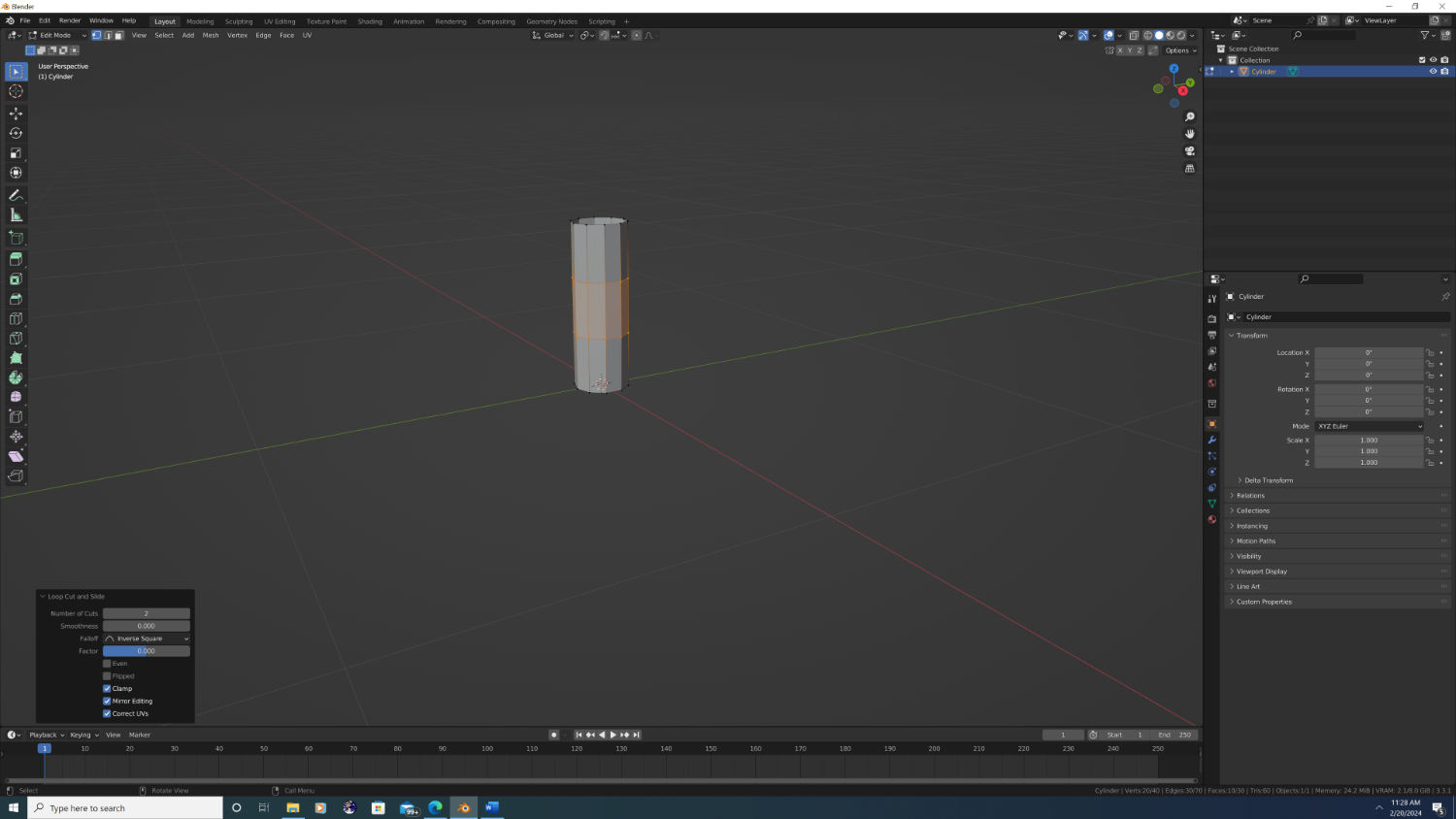
3D Ropes in Blender - Part Two: Let’s make a rope! The easiest way to explain this workflow is with an analogy. Imagine that we are making a candy necklace out of cheerios. In real life, you would cut a piece of string to the right length, then begin fishing cheerios down the line until there was no more room, at which point you tie the necklace behind your neck, and Bob’s your uncle! Blender works just like that, except you position the string first, tell Blender to calculate the exact number of cheerios you need ahead of time by stacking them on top of one another, and then put them all on the string at once. Step 1: Clear some space! Open Blender and start a new project or hide everything on your existing project so you have a blank workspace. Note: This first tutorial is going to be a throw away, so there won’t be anything you’ll want to port over as a final product anyway. Additionally, I like to keep things in approx. real-world scale, even for basic stuff so I changed the units to imperial (I’m American – don’t hold that against me, lol) and set the scale to inches. Step 2: Add a cylinder. Add -> Mesh -> Cylinder. When the cylinder is added, expand the “Add Cylinder” pop-up box at the bottom left of the view port and type in the following settings: Vertices: 10 The more vertices, the more cylindrical the rope will appear at close range, but exponentially greater poly cont. Name of the game here is low poly. Honestly, 8 or even 6 is fine for smaller diameter ropes. I only use 10 on the thickest lines, such as anchor cables and main stays. Radius: 1 in. Depth: 6 in. I’ll explain why in a moment, but the rule of thumb is that any rope segment should be 3x longer than it is thick (dimeter). Since the radius of a circle is ½ the diameter, a segment with a 1in radius needs to be 6in in length (Blender calls this depth, since blender generates cylinders with the flat faces oriented on the top and bottom). Cap Fill Type: Nothing Because we are going to be stacking the segments, we really want is a bunch of hollow tubes rather than enclosed cylinders. After all cheerios have holes in the middle! Step 3: Tab into edit mode, press ‘a’ to select all vertices and ‘g’ to grab/move, then ‘z’ to restrict movement to the z axis, then hit the number ‘3’ to move the whole mesh up by 3 inches (basically, we want the bottom most vertices flat on the virtual ground at location z=0). Now Loop cut it twice by pressing 'ctrl' + '2' then hit 'enter' (this will allow the segment to bend around the curve better).thumb.png.5181def61426ed15fc146ee4b31b77c4.png)
.thumb.png.b5ca2ae05268777fd39d8d5dc7004ee0.png)
-
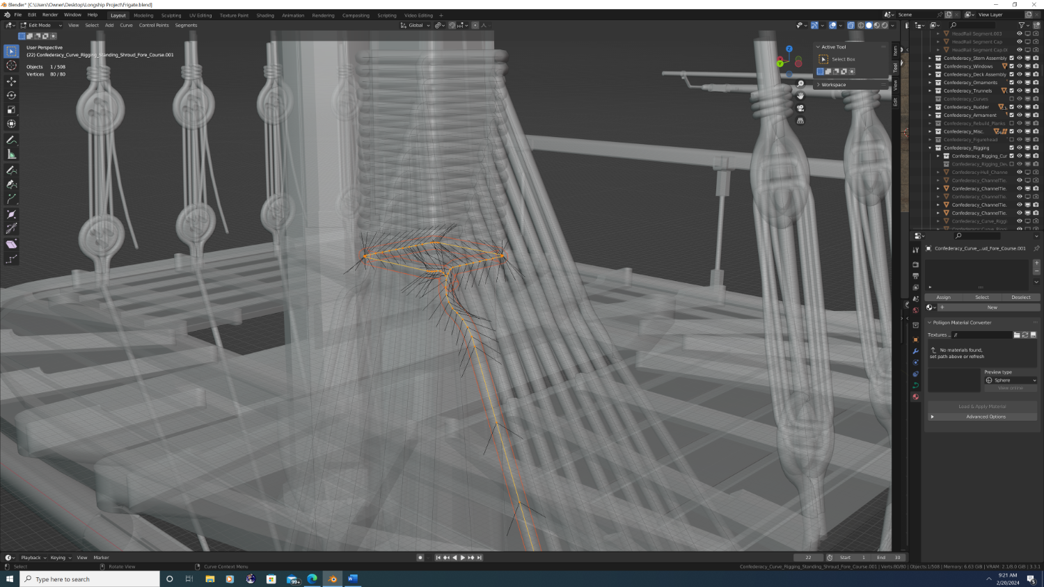
3D Ropes in Blender - Part One: First Things First Preamble and a Humble Plea Hi everyone. I’ve received a few requests to demonstrate how to do ropes/rigging in Blender. Admittedly, I’ve been dragging my feet.. for the better part of a year! Attempting to put it all down in writing is a bit like opening Pandora’s box. There are just so many different aspects of this that can be done differently based upon personal preference, CPU/GPU performance, and use case. I think the most helpful is to share my personal preference, my chosen approach - and rather than defend or compare it to alternatives - quickly get into the tips and tricks I use to adapt these processes to Age of Sail ship rigging. My humble ask of any experienced 3d artist reading this topic would be: let’s try to avoid any of the ‘why not do it this way’ conversations in this thread [dm’s always welcome]. I’m always open to learning new things, but there are very good reasons I do things the way I do in Blender, even if they’re not always seemingly efficient. Aside from which, there are certain cans of worms I’d rather not open for the sake of the newbie’s trying to follow along. Thank you all and here we go… The Concept There are two (2) fundamental methods used to create ropes in Blender. Both methods, which I will cover in a moment, have the same components: A path in 3-dimensional space that the rope will follow. In Blender, we will represent this path using the curve object. For example: The path of a shroud line a ship begins around the upper deadeye at the channel and end curled around the lower mast head. A mesh or model of the rope itself. A texture for the rope. Figure #1. A transparent view of the main shroud lines as they pass through the lubber's hole and wrap around the mast head atop the bolsters. The curve object (yellow line with orange vertices) acts as the path for the rope mesh (dark orange) to follow. The arrows indicate the direction of travel and the tilt of the curve. Method #1: Create Ropes Directly from a Beveled Curve Workflow: Create the path using a curve object -> Bevel the curve to create the rope’s mesh -> Texture the mesh NOTE: I do not use this method, and thus am only loosely familiar with how it works. However, I believe @Kurtis used this method, so perhaps he can assist if anyone’s interested. Method #2: Create Ropes Using the Array and Curve Deform Modifiers Workflow: Create a rope mesh segment -> Texture the mesh -> Create the path using a curve object -> Assign the segment to the path (curve) using the Array and Curve Deform Modifiers NOTE: The second method is what I will be using for the remainder of this topic/thread. Now let’s open blender and make our first rope! @CDR_Ret

-
Very nice! So forgive my ignorance but how is the game set up: do the models you import only appear once (example: USS Constitution), or are you essentially importing a class of ship from which the game will spawn multiple instances (example: a 44-gun Frigate)? Just curious.
-
Hey Martes! So I can't speak to their effectiveness, but the smaller French vessels hold a special place in my heart. Viva le Corvette! Great work bud. QQ: Is it possible for you to bring back some of the old texturing themes you did and mix them in with your newer ones? Just one man's opinion here, but I think some variance among the ships would go a long way towards the immersion factor. For example: if some ships could use yellow and black instead of the white stripe down the gun deck, that would be awesome. Of course, if you have to use only one texture set, keep it as you have it The white, black, and red with yellow at the headrails and stern is still my favorite. Best, -Nate
-
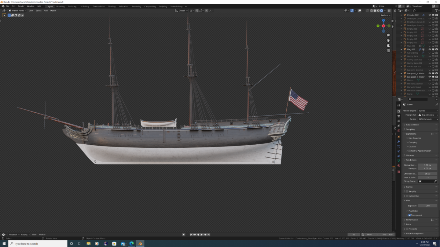
Forgive the repeated topic postings - I think I'm close to finding a 'lossless' image resampling method that will allow you guys to actually see what I see, because sadly, every image I've shared comes out unbelievably blurry... That said, there is hope! I finally bit the bullet and did the scale down in photoshop, so lets see how this goes... @Martes - returning to a topic from long ago, I did some updates to the relief material, and I believe them to be historically accurate. Turns out, they were neither bronze, nor leifed with metallic paints. They were simply the 'sad colours' which your reference material I learned a bit more about. Turquoise-ish color became popular among American ships around this period, because they found that ochres in American soil produced more of a green hue than those in England. I can personally atest to this as, even though I now live in New England, I grew up in the south where lime and real turquoise was abundant (not saying there were literal gemstones in my sand box, but greenish dust was common. But I digress... If you mix everything together the resulting 'sad colour' you [can] get in America is a lot more grey than ochres in England. If you then mix in a little bit of blue paint, you get a material that very closely resembles patina, which captains would use to make their vessels look far more expensive than they actually were.
.png.47f0de7c19832cf8fe66cbf7fe9a558a.png)
- 105 replies
-
- 5
-
-
- Frigate
- Confederacy
- (and 1 more)
-
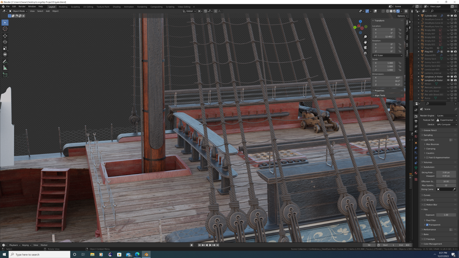
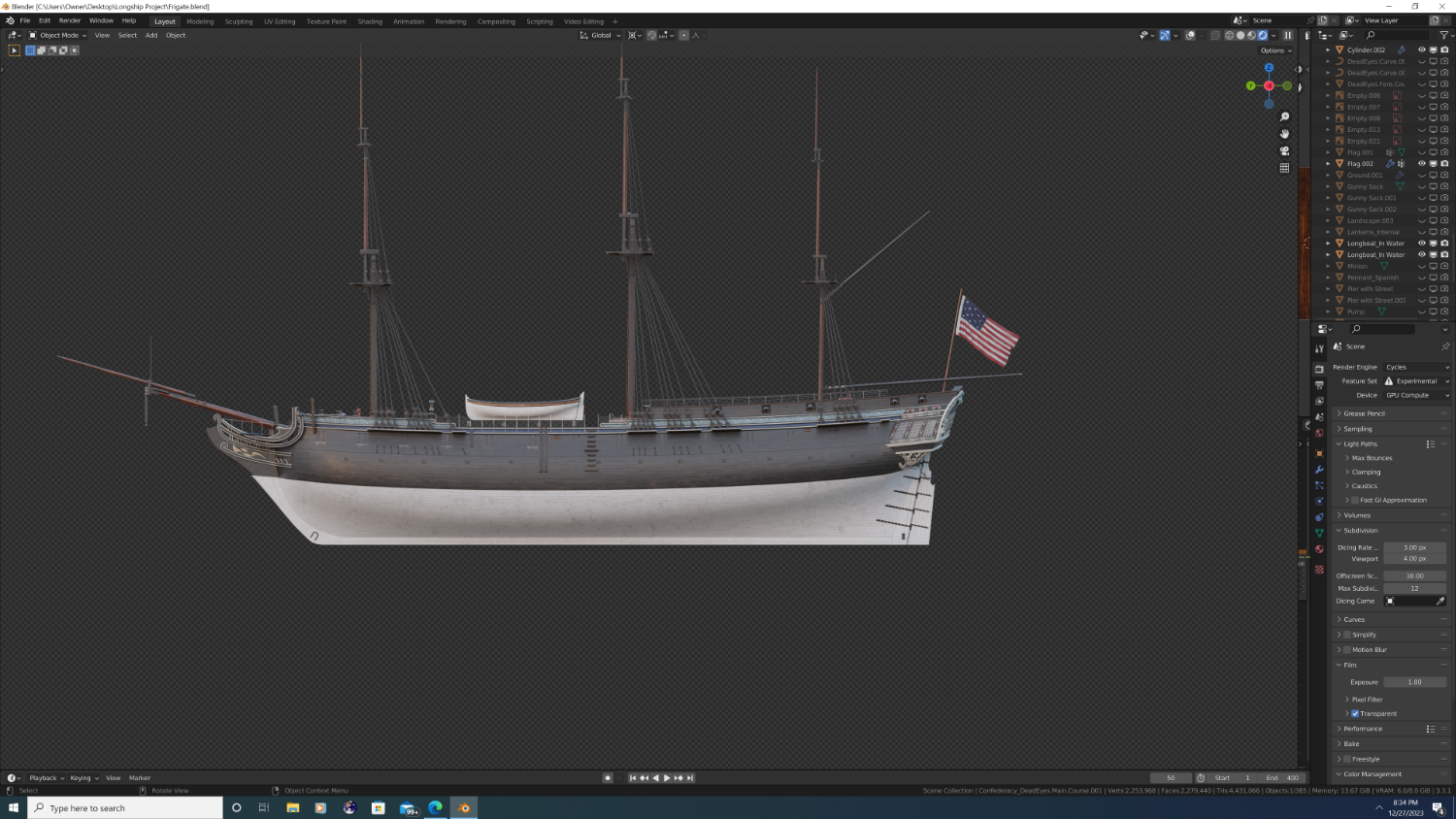
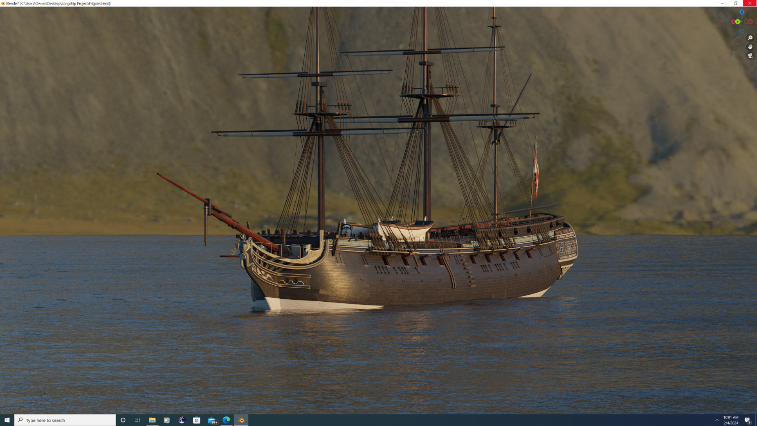
Setting up the standing rigging and getting a preliminary feel for how the yards will look.
.thumb.png.f8c5ce55075ada7b456b8645e86d0bd0.png)
- 105 replies
-
- 4
-
-
- Frigate
- Confederacy
- (and 1 more)
-
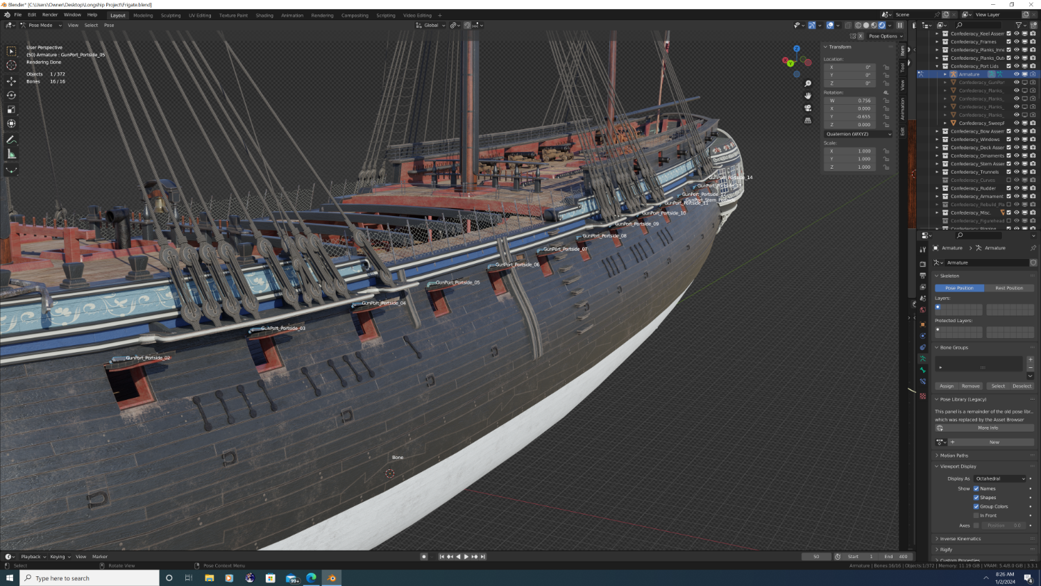
Yes Sir, you got it. I started an armature on the ship a while ago, but presently, it only applies to the gunports. The end goal will be to allow any part of the ship that could move in real life also move in the model... including, but not limited to: The steering gear [the armature will control the rudder/tiller, inverse kinematics will spin the wheel at the helm. Drivers will be used to control shape keys on the curves so that the rudder chain and ropes move accordingly] Windows [slide up and down] Gunport Lids [open and shut independently] Sweep Port Lids [open and shut independently] Belfry [swings around the block] Capstan [rotates on z axis] Doors [open and shut independently] Battery [the cannons will be able to move and fire, though still gotta figure out to what extent is reasonable]
- 105 replies
-
- 4
-
-
- Frigate
- Confederacy
- (and 1 more)
-
Indeed. And I 100% agree. I actually intend to go so far as to model the clip to which each individual removable partition was secured to the beam above and the raised foot board below. I will screenshot again when finished. Best, -Nate
- 105 replies
-
- 1
-
-
- Frigate
- Confederacy
- (and 1 more)
-
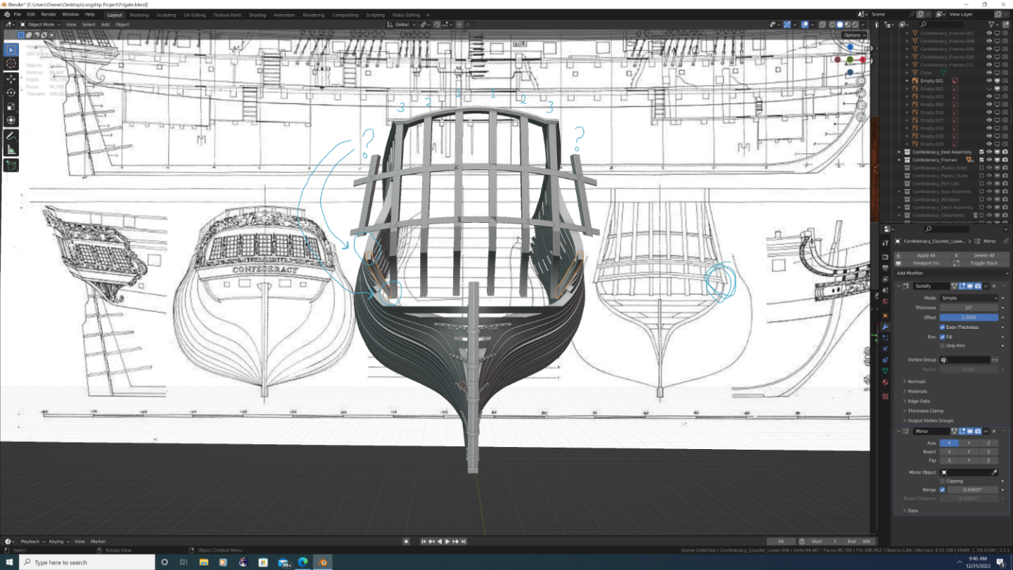
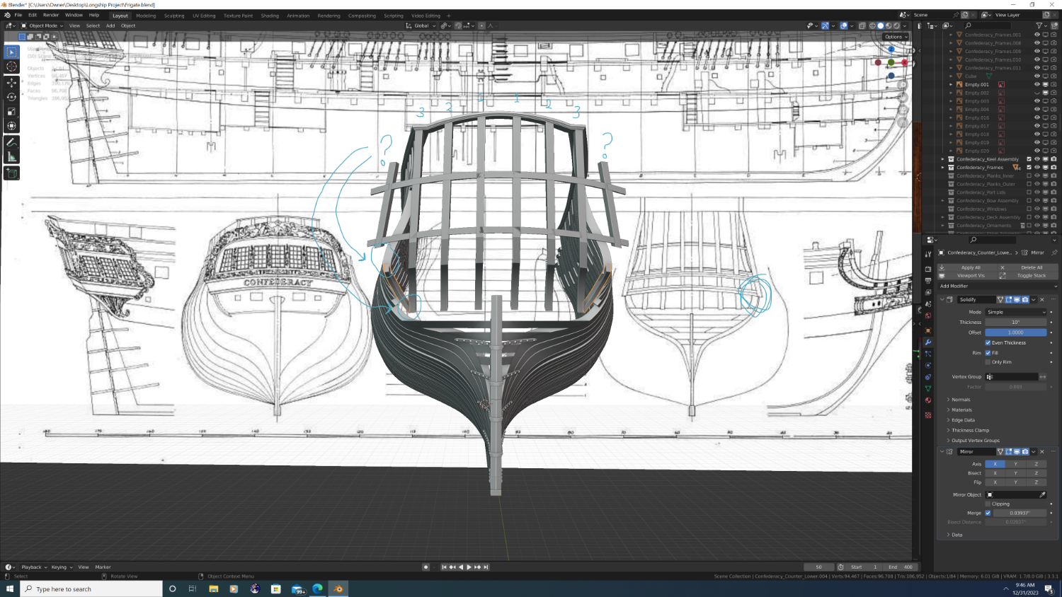
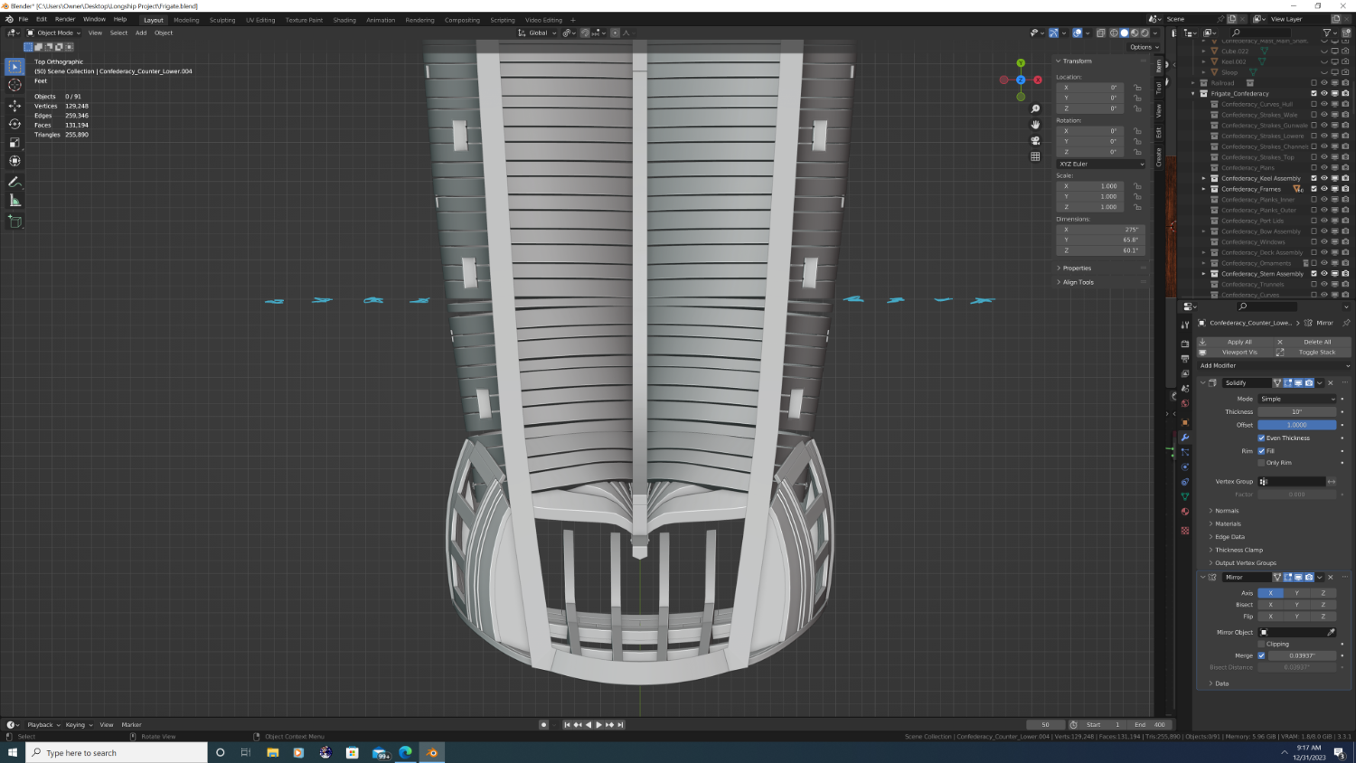
If it were any other ship, I'd agree, but I'm not sure how that would be physically possible on the Confederacy. All plans I can find show 3 pairs (6) of vertical timbers - technically comprised of the transom, counter, and quarterboard timbers) at the stern. I have all of these already but then there is an additional outboard floating timber that connects to just the quarterboard. My question is - I think there needs to be a frame that essentially sits in the corner of where the tuck meets the lower counter and possibly extends up to the edge of the outboard timber. I just now added the highlighted piece. Can you tell me if this looks correct, and if not, how I can fix it? I know that may be asking a lot, so thanks in advance.
- 105 replies
-
- 2
-
-
- Frigate
- Confederacy
- (and 1 more)
-
Indeed. I have modelled cant frames on the aft, it was just a bit hard to see on the last screenshot. All frames behind the dashed line are cant frames.

- 105 replies
-
- 1
-
-
- Frigate
- Confederacy
- (and 1 more)
-
I'd also like to correct the framing at the stern. I've deliberately held off on the wing transom until I fix the highlighted portion, but I'm at a loss on what the missing piece looks like... If anyone can help, I'd be greatly obliged. Thx!
-
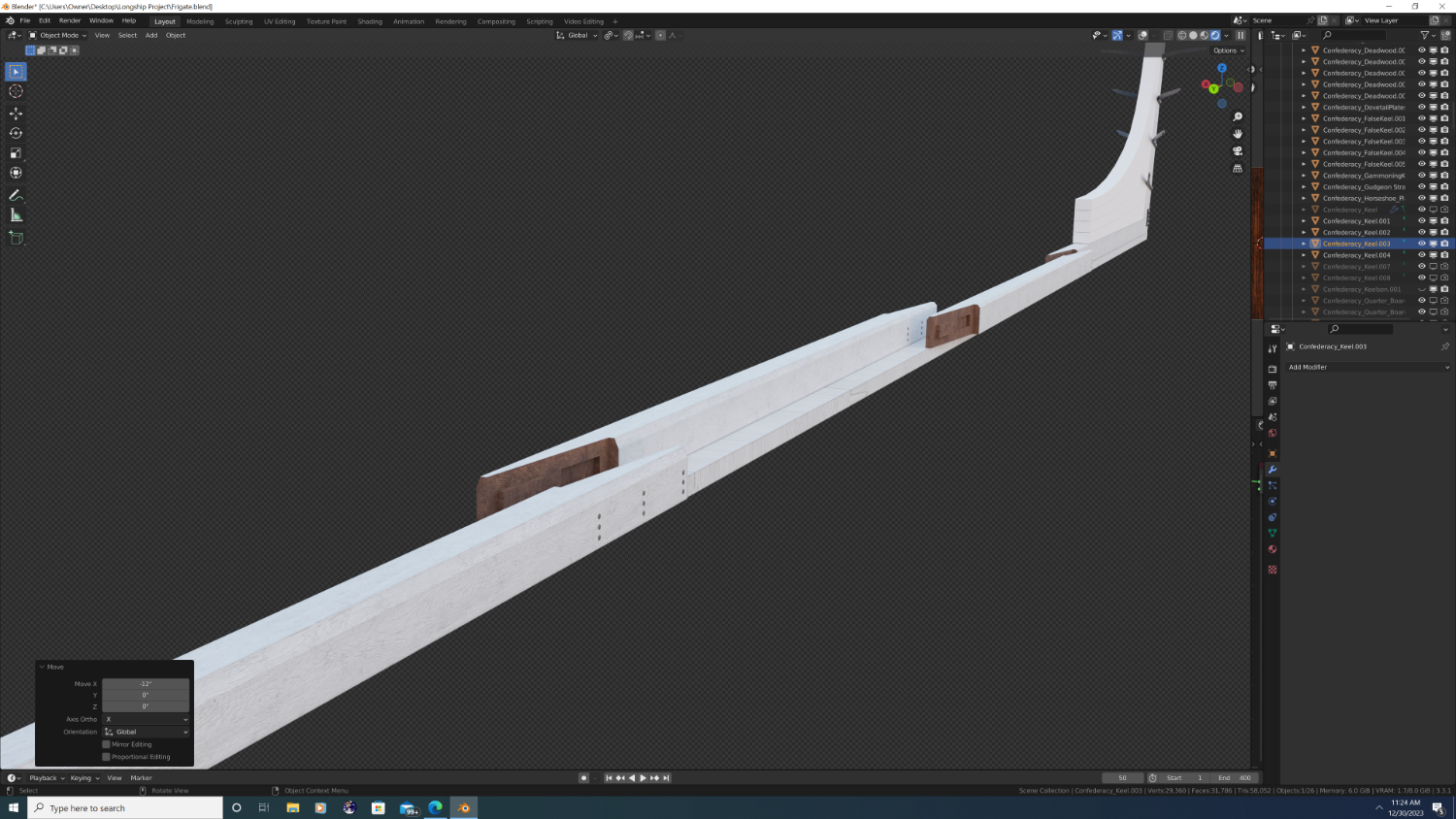
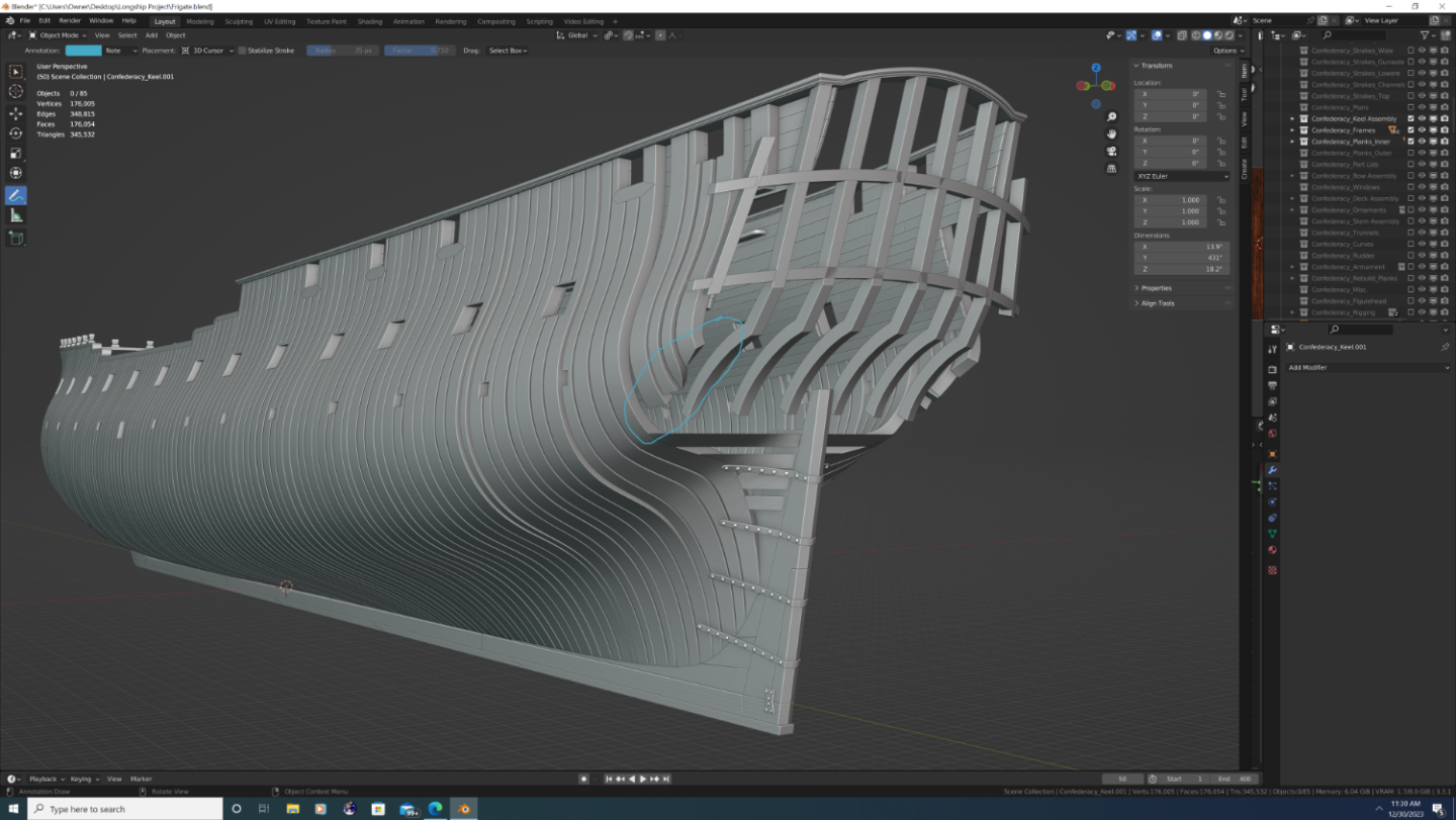
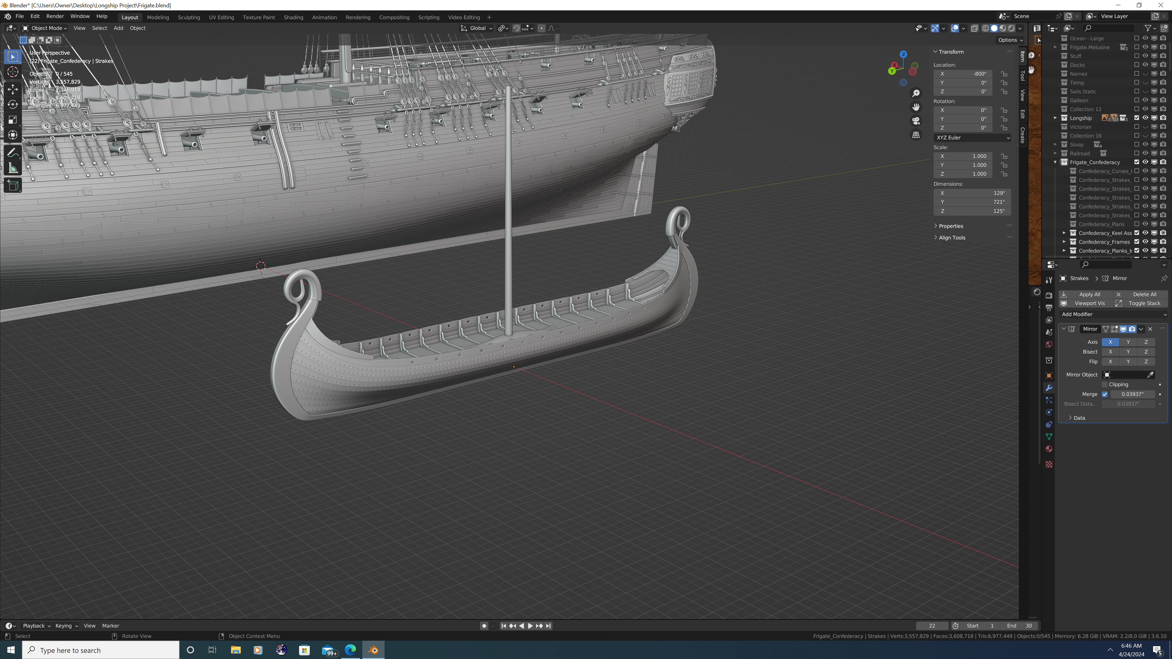
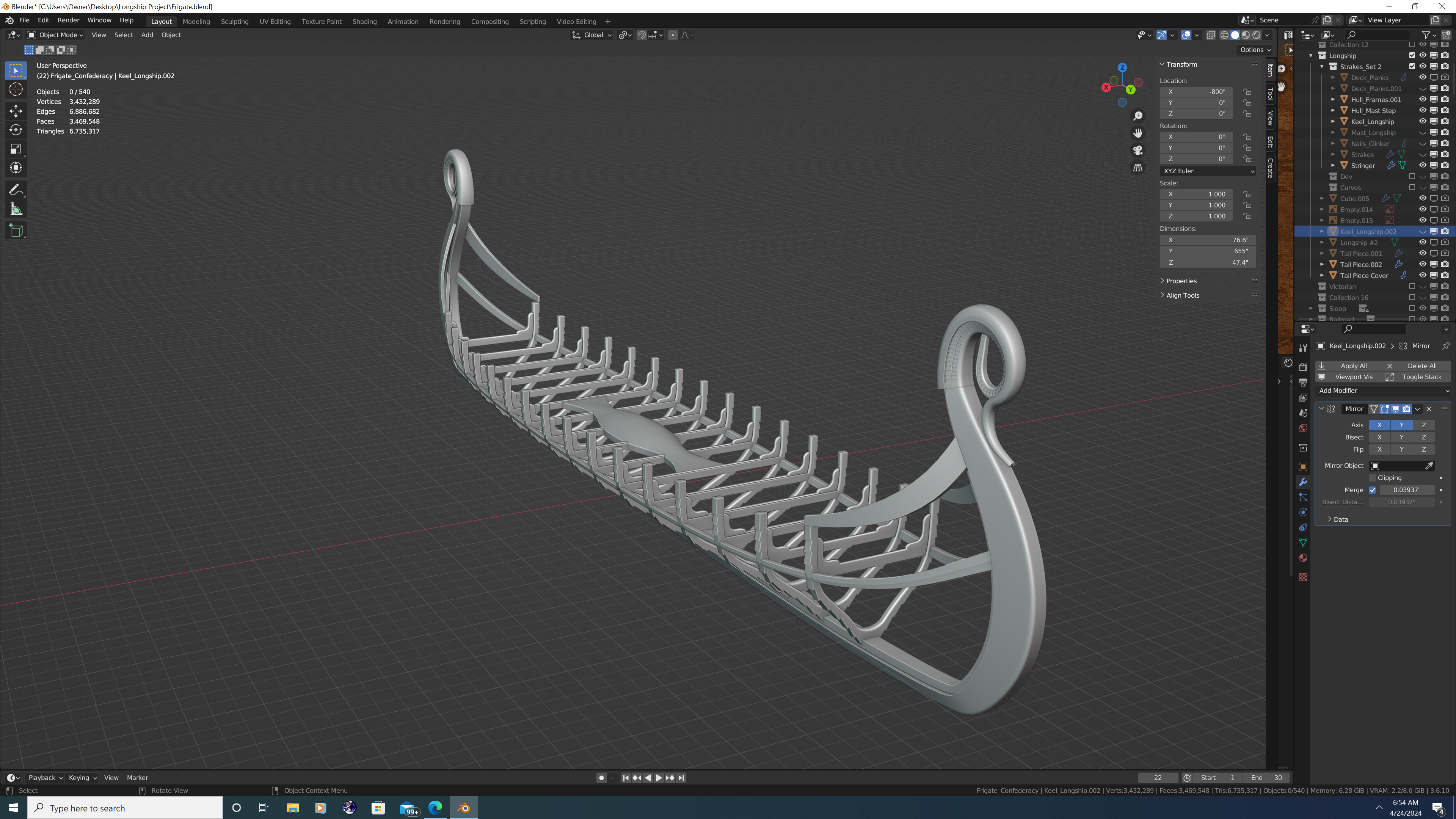
A few, seemingly random updates, but here we go: 1. Working on the partitions on the gun deck. I have all but the doors modelled, I'm now working on the faux gilding (yellow paint), at which point I'll do the great cabin (gunna be a lot of work) 2. An exploded view of the keel, which now has the vertical scarfs modelled, including the coak and table joints. I've also added the trennels on the outsides, but I'll still need to do the staples that connect the keel to the false keel.
.thumb.png.e41b094cb792c9627aaf3afe6961723a.png)

- 105 replies
-
- 2
-
-
-
- Frigate
- Confederacy
- (and 1 more)
-
So apparently, I'm the guy who models each individual clove hitch on the ratlines... because, you know, the project wasn't tedious enough already.

- 105 replies
-
- 4
-
-

-
- Frigate
- Confederacy
- (and 1 more)
-
Cloth distance from object
3DShipWright replied to Srenner's topic in CAD and 3D Modelling/Drafting Plans with Software
You should be looking for the 'Distance' field setting. It is found on the cloth object, not the collision object, beneath the 'Cache' settings. Also ensure the self-collision is disabled, or if not, that the distance setting on self-collisions is set to a value less that the object collisions. Best, -Nate.png.eb87a64611e9096706821047e99eb4ff.png)
-
Cool stuff! I especially like the details of the relief carvings on the back. I was also thinking: The lighting trick you used on the cannons (fresnel) could also be used elsewhere to simulate depth. For instance, you could use a two-tone yellow on the reliefs and counter rails, a white diagonal streak on the windows to simulate glare, etc. I can't say for certain it would come out, but just curious if you've tried anything like that? Best, -Nate


.png.0fcb65d80e5614eb7f345ac9a0cac08a.png)
.png.4d6c25b9332841c195691ab7e182256a.png)

.png.a0a52b127a6290789a3634e3e4e99101.png)

.png.a5d77f57c70887317691fb7b8cf7a3eb.png)