HOLIDAY DONATION DRIVE - SUPPORT MSW - DO YOUR PART TO KEEP THIS GREAT FORUM GOING! (Only 13 donations so far - C'mon guys!)
×


3DShipWright
-
Posts
247 -
Joined
-
Last visited
Content Type
Profiles
Forums
Gallery
Events
Everything posted by 3DShipWright
-
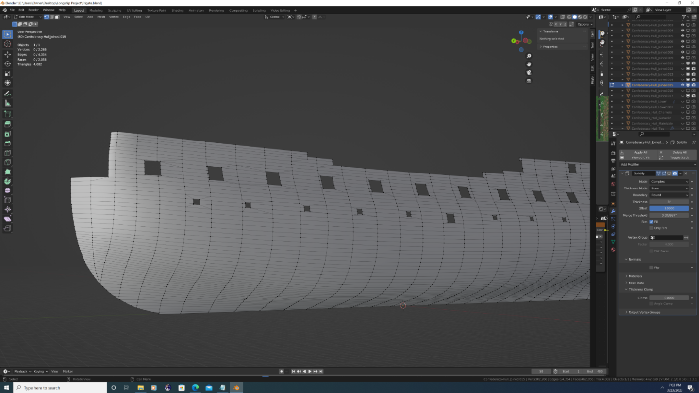
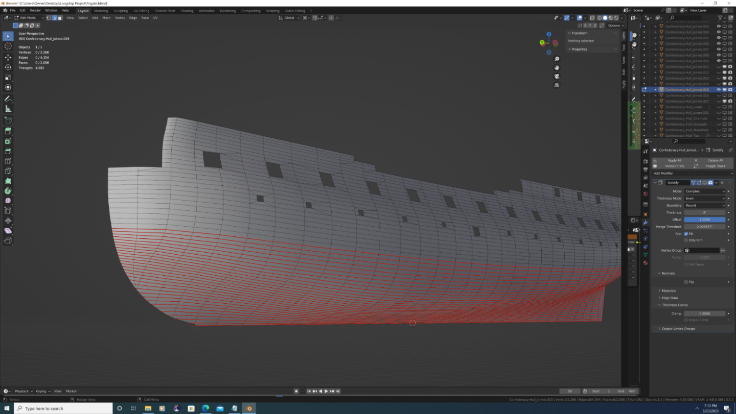
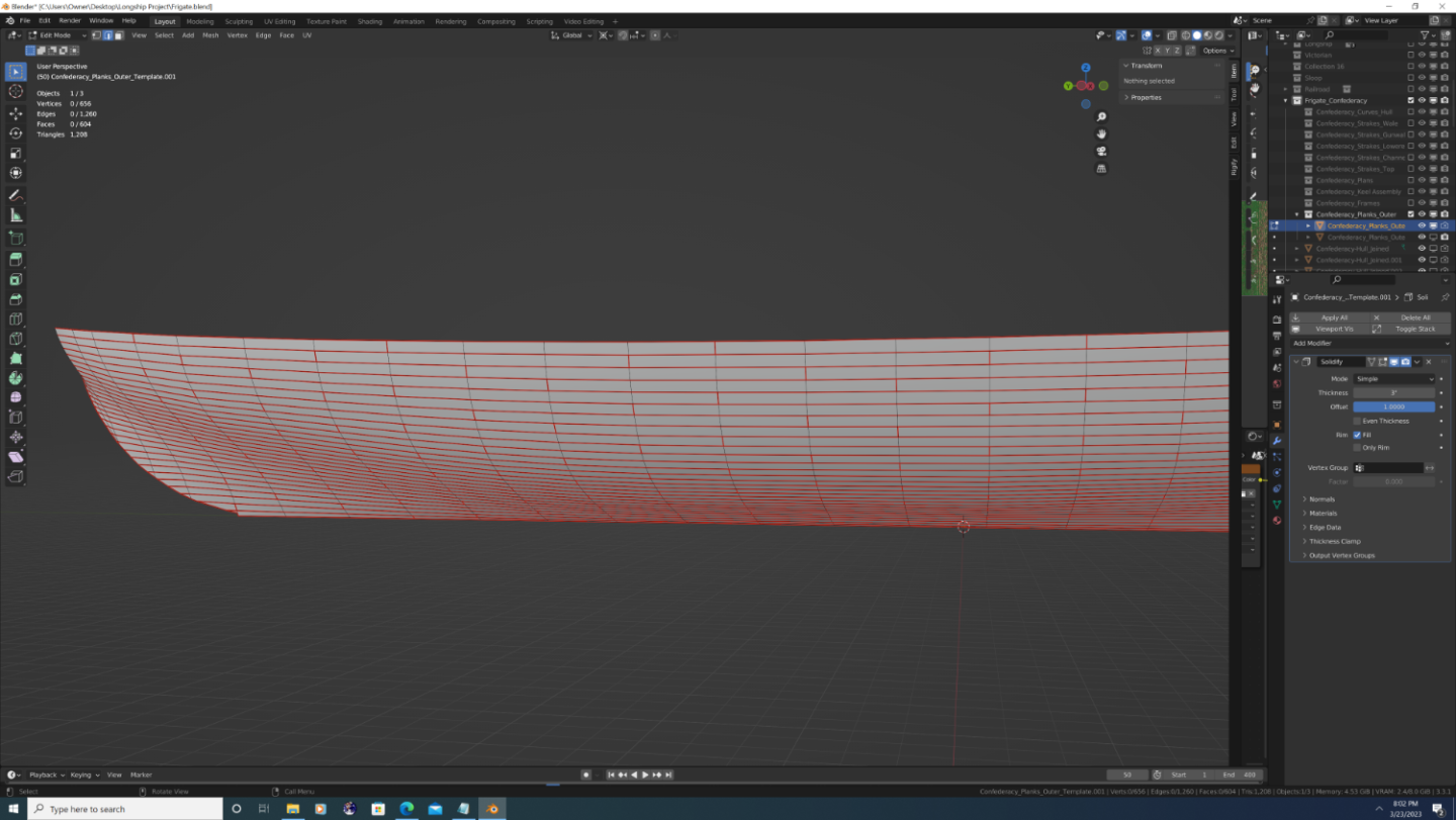
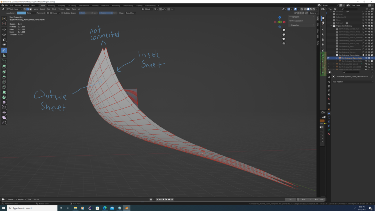
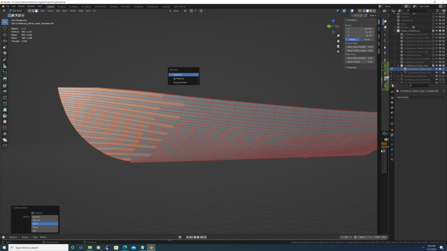
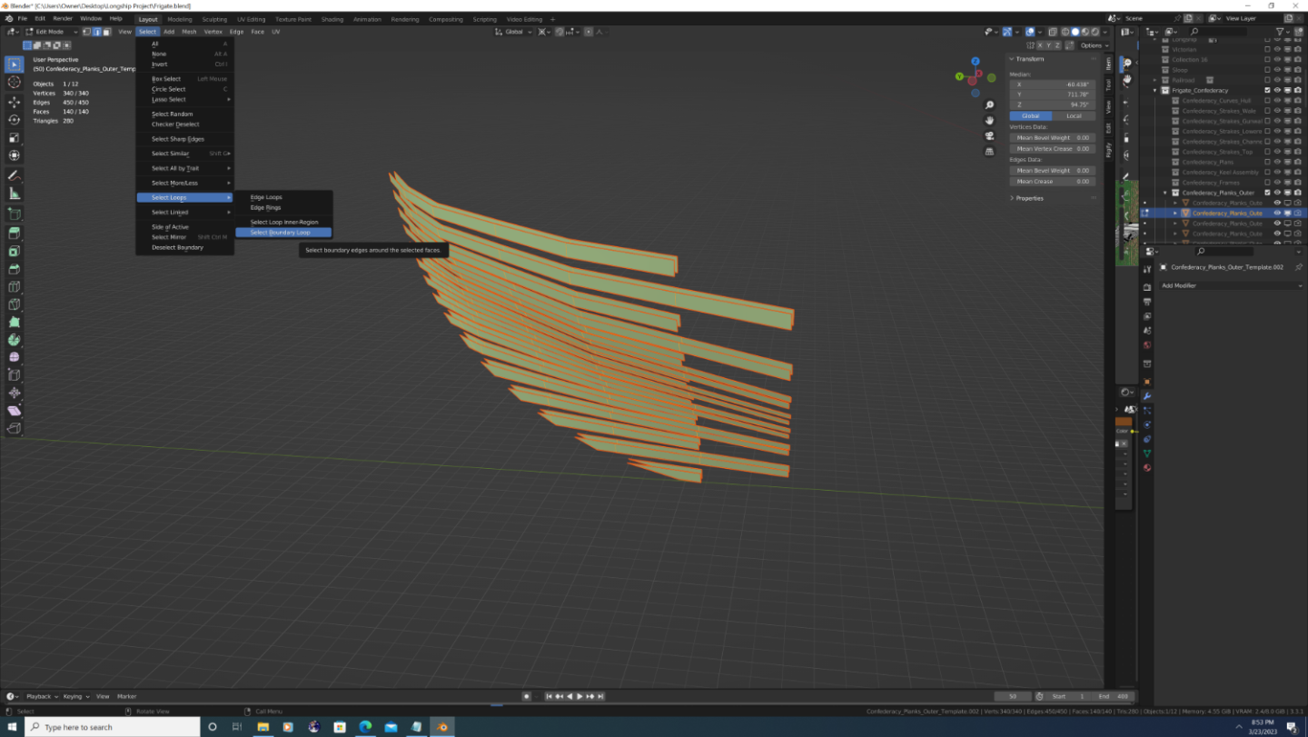
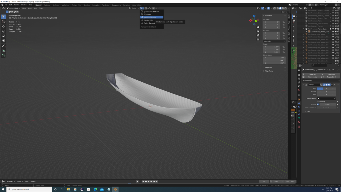
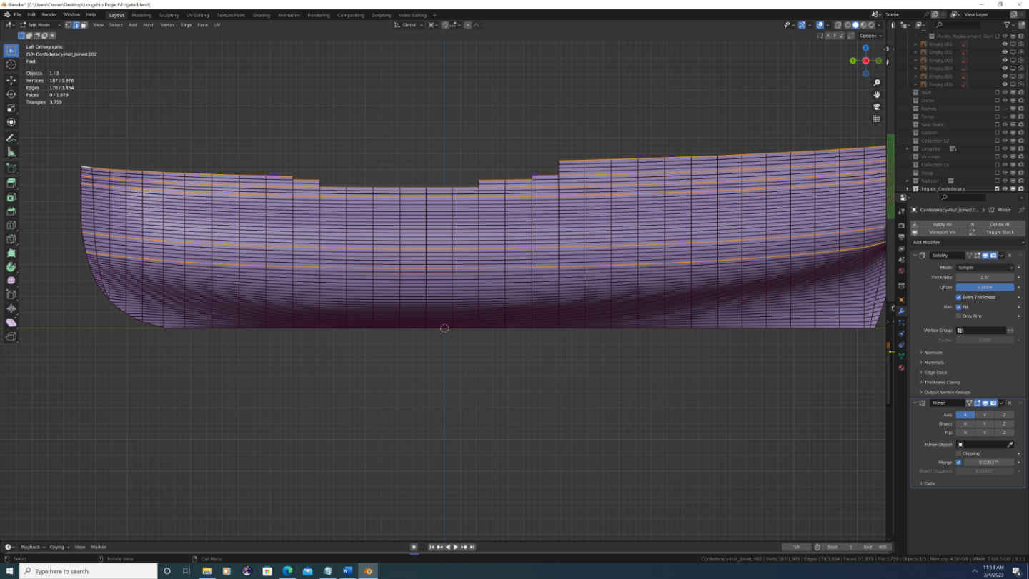
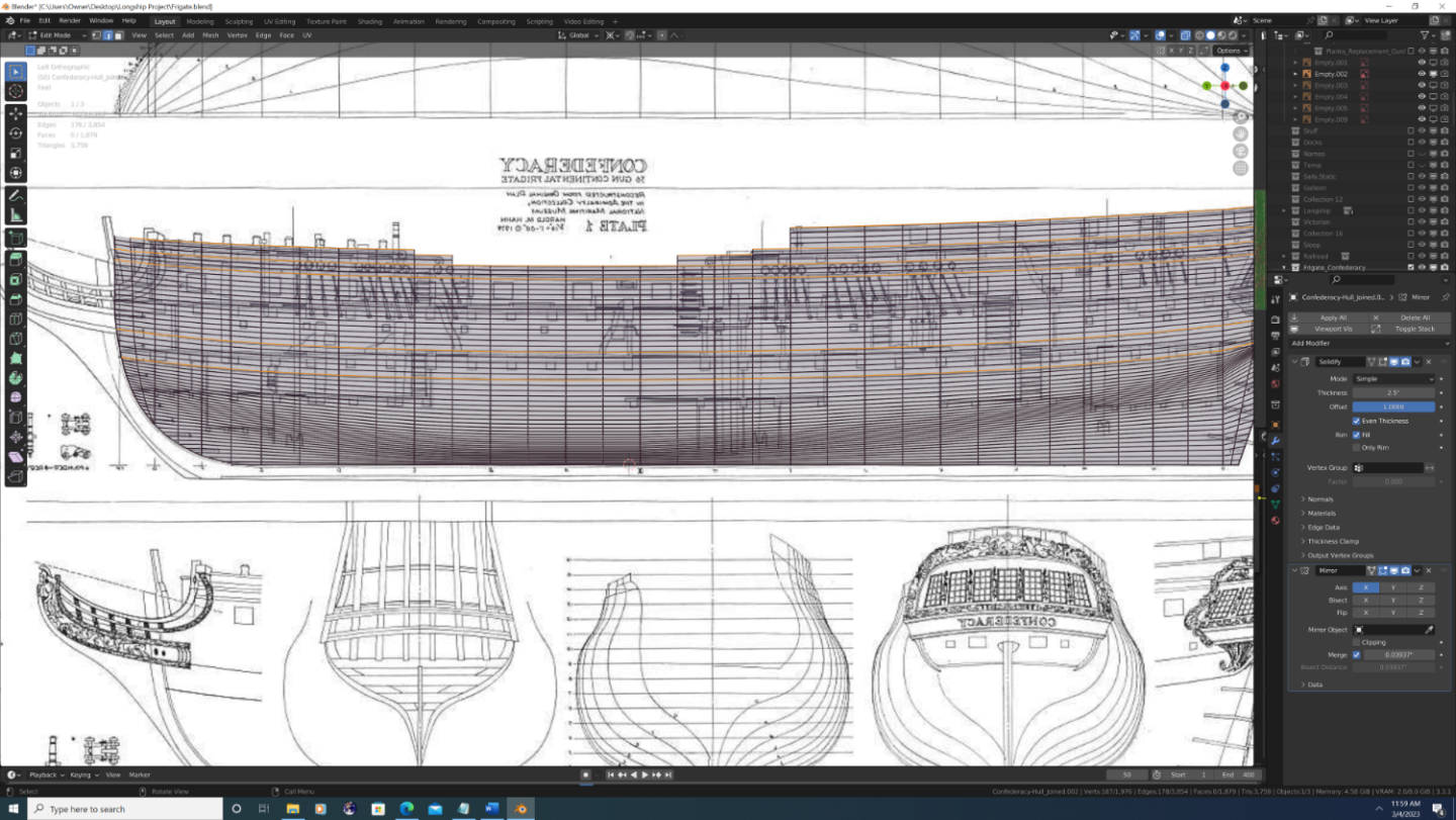
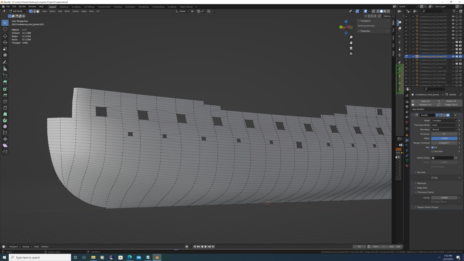
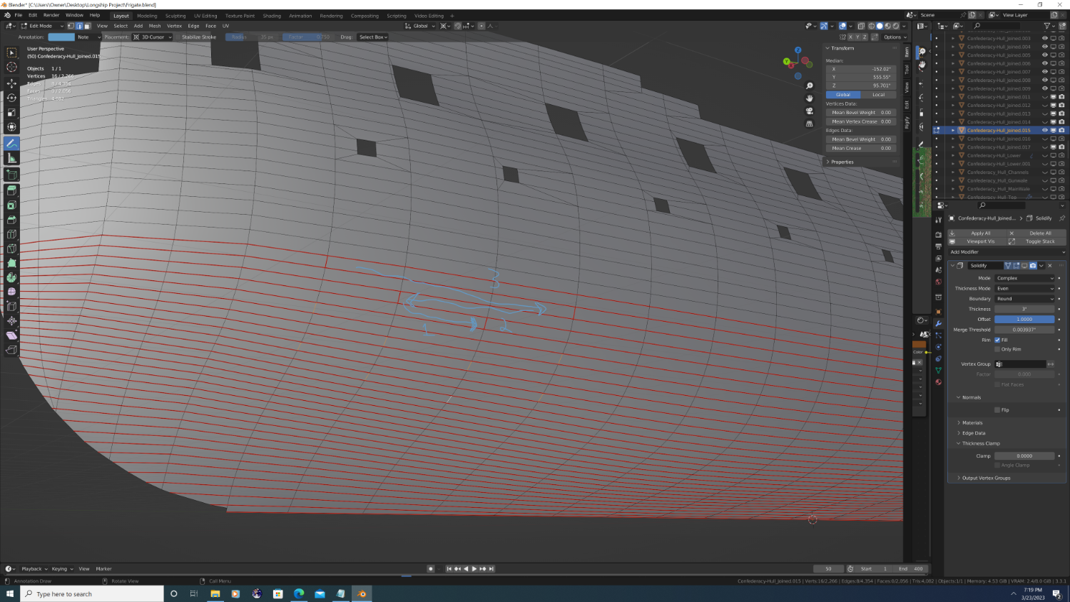
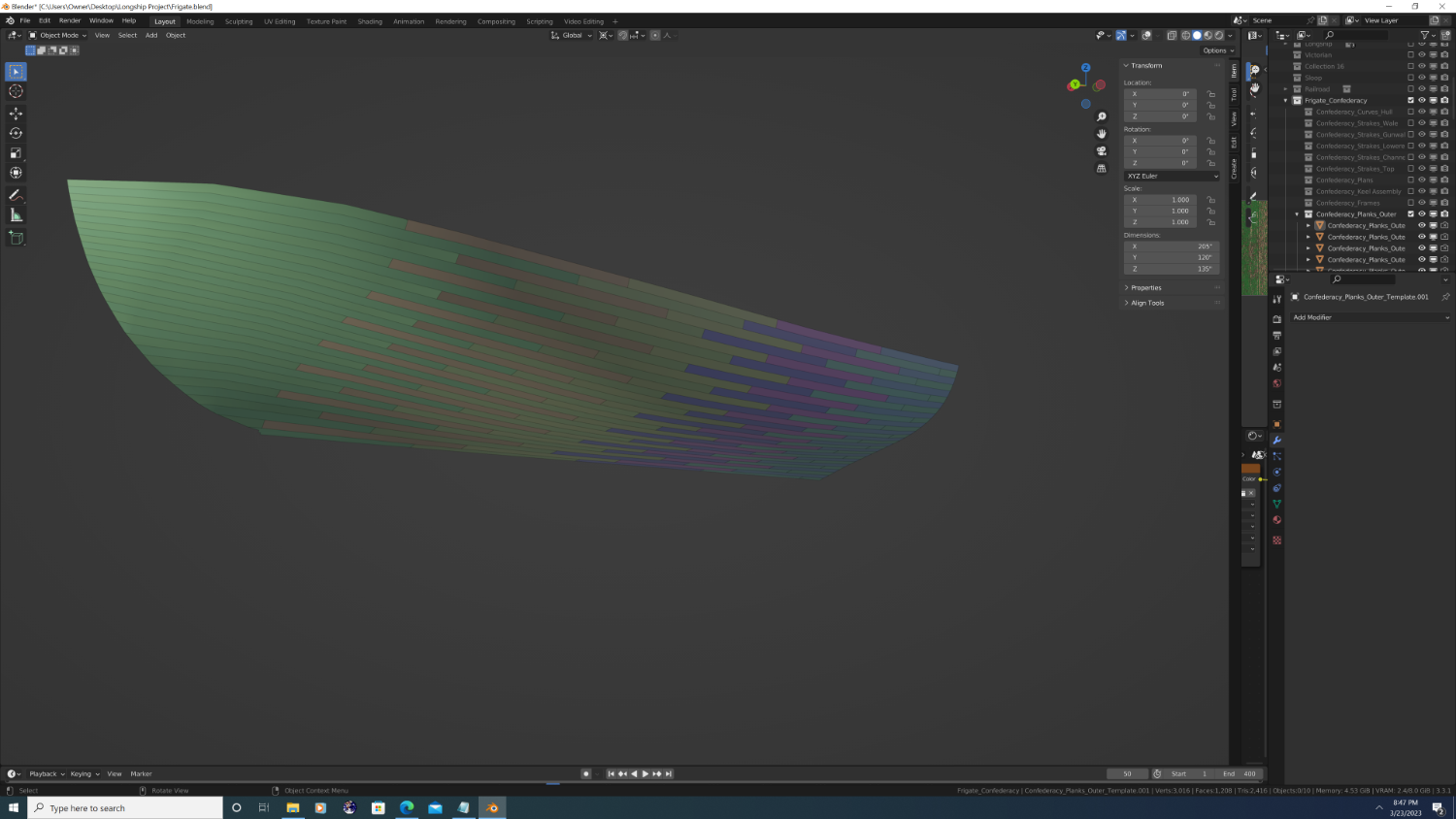
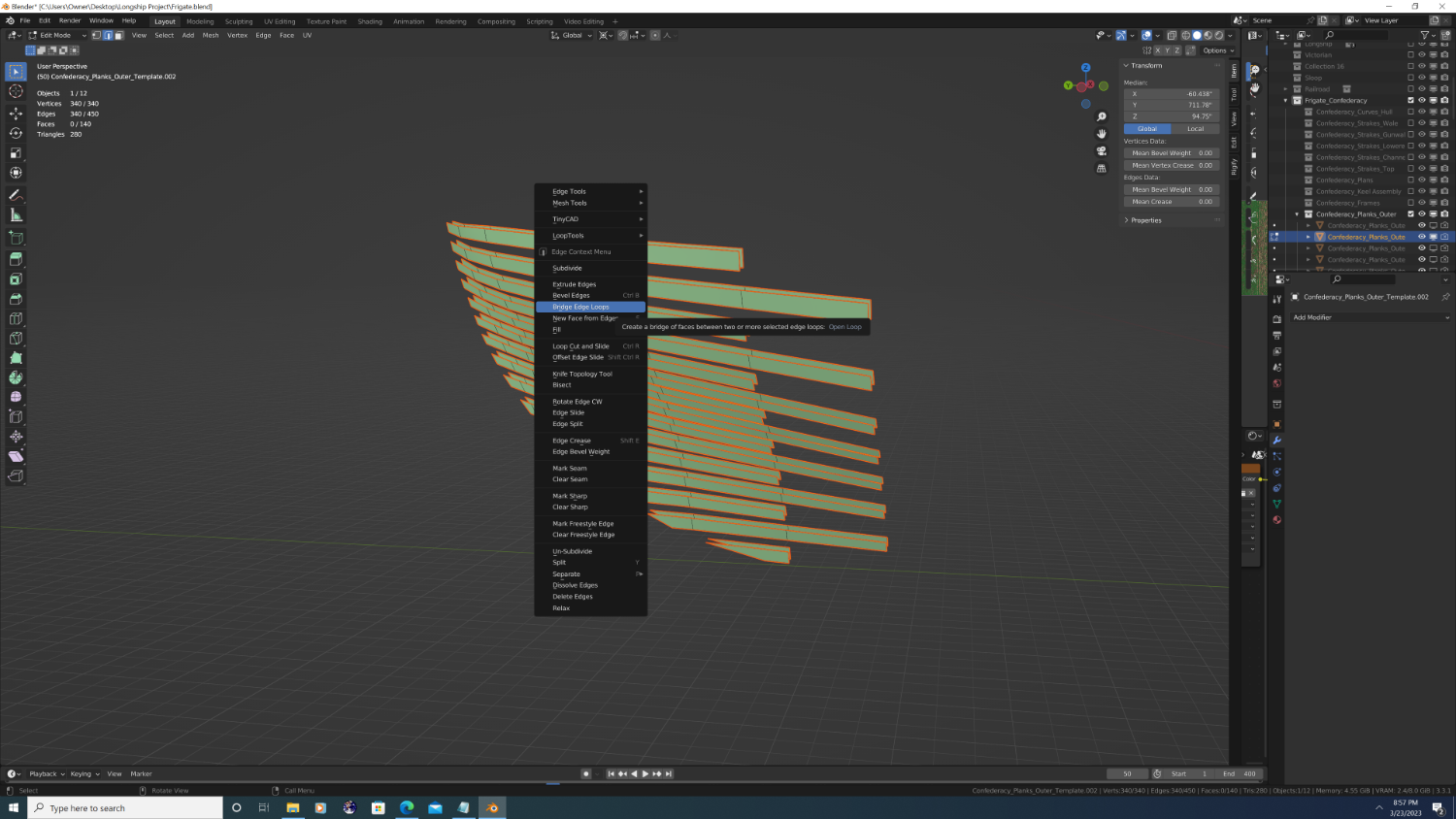
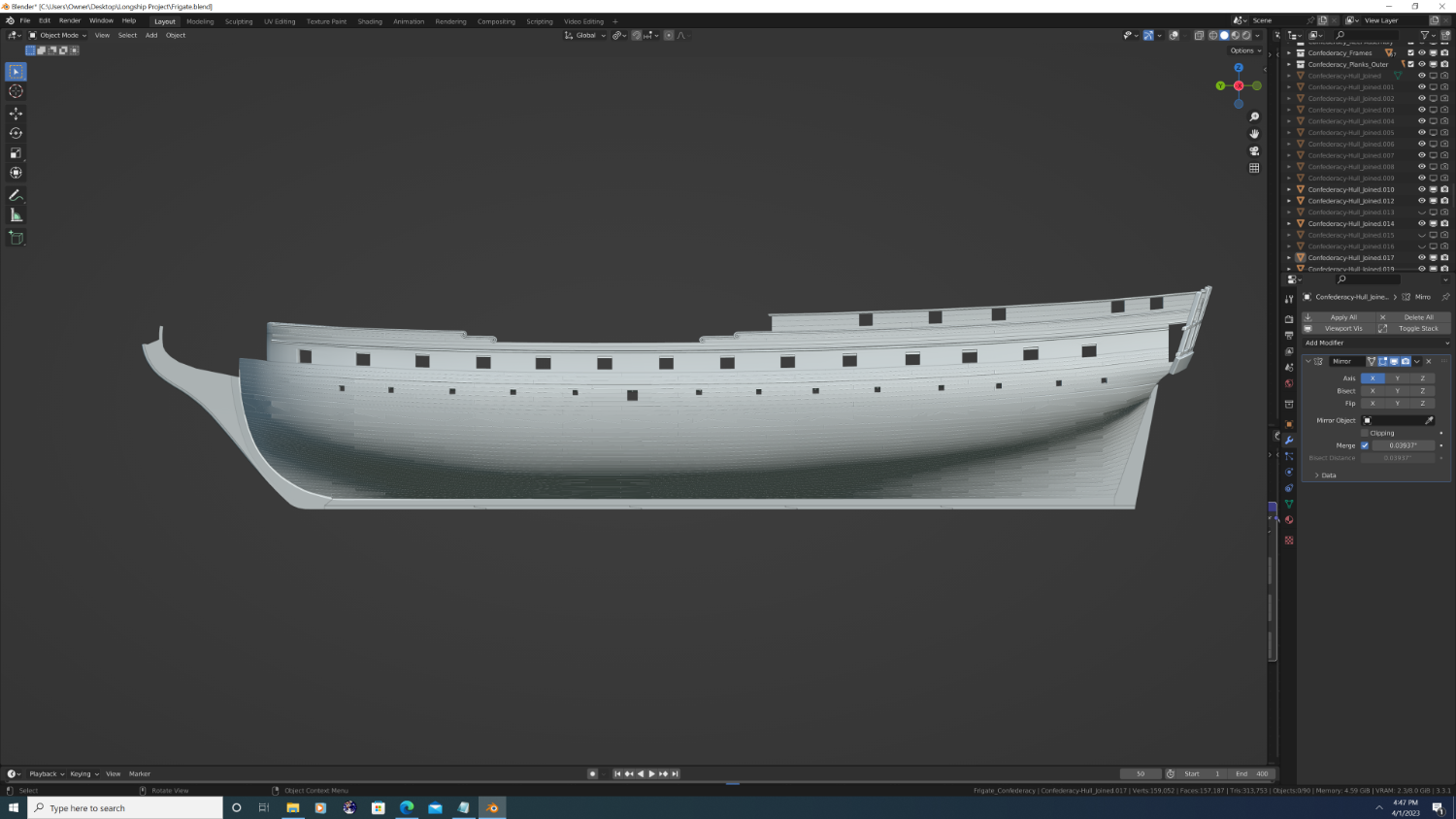
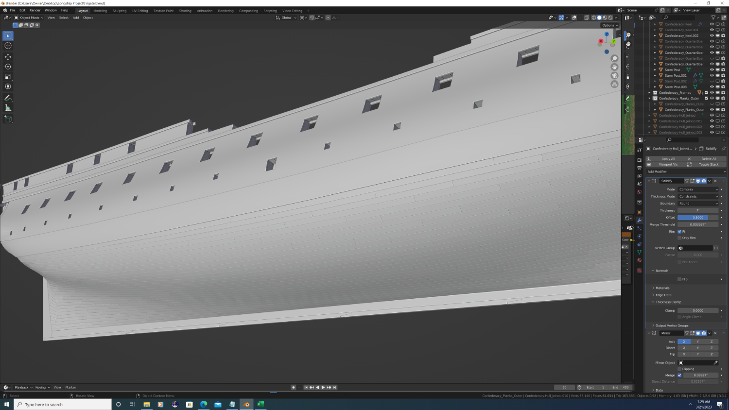
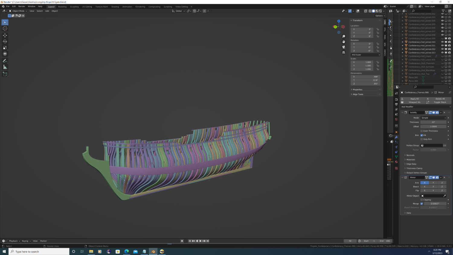
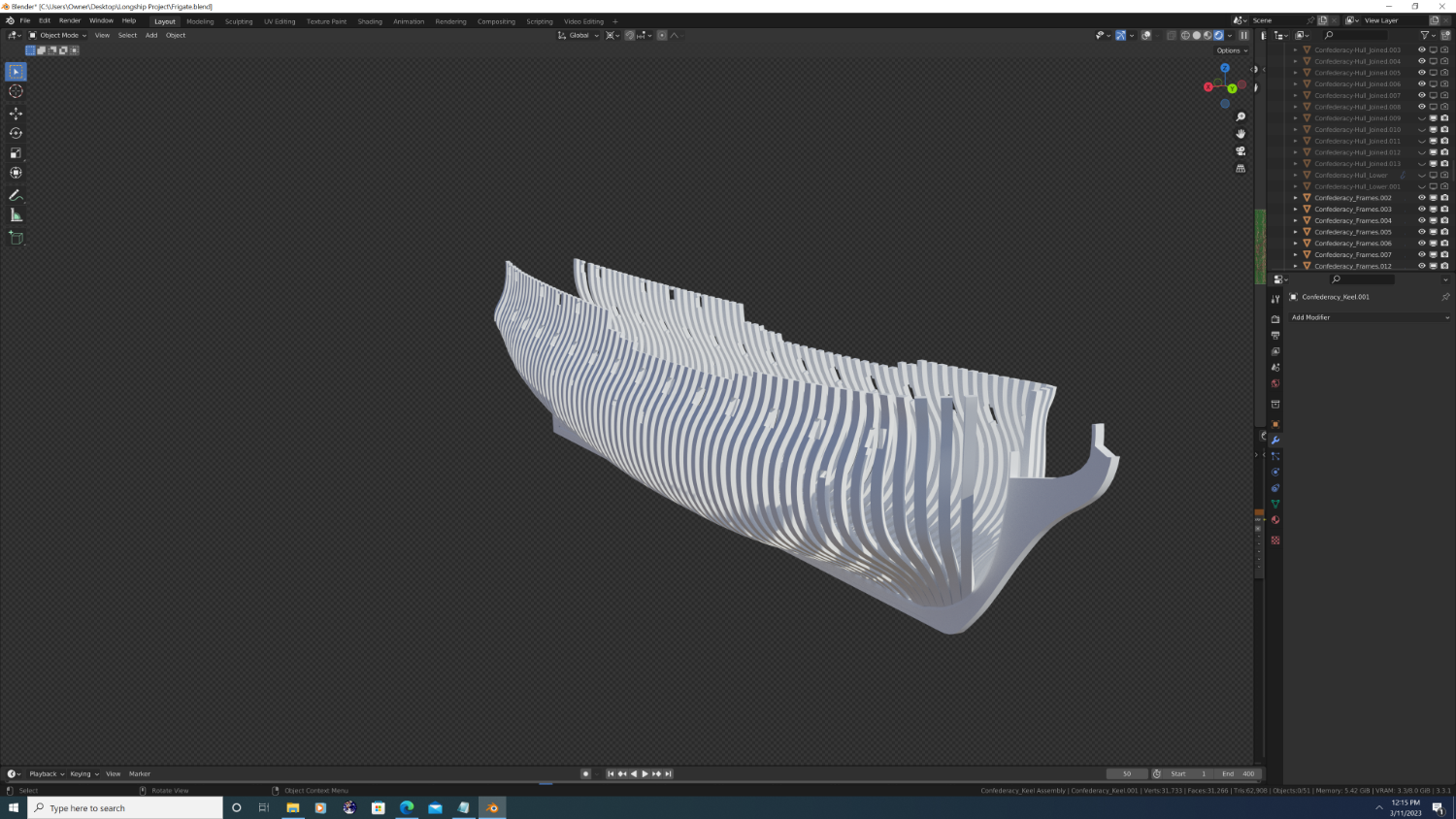
@Martes - Hey Martes, So I don't know whether to call it procedural or manual, but here is how I'm doing hull planking on Confederacy: 1. The underlying topology of the ship has to represent the outer planking to begin with. Refer to the steps at the beginning of this topic for instructions on how I got the underlying topology to match the planks if you're curious. 2. In edit mode use 'mark seams' to visually outline the strakes, then the shape of each plank on the 2D mesh. Edge loop select makes this faster than you might think, I did the whole ship in under 15 mins NOTE: I'm only showing the bottom of the hull for tutorial purposes, but the rest of the planking works the same way. 3. Use the solidify modifier to add thickness as desired, HOWEVER, DO NOT FILL THE RIM. Apply the modifier to get two separate 'sheets'. 4. In face select edit mode, press 'L' to highlight the front and backs of each plank and separate them using 'P'. You can do this in groups of planks as long as they're not touching 5. Go to each separate plank set object, edge select in edit mode, and choose select boundary loops. 6. Then you can bridge edge loops together, just make sure 'Loop Pairs' is selected. 7. Finally, join everything back into one object and change the 'Transform Pivot Point' to 'individual origins' Go into edit mode, select everything and press 'alt+s' then '-.1' to shrink each island along the normals by .1 inches (or whatever value looks good in metric units, just keep it small)


- 107 replies
-
- 4
-

-
- Frigate
- Confederacy
- (and 1 more)
-
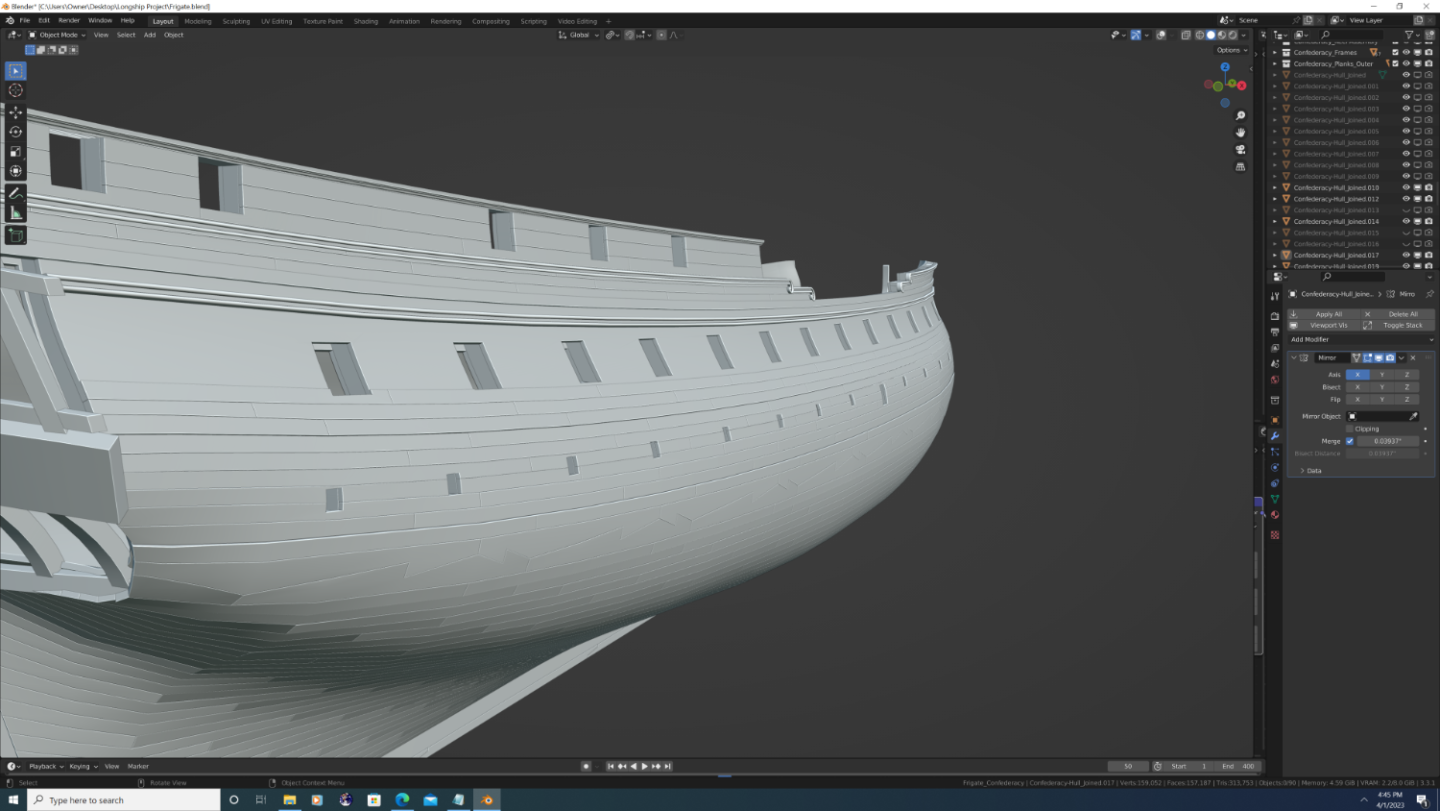
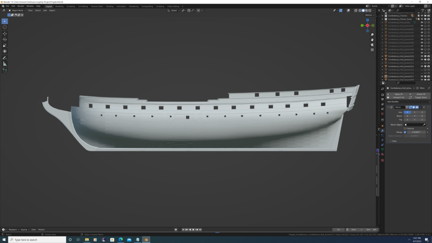
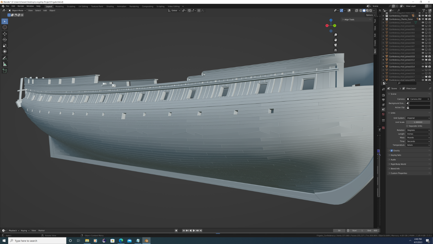
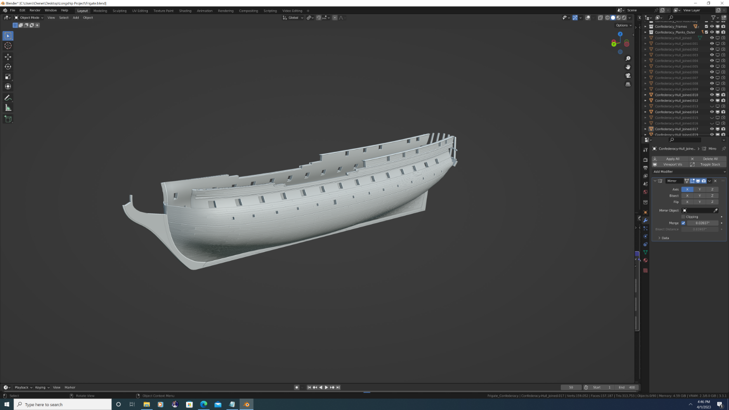
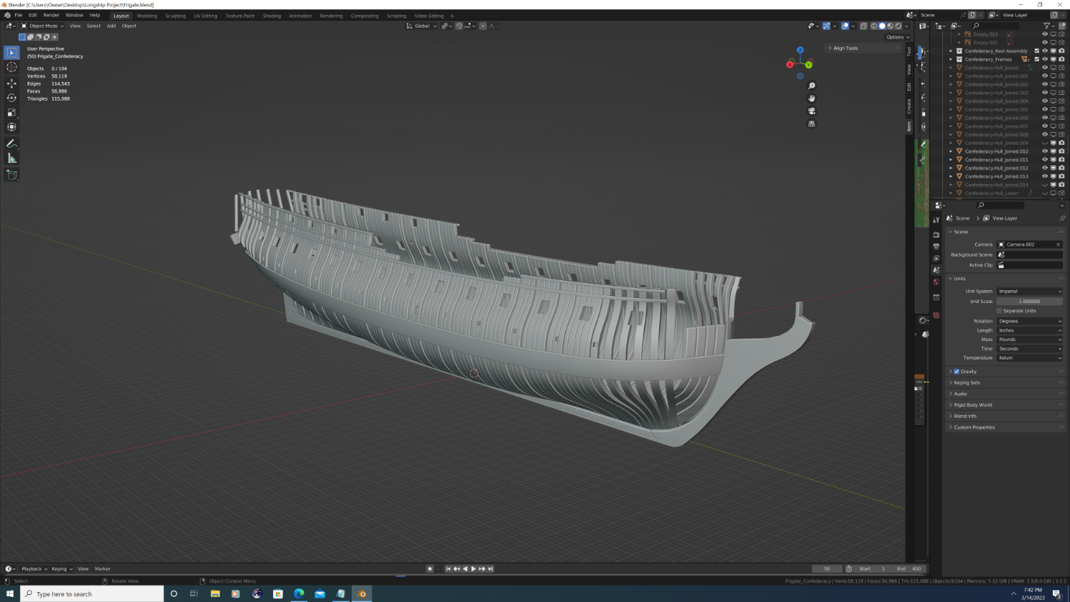
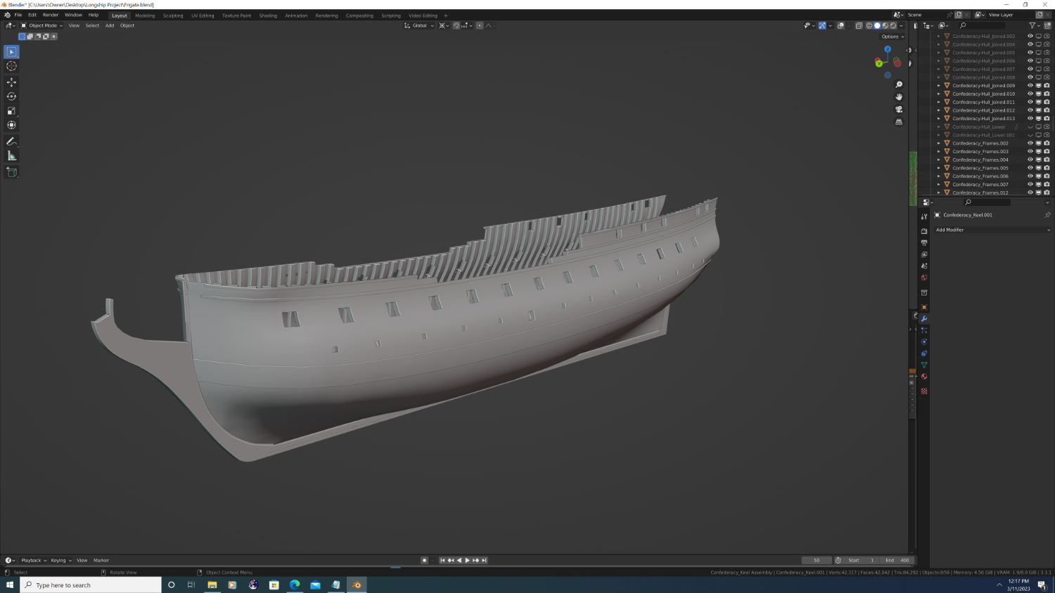
Outer planking nearly complete. Rough tree rail complete. Caprails apart from the forecastle are finished. Trim pieces nearly finished. Mouldings will be fine-detailed later to a cohesive style. For anyone interested, the planking offsets from the hull frames are as follows: Rabbet to Wale: 3in Wale stringers: 5in Wale Hook-and-Butt blocks: 4in Top of Wale to Gun Deck Clamp (inboard on the Confederacy): 3in Gun/Channel Plate/Scuppers Wale: 4in Planking above Gun/Channel Plate/Scuppers Wale: 3in Channel Stringer: 5in Quarter Deck Stringer & Forecastle Stringer 5in Trim Pieces: +2in, maximum from surface of their respective perch Rough Tree Rail: 15in maximum


- 107 replies
-
- 4
-
-
- Frigate
- Confederacy
- (and 1 more)
-
Yup - I'd echo what @Waldemar said. Well done indeed.
-
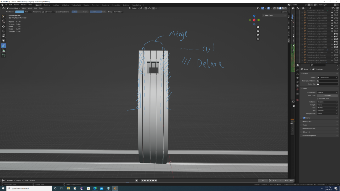
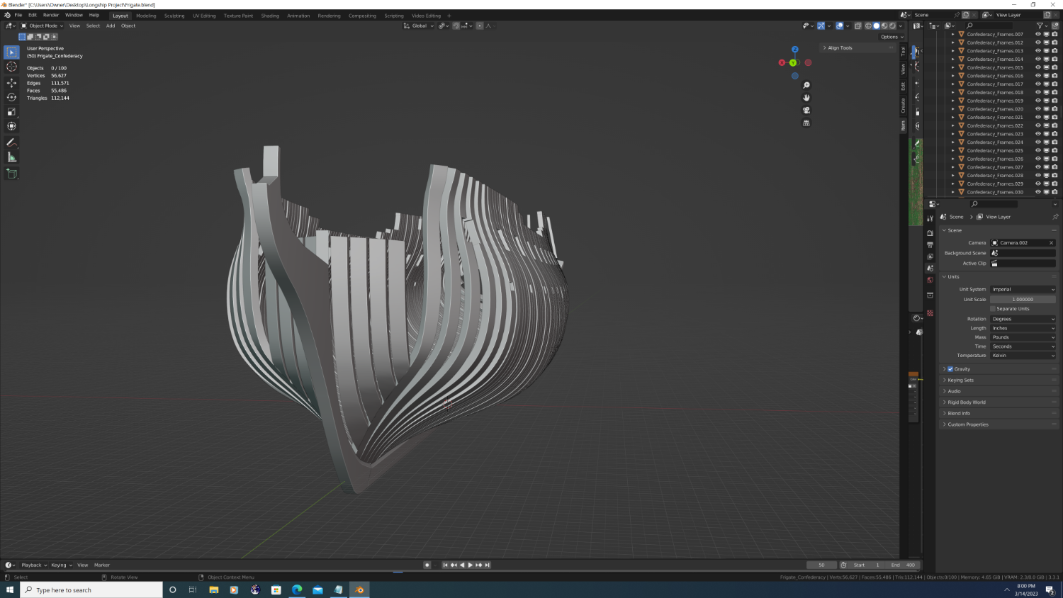
I'm trying out a new method of planking for the Confederacy, and gotta say - so far it's working out rather well. No overlapping geometry and equal gaps between the boards regardless of the twist of the hull...

- 107 replies
-
- 4
-
-
- Frigate
- Confederacy
- (and 1 more)
-
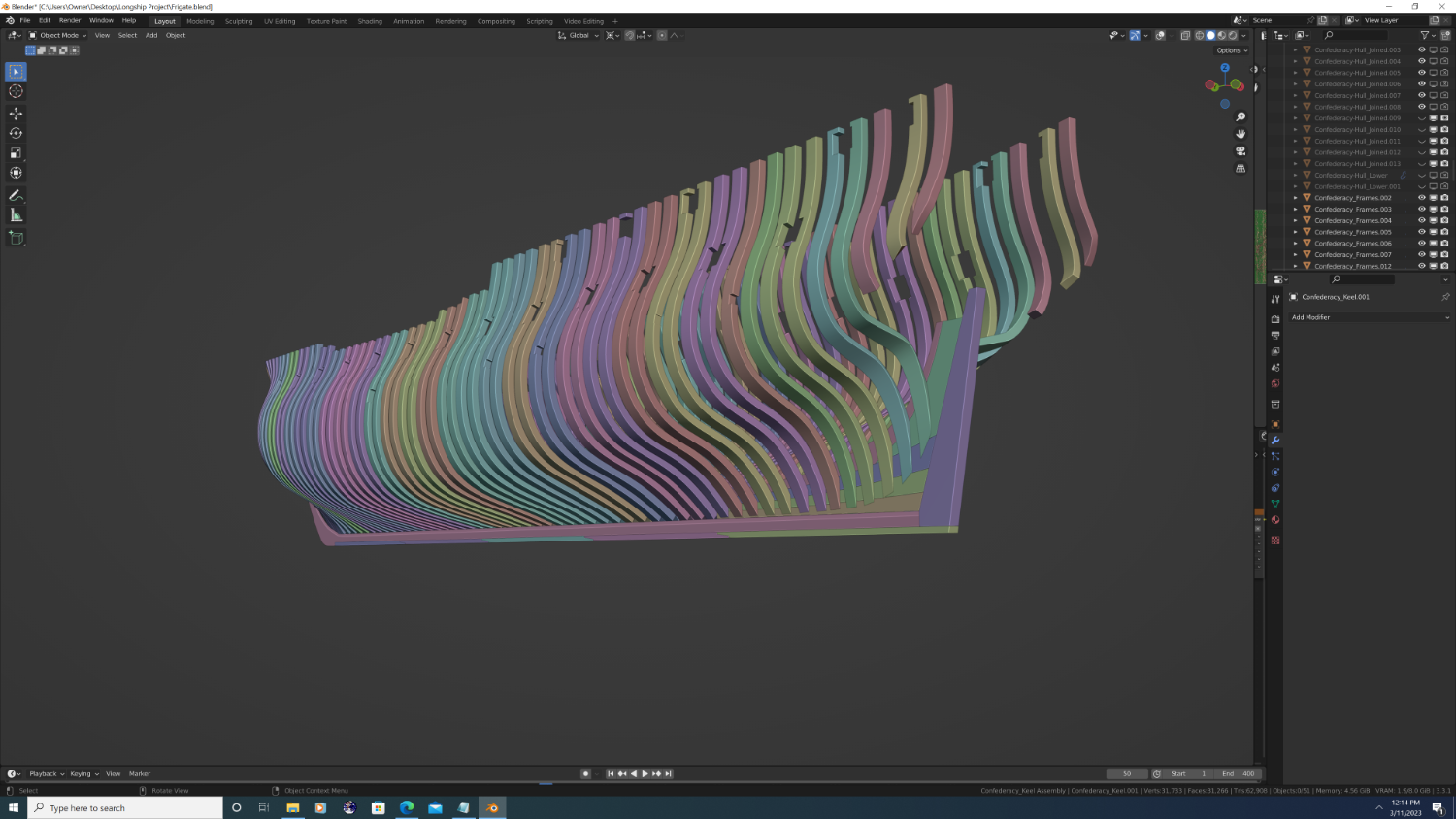
@Martes Yep, good call and that's precisely what I'm doing now. I've added all filler frames aft of the bow cant frames and before the stern cant frames. I actually added narrow filler frames to sandwich in each pair of double around the ports. I'll end up joining these 'narrow' filler pieces with their neighbors and resplicing them to create the true doubles look, but even now the ratio and overall frame plan feels way better than it did before. Finally, I've added the hawse pieces and cut them short to accommodate the bow deck (name?). I'm keeping the cant frames from the 45-90 degree radials, but I will thicken and nudge them back on one another to form a more authentic shape and close in some gap space.


- 107 replies
-
- 3
-
-
- Frigate
- Confederacy
- (and 1 more)
-
This is some good work! Given your extensive knowledge of frigates in particular, I was starting to wonder if you'd ever attempted a high poly model. If you're taking on volunteers, I'd be honored to collaborate on texturing her with you. Just let me know
-
@Martes And yes, I agree and will put additional framing between the ones I already have
- 107 replies
-
- 1
-
-
- Frigate
- Confederacy
- (and 1 more)
-
@Martes All true, you're just jumping the gun a bit... Here, I went ahead and did a mockup of one of the frames as I want them all to look when I'm done framing.

- 107 replies
-
- 2
-
-
- Frigate
- Confederacy
- (and 1 more)
-
@Martes So that's an excellent question, and something I've been stressing over as I do this part. Short Answer: At least as far as the main framing is concerned, Yes, I'm sure. As to whether or not the plans I'm using are complete I don't know. I'll be using the Constitution and Essex to fill in any gaps in documentation, but only as little as possible. Long Answer: There was only one set of Confederacy frame plans I could find online, but there are several things about it that lead me to believe they aren't 100% accurate. However, unlike my last project I did extensive research before I started this time. So here's what I do know: The frames depicted in the picture above are completely wrong. I've seen images of that cutaway model before, it's not unique to that museum. Even in the model, those frames are fake. Inside are solid cross section frames like on the Modelship Ways kit. A true tell is the placement of the doubled frames. There were many American frigates that utilized the classic British style, but in the revolutionary time frame those that did aligned them with the gunports and in Confederacy's case, the sweep ports. This meant an uneven spread along the keel, but structurally, a more sound design. Around this time Americans introduced pieces of southern oak into ship hulls. When they did, they utilized thicker but fewer frames overall. (How Ironic that "Ol' Ironsides" was technically softer than other ships) However, there do need to be either supplemental timbes or at the very least, filler deadwood around the steps, cant frames, hawses, etc. I still have alot left to do with just the primary frames, so I'm not risking anything by pushing the in between stuff off a bit. Best, -Nate
- 107 replies
-
- 2
-
-
- Frigate
- Confederacy
- (and 1 more)
-
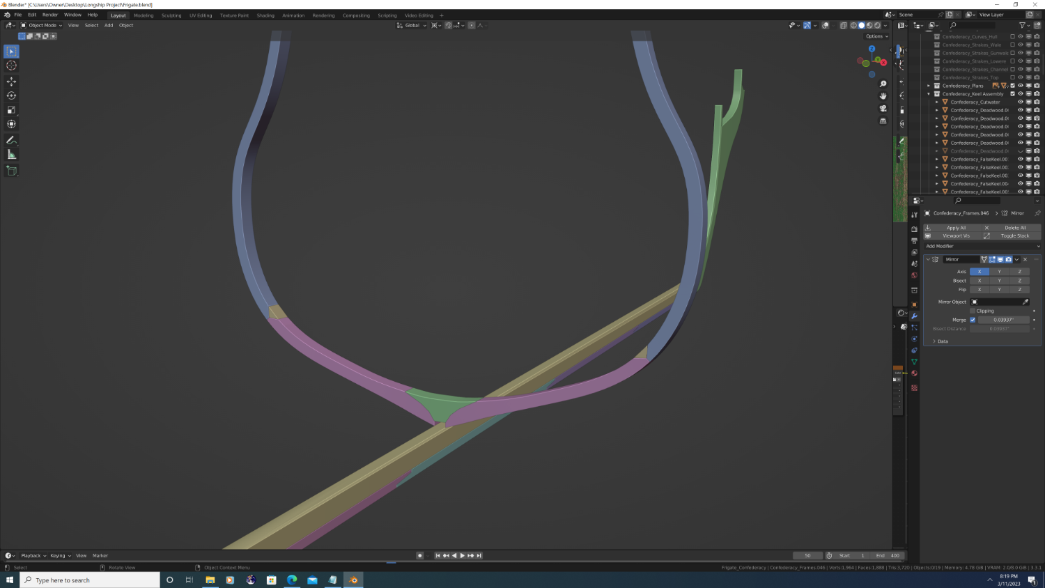
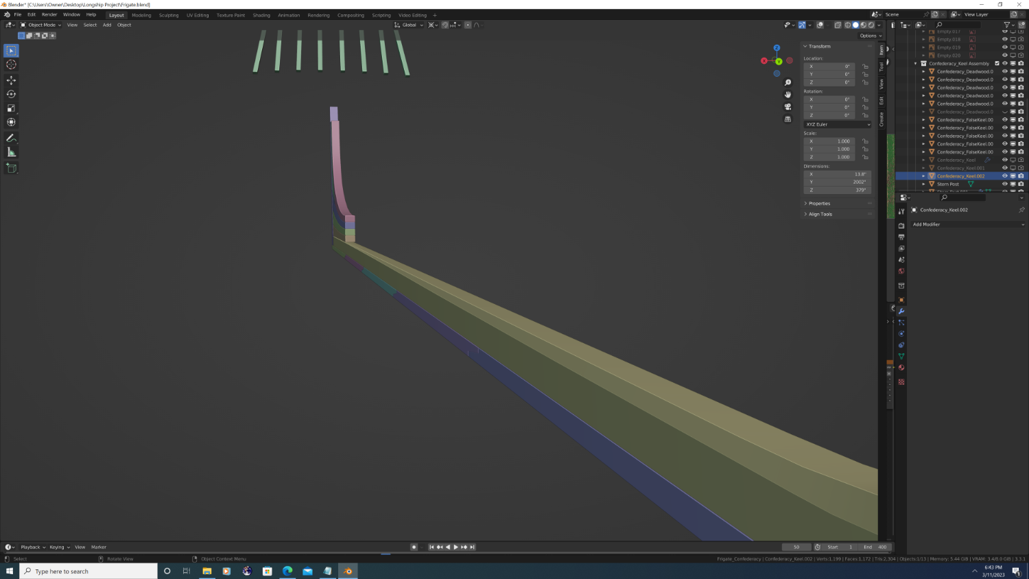
Basic Hull shape complete, starting to separate the keel 'stencil' into the various components adjoined with their correct wood joints (Nibbed scarfs, hook and butts, and rabbet joints - not to be confused with the rabbet line lol). Here a couple screenshots. From the images below, please note that I have yet to: Make the rabbet line twist correctly curve moving aft. Properly secure the main frames using the rising wood stringer and alternating sets of cross-chocks and rebates; i.e. the makeup of the keelson. Add the final cant frame or hawse pieces to the bow. Interestingly, the plans I'm following don't show Confederacy having any dedicated hawse pieces, only an additional two cant frames that continue to walk up the gripe/boxing of the stem... If you have any knowledge of this, I'd highly appreciate it


- 107 replies
-
- 5
-
-
- Frigate
- Confederacy
- (and 1 more)
-
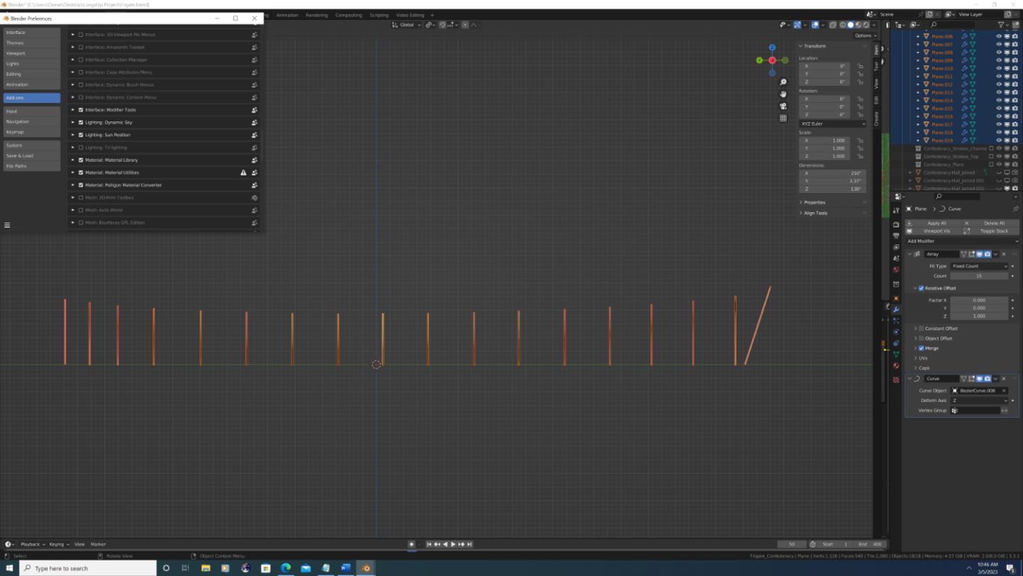
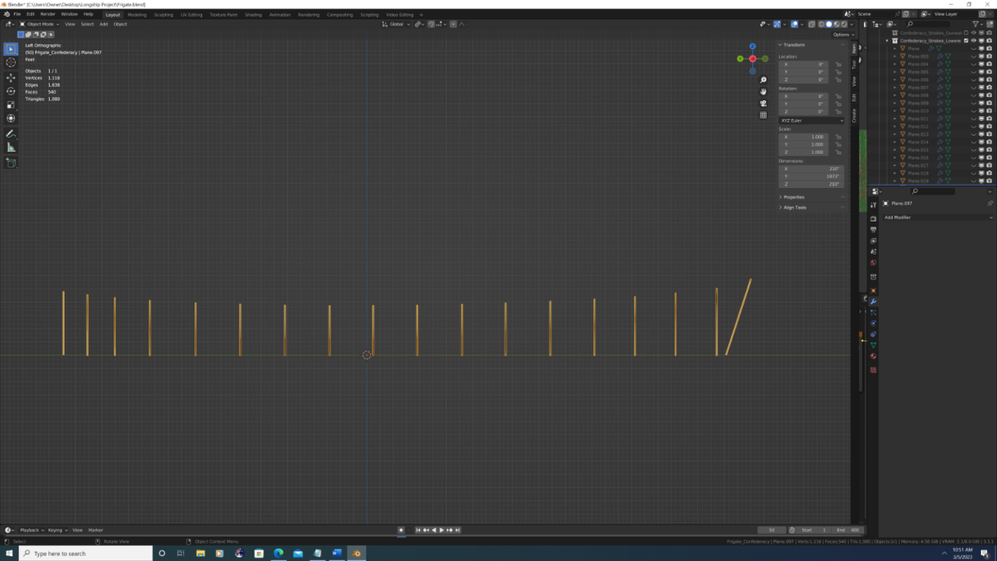
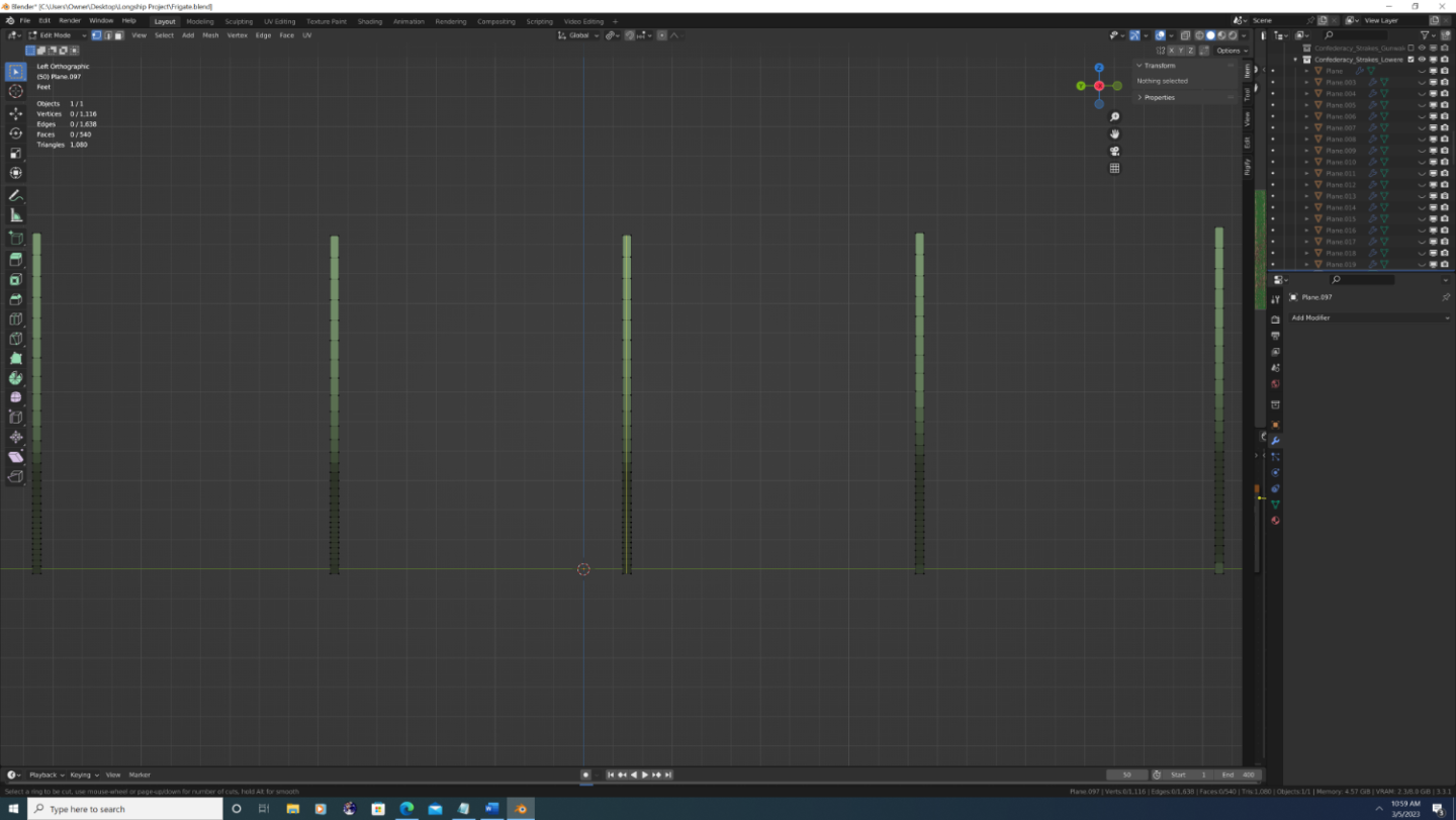
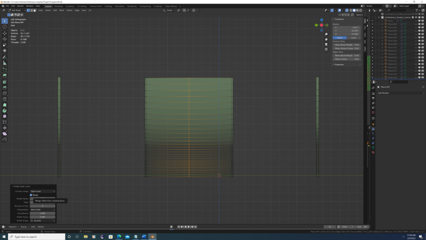
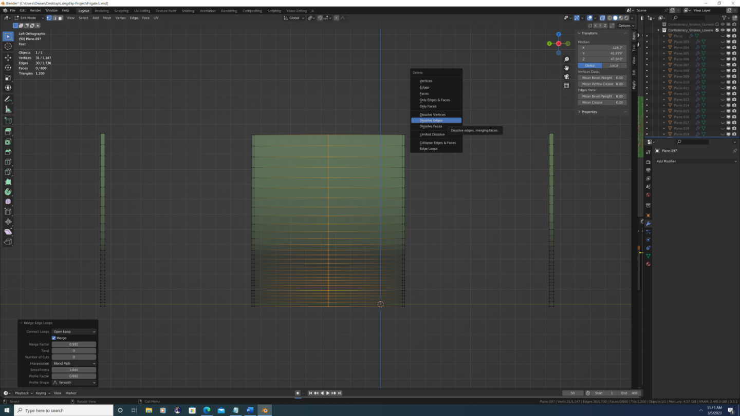
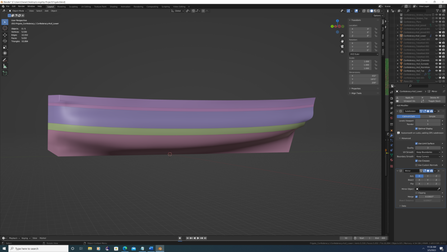
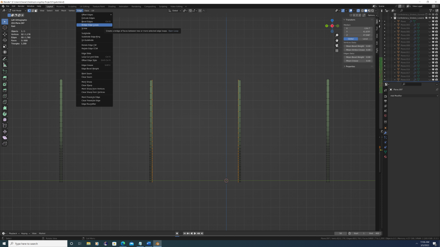
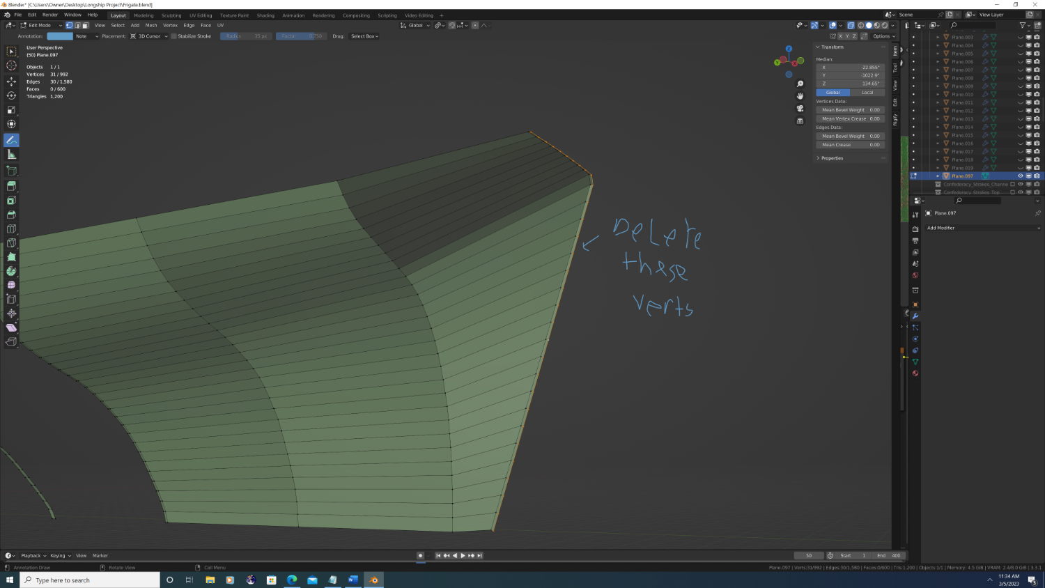
Step #2 (Finale) So joining the pieces together is actually fairly simple, but I do want to call out a couple nuances and "got-ya's" as I go along... 1. I first want to apply the modifiers for the plane arrays along each station line curve, and once again, do this segment by segment. Ergo: I select all planes along the rabbet to bottom of main wale segment Second, I duplicate and apply all modifiers - I duplicated them so I could retain a backup (which is actually what allows me to present this as a tutorial) ['Shift' + 'D', then 'Enter'] for blender users. VERY IMPORTANT - I must apply the modifiers on each object BEFORE I join them. Fortunately, Blender has an add-on that allows modifiers to be applied to every object you have selected. It's called 'Interface: Modifier Tools'. It can be found it under the main menu bar. Select 'Edit' -> 'Preferences' then a box will pop-up. Then select 'Add-ons' on the left-side menu then scroll down till you find 'Interface: Modifier Tools' Click the check box and close the window. There will now be 4 extra buttons at the top of the modifier stack, and the very first one just happens to be 'Apply All'. So with all duplicated planes selected, press 'Apply All', the join them into a single object by pressing ['Ctrl' + 'J']. I then hid the backups from view. Fig 2. The add-ons menu in Blender. Fig3: Screenshot of the plane arrays joined as one object. 2. Now that I have the plane arrays as one object, I want to connect them into one continuous mesh. There are a few ways to do this, but I did it by going into edit mode and loop cutting [Ctrl +R] each array down the middle like so: Once I've bisected at least two plane arrays, I can then select the edges nearest one another and bridge the edge loops. TIP - make sure x-ray is turned on or not all verts may be selected. IMPORTANT - the 'Bridge edge loops' command has several options in the resulting pop-up window. Make sure that 'Connect Loops' is set to 'Open Loop' and that you have the 'Merge' checkbox checked. This may sound strange, but I then need to dissolve the resulting edge so that the only vertical lines in the mesh are that of the station lines. I will be adding interpolated cuts later, but I'm speaking from many of my past mistakes when I say that now is not the time to add them Anyway with the edge still highlighted just press 'Delete' and choose 'Dissolve Edges' from the pop-up box. Caveat - the bookends: When I got to work on the arrays nearest the bow and stern, I have an extra edge of vertices (because there's not an array beyond that to which a connection can be made). Simply delete these vertices. 3. Lastly, I just repeat the above steps for each plane array, then do the same for the upper hull segments. Note that each hull segment will be it's own object for now, and that is fine. (FYI - I'll explain the use of the subdivision and why the foremost array is off the ground in the next step. Smooth sailing to you all, - Nate


- 107 replies
-
- 3
-
-
- Frigate
- Confederacy
- (and 1 more)
-
Step#2 (Continued again...) Before we can join these together, we need to repeate the process for the upper segments. My segments are as follows a. The top of the rabbet (which also the origin of the overall ship , same as it is on plans) to the bottom of main wale (already covered in last post) b. The main wale c. The top of the main wale to the bottom of the channel stringer. FYI - I'm calling this the 'gun wale segment' because within this area runs a gunwale stringer, though interestingly, it neither follows, nor influences, the overall run of the strakes (more research req'd) d. Bottom of the channel strake to the top of the lowest cap rail (forgive me, I don't know the proper name for this piece if there is one) e. The top segment, which is actually multiple segments, but luckily the change in the arc along between the curves is minimal - so I was able to do it as one piece. The 'yucky' part is that on ever level above the first one, we need to also align the 'floor' of each plane before we scale it vertically. This, sadly, doubles the workload on each one... The next level up would be the main wale. Now, the models I've seen depict two heavy duty stringers along the top and bottom edges, and the planking in the middle is cut into a series of scarfs, lap-joints, and other assorted jigsaw pieces lol. However, the total width appears to be around 5 strakes, so that's what value I used. If you're interested in following along the steps are: 1. duplicate the plane array from the lower segment along the same station line 2. change the array modifier to the number of strakes in the new segment (5 in this case) 3. In object mode, press 'g' to grab the whole thing, then 'z' to move it upward to align the bottom of the new array with the top of the array segment below it. 4. Go into edit mode and move the top edge up or down so the highest strake aligns with the next curve up (same as we did for the previous section) After the main wale was done it was simply wash, rinse, repeat until all station line curves within each hull segment had an array of planes on it. And, thankfully, I was finally ready to join the hull into a single object...


- 107 replies
-
- 1
-
-
- Frigate
- Confederacy
- (and 1 more)
-
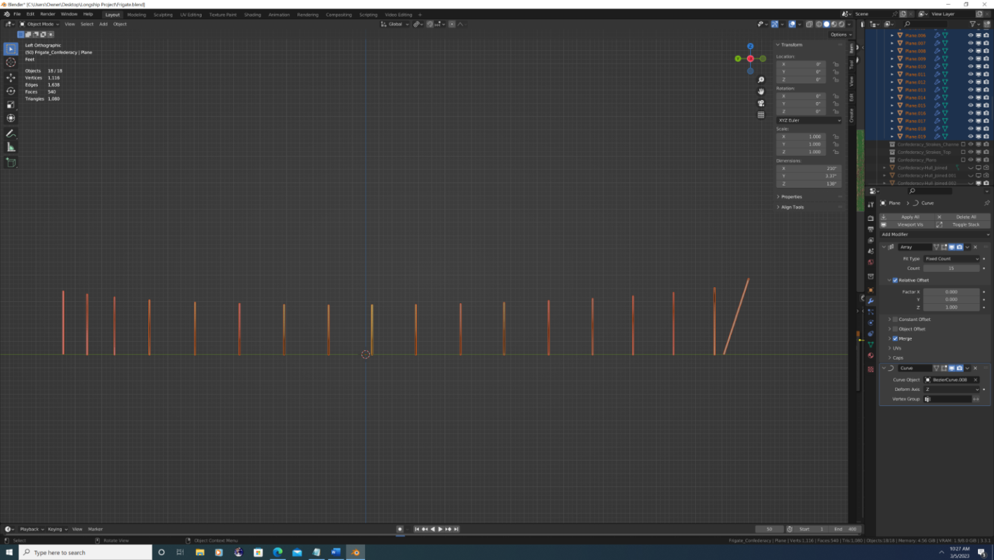
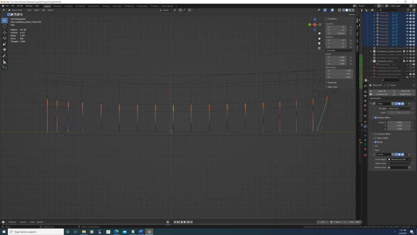
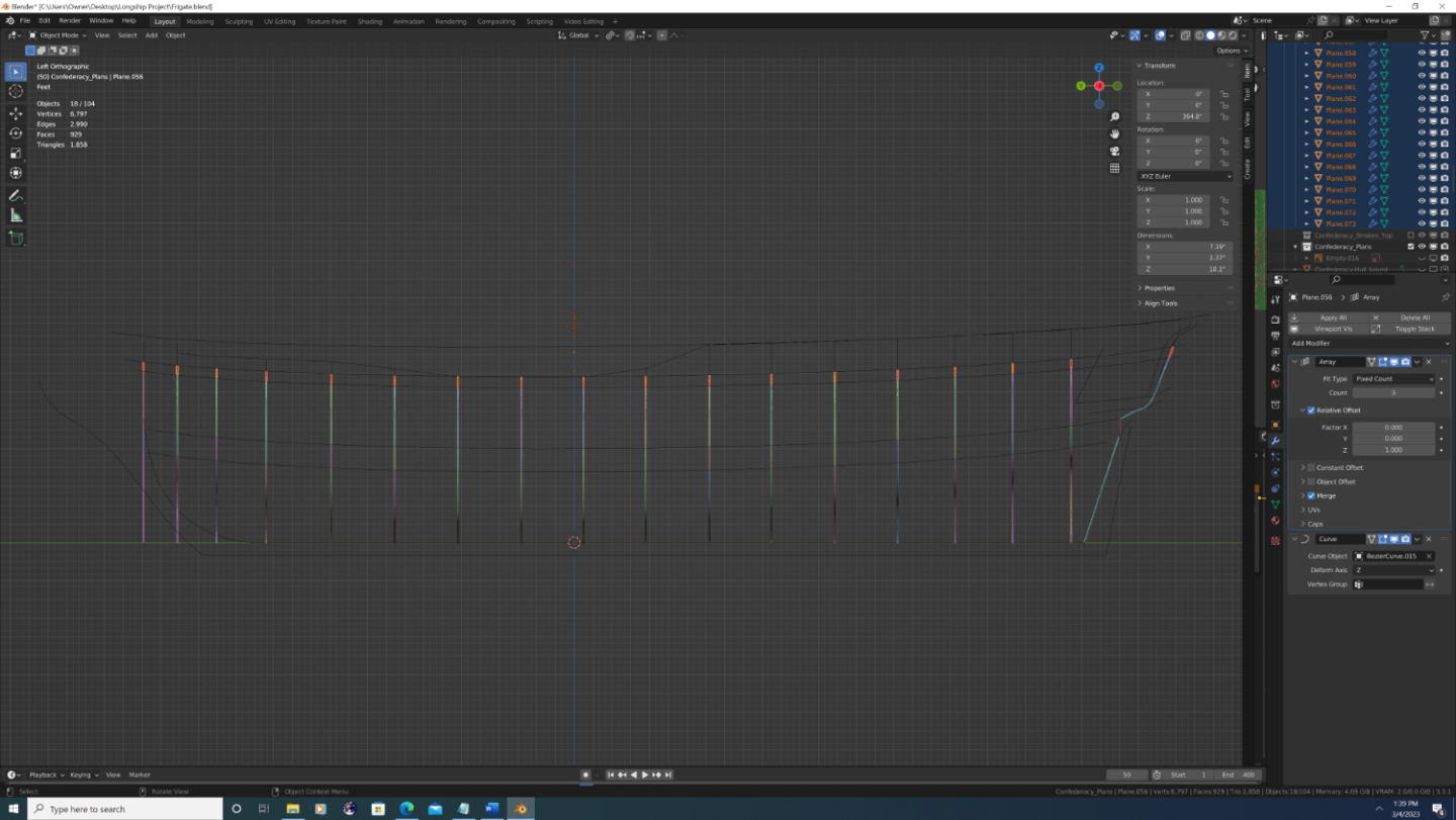
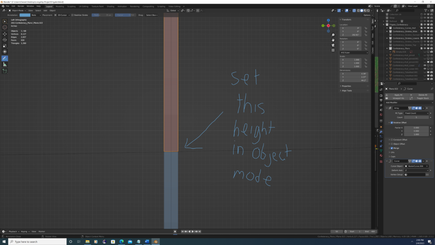
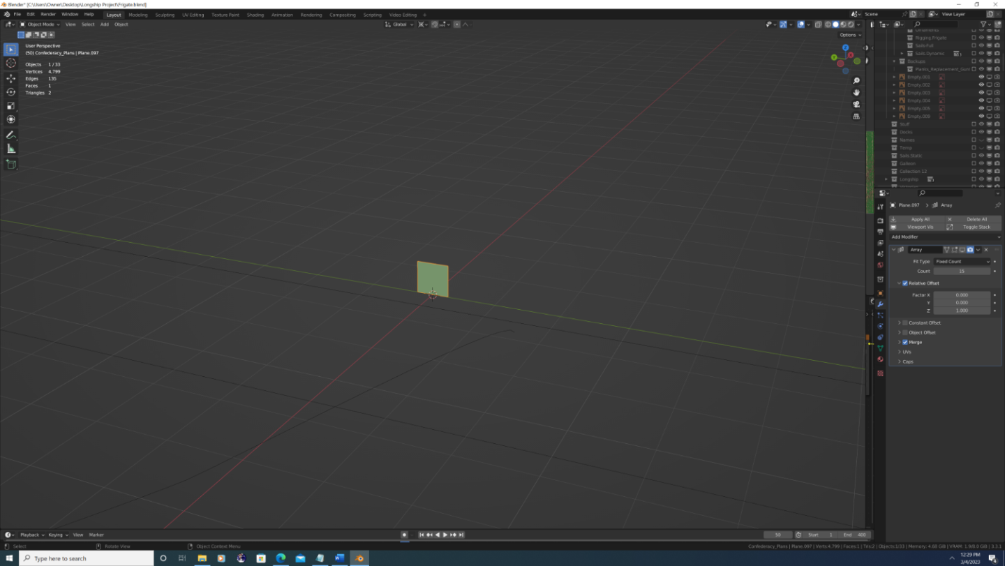
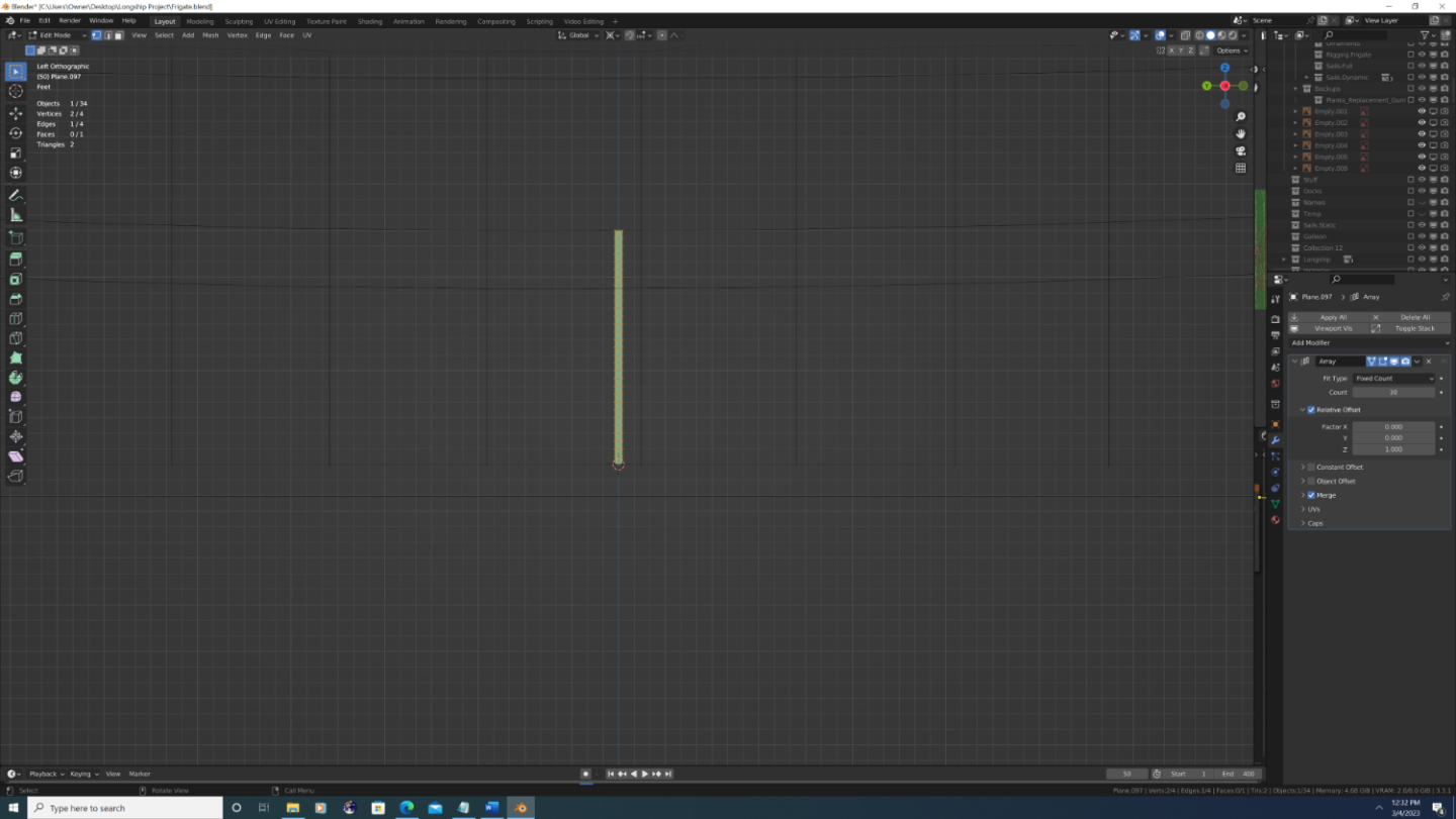
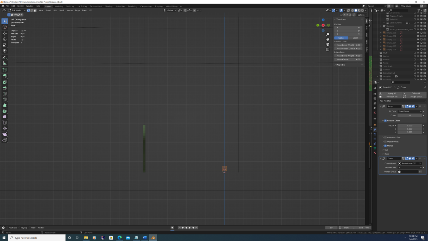
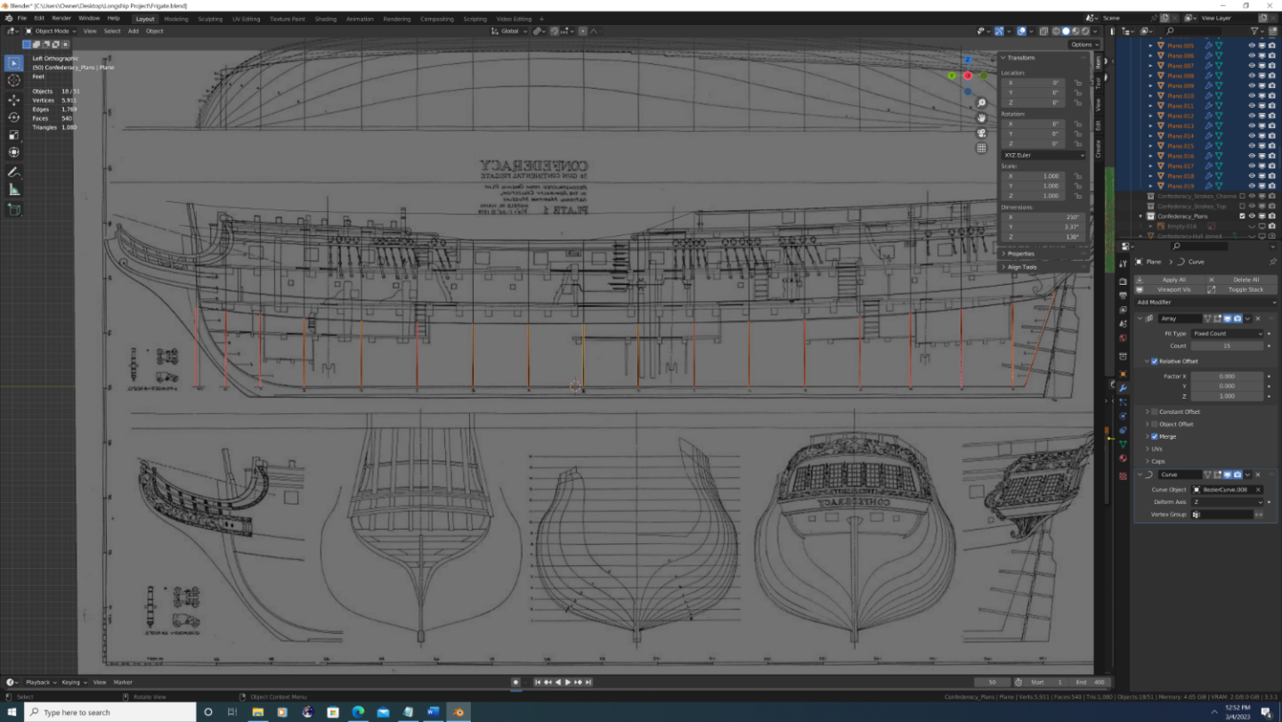
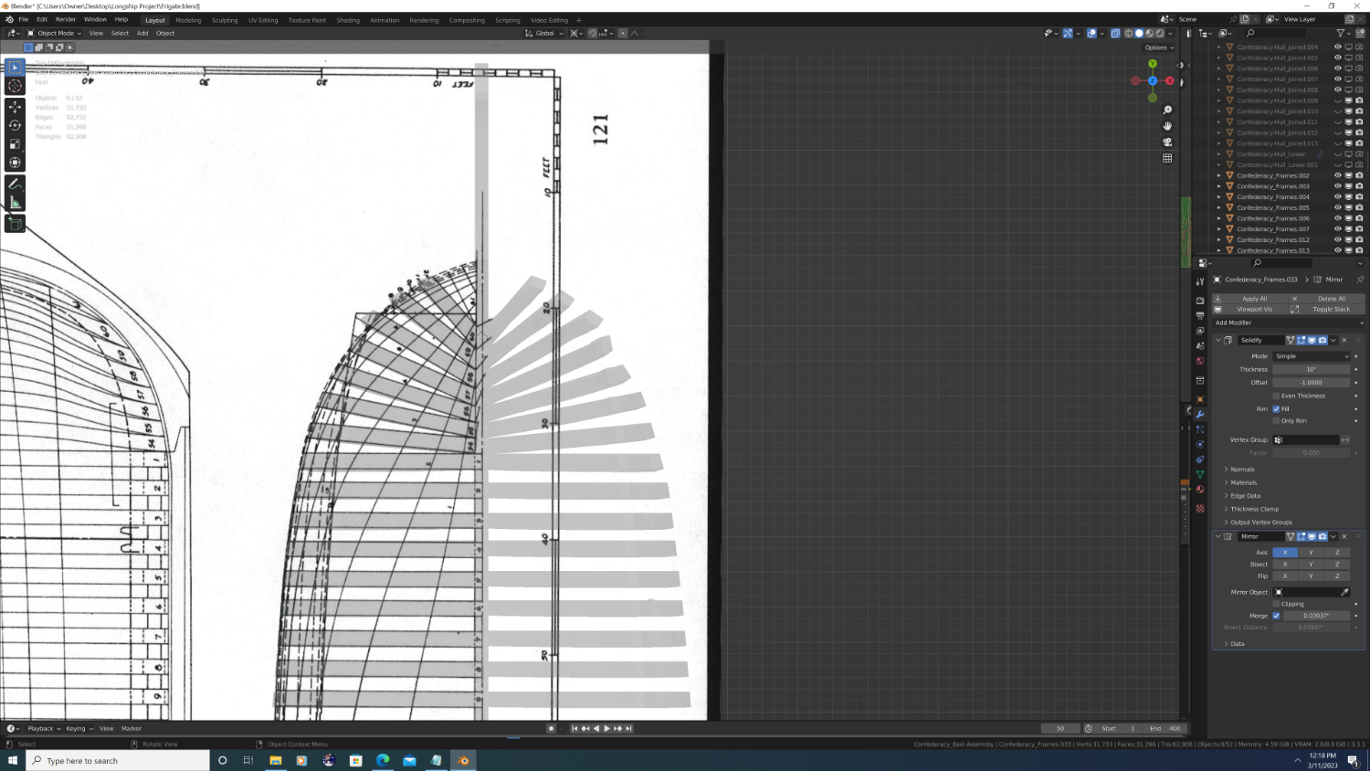
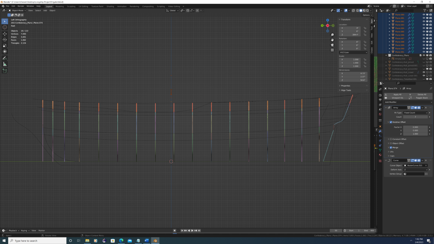
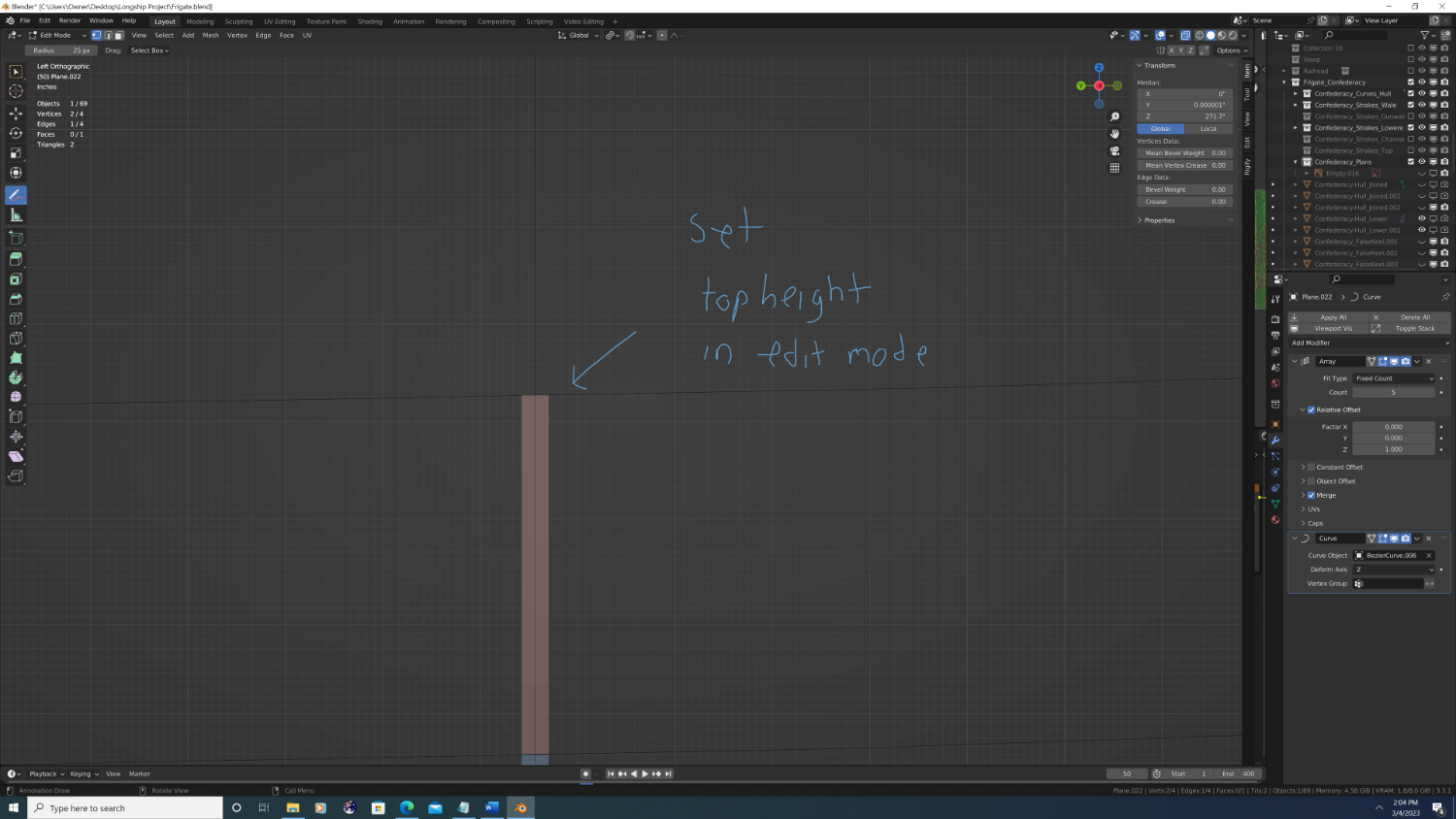
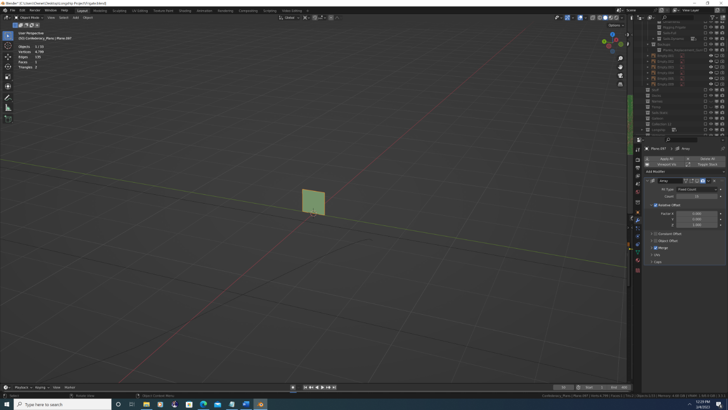
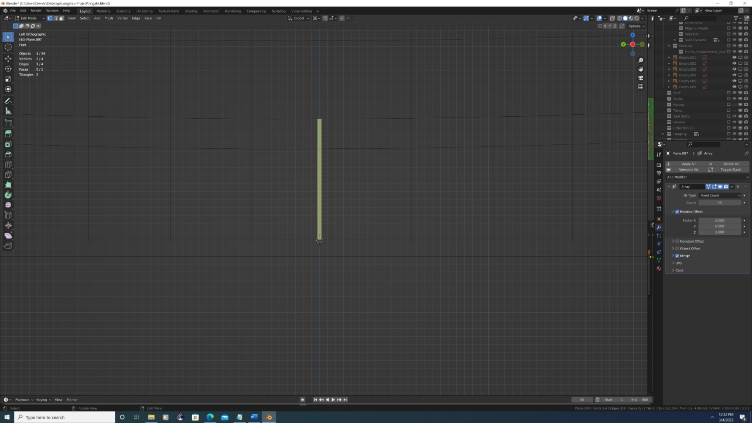
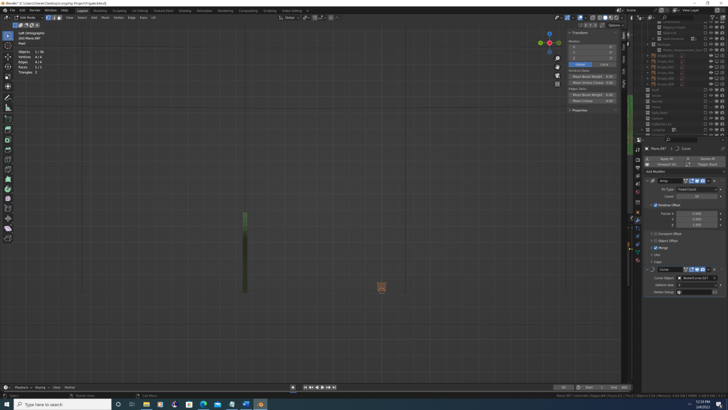
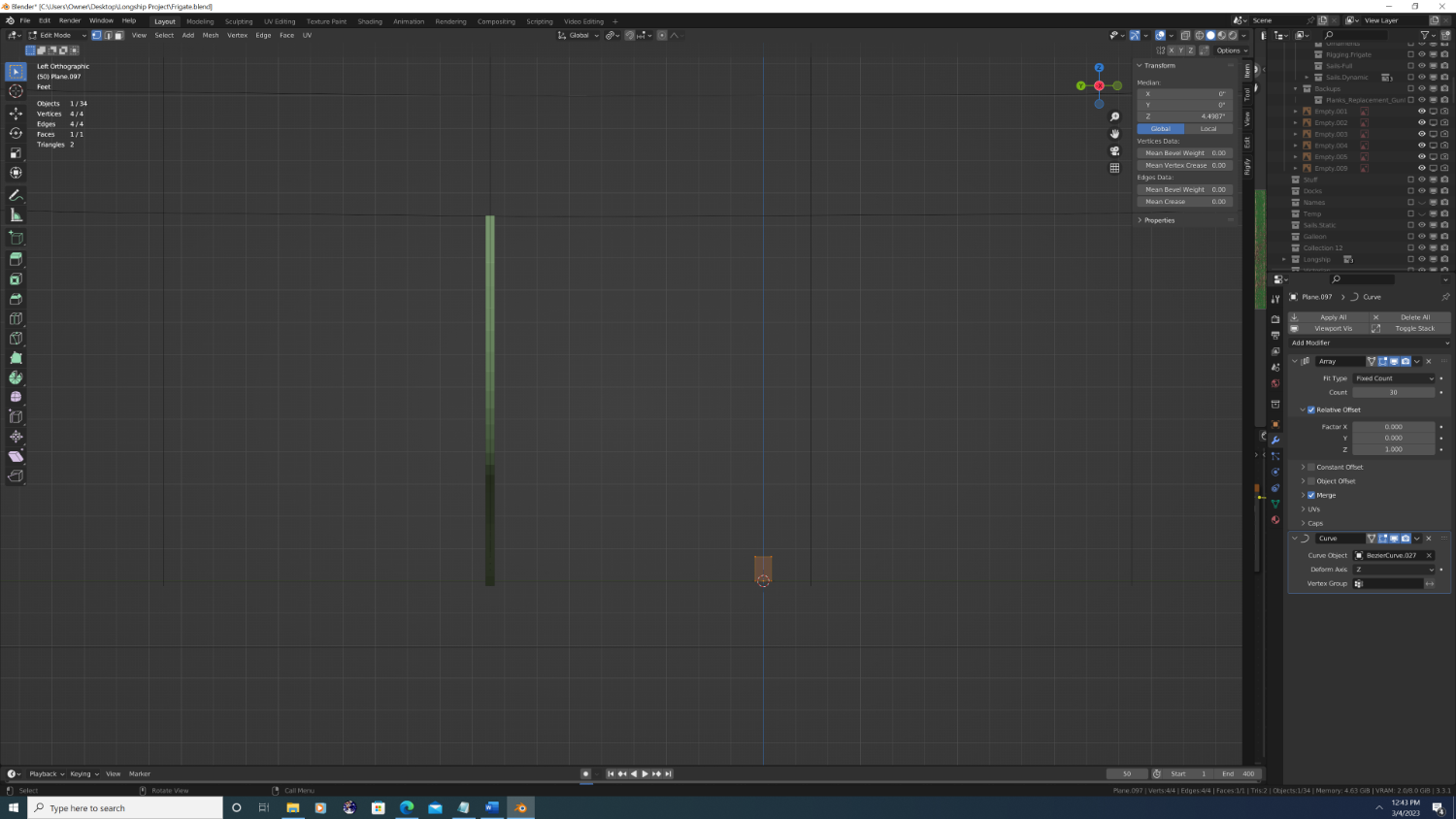
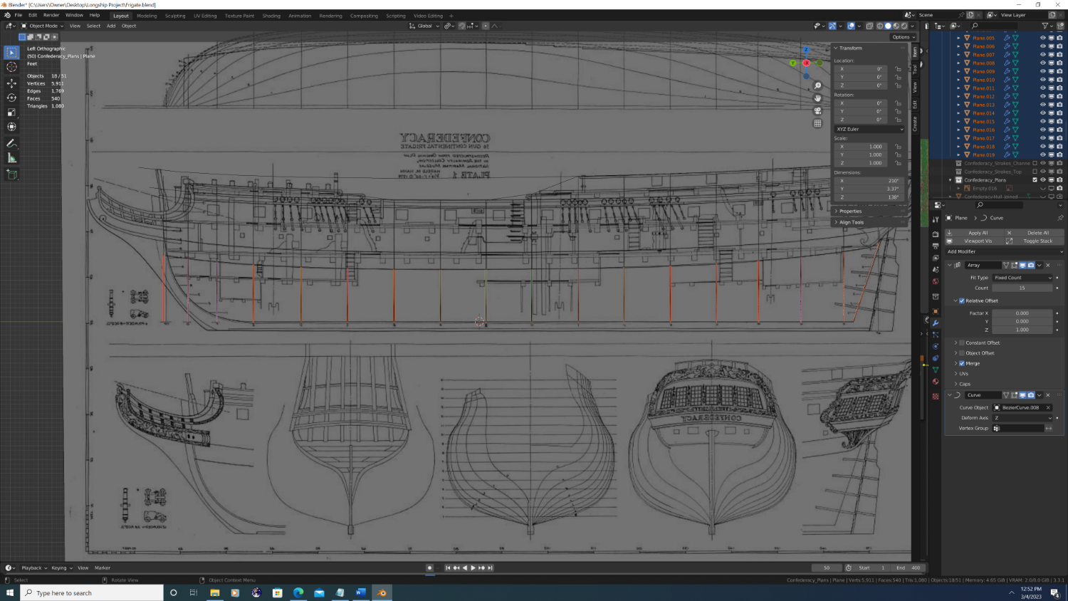
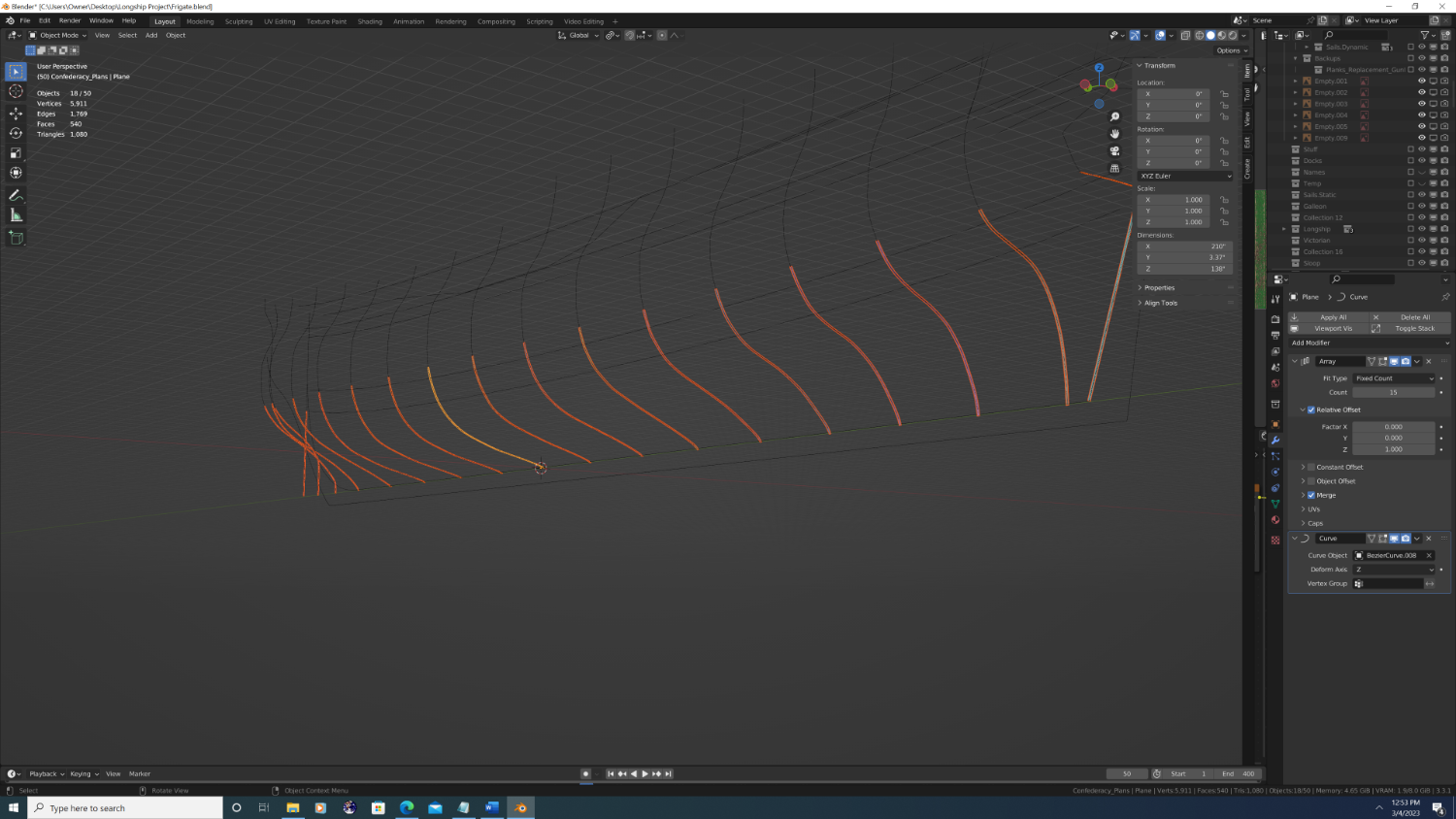
Step #2 (Continued) So what I want to do is 1. Draw additional curves that mark the top and bottom of the main wale, the bottom of the channel strakes, and different levels of planking. Note: I DO care about inflection point s in the overall run of the planking. I DO NOT care about things that are cut into the planking such as gunports or sweep ports. 2. I added a 2D plane (6in X 6in), rotated it upright with the bottom edge flat at location z=0 3. I then added an array modifier (z-axis) equal to the number of strakes in that section (My research conflicted a bit here as my sources showed anywhere between 25-30 plank strakes from lapstrake to bottom of the main wale) I went with 30, under the assumption that it's easier to later subtract than add 4. Next, I added a curve modifier with the deform axis set to 'z', then I used the eye dropper to choose one of the station line Bezier curves. 5. Obviously, it doesn't reach anywhere near the lower edge of the main wale so to fix this I went into edit mode and grabbed the top two verties and moved them upwards until the result reached the appropriate height. 6. When done with that segment, I simply duplicated the plane and changed the 'curve object' in the curve modifier to be the next station line. Each time I would then go back into edit mode on the new plane and readjust the height of the top edge so that the top of the 30th plane would touch the bottom of the main wale. When done, it looks like this:


- 107 replies
-
- 2
-
-
- Frigate
- Confederacy
- (and 1 more)
-
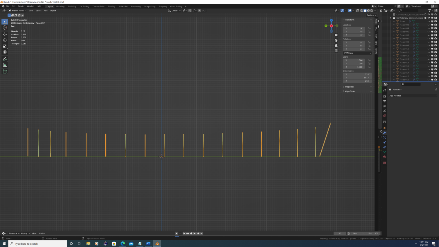
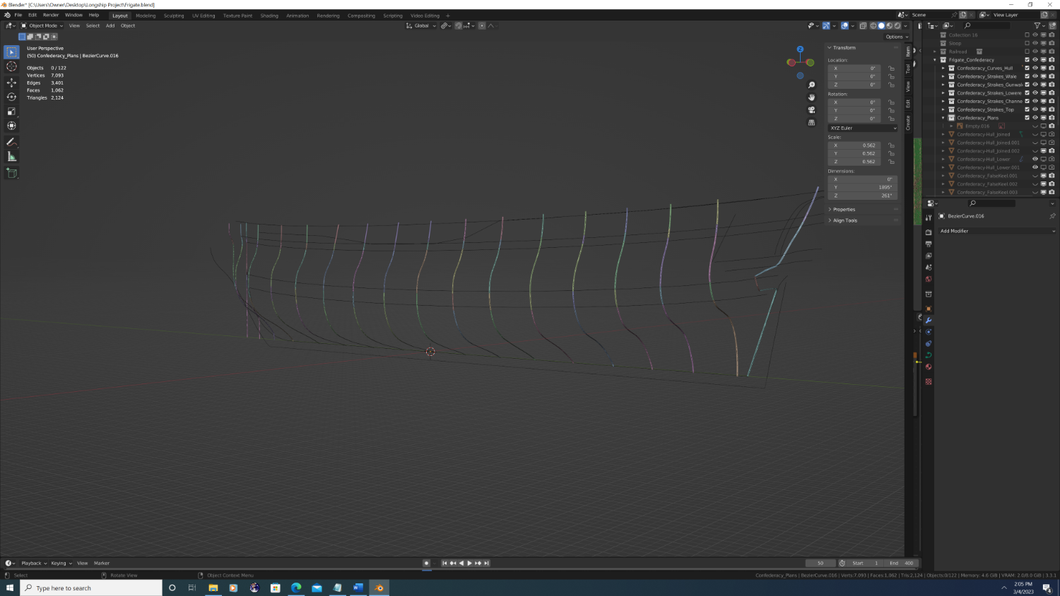
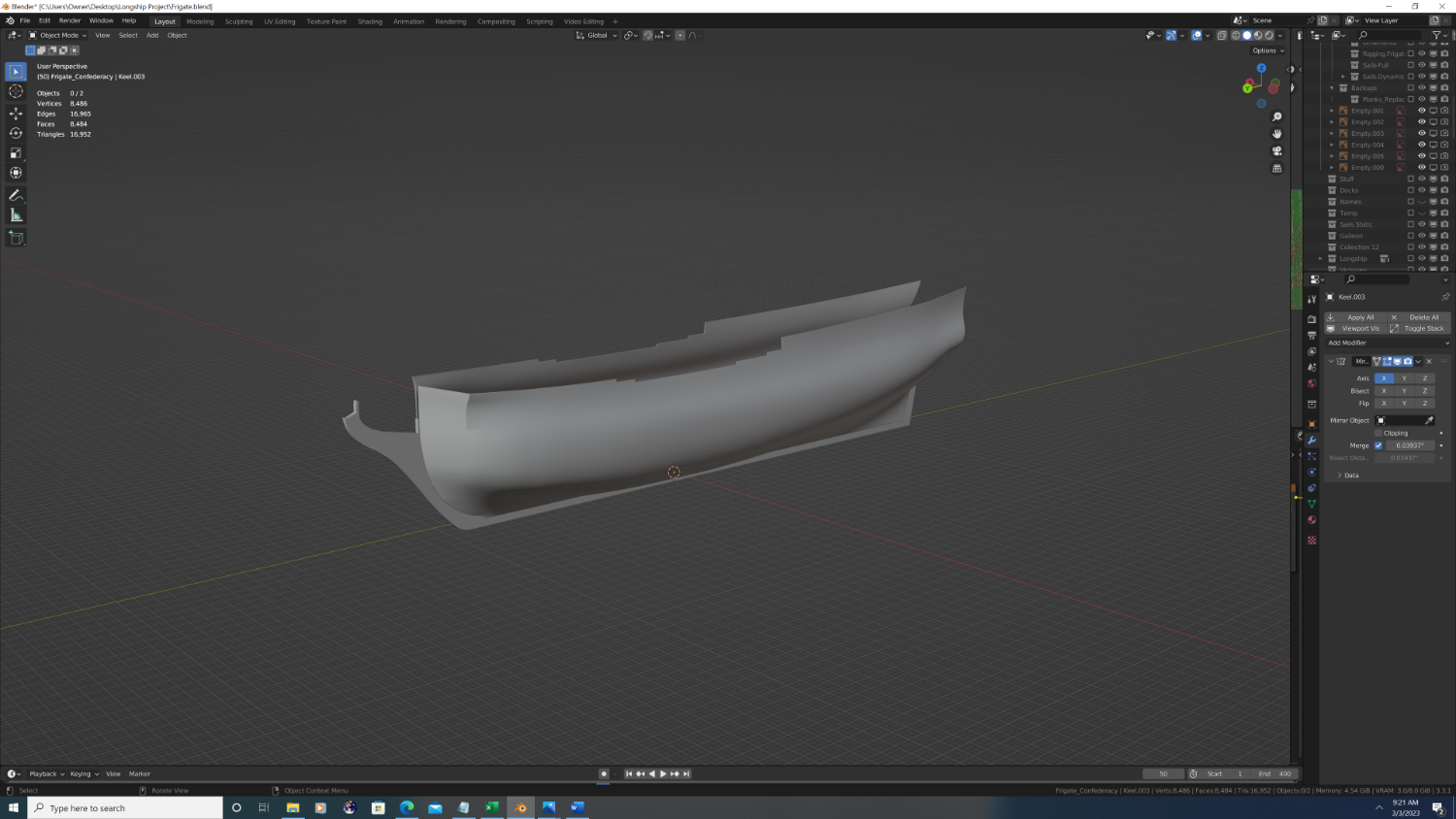
STEP #2 Form the shape of the hull Put simply, in this step we will create a continuous, flat (palinar) mesh that forms the shape of the hull. This is both my favorite and least favorite part of any build. If done right it will yield stunning results, and make the planking process a hell of a lot easier down the road. If done wrong, it will lead to major shading issues that appear as 'dents' in the hull or it can lead to insurmountable topology problems, such as I experienced with rose. So as not to seem arrogant let me say up front that I have never gotten it right. That said, this is where I have a new approach I want to try out: I want to have the mesh not only conform to the shape of the hull, but to also have the topology so each strake can be easily modelled. On a real ship, as the strakes curve around the hull they are wider in some spots, narrower in others, and are even cut as diagonal scarfs in some areas. Put another way, what we really need to care about is the latitudinal 'arc' at key points like the main wale, gunwale, channel strake and any cap rails at different levels (ie. the forecastle, quarter deck). Note that as I cut away the extra geometry, it still extends beyond the plans in some spots, and that's okay for now: strakes that are too long can be fixed, strakes that are too short cannot be fixed. So that's the goal, but how do we get there from our Bezier curves in step #1...?
- 107 replies
-
- 2
-
-
- Frigate
- Confederacy
- (and 1 more)
-
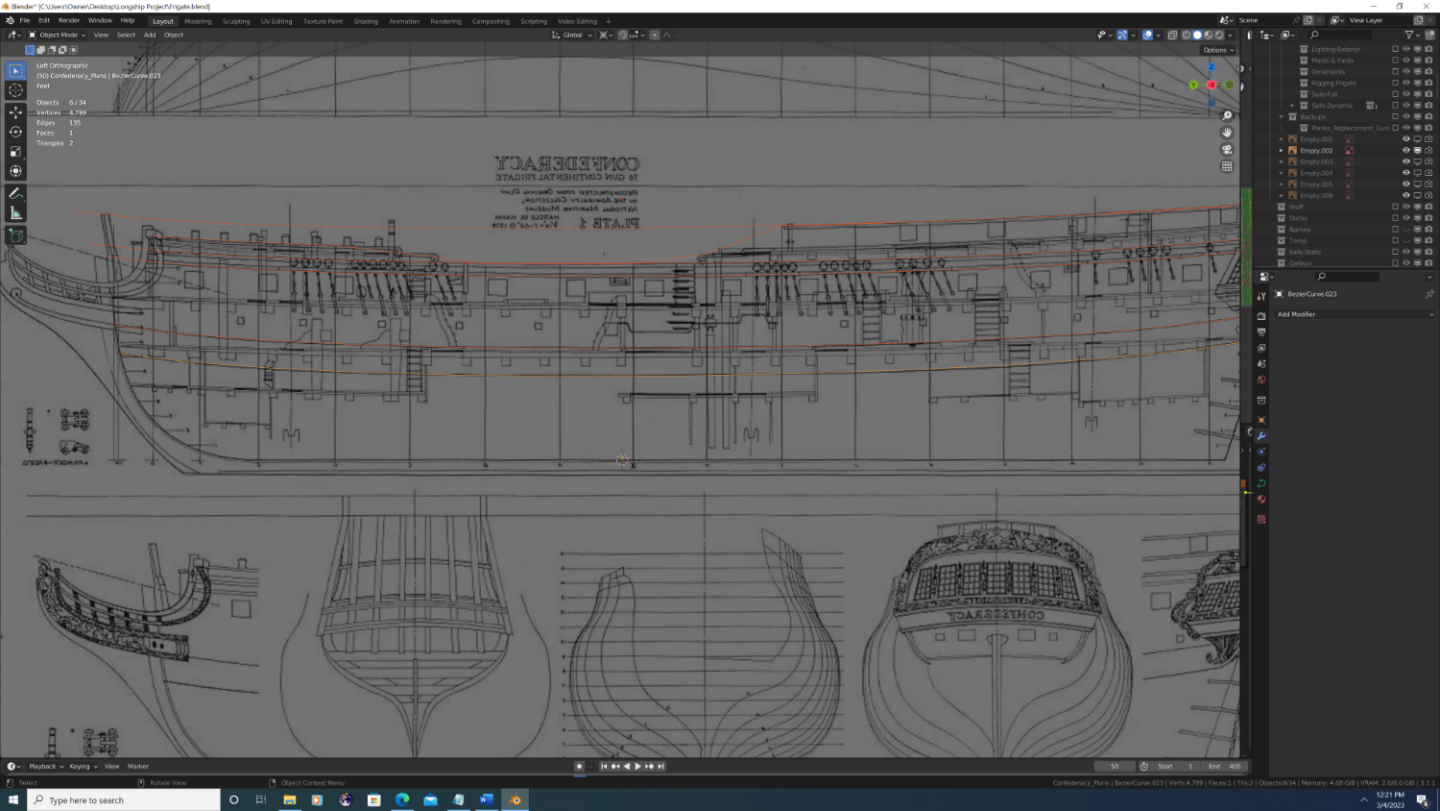
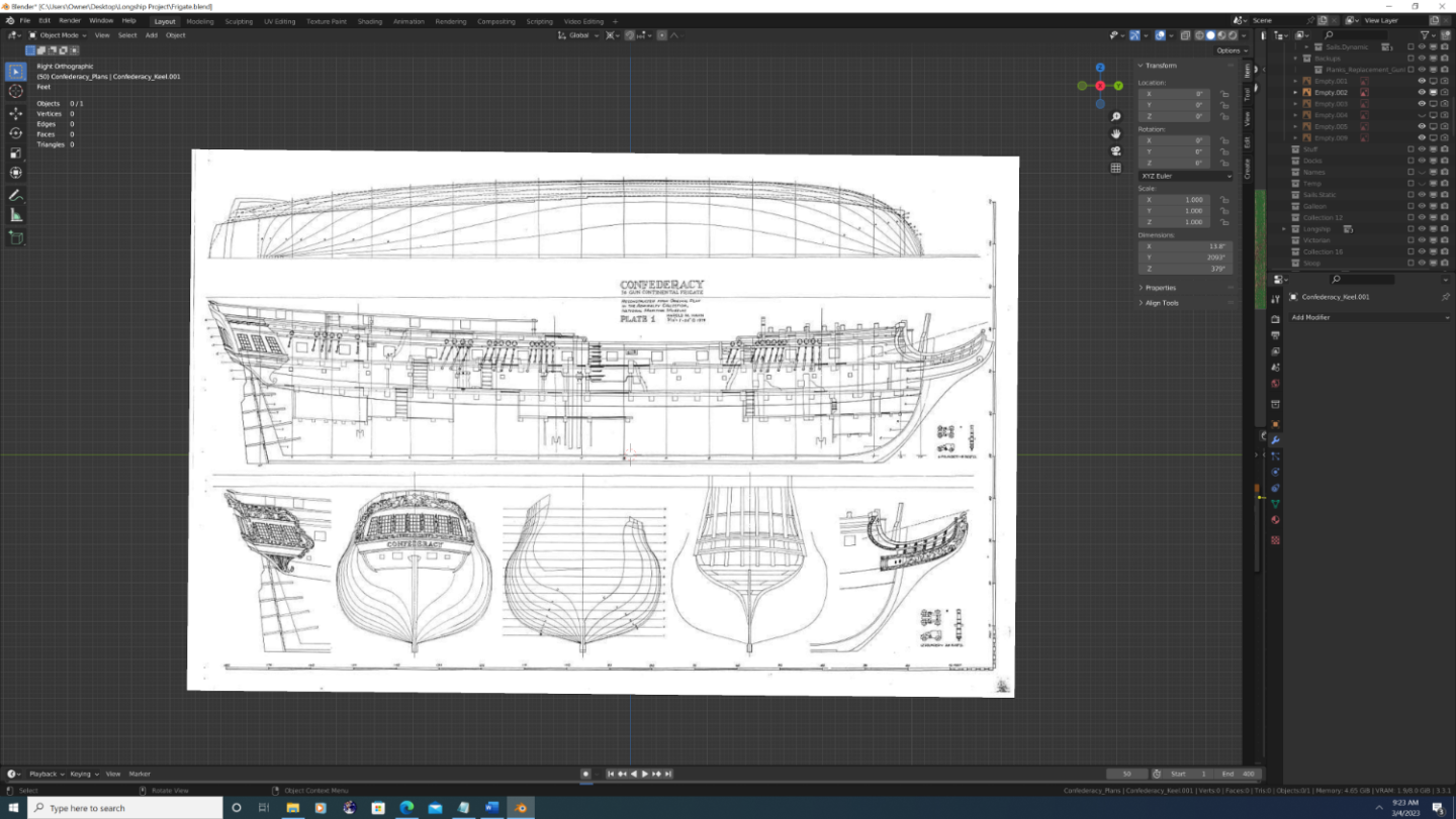
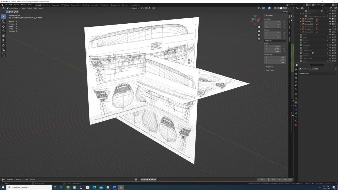
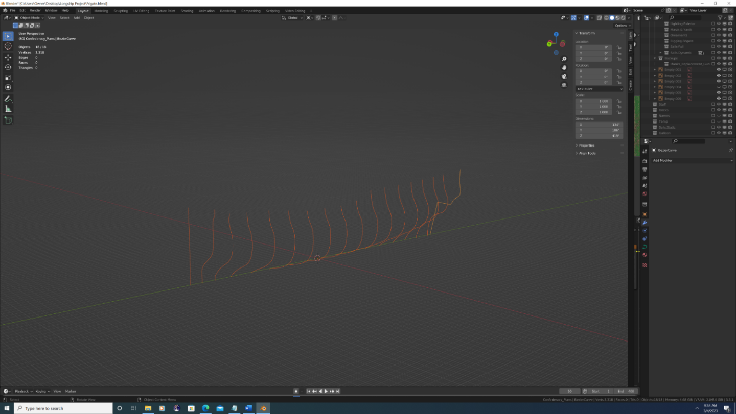
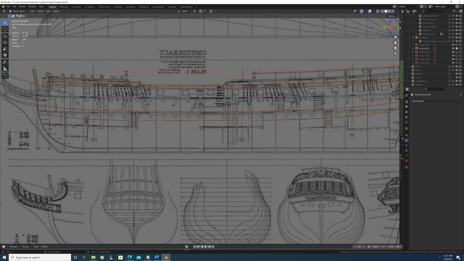
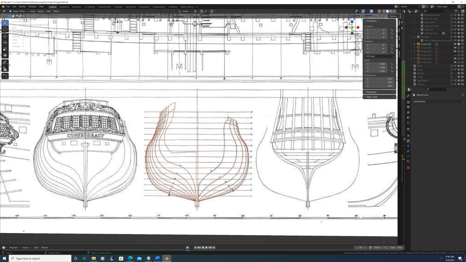
Okay, here we go... So, the obvious first step was to identify suitable plans. I first greedily gathered up everything I could find on Confederacy, good, bad, or ugly. Then I began the arduous process of sifting through them piece by piece. I ultimately decided upon Harold M. Mann's reconstructed admiralty plates circa 1979 for the National Maritime Museum. His plates are not completely without distortion, but it's minimal, and most importantly, they are complementary to one another. So I imported them, used blender skew and rotate them ever so slightly (so the parallel lines are in fact parallel), then finally I scaled them. Then I aligned each plan in the set with the appropriate axis from which I'd be working on them. Next, I drew out the station lines. I flipped/mirrored the bow station lines to the same side as the others, then positioned each one front to back using the half-breadth plan. Then I used the aft most station line to shape the edge of the planking as it would appear inside of the transom and quarter gallery.

- 107 replies
-
- 6
-
-
- Frigate
- Confederacy
- (and 1 more)
-
Hey Folks, I am both honored and humbled to announce my next Blender build: USF Confederacy is my 4th ship in Blender, yet will be my first attempt at a full historical recreation. While ‘Rose’ will always be my first love, I plan on taking many lessons-learned from my little-brig-that-could and apply them to a project on a grander scale. Goals of USF Confederacy Build: Accurate With Rose, I proved to myself that it is possible to do comprehensive rigging and sails on a 3D model. I had seen some absolutely stunning 3D builds on MSW before I joined, but I noticed that 99.9% of the threads stop during the rigging process (I’m talking about full digital builds; not those done to 3d print parts later). Why did so much excellent work not get completed? Well, because in the 3D world rigging is actually where the overwhelming majority of the work takes place. I hoped to be among the first, because visually, it’s the yards, spars, sails and rigging that occupy the majority of the space taken up by any model ship. Anyway, with Confederacy I want to bring the same level of realism to the keel, frames, planking, carvings and fittings – and have it be historically accurate this time. Thus, any deviation or parts taken from the designs of other ships is to be well planned out and documented up front. Light Rose clocks in at 6.2 million vertices and requires 14Gb of RAM and 7.5Gb of VRAM to render… without water, clouds, or anything else in the scene. Even if I never sell or distribute her (I’m not in this for the money lol) I do plan on one day doing renders of Rose duking it out with other ships in an epic naval battle, or perhaps sailing up the Thames in Victorian London. Ergo, I must do more with way, way less. I’ve long been imagining/theorizing techniques to reduce geometry/improve performance and I am genuinely excited to try them out. Beautiful Photoreal or bust, ‘nuff said. Excited to share – will post steps from the planning phase later today. Best, -Nate

- 107 replies
-
- 5
-
-
- Frigate
- Confederacy
- (and 1 more)
-
Hey Everyone, I know I'm long overdue for an update post on Rose, so here it is... List of changes: 1. Mounting brackets securing the dolphin striker to the main bowsprit cap have been added 2. Dolphin striker color changed to black 3. Leading edge of the cutwater has been subtlety beveled from Gripe to tip of the bobstay piece, then inboard to the gammoning knee 4. Double jeer blocks added and cathead rigging completed portraying the anchors in a stowed position resting atop the fore cap rails 5. Twin 18-pound bow chasers placed on the gun deck 6. Fore Topgallant bowlines added 7. Buntlines added to the Fore topsail and belayed to the 4th & 5th pins on the fore companion’s pinrails 8. Tacklines have been added and belayed to the bumpkins and to thimbles above the main wale for the fore and main course sails, respectively 9. Fender blocks added to the outer hull 10. Grates on the main deck redone from scratch, including screws That's all for now - feedback always welcome!
.thumb.png.1482a58547e84012969dda37c3113bbc.png)
.thumb.png.3f12b9c8b43222613be1e6ecd4723a1d.png)
.thumb.png.d854c4fb29d0e0f4834acdc8c08771b1.png)
.thumb.png.ed2b94d8ae91295b869a642157196ce9.png)
.thumb.png.1043612ad3fd9db0e791cd87d2ccdec5.png)
.thumb.png.7d516a7b33e7a380df112982eb0e507f.png)
-
This is the image I used to do the crow's feet. Yes, there are about 10-12 holes in the curved part of the futtock They are actually lashed in series, as an over-under alternating weave.
-
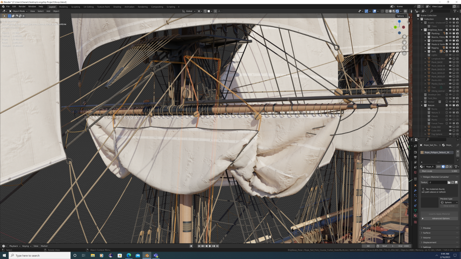
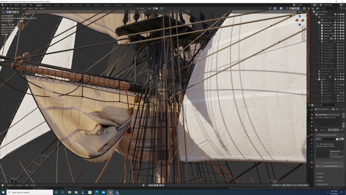
Hey Folks, So I was wondering if someone can help educate me on how sails come to be neatly furled atop the yard, given that: 1. The Buntline blocks rest in front of the yards and the Buntlines themselves fall in front of the sail to where they are tied at the foot of the sail. 2. The Clewline and Clewline block rest behind the yard. Basically, the Buntlines and Clewlines seem to want to fold the sail in opposite directions, which to me seems very non-conducive to a clean fold/roll of the sail cloth... What am I missing? Thx in advance, -Nate PS - please ignore the problem with the stirrup/horse protruding through the sail (I have yet to fix this) Figure 1. Buntlines Figure 2. Clewlines (and tackline at the sheet block)

-
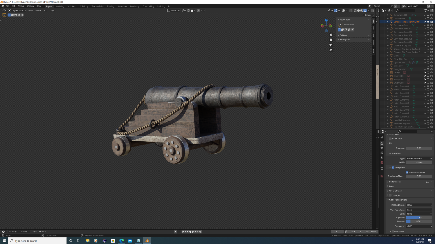
3D cannon barrels
3DShipWright replied to allanyed's topic in CAD and 3D Modelling/Drafting Plans with Software
Hey Allan, Sounds like you already got a number of volunteers, but I'm happy to offer my services as well. Just let me know if I can be of assistance. -Nate
-
FYI, on a ship this size, there there would also be a third post between the mast cap and the futtock on each platform (see below).
-
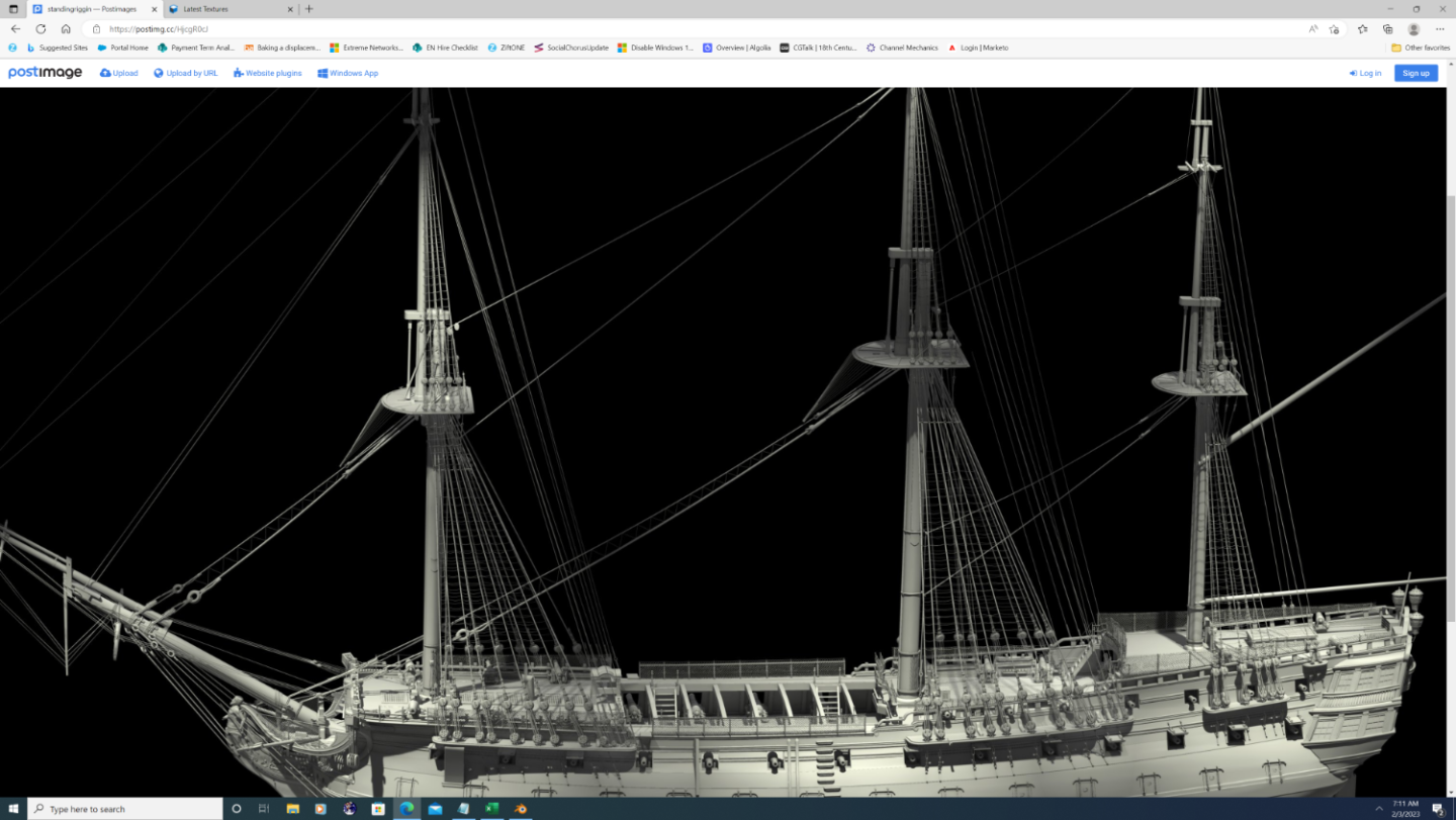
Looking good Kurtis! A couple minor notes: 1. Your deadeyes are spaced too far apart... To climb the shroud, the crew must be able to step from the deck or rail onto the lowest ratline (or spacing block), and logically, these have to be above the upper deadeye in each set. 2. It looks like you wrapped each shroud around the masthead above the futtock in the correct order (well done!). However, from here it looks like the mast head remains cylindrical instead of squaring out... It should look like this: 3. Finally, if there's any rearward lean/tilt to the masts, the futtock and cross-trees should be angled forward (to provide a flat perch), but the mast cap remains100% perpendicular to the lean of the mast. I did this wrong on mine and it later caused lots of problems with the rigging. Not saying you did this part incorrectly, just a lesson learned from my project. Keep up the good work, -Nate
-
@allanyed - Unfortuneately, I can't mark both replies as 'solution', so I just wanted to thank ya for the addl. explanation. -Nate


.png.ec5dda53dfb7de6b3464cb5411240224.png)
.png.d4493b50d88f40e79a511a6de48e20e4.png)
.png.23bea674f436d0d8f6ca6dce527a5874.png)
.png.f12bde3d17e7b3fc078dda4c1a57e331.png)
.png.ad3860bc12a92828ea969553951473ff.png)
.png.8e2fd99b22af4c8fd9e9bbebbca8663e.png)