HOLIDAY DONATION DRIVE - SUPPORT MSW - DO YOUR PART TO KEEP THIS GREAT FORUM GOING! (Only 36 donations so far out of 49,000 members - C'mon guys!)
×


DonBMichigan
-
Posts
60 -
Joined
-
Last visited
Content Type
Profiles
Forums
Gallery
Events
Everything posted by DonBMichigan
-
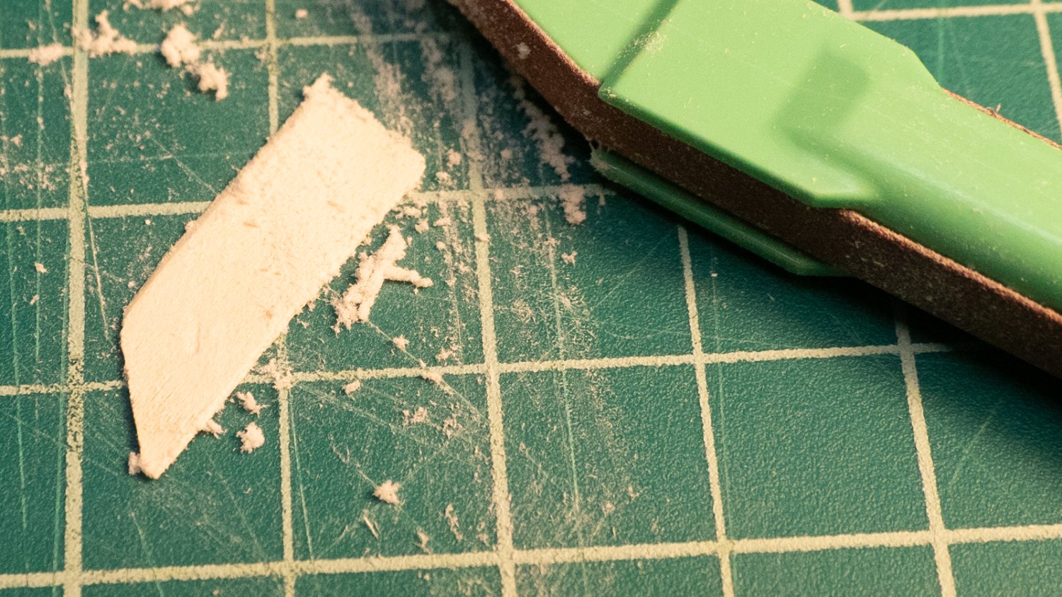
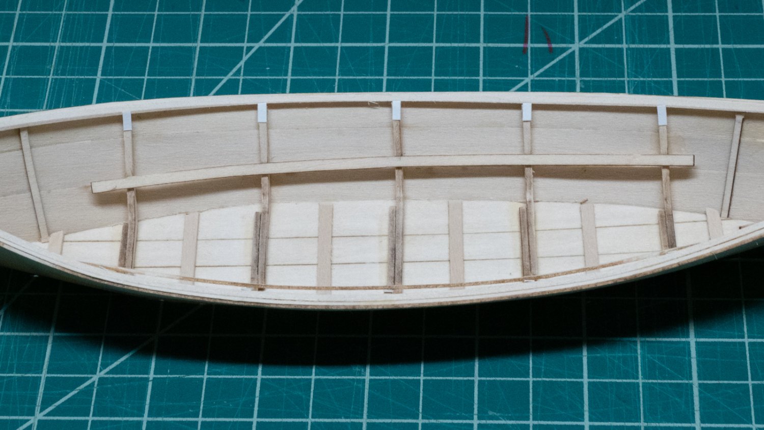
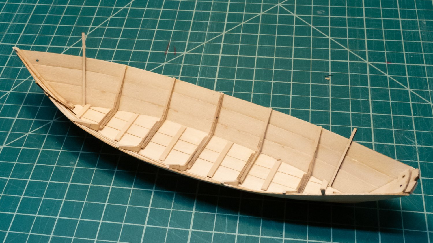
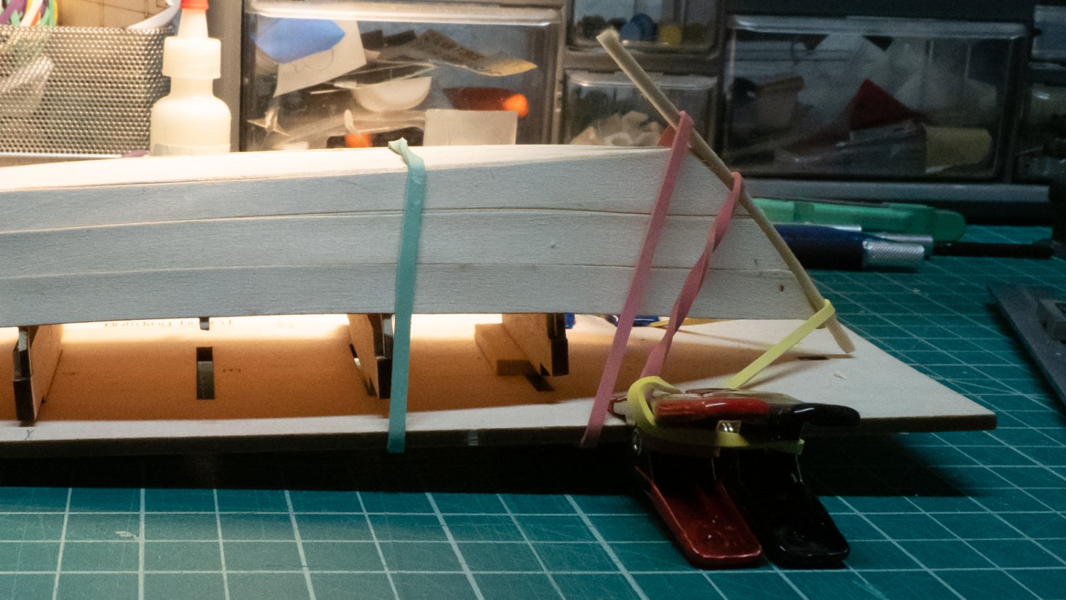
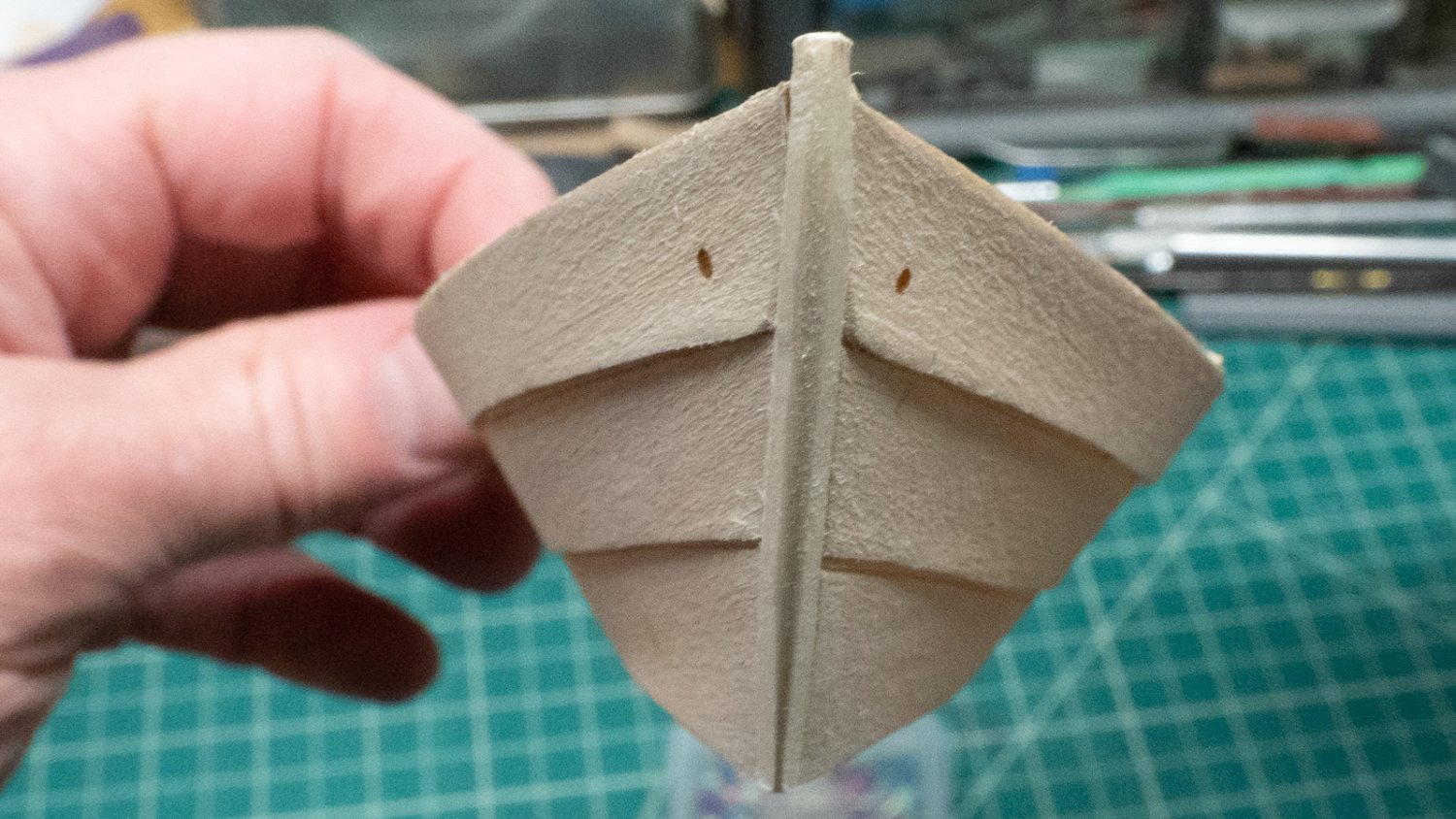
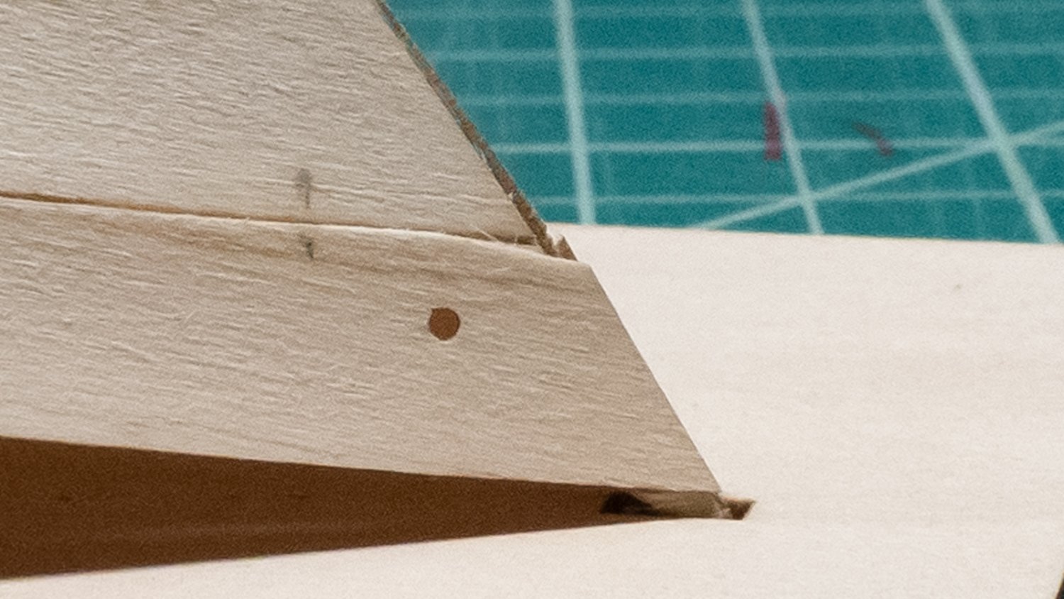
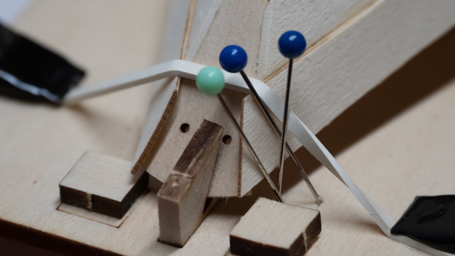
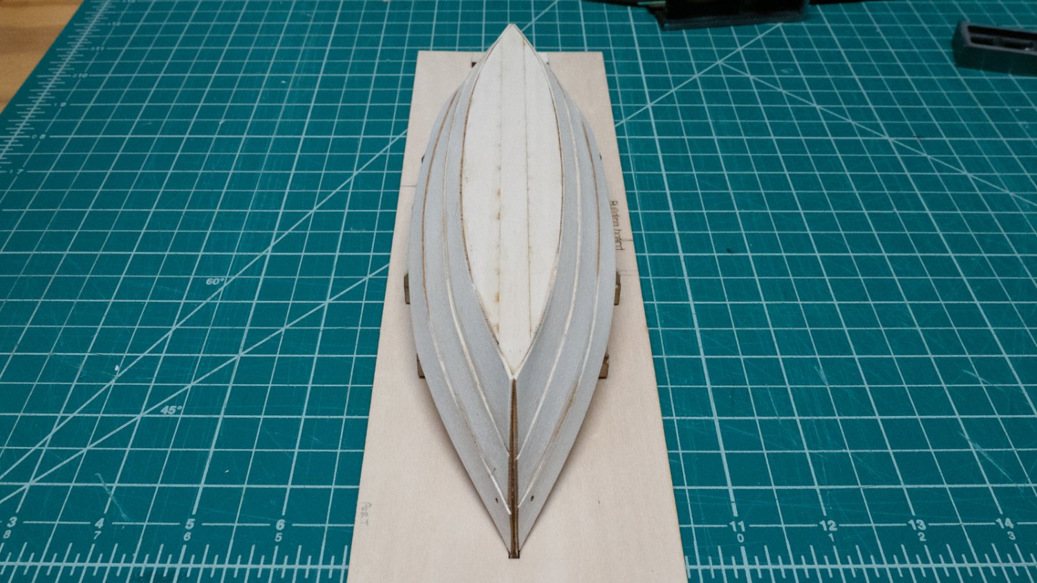
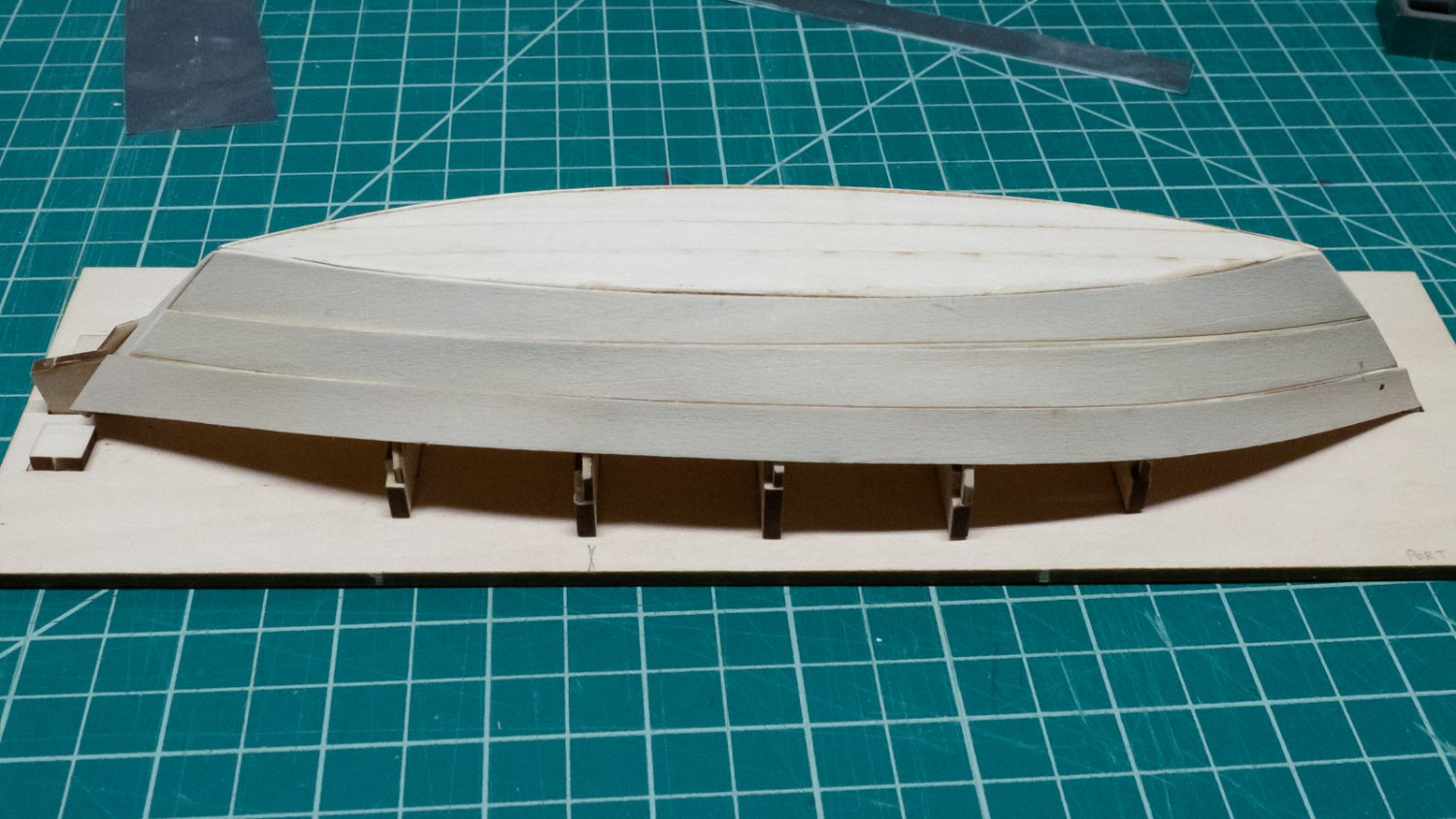
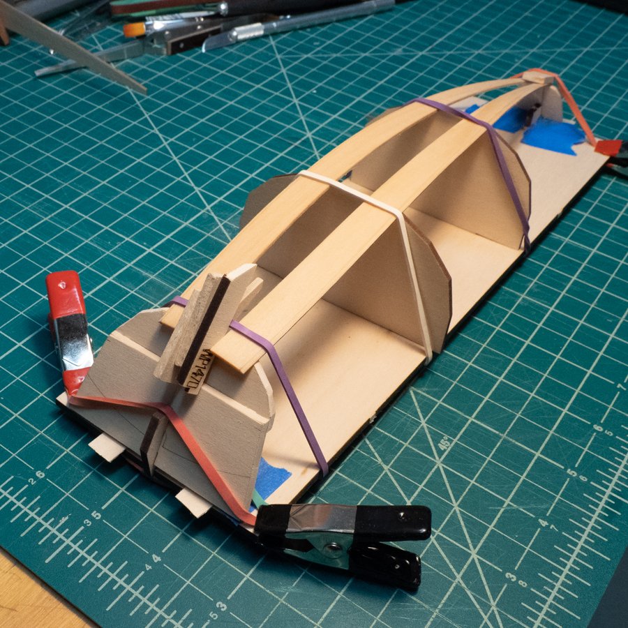
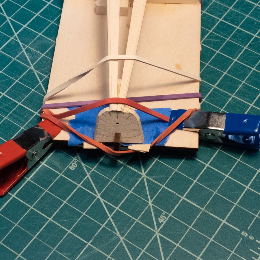
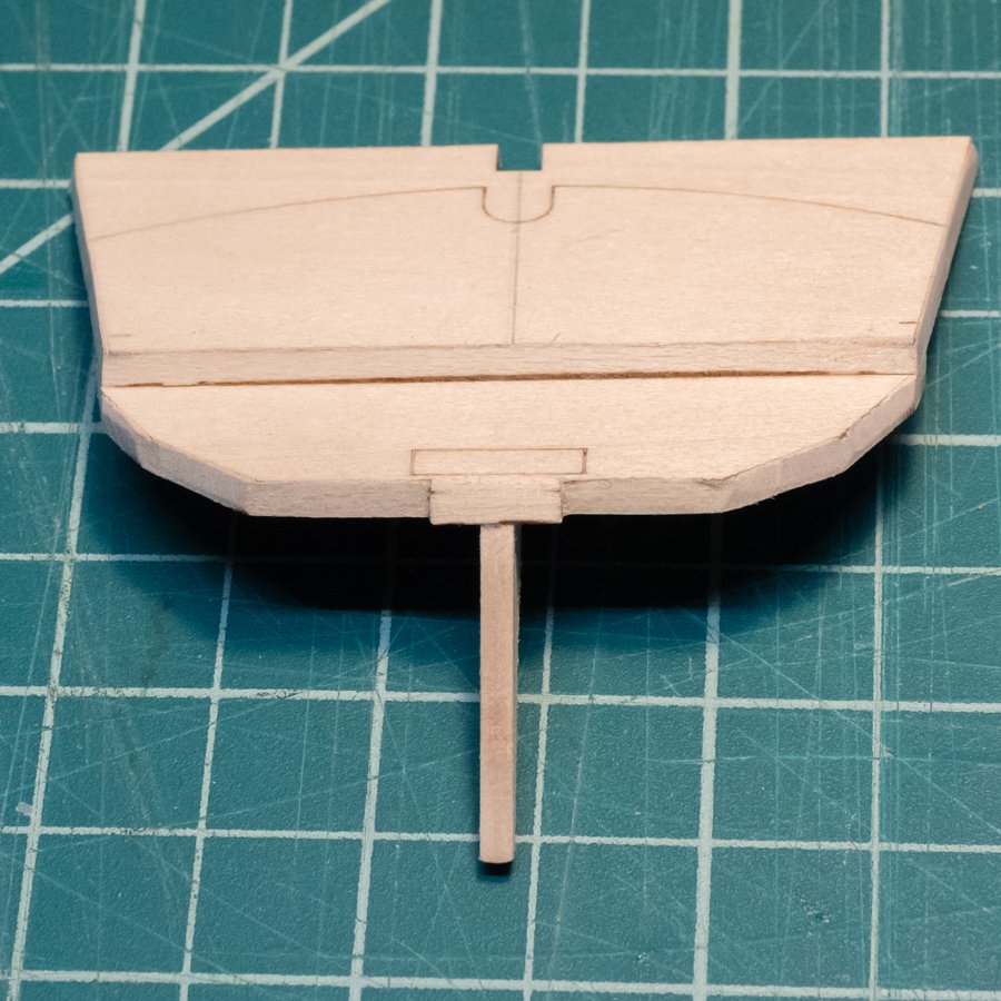
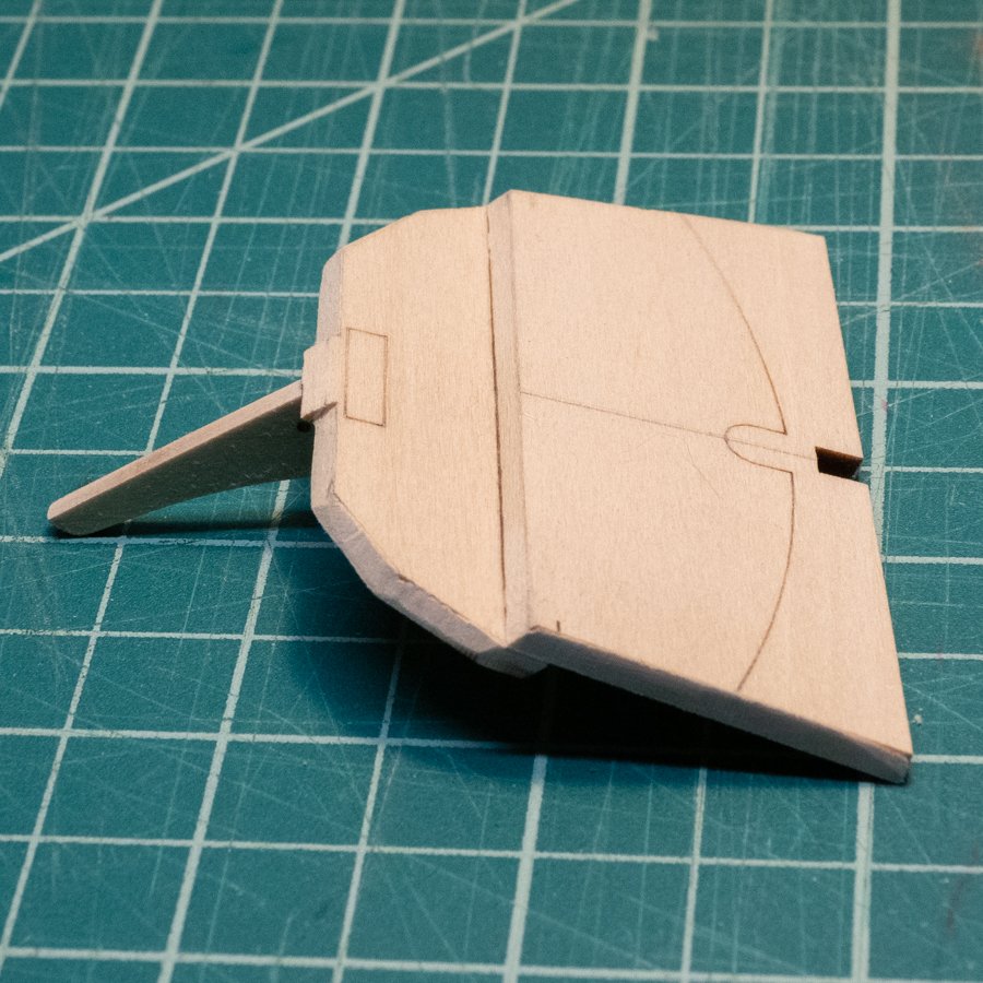
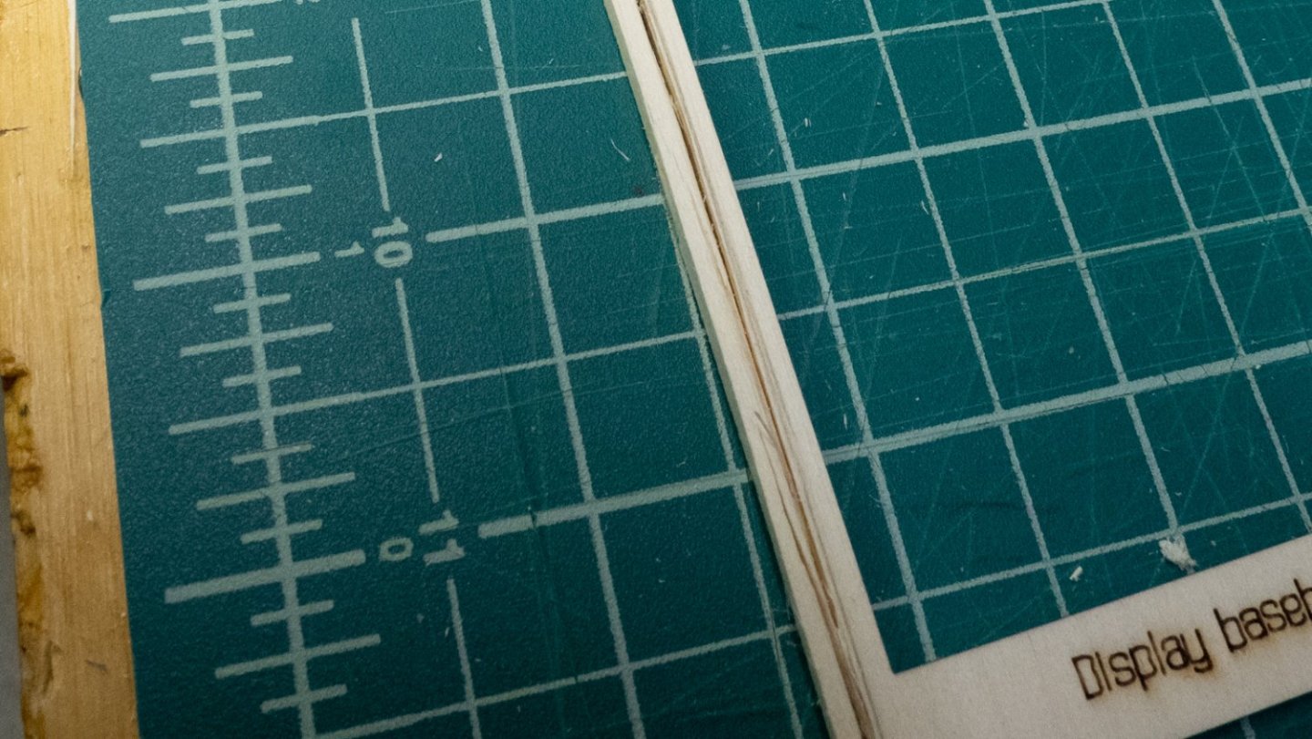
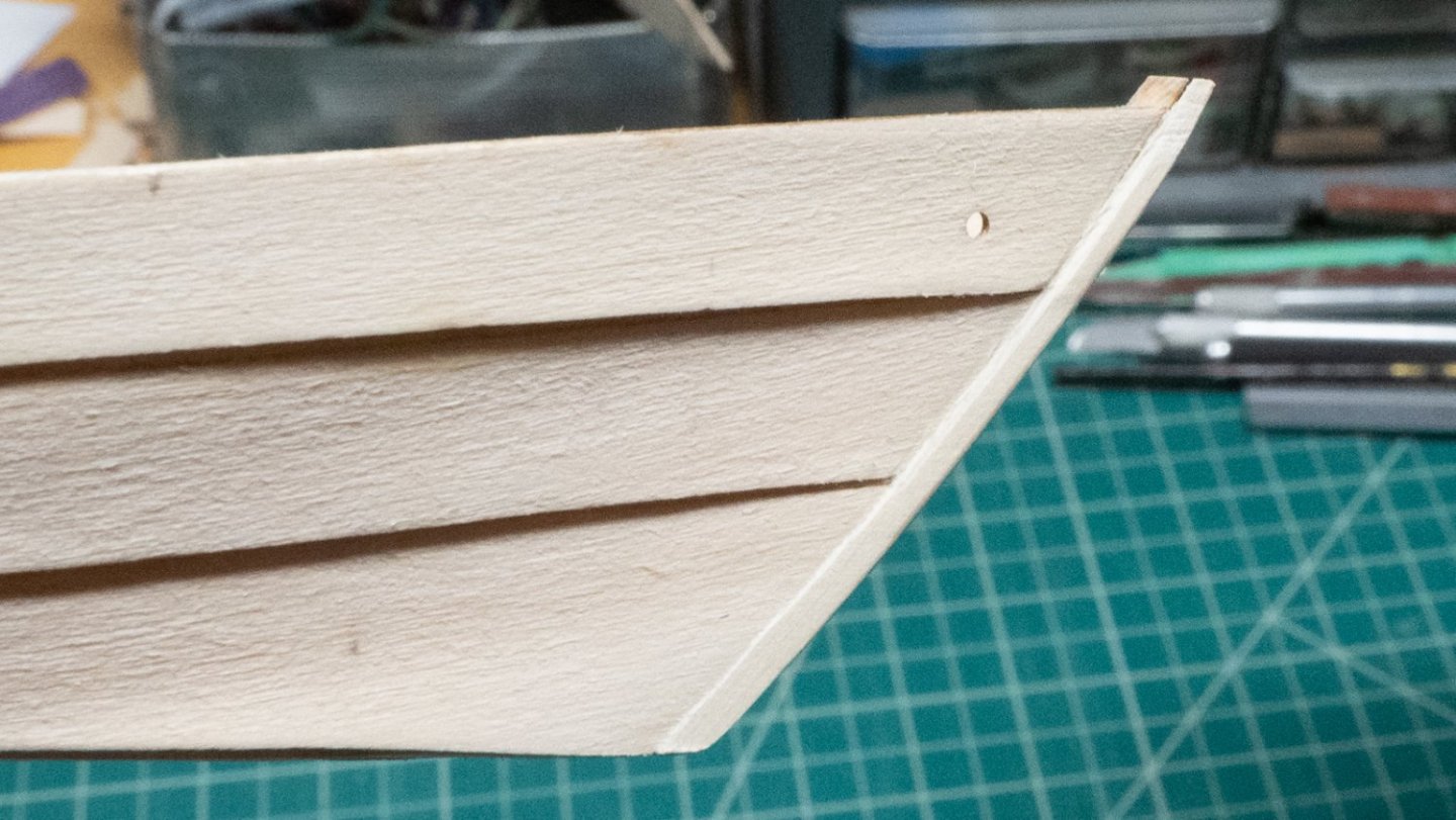
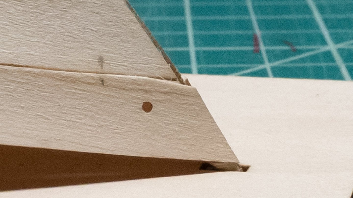
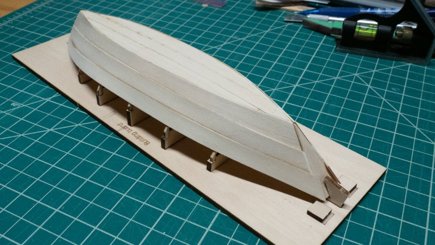
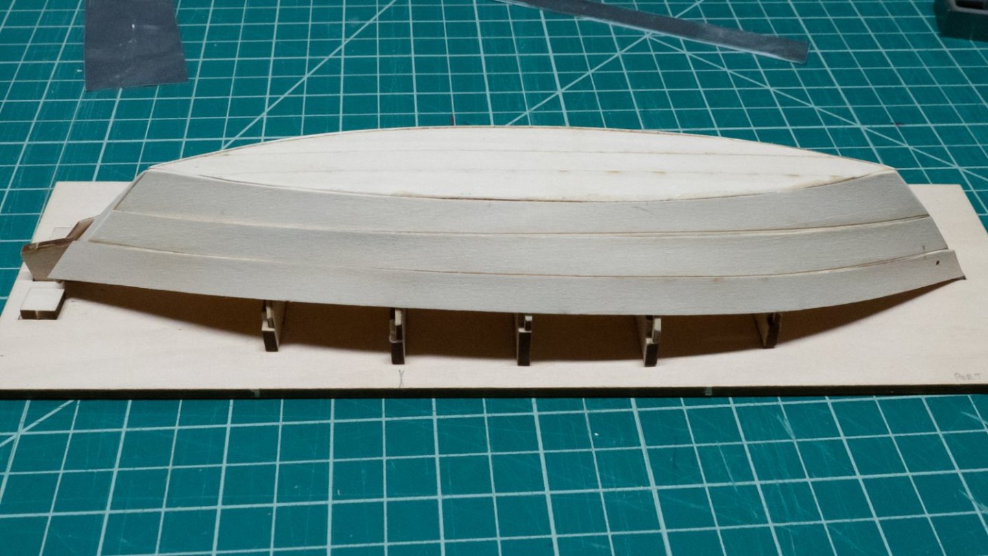
 Everything was going so well, and then I started what would surely be the easiest part of this whole model: putting together the building board. Based on some comments about how the board was a little flimsy, I glued a few cross pieces on the bottom to make it more sturdy. Somehow, this ended up slightly warping the board from end to end. I tried to fix it with some weights and water, and then it warped in a different, unexpected way, then I flattened it out again and it looks better. If I'm lucky, assembling the building board will be the most frustrating part of this build. I made some adjustments to the build board with tape and small strips of wood so both transoms would sit square to the building board; neither was flat against the board as initially assembled. Sanding the the bevels on the bottom planks wasn't hard, it just took some time and care, stopping often to check out the remaining char. I bent the keel and bottom planks on the build board and forms, using hot water to soften them. It took some time to figure out the gluing strategy for the bottom planks - the bow transom moved around a little on its support, and there are three points of gluing that have to be lined up: the planks need to come in centered, glued to the transom while touching, and the bottom of the transom knee needs to be centered and glued. I drew marks on the knee and transom to indicate the centers, and aligned those while gluing. I held the planks, transom, and knee with my fingers while gluing, because it would have been too hard to line up and hold everything perfectly together using rubber bands or clamps. I tried to sight along the center line to make sure the knee was in the right place. When the glue was initially dry, I put a rubber band on to hold it in place for a few hours while it dried. The transom is loosely held in place with rubber bands, and that means some effort is needed to make it line up properly for gluing. The transom knee eventually needs to glue squarely to the keel plank, which means the bottom of the knee needs to be flush with the bottoms of the bottom planks. My strategy was to hold a piece of scrap across the two bottom planks, and press up from underneath with another finger to register the knee flat to the scrap piece, and thus even with the bottom plank surfaces. Holding it this way (I think!) makes the transom meet the bottom planks at the right angle, and sets up the right surfaces for the keel plank. I noticed after inspecting the bottom planks that there isn't a perfect alignment of their surfaces with the rectangular transom cut-out that the keel plank is glued to - the cut-out was too shallow. Some options: Put a very thin piece of wood in there to build it up, then do the same to the knee so that everything continues to be level and straight Unglue it and sand down the transom more to create the appropriate shoulder. Step 2, but don't take as much off. Then, sand the bottom planks a little to try to bring them in line with the shoulder. Plan to use filler. I chose option 1. I sanded down some very thin basswood strips with a sanding stick, then cut them to size to cover the necessary parts. After gluing those in place, I re-glued the bottom planks, holding them the same way as before. This looks a lot better, and should help avoid filler later.
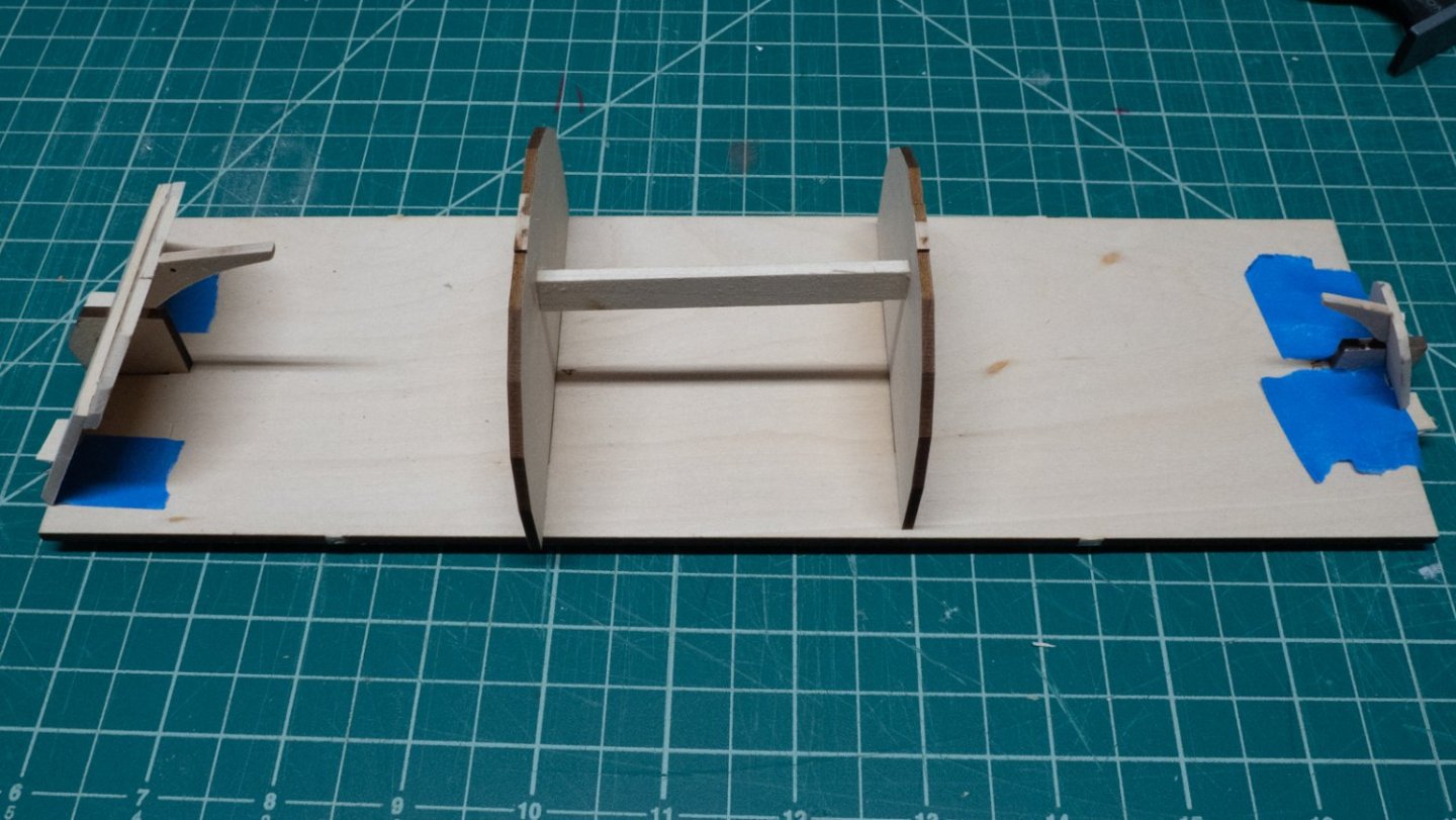

-
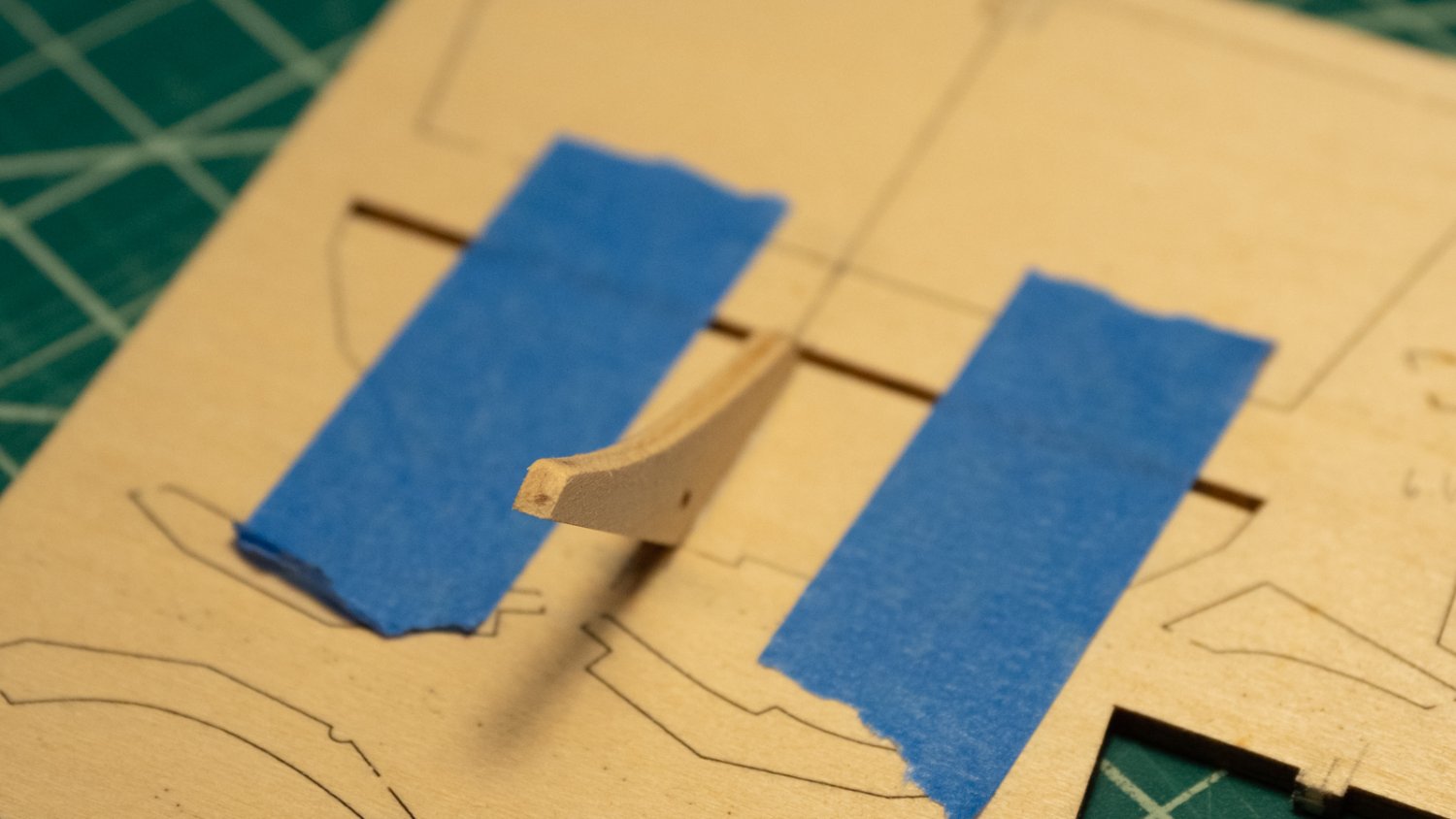
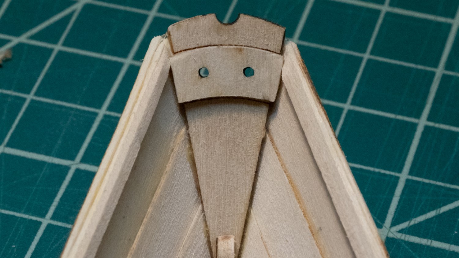
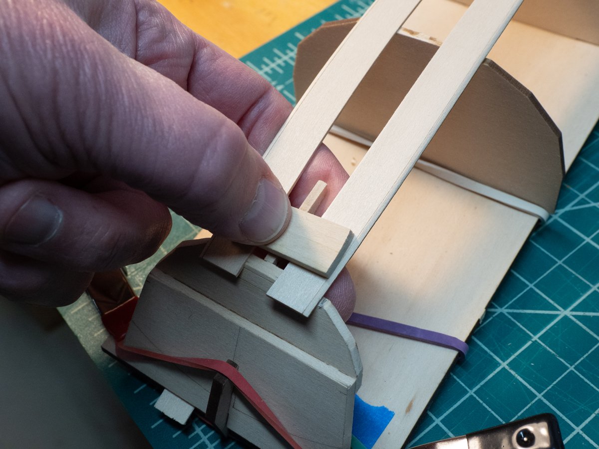
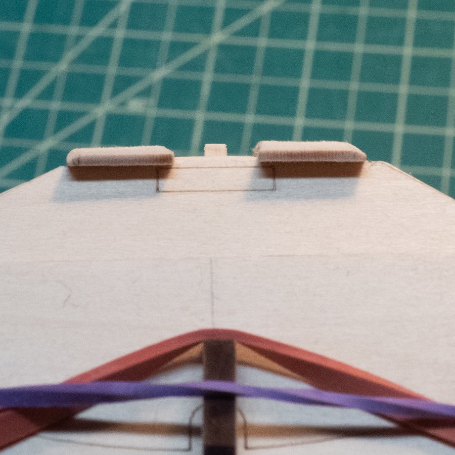
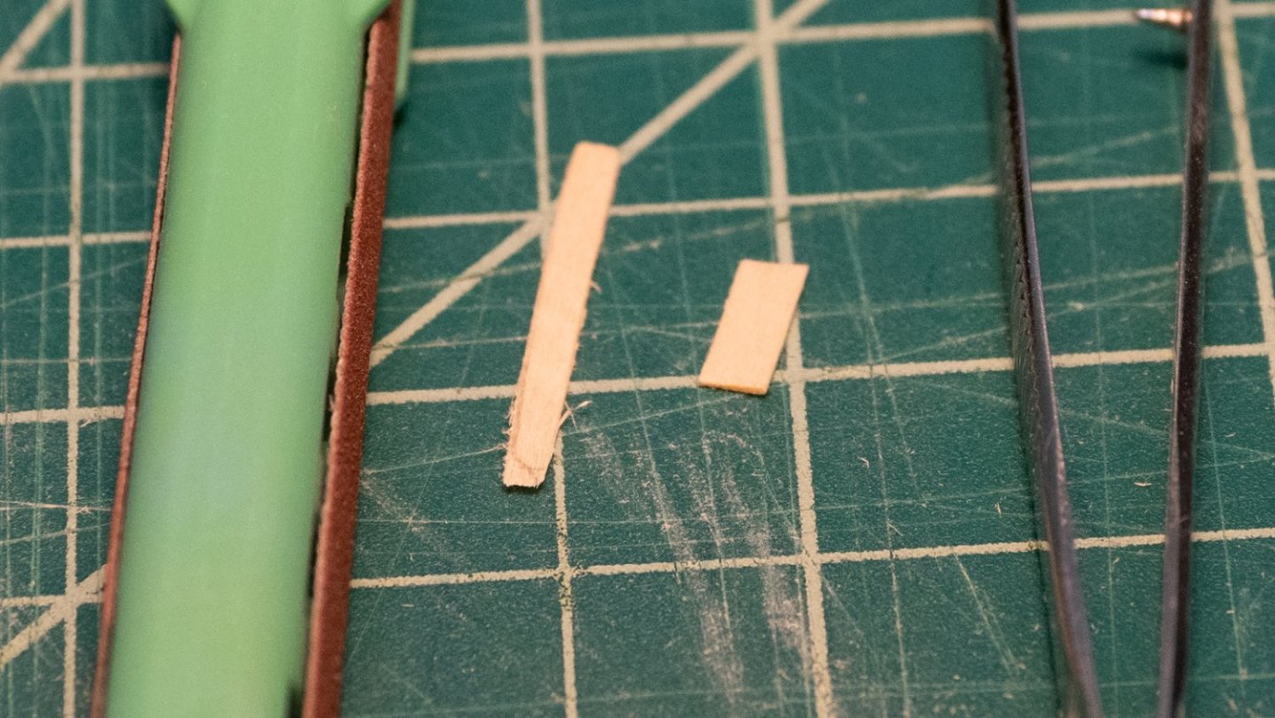
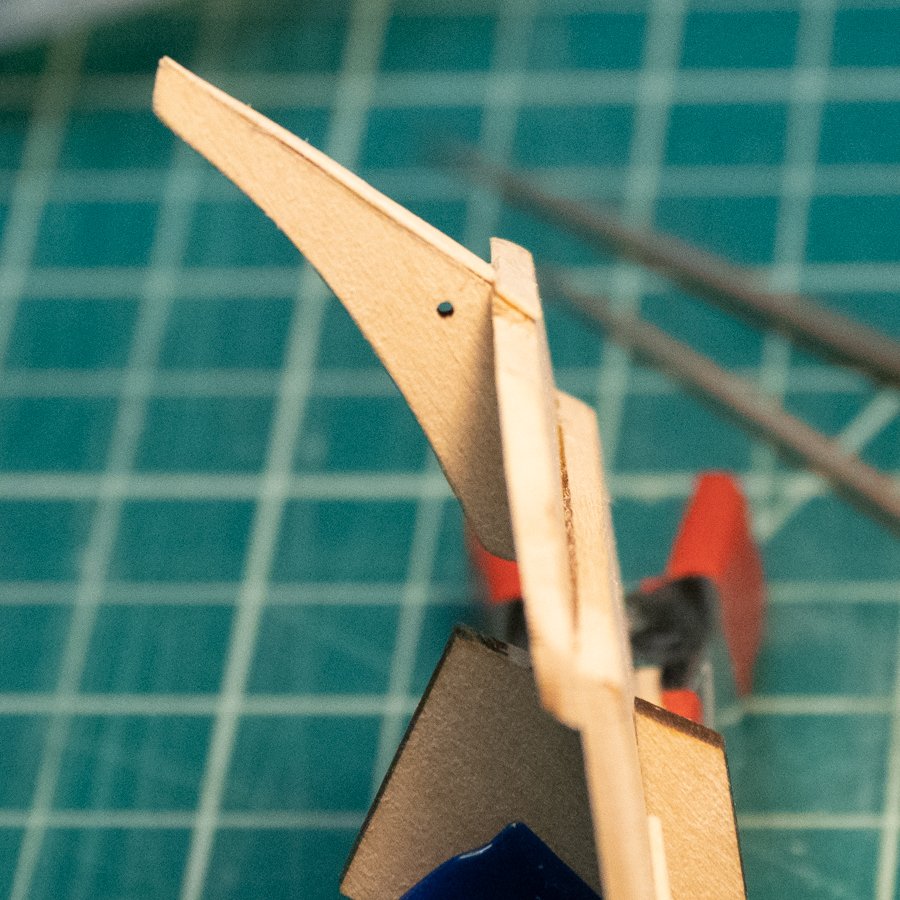
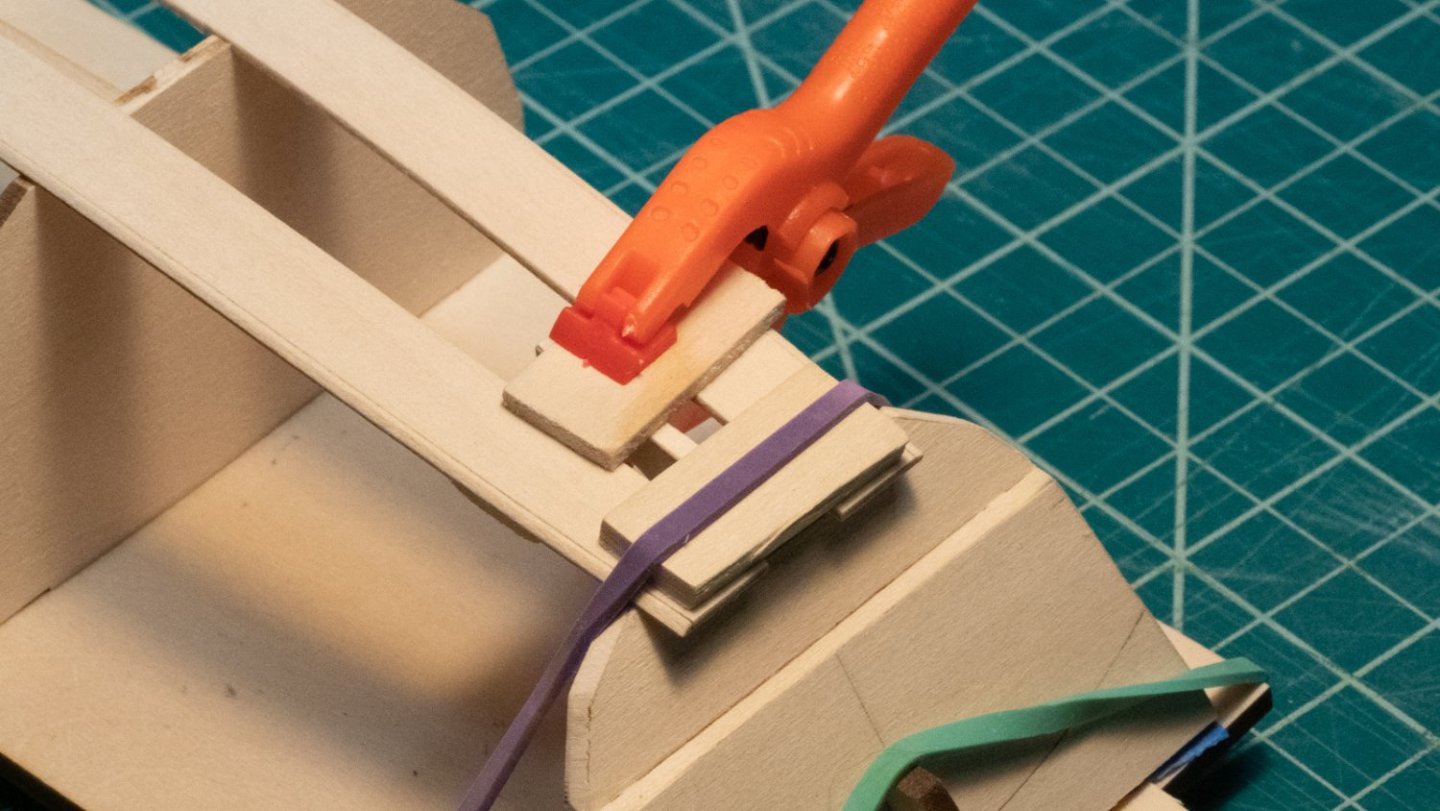
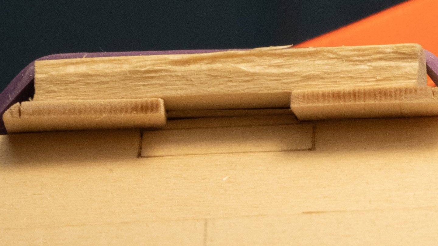
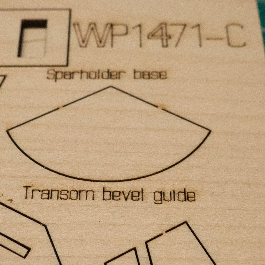
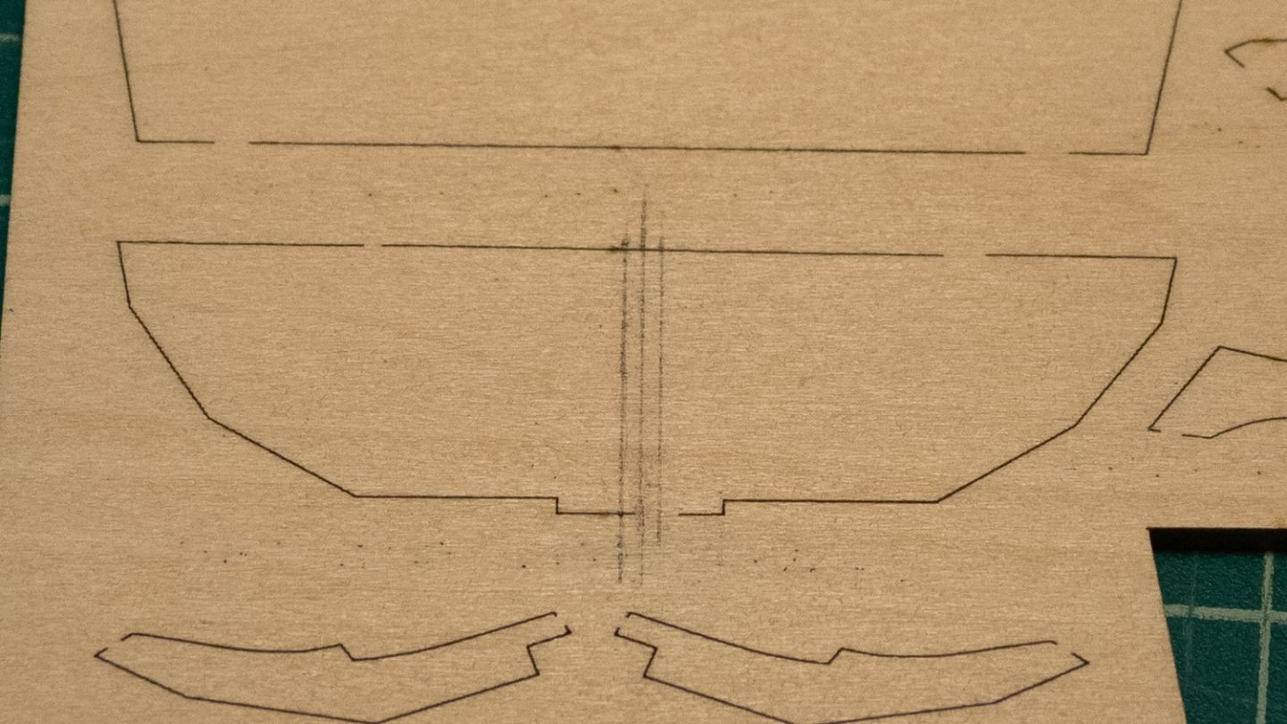
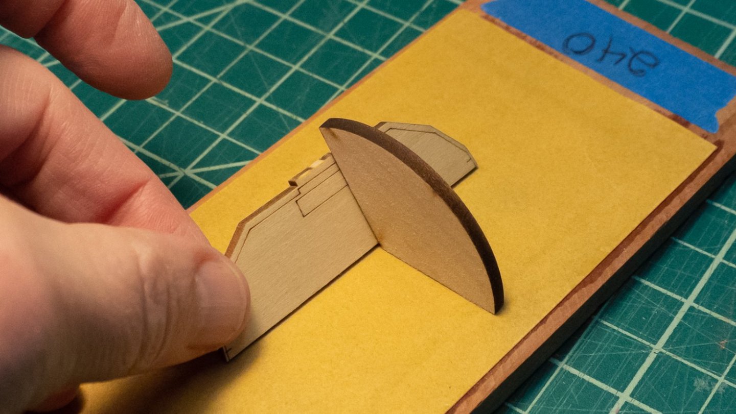
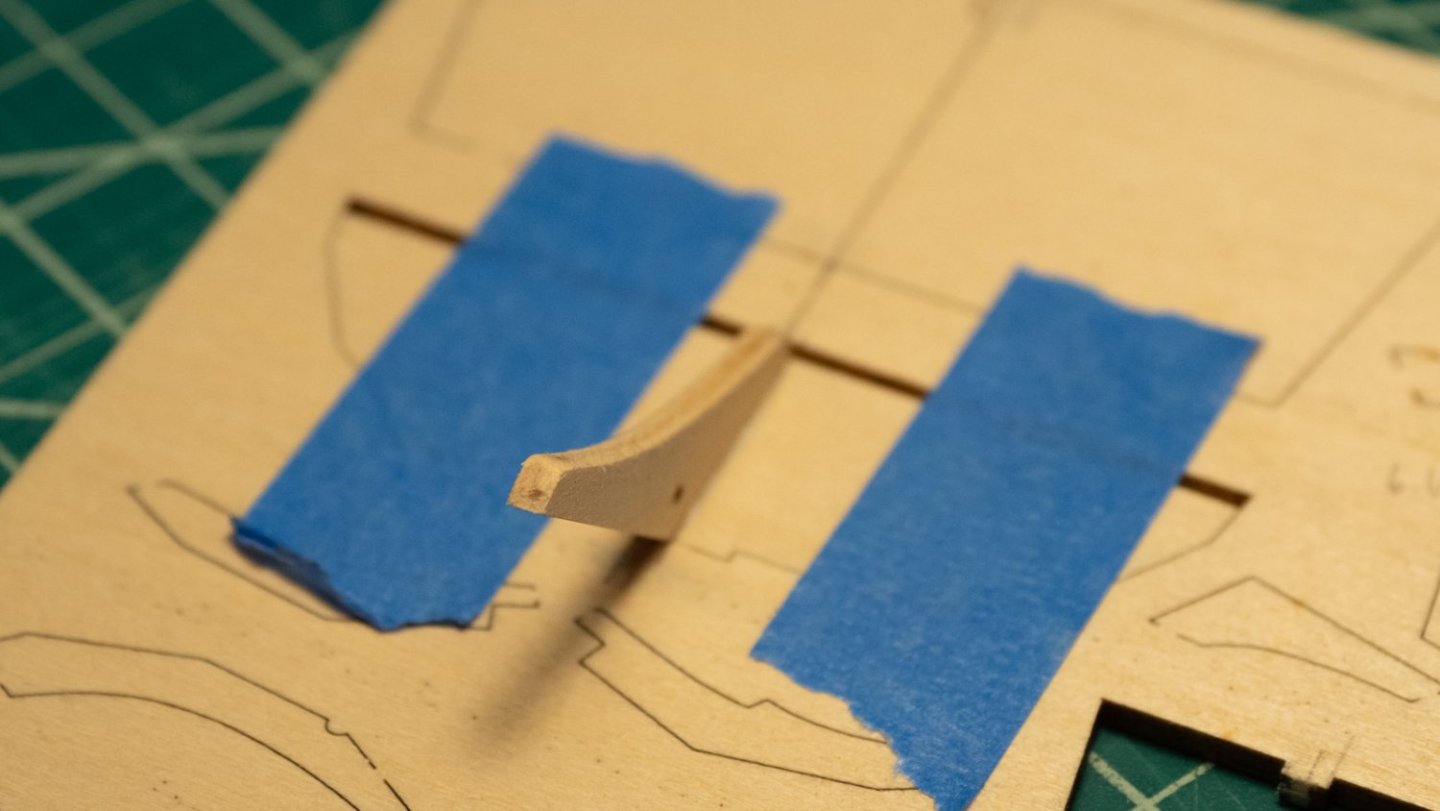
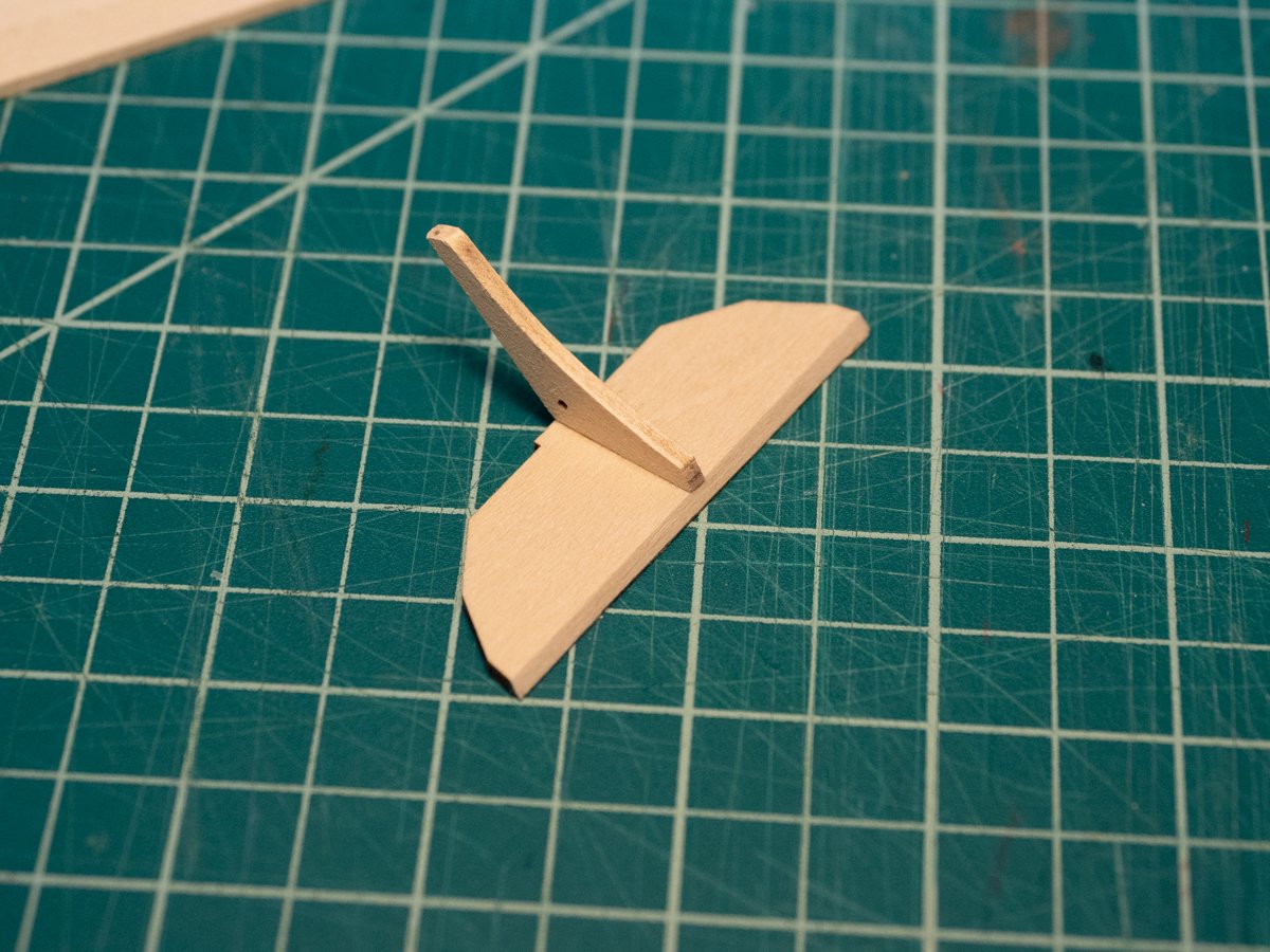
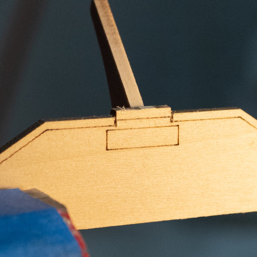
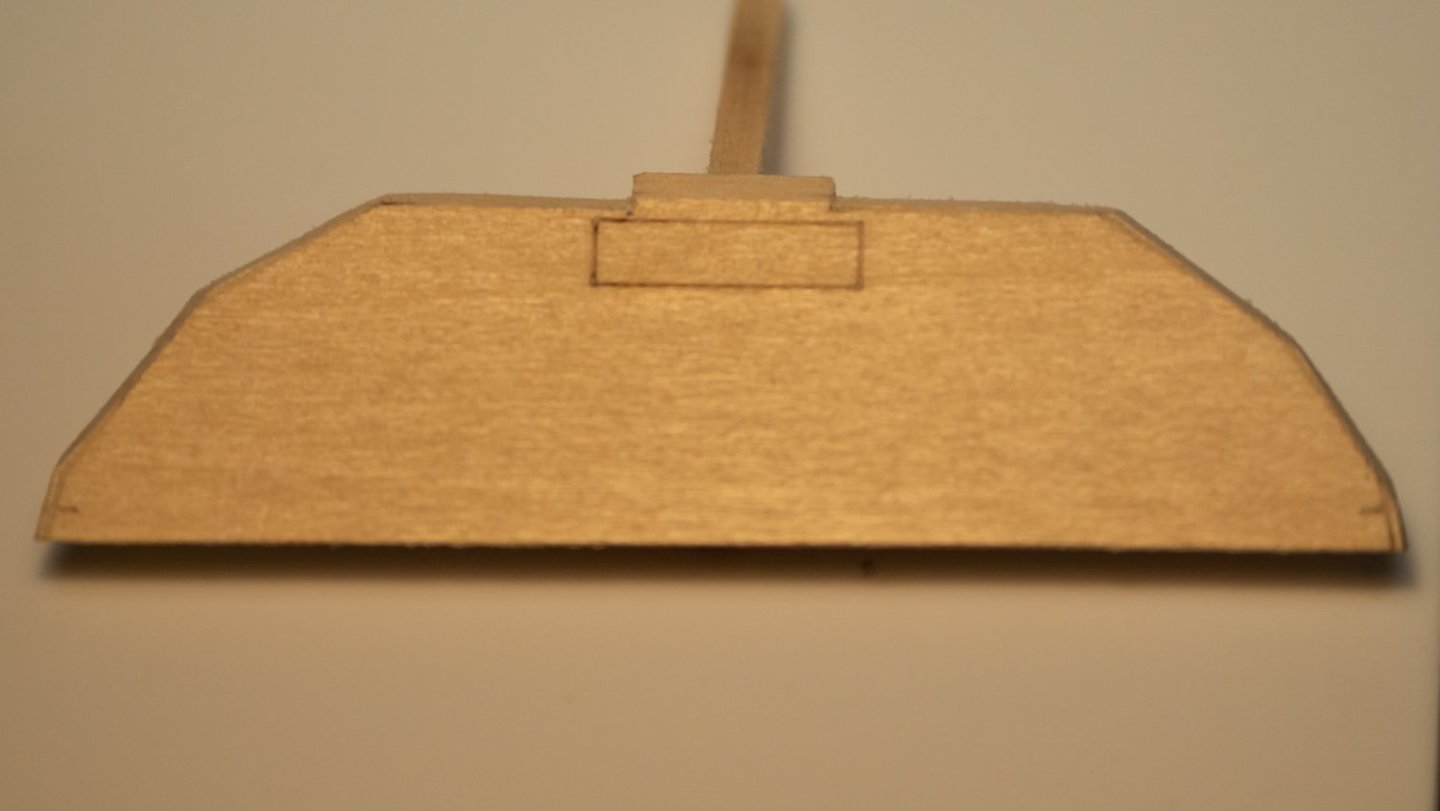
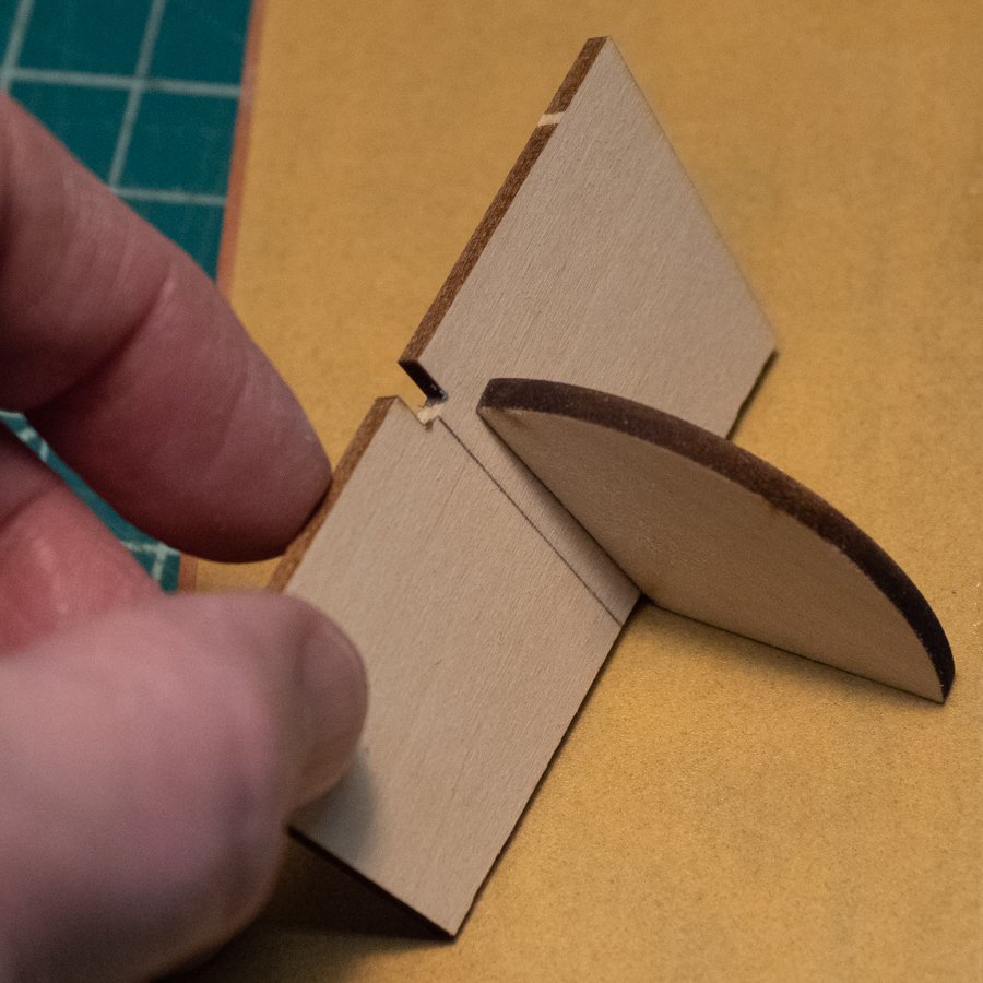
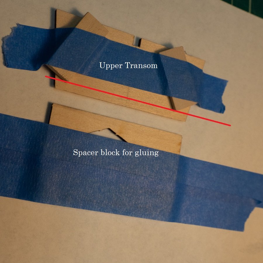
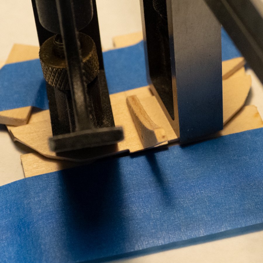
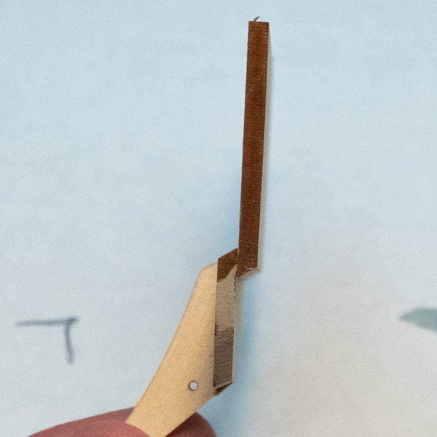
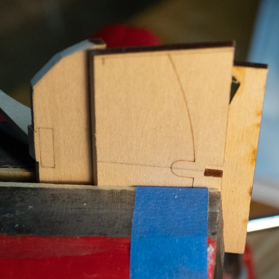
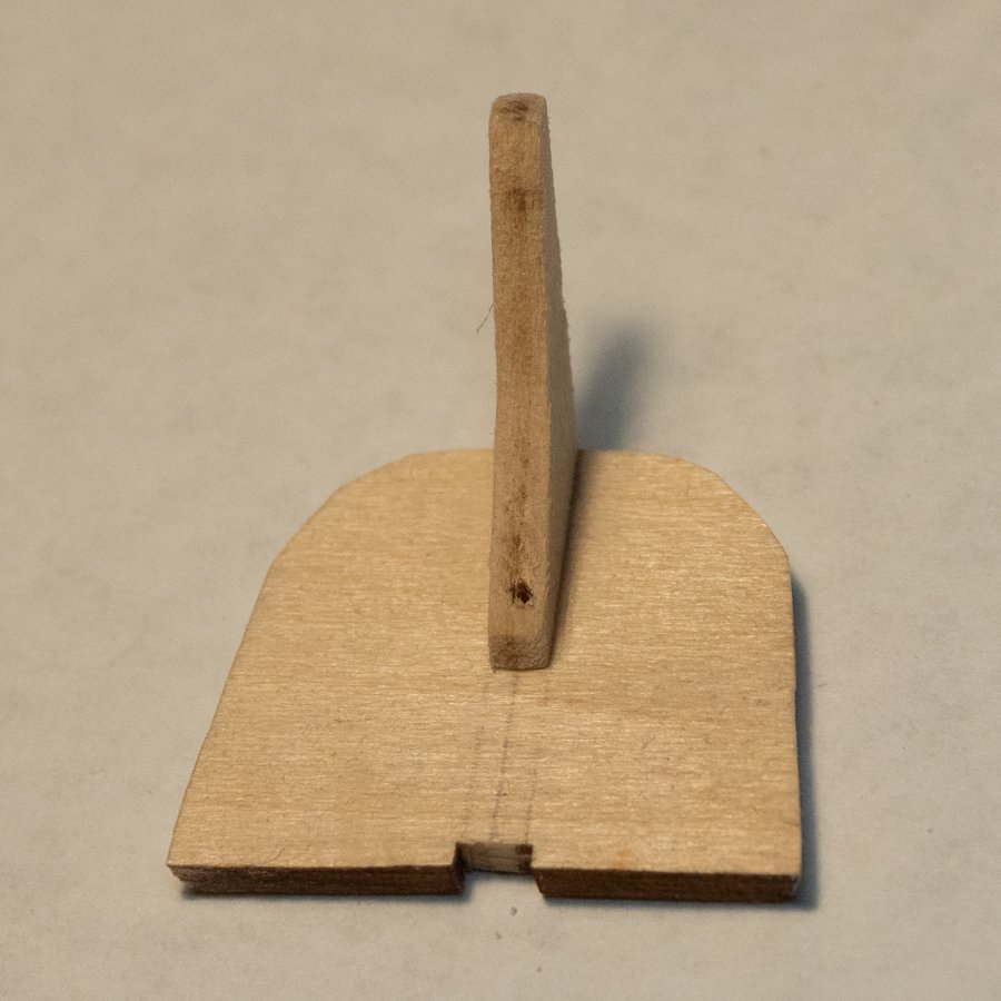
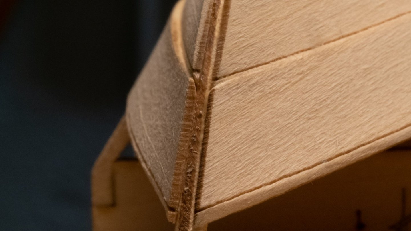
With all the bow transom steps complete, the stern transom now has my full attention. There are two parts for the stern transom, and I followed instructions for the lower one first so I could keep the instructions straight. The back and forth between the 2 assemblies was confusing for me to follow. Starting with the lower stern transom... I read ahead in the instructions, and there were going to be some center lines and knee-alignment lines coming, and I drew those before removing the pieces from the building board. To bevel the long edge, the instructions say to use the supplied bevel guide; it took me a while to figure out that it's in one of the parts boards. For sanding with the bevel guide, I believe the instructions for the lower stern transom are incorrect: the lower stern transom instructions say to sand with the "bevel marks facing away from you". The picture shows the bevel marks facing towards the builder during sanding, and that is correct. I think the skipping between the three transom pieces may have confused the author himself; the other stern transom piece is sanded with the bevel marks facing away, so I think this instruction should be included with it. Hold the guide down flat and firmly, and move the transom piece back and forth on the sandpaper, while maintaining contact with the bevel guide. Once the char is gone, you're done. I cut out the stern transom knee, and sanded its edges flat. I put the lower stern transom piece back into the parts board, and glued the knee, using the pencil lines as guides. The picture of this below is not very good, but it's like the one from the bow transom assembly. Before sanding the bevels, make angled cuts as pictured - the intention here is to create a "shoulder", and the cut should be at the angle you're beveling. (Thanks to Zack Soderquist for pointing that out.) It took about three light passes with an x-acto razor saw blade, not much work. [Edit: The next few steps are better detailed in this future build log post.] Instructions say to sand the bevels "except for the outermost ones". Consulting other build logs, and reading ahead in the instructions, this means to not sand a bevel where the upper transom piece is glued (the last 1/8" of markings) but to bevel everything else. One side came better than the other, although it's hard to tell in the picture below. Now that the lower transom piece is complete, I moved to the upper transom. After drawing the center lines with the piece still in the parts board, I sanded the bevel using the bevel guide. Pay attention to the picture in the instructions and sand the correct way. Gluing: I made a gluing jig so that everything would rest flat. I taped the upper transom piece printed-side down. I taped two small pieces of wood on top of the upper transom with their "points" at 1/8" from the edge. I used those pieces as stops at 1/8" so the overlap would be even and I wouldn't have to guess during glue-up. There's a piece of scrap from the Dory model that is under the lower transom piece to keep it flat against the upper transom while gluing. I put some glue on the upper transom, and put the lower transom onto the glue, registering its long edge with the stop blocks. I made sure the center lines for both pieces were aligned, and put some light weights on. Now that the parts have been glued, the next step is to bevel to the lines on the upper transom, which will also touch the "top" of the lower transom. In one orientation in the vise, I used a scrap piece of wood from the earlier gluing jig to assist the vise and not damage the transom assembly. The building board is next...
.jpg.9c86f5762f14f55e3f6e0ed3ed3df580.jpg)
.jpg.913799881627abfb767ccc9c16d08529.jpg)
-
@Keith Black I'm in Ann Arbor currently...
-
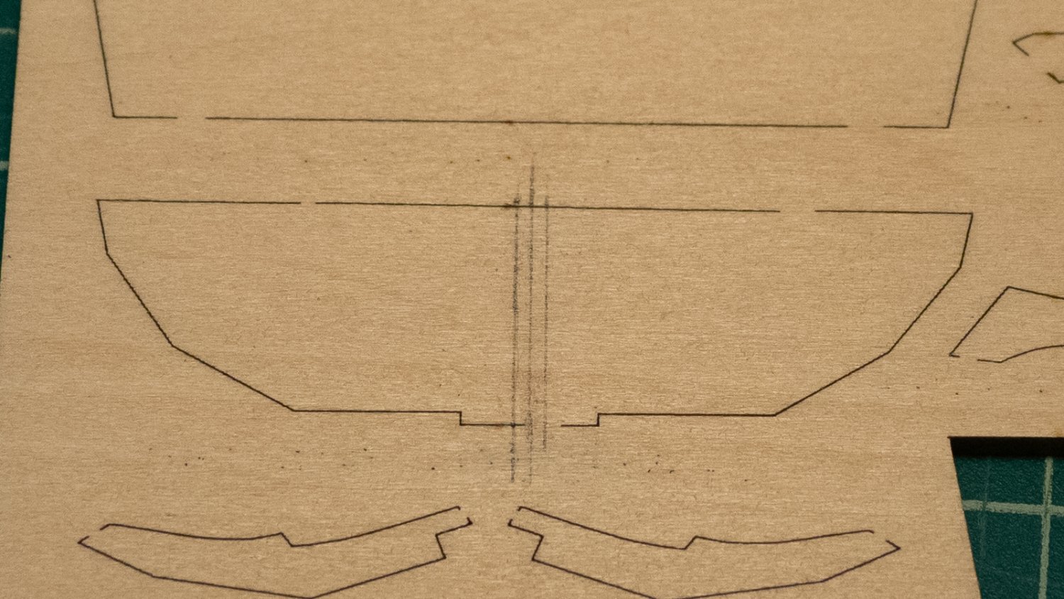
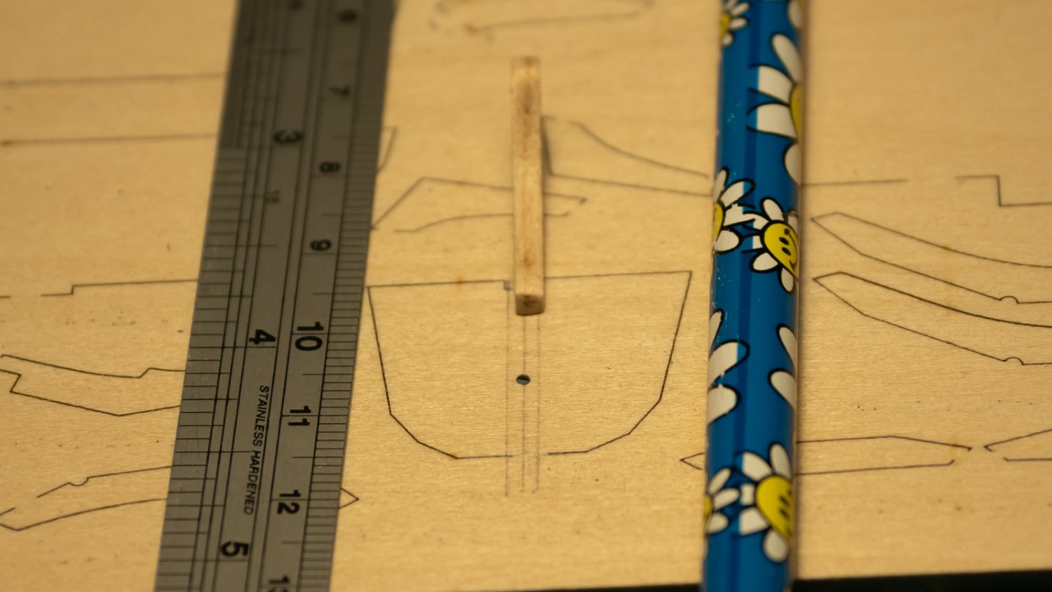
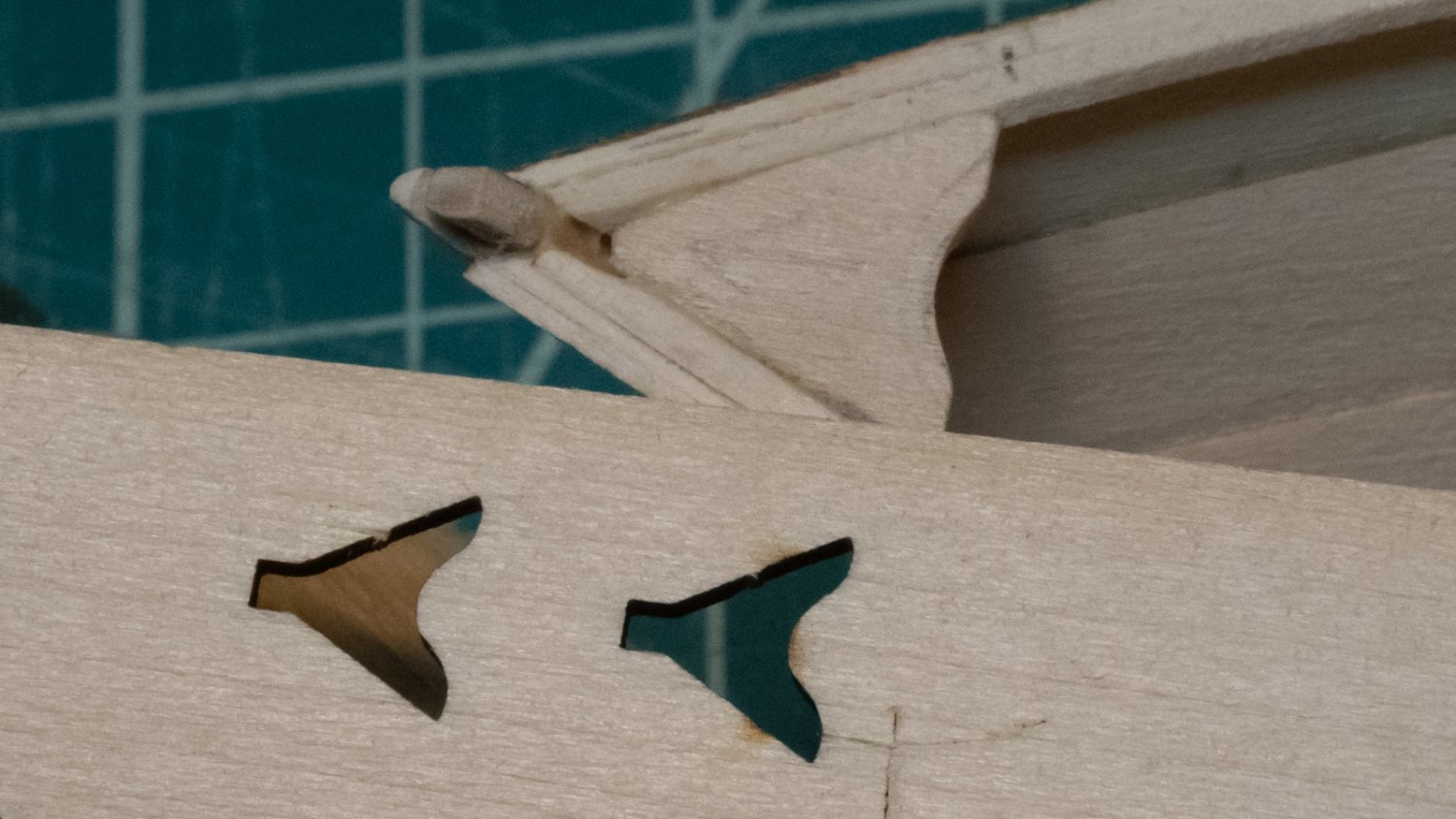
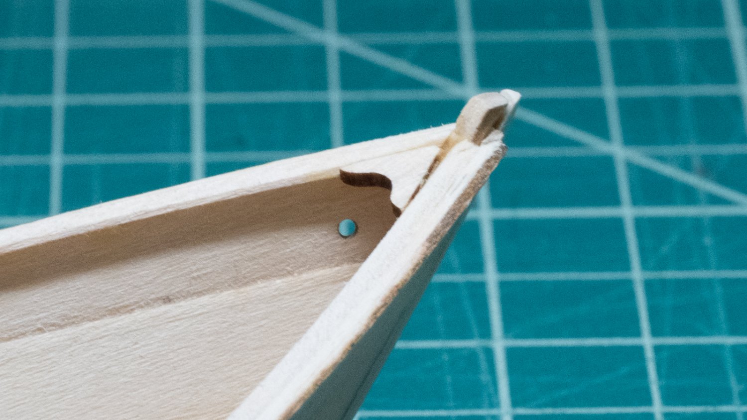
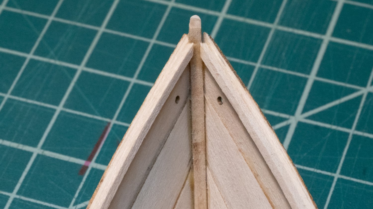
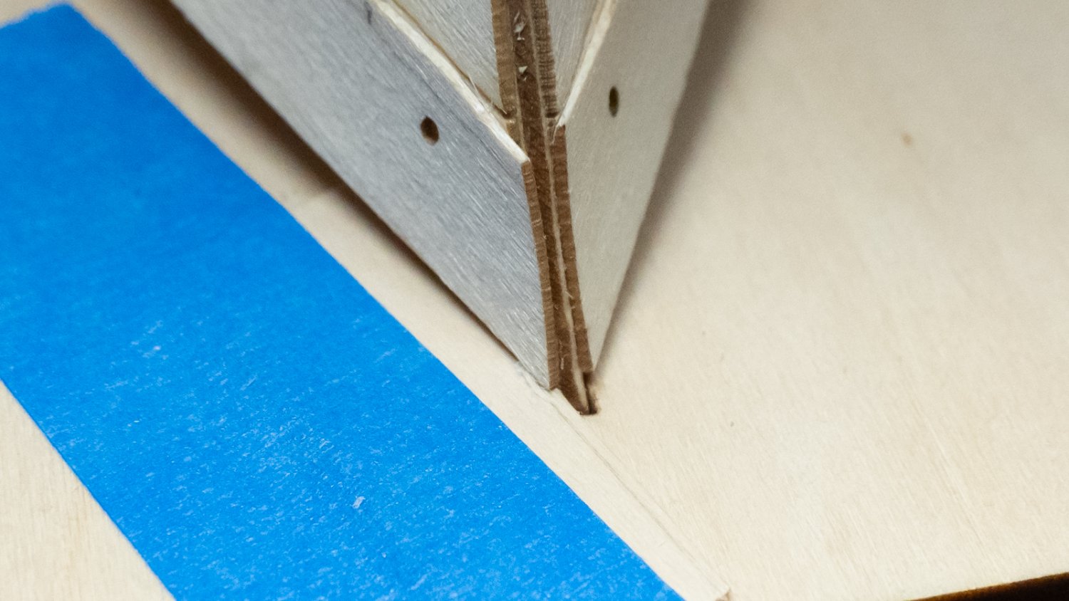
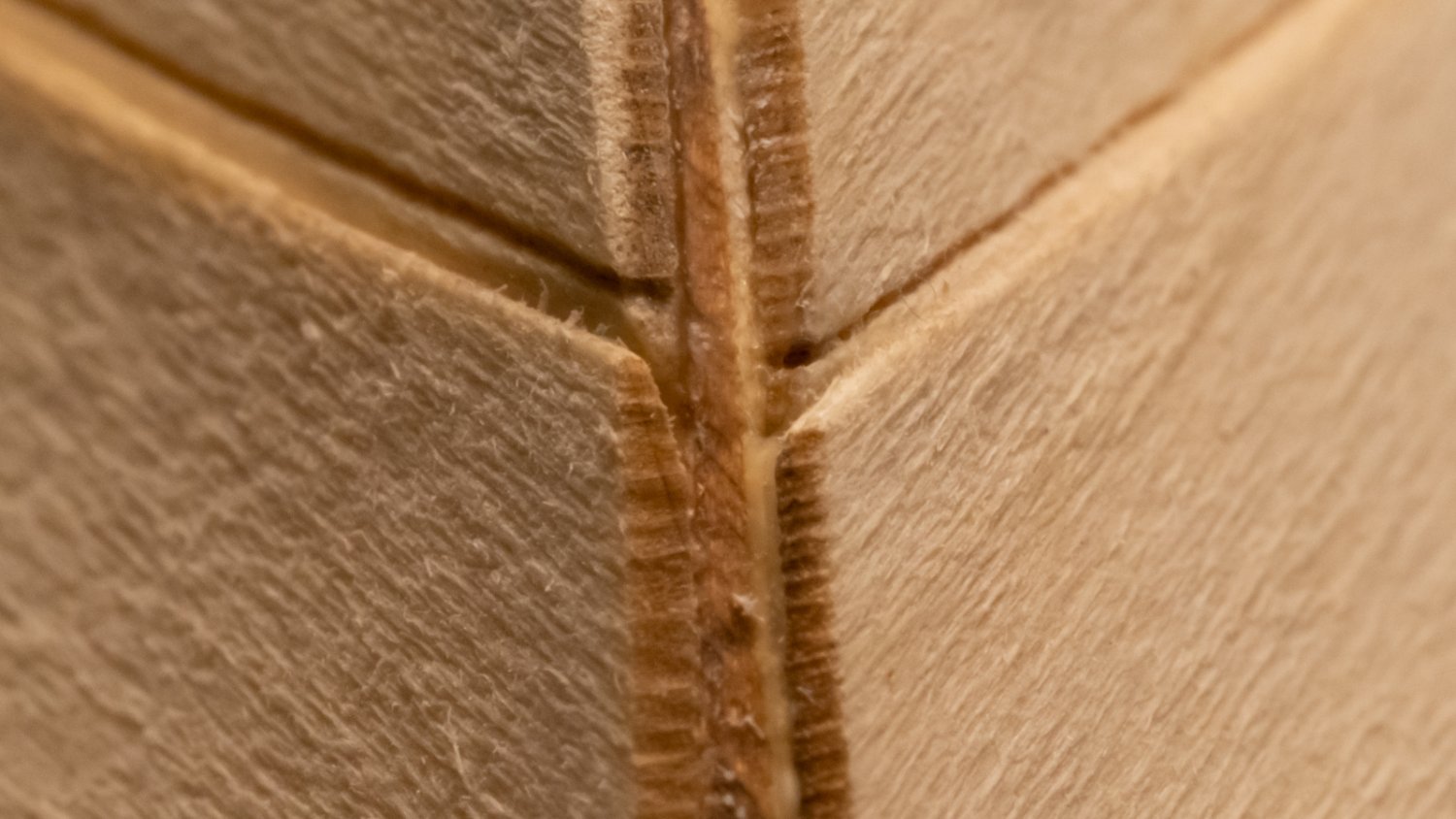
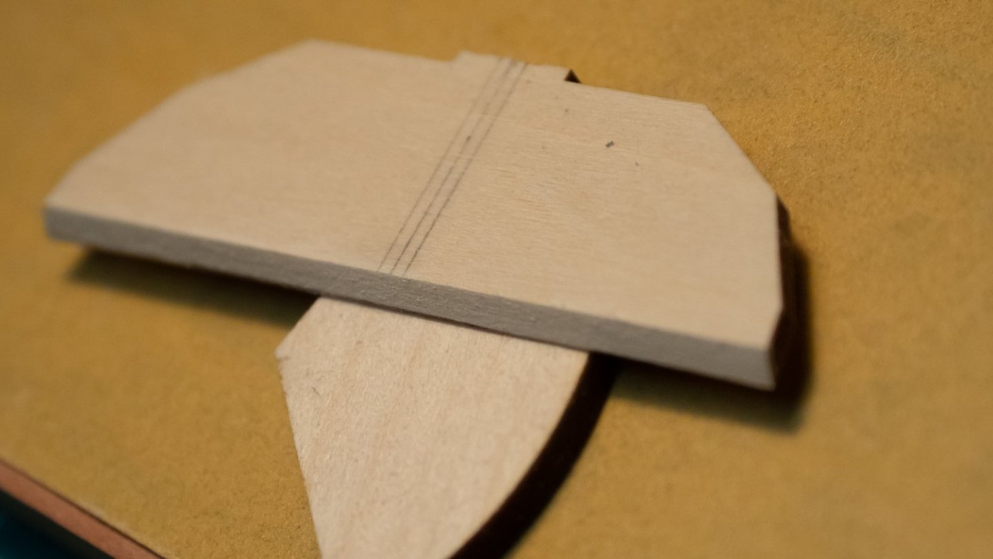
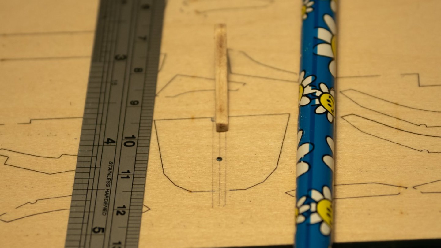
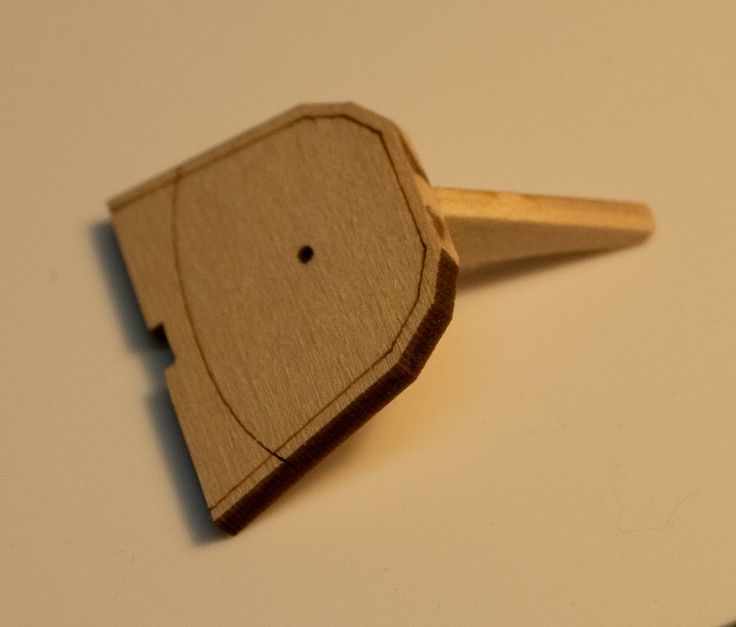
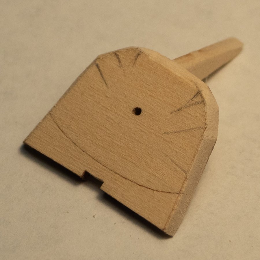
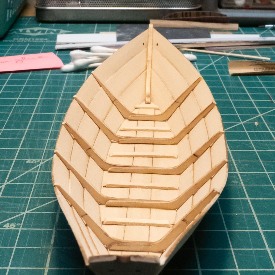
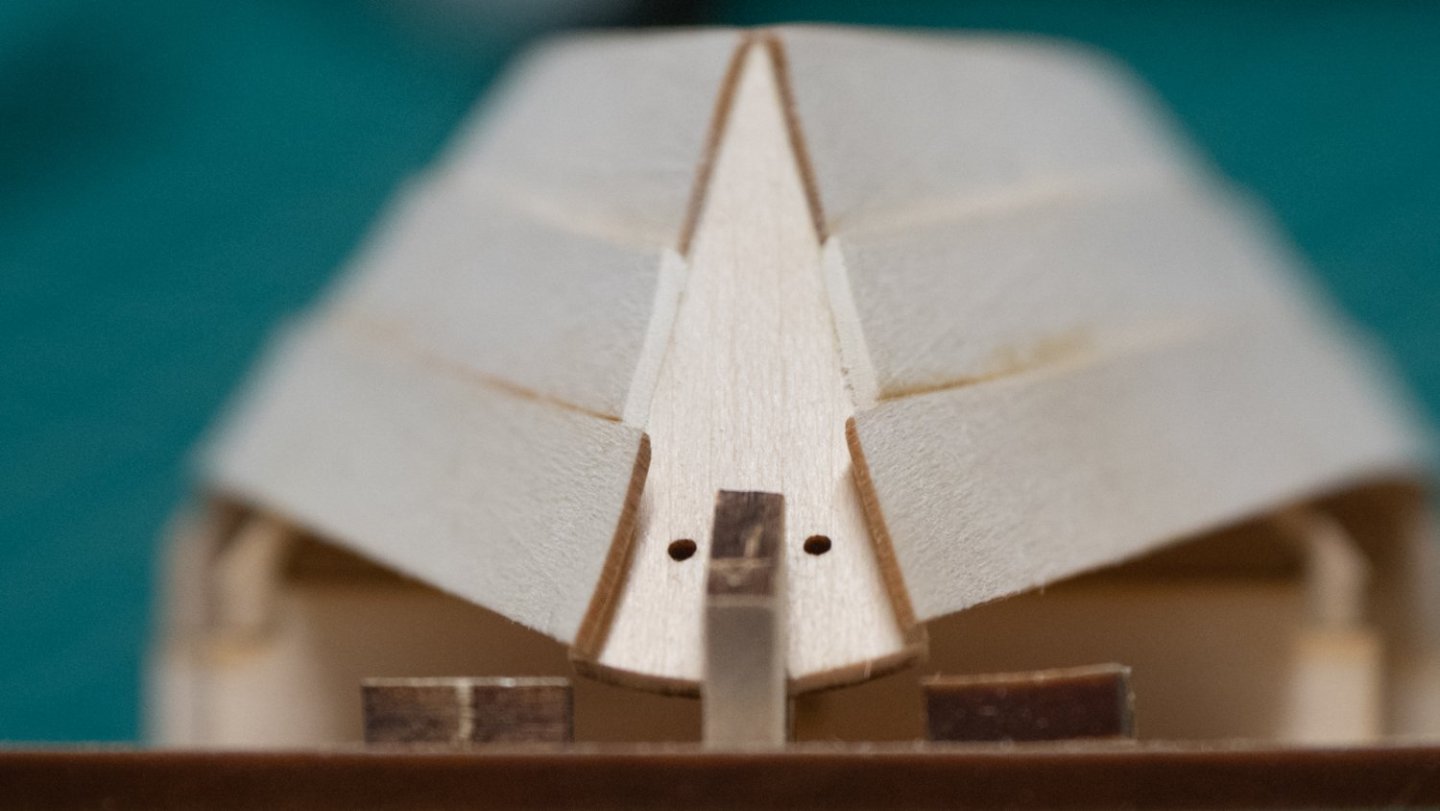
Here we go with the Norwegian Pram by Model Shipways. The first several steps cover both the bow and stern transoms and knees, and go back and forth between the two. I am going to do one transom at a time so I can keep my parts straight, bow first. I cut out the knee and sanded off the char. Then I cut out the bow transom from the parts board and sanded/filed the necessary spots. The next step was to draw a midline, then draw two more lines the width of the knee apart. After struggling with the small transom and a pencil and a ruler, I realized that it would be a lot easier to draw these lines onto the transom while it was still in the parts board. I tried this with the spare transom, and it worked great. It's helpful to extended the lines past the laser lines to use them as sight lines when gluing the knee. After drawing the lines, I cut the transom out of the board, sanded the extra "connection" bits, then put it back in the board. I glued the knee to the transom, using the extended lines on the parts board to line it up. The picture in the instructions show the appearance of the knee when it's glued, and that indicates which of the "legs" of the knee to glue to the transom (the shorter one). Ignoring the stern transom instructions, I went to step 3, finishing the bow transom. Bevel each facet as flat as possible, removing the char, and using the far edge and the marked bevel line as your guides. I took a little too much off where the knee meets the transom, but the rest looks pretty good. I found it hard to make the straight-ish lines of the contour as shown in the instructions. Drilling the hole through the transom and the knee: my pin vise drill bits aren't marked (which one is #55?), so I selected the one that fit in the hole in the transom. I put tape around the knee to help prevent tear-out, after seeing in another build log that tear-out was a potential issue. I went really slowly, and it came out pretty well, although the hole is just a touch off center in the knee. Next: returning to the start of the instructions to follow the stern transom steps.

-
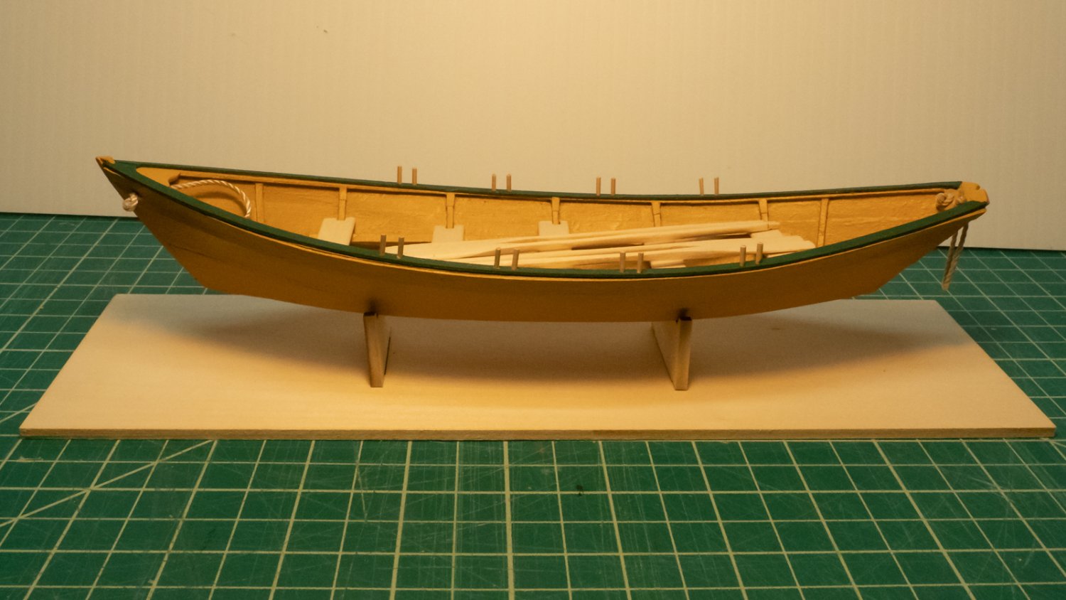
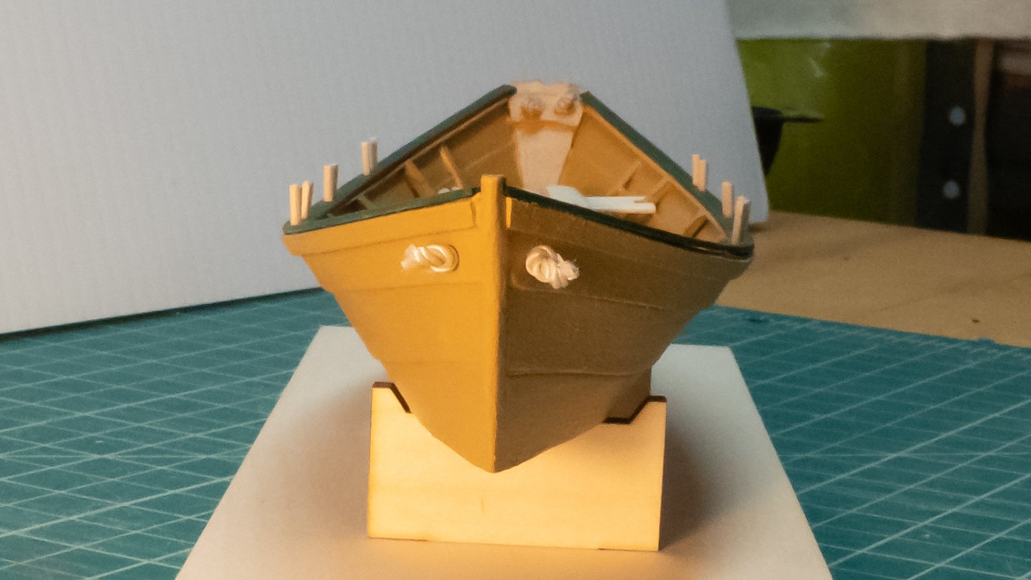
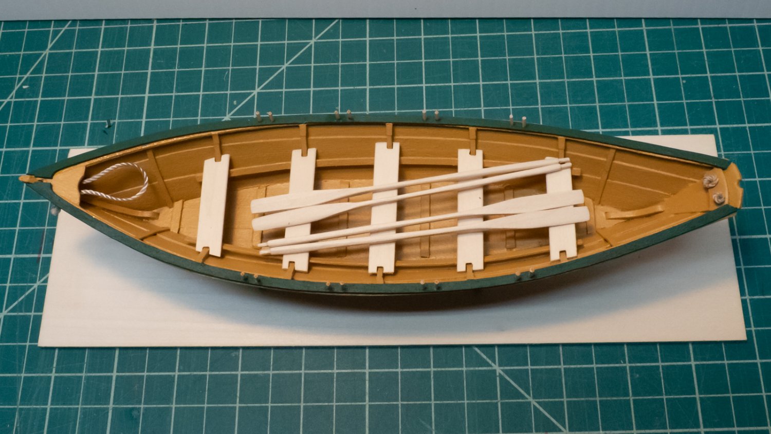
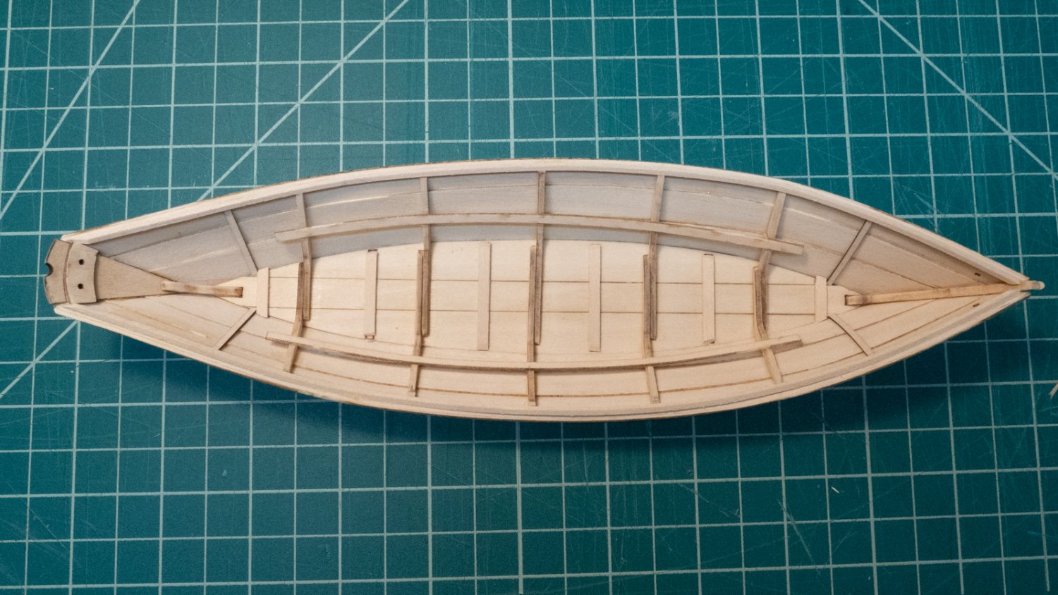
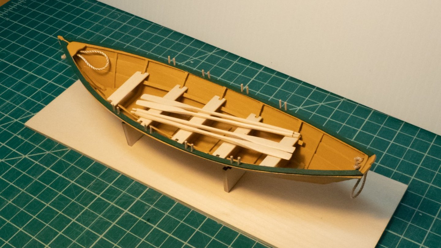
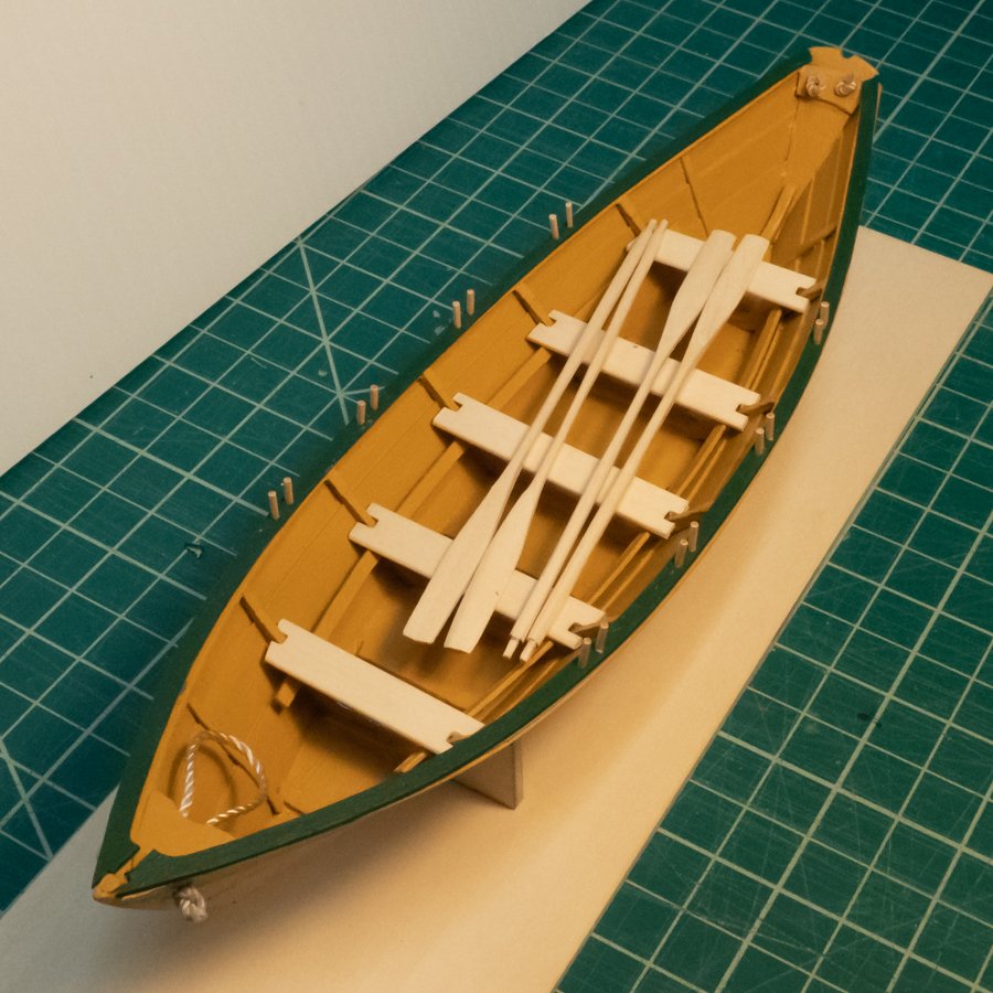
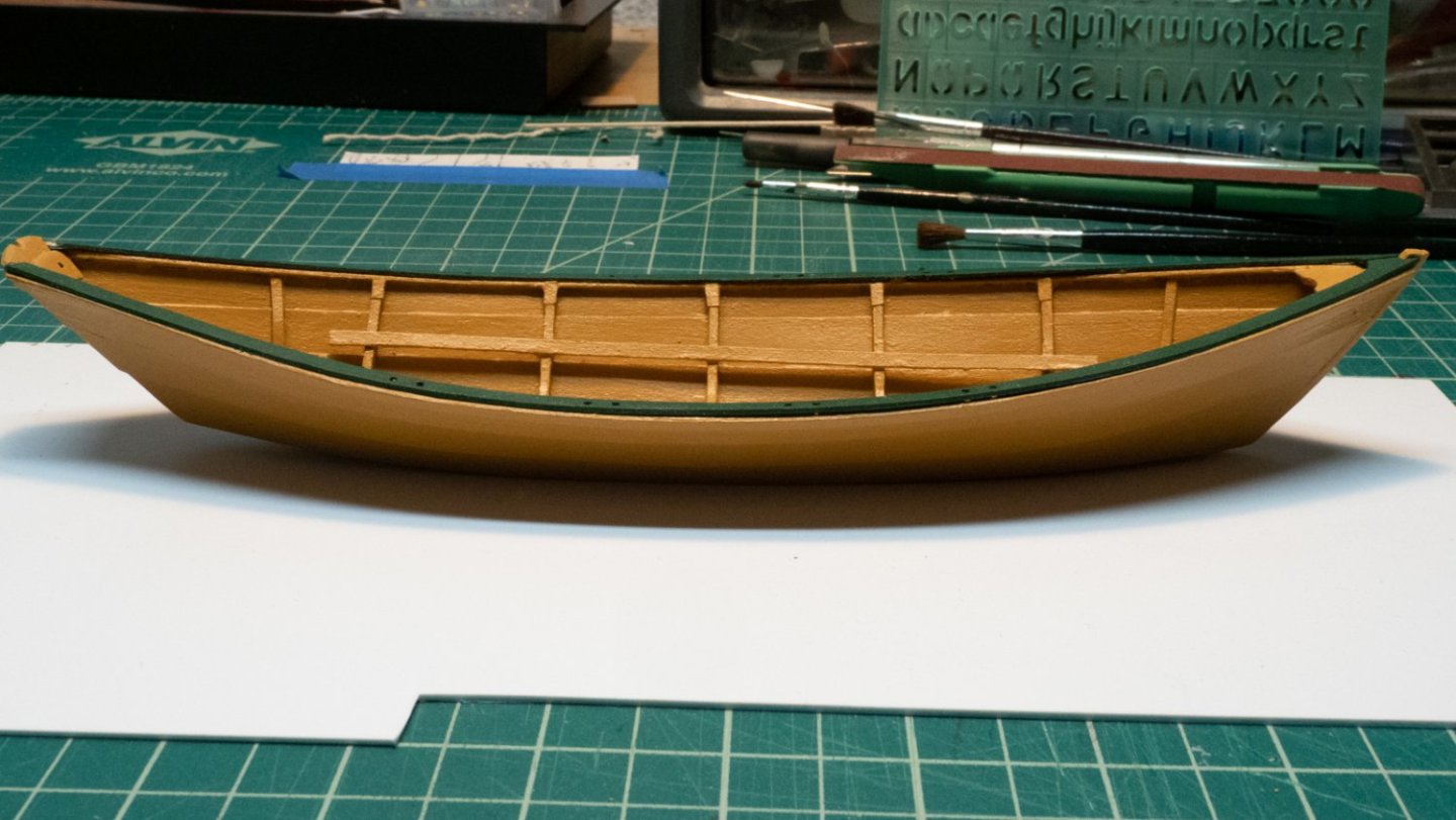
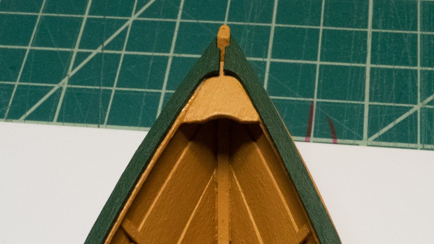
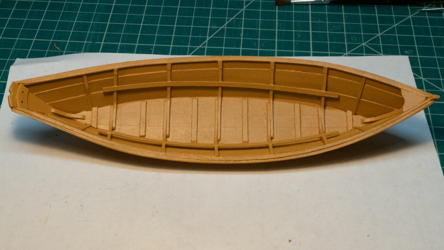
Some pictures of the completed dory...


- 40 replies
-
- 9
-

-
- Lowell Grand Banks Dory
- Model Shipways
- (and 1 more)
-
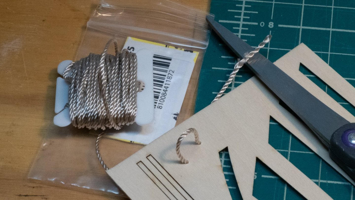
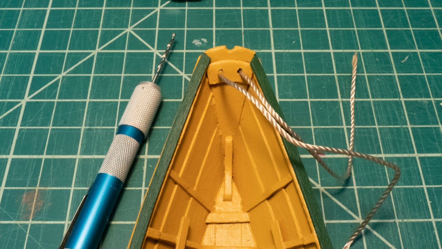
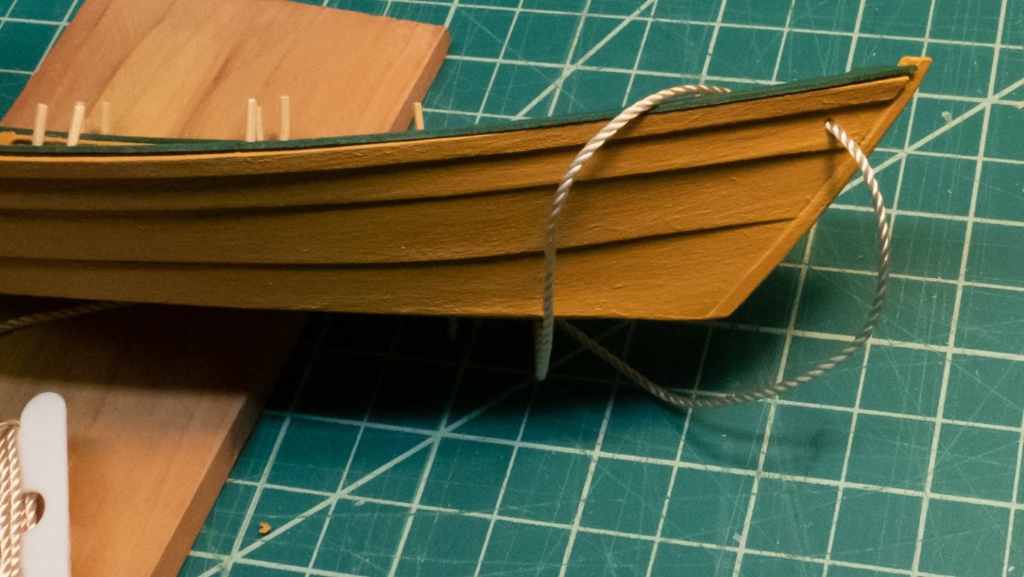
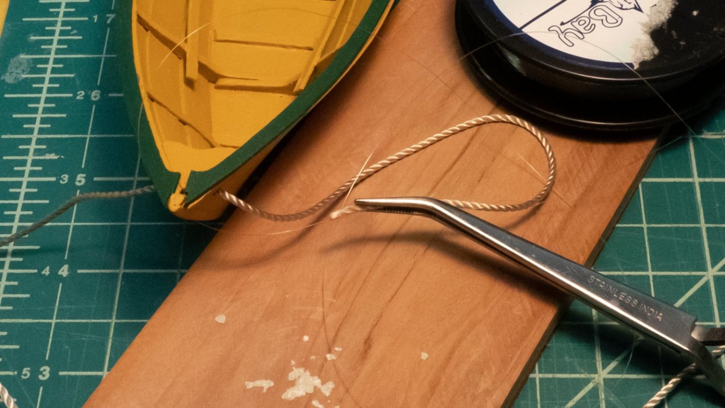
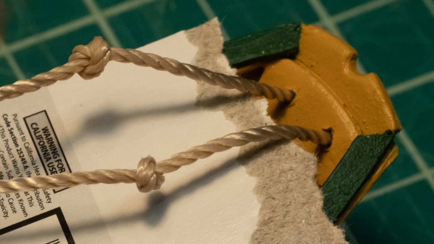
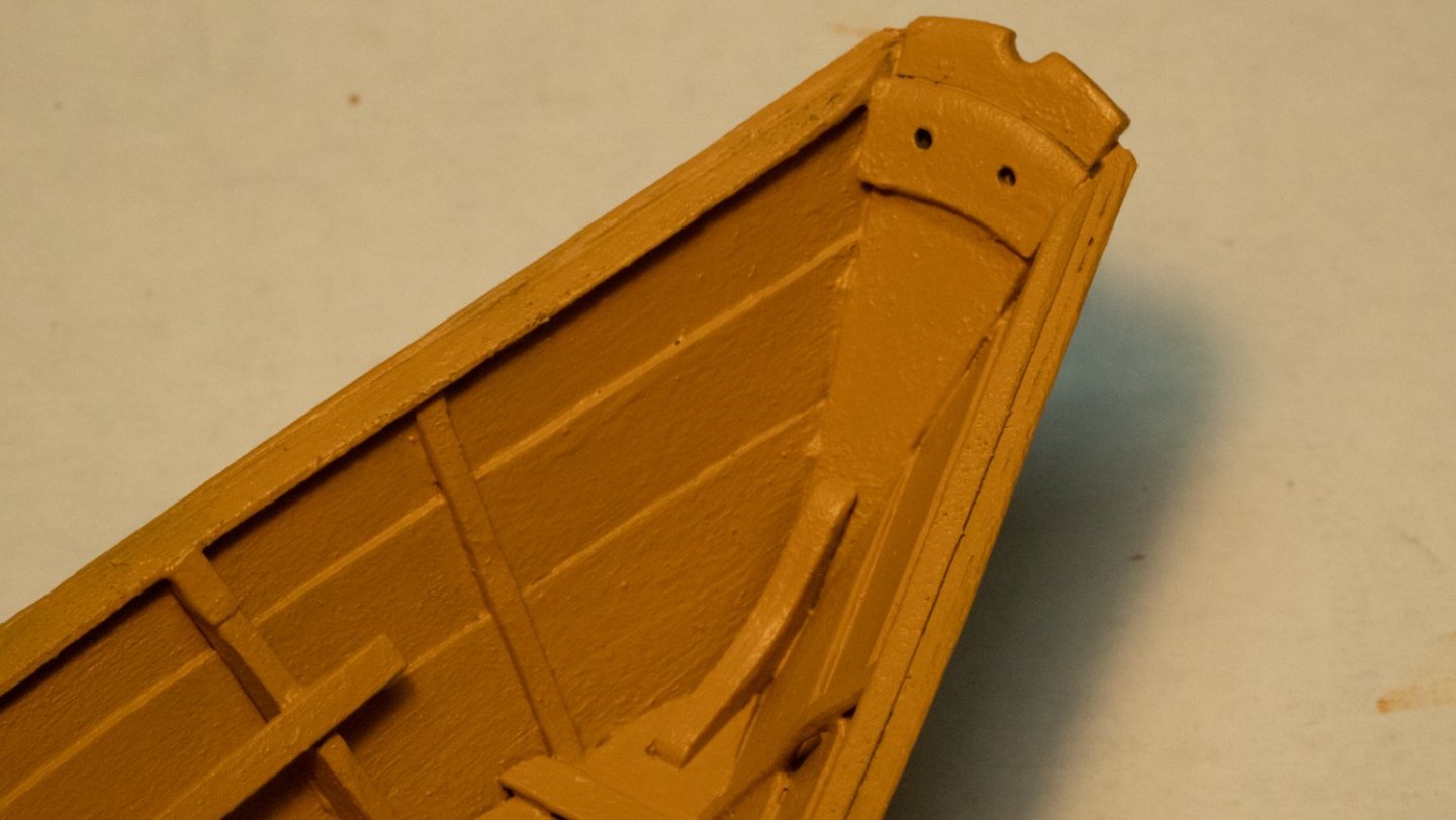
I received the 1.5mm line from Model Expo, and set to the final task of adding the beckets. I practiced threading this through a scrap piece of wood, using the method described in the instructions (use some white glue on your fingertips to glue the strands together and make a "point"). Twist the line as you're inserting it into the hole to keep the strands tight together. Once I had done this through four holes in the scrap, I started on the transom. I drilled out the transom holes and inserted the line. Then, to the bow. I drilled out the holes, then inserted the glued end of the line in. It went in great - one to go! Then I ran into a problem - I could barely see the becket hole from the inside. I tried to use some cross-lock tweezers to insert the line into the hole, but it was too clumsy, and I wasn't able to twist the line as I had done before to work it through the hole. Some options: expand the hole a little, or reverse the becket and have it hanging outside the bow, which no one would really care was "wrong". I though of electrician's fish tape, and wished I had something like that to pull the line through. How about fishing line? That might work. I threaded fishing line through the hole, tied it to the becket a few inches back, and then wrapped it around several times. I used the tweezers to position the line right at the hole and pulled the fishing line. To my surprise, it came through on the first try. The picture below shows how the tweezers were used, but obviously after the line had already gone through. I knotted both beckets and put some dilute glue on them per the instructions, and clipped the ends off when it was dry. I put dilute glue on the transom becket and hung the tweezers on it to pull it down, as shown in the instructions. During this process, I popped off two of the thole pins, which were glued back on. If I did this model again, I would put the beckets in when they are called for in the instructions, but I didn't have the line at the time.
- 40 replies
-
- 3
-
-
- Lowell Grand Banks Dory
- Model Shipways
- (and 1 more)
-
That's a very nice model, and a wonderful build log! Every step in the build and the log was well done.
-
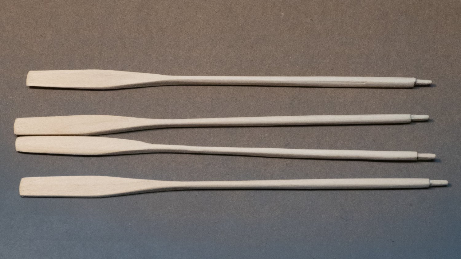
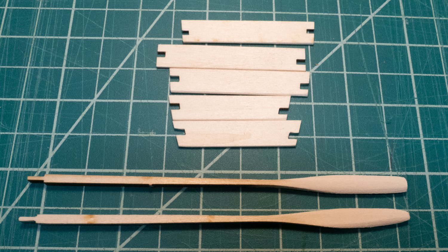
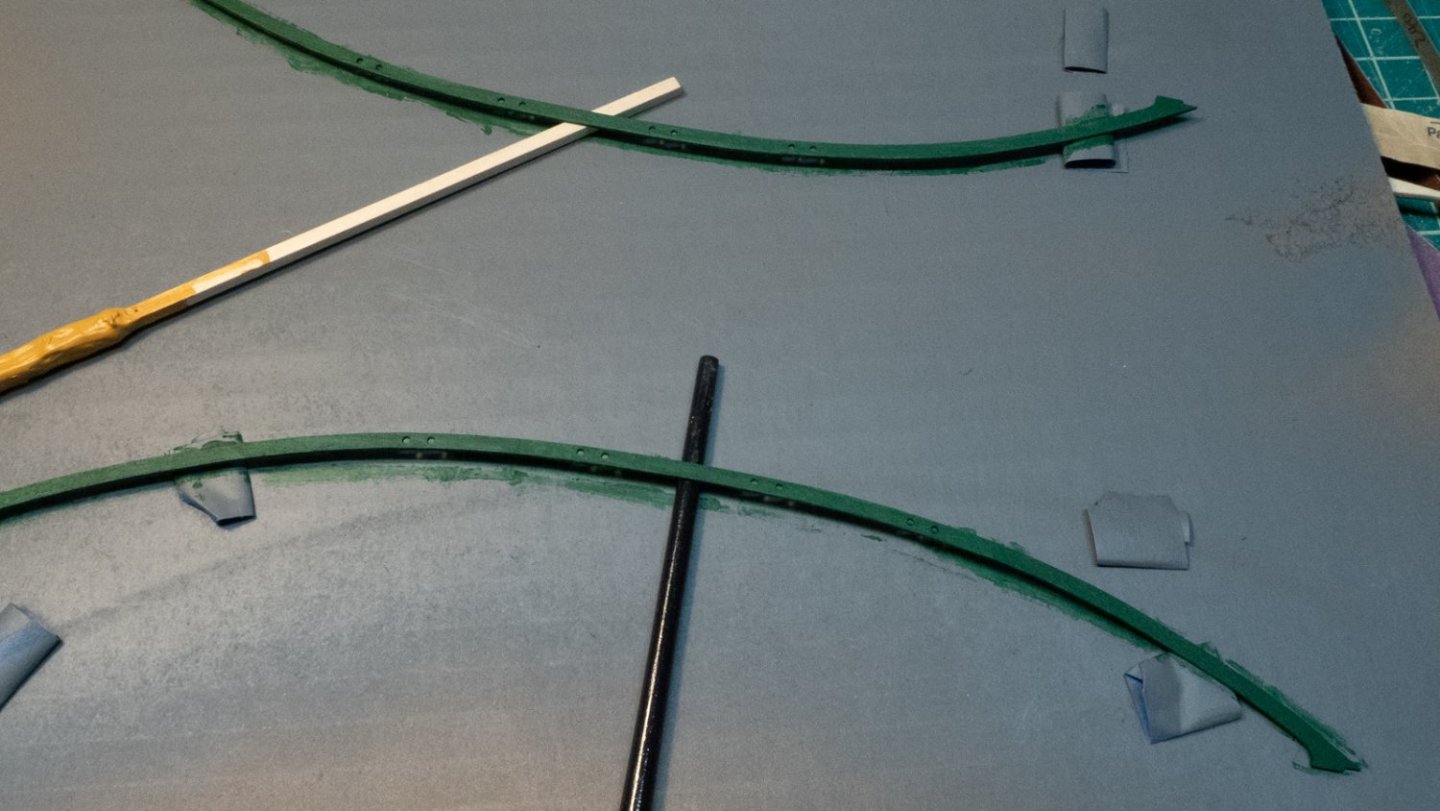
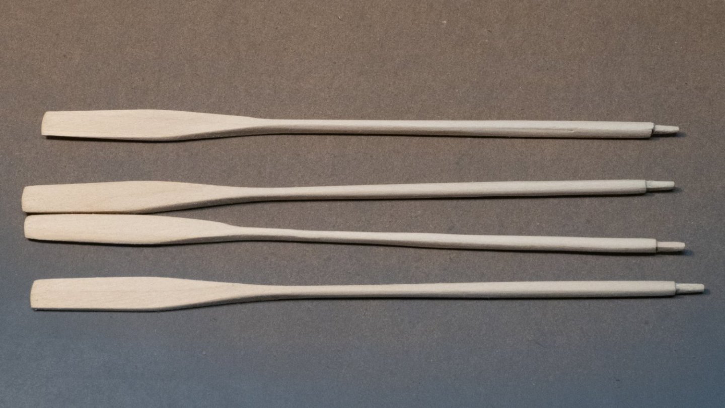
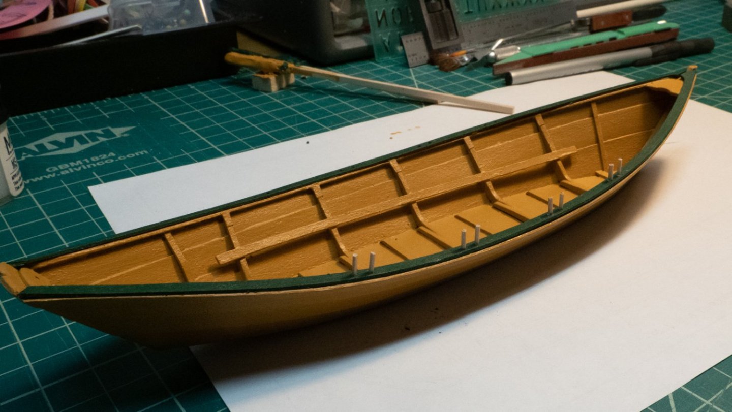
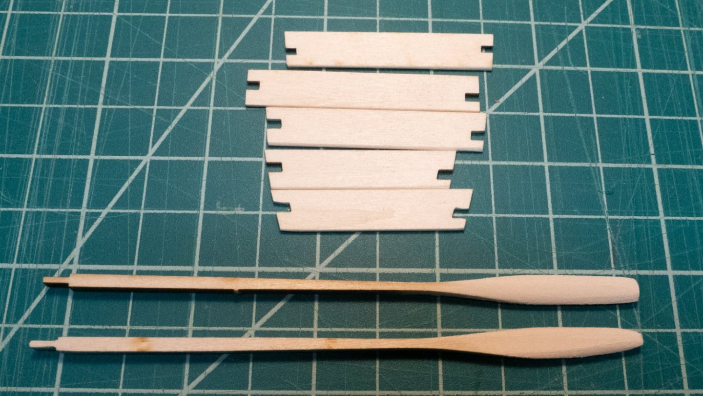
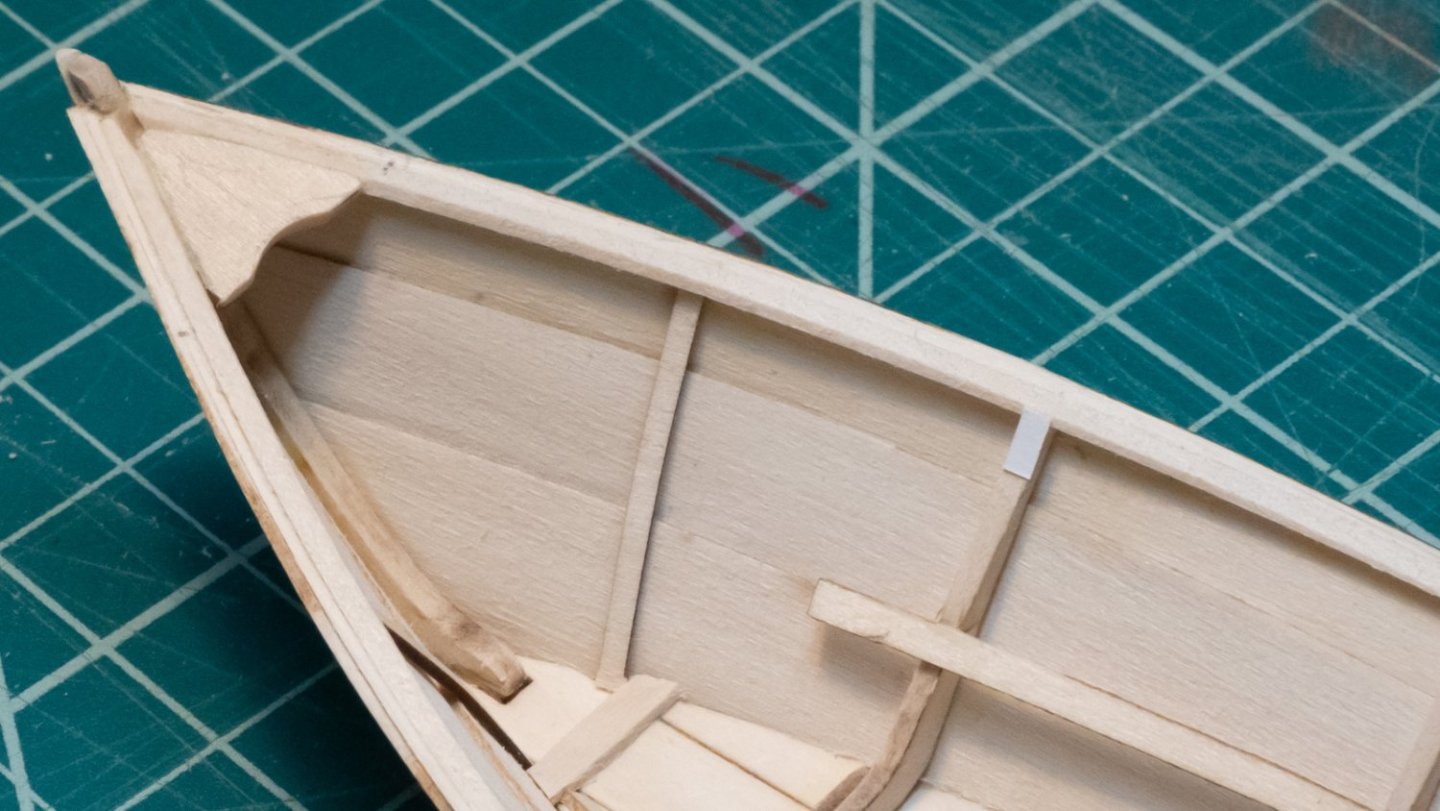
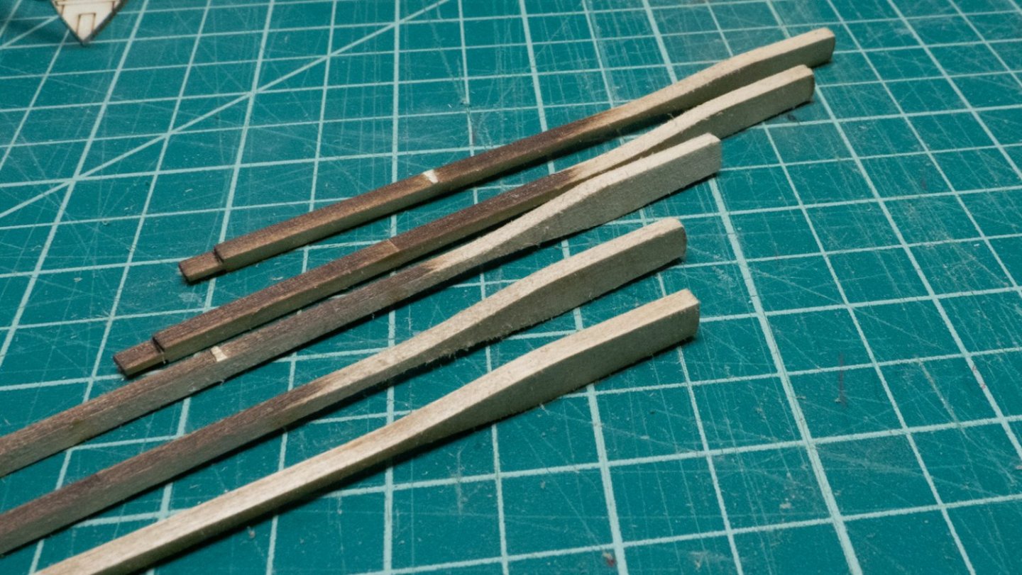
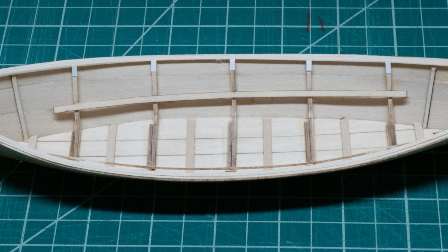
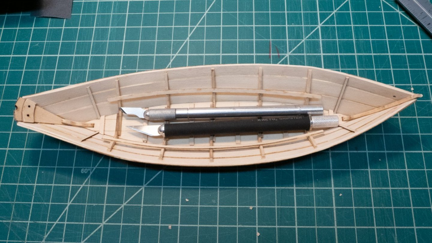
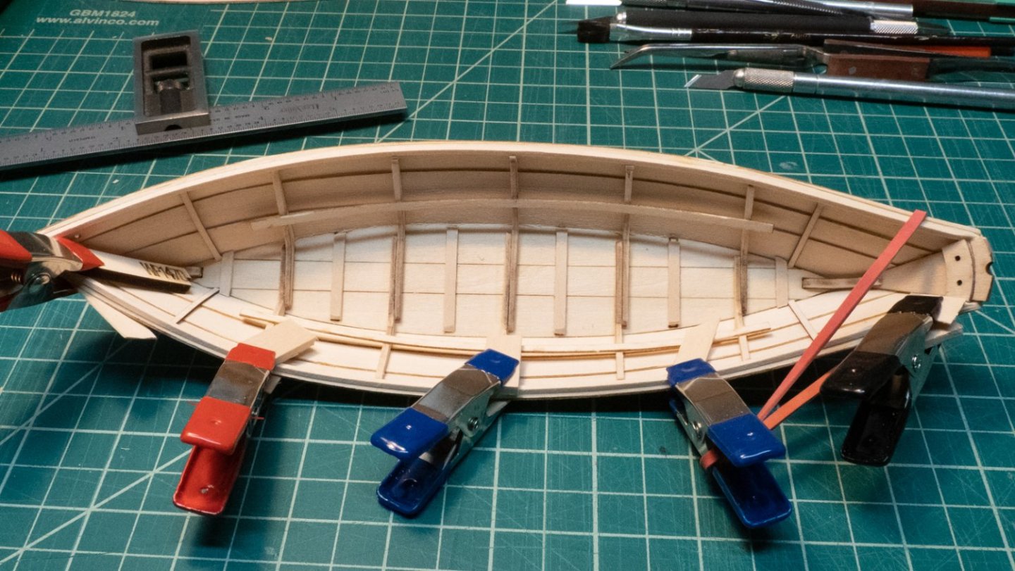
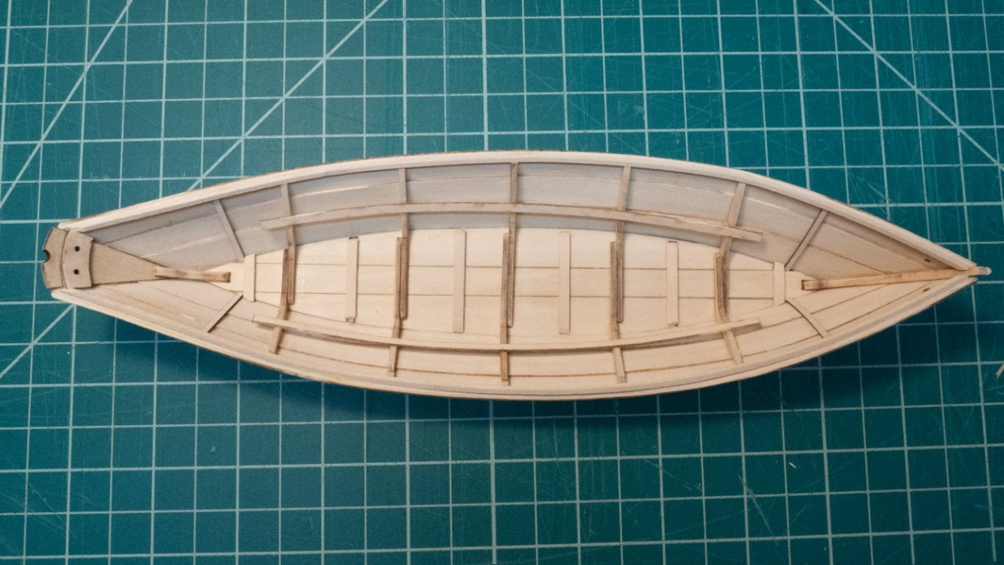
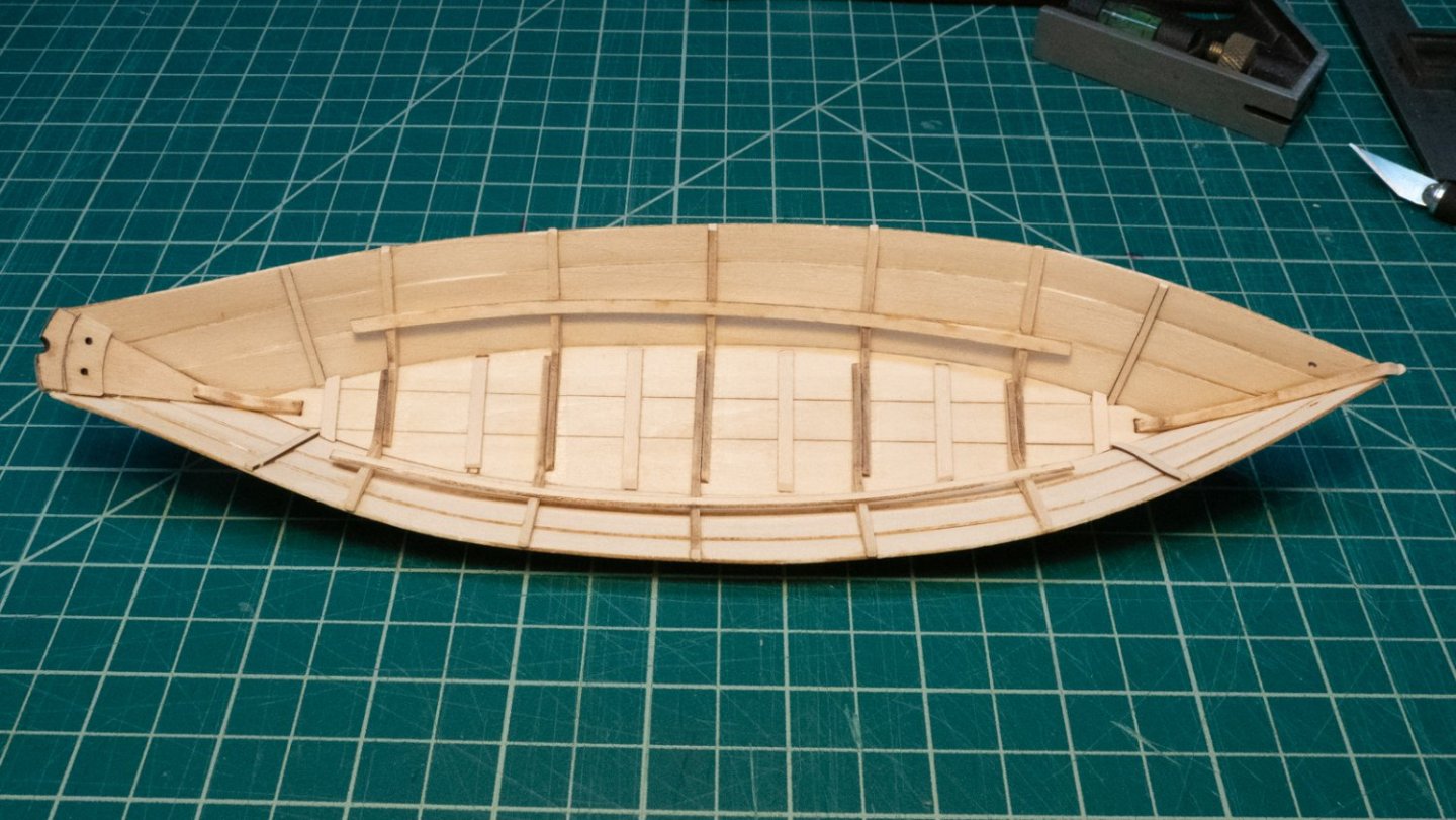
Cap Rails, steps 19 and 19a: I added the cap rail after priming and painting with two coats of bulwark green. I scraped off some paint from the gunwale for the wood glue to have something to grab onto. I started by gluing about 2 inches of the cap rail at the bow. I held it for a while, then moved on to put more glue farther down. I was patient and gave it time, but the glue was not working. I used liquid CA glue instead, and it worked great. Usually I end up gluing my fingers to whatever I'm working on, but spreading on a little with the point of a pin was sufficient. I worked it down to the transom, then clipped the end off with two scissor cuts to get it to the right length. The scissors sort of shredded the end, and I used a sanding stick to smooth it off. Cutting with scissors exposes an unpainted end to the cap rail - I went back with some green paint to touch up the transom ends. Naturally, this got some green paint onto the transom, which subsequently got an ochre touch-up. I need some better paint brushes for these small areas. Most people fill in the gap between the bow ends of the cap rail, but I like the gap, so it's staying. Step 22, the thwarts: It took me a few minutes to realize that they only go in one way. Put them in the wrong way and you'll see what I mean. Some were too long to sit onto the risers; I sanded down the ends to help them fit onto the risers, and filed out the notches with a small square file where needed. Step 23, the oars: I got better as I went. I basically sacrificed the first one trying to figure out what to do. The first two after that don't look as good as the last two, but they're pretty good and have only a tiny variation between them. I had trouble with the very narrow ends being consistent, though; I sanded them all to be a little shorter than provided, hoping that would reduce the appearance of the obvious differences. I sanded down most of the wide ends with 150-grit to flatten them out, holding it flat to the workbench and sanding horizontally across. When they were mostly the right shape, I shifted to 220-grit to smooth them out and round out the edges. To round the handles, you don't have to do much after shaving off the corners - you're almost at a round shape then. I didn't use the vise instructions in the booklet, just held the oar in my hand while sanding it. This picture is of the oars before I sanded down the narrow ends a bit more to hide the inconsistencies. The rest are pretty uniform, although there are differences if you look closely enough. The thole pins (Step 24) were next. I made my thole pins in pairs instead of making them all at once. The dowel was slightly larger than the holes (probably due to paint), so I rubbed the end of the dowel on 320-grit sandpaper while spinning it to make a slightly tapered end. When that fit into the hole, I cut it off at 1/4" using the "rolling blade" technique described in the instructions. I then cut the second of the pair the same way, and put them both into their respective holes to ensure they were the same height. Even if there are variations between the different pairs of thole pins, I wanted each pair to be the same because it would be noticeable if they weren't. I dabbed a tiny bit of wood glue onto the tapered ends of the pins and set them into the holes with tweezers. I inspected the pair and nudged them around with tweezers until they were parallel and looked right. I worked my way down each side, checking the lengths against any previous thole pins and making sure they were uniform and parallel as possible. Here's the starboard side. Next steps: I ordered the 1.5mm line for beckets from Model Expo last week, and when it arrives, I'll add the beckets. Then I'll post some final pictures here.
- 40 replies
-
- 3
-
-
- Lowell Grand Banks Dory
- Model Shipways
- (and 1 more)
-
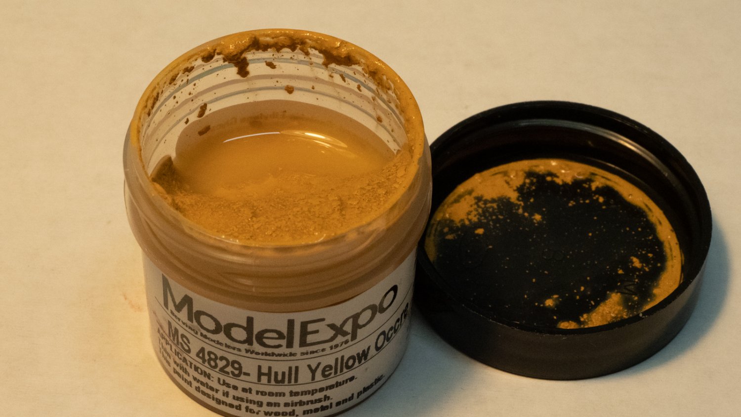
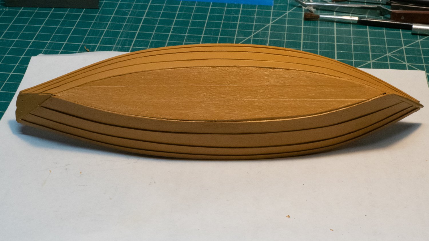
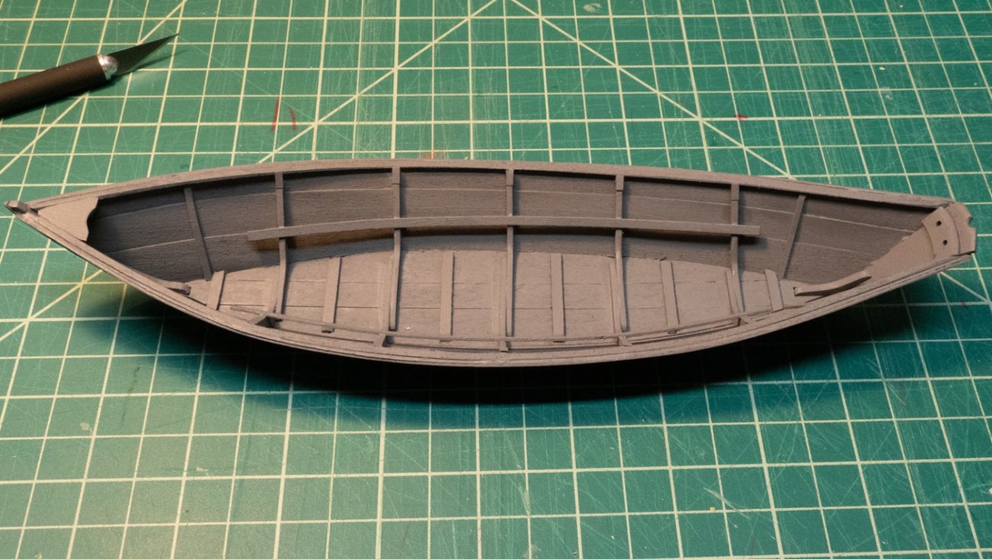
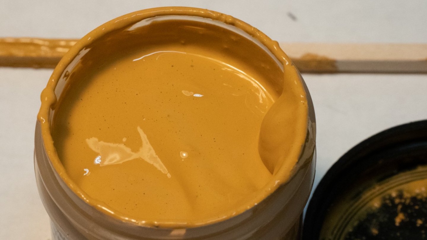
In several build logs, people mentioned that the provided becket rope is too large (2mm) for the becket holes in the kit pieces (about 1mm). I noticed the same - either the rope needs to be a different size, or the holes need to be significantly expanded. I sent a message to Model Expo to ask them about it. The 2mm line is what was supposed to be in the kit. They offered to send me 1.5mm line as a replacement at no charge, which looks more "scale" to the model, and which would still require a little expansion of the existing holes. I have ordered this line with some other items and expect the shipment in a few days. I appreciate Model Expo's offer to send this for free. I completed the stern (step 19), by sanding lightly with a sanding stick, and then beveling the inside of the steering oar recess with a round file. Next, painting. I sprayed inside and out with grey primer from a rattle can. One coat on the outside and one coat on the inside were sufficient. I opened the ochre paint jar, and the paint components were separated. I mixed it with a small stick for a long time, and it was still paste-y. I put a few drops of water in to thin it and mixed it well until it was a better consistency. There's not much to show as far as painting, so even though I took pictures after each coat on the inside, I'm not showing them here. It took three coats on the inside and three on the outside to cover the primer and have a consistent color. I used a 1/4" wide flat brush that came with the kit. The inside was a bit of work - there are a lot of corners and hidden spots. It helps to look at what you've painted from both fore and aft as you go. The outside was much easier. I painted the length of each plank, then moved to the next, then the next, smoothing it out as I went. I did the bottom last. The becket holes are now painted over, and I will drill them out when I get the new rope from Model Expo so I have the right size. As paint was drying, I continued to work on the oars. I took too much off one of them and rounded it off too much - I used that mistake to learn from as I started on the others. You can see in the picture below the bottom oar was sanded too much, and the top one is better. I just held them in one hand and sanded gently with a sanding stick. I also sanded the thwart edges with a sanding stick, so they're ready to go. Next up is the second step labeled as Step 19, the cap rail... P.S. The secret weapon on my workbench is a spray bottle with water in it. I don't have a water source in my basement where I work. If I need a little water, I can spray. If I need more than that, I can open the top and pour. I use it, along with several plastic bowls, to clean paint brushes and a lot of other things.


- 40 replies
-
- 5
-
-
- Lowell Grand Banks Dory
- Model Shipways
- (and 1 more)
-
Thanks for sharing this. What a cool build!
- 17 replies
-
- 4
-
-
- Edmund Fitzgerald
- Lake Freighter Minis
- (and 2 more)
-
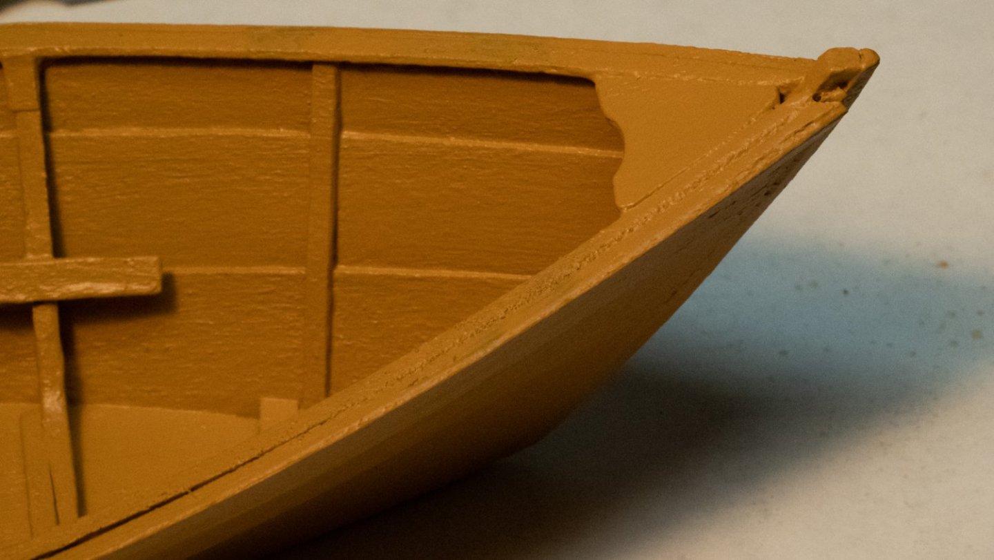
After taking a few days off to think about it, and read responses, I did remove the old piece and make a new one that I'm happy with. 🙂
-
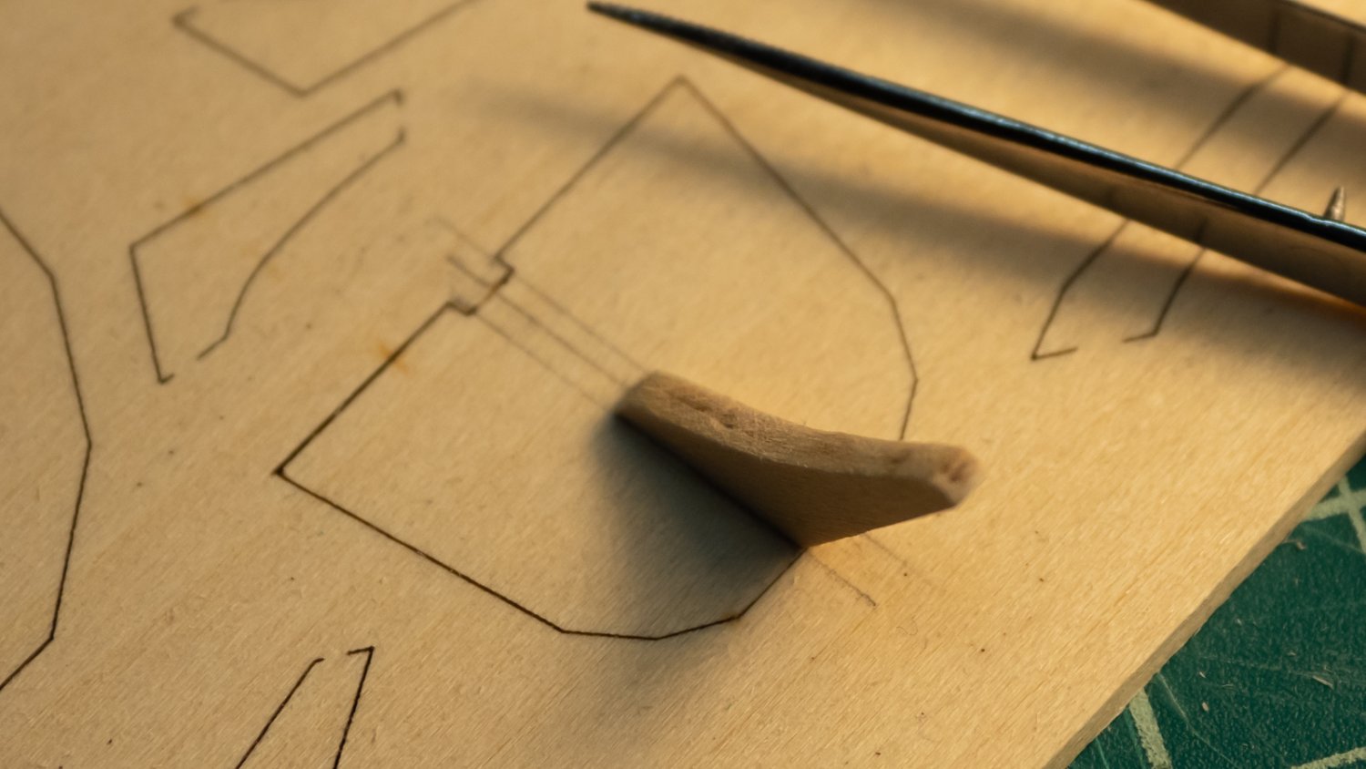
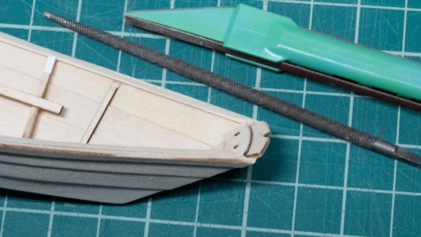
I went on a mini quest for filler advice - I had bought some bondo filler at a nearby store, and the smell was too much for me. This thread was lively and helpful. After all that, though, I made a new breast hook. I was able to get the old one off by softening the glue with water. I first used some card stock to create the basic shape using scissors, then I cut out a piece of the wood from the original breast hook parts sheet, and fit it by sanding and dry fitting. 220 grit sandpaper wrapped around a ball point pen handle made the concave shape. This looks pretty good, better than in the photos below, and appears to be a tiny bit bigger than what's shown in the instructions. I'm glad I went back to replace it instead of using filler. While I was thinking this reconstruction over, I started sanding the oars with a small, loose piece of 150 grit while holding the oar in my other hand. I removed the char completely from one oar, and will wait until making the handles round to remove the char from the rest. Next, step 19 (Completing the stern) and painting.

- 40 replies
-
- 5
-
-
- Lowell Grand Banks Dory
- Model Shipways
- (and 1 more)
-
Not big gaps - just a little to fill in around the breast hook on this dory. Once the filling is done, it will be painted. The sawdust and PVA idea seems like a reasonable solution for this size gap. I can try it on some scrap wood and see how it goes. And thanks (so far!) for the other ideas and thoughts on materials and other things. I am intrigued by the suggestions and will give some of them a try. I appreciate that not all product warnings are dire predictions of physical doom, however, the two items I tried had a pretty strong smell that made me leave the room, which is enough for me to want to avoid them.

-
I'm working on my first wood model and have a need for a little wood filler. Someone suggested auto body filler or a good wood filler. Without looking at the packaging, I bought some bondo filler at a local hardware store, and when I got home and read the instructions, it warned that it could affect my eyes, damage my hearing (it said this twice!) and basically, try not to be anywhere near this stuff. I thought I'd try a tiny dab to see what it was like and how it worked, and I can still smell it in the house the next day. While I can see how smoothly it went on, and why people like it, I definitely can't use this. I had some hardware store wood putty I have only ever used outside, and while its warnings were less alarming, it still asks for a well-ventilated space, don't breathe this, etc. So - is there an option for wood filler that doesn't have these kinds of warnings? I work in my basement, and one of the reasons I like modeling and hand-tool woodworking is the quiet, plus the lowered risk of damaging my hands or eyes or lungs. 🙂
-
I finished sanding across the gunwales and checked progress from side to side using a straight edge. I skipped step 17a (frame head irons) in favor of doing the breast hook (step 18). The provided piece was not the same size or profile as the one shown in the instructions. I shaped it, and glued it in. It was hard to hold, given its very small size - clamping tweezers helped. I thought I had it in properly, but it was not flush after drying. I popped it out and tried again. There are a few very tiny gaps, and I will leave it as is rather than risk damage to nearby parts if I try to remove it again. If I built this model again, I would consider constructing a larger breast hook with the same beginning design and angles as what the kit provides. Something even 30% larger would have been easier to hold with clamping tweezers or even fingers. Back to step 17a: The instructions indicate that the frame head irons are to be scale 3" x 4", and the pictures in the instructions did not appear to have that size ratio. After trying a few things, I settled on scale dimensions 1.5" x 4.5", which looks more like the pictures, and because those values, scaled, at 1:24, are easy to find on a ruler. I will consider filling in the gaps at the breast hook, and preliminary trials show that there might be a gap between the cap rails. Recommendations are welcome - the instructions mention auto body filler. Next up is (maybe) filling and primer.
- 40 replies
-
- 2
-
-
- Lowell Grand Banks Dory
- Model Shipways
- (and 1 more)
-
Moving to the second part of step 16, sanding the tops of the bands/sheer plank: my sanding stick was 320 grit because I wanted to be gentle with it, and it took a long time, but eventually holding a straight-edge across showed that things were ready for the next step. Step 17: Cutting the frames and installing the gunwales. The instructions say to take about 1/8" off the top of the frames, and I must have measured from the wrong starting point, because I took way too much off the first two I did. I cut off a 3/4" piece of the 1/16" square stock and used it as a guide for where to cut off the tops of the remaining frames and fore and aft cleats. I didn't have a #17 chisel blade, but I do have a #16 blade and a #1 handle, which add to 17. Ha ha. I cut down across the top of each frame carefully, and when I got to the plank, I chipped away the waste with a #11 blade. I put water on what remained of the glue and frame, and that softened it enough to scrape it away. When I was done cutting everything, I went back to the original frames and added some 1/32" pieces to build them back up to where they should have been. They shouldn't be noticeable. To put the gunwale on, I cut a slightly long piece from the provided stock. I wet it with a brush so it would conform to the sides while I measured it out. I started at the bow, where I had cut a 45-degree piece out of the bottom to fit the stem, then worked my way aft. I made some marks with a pencil and then cut the aft end. I brushed glue along the top of the inside of the sheer plank, on top of the frames, and at the bow and transom. Starting with the bow, I worked the gunwale along the inside, pressing down into the frames, then added some clips (making sure they did not cause the gunwale to shift). In the process of gluing and fitting things, I separated the starboard sheer plank from the transom, so I glued that back on as well (that's the reason for the rubber band in the picture below.) Next: sanding again, and considering the frame head irons (step 17a.)


- 40 replies
-
- 3
-
-
- Lowell Grand Banks Dory
- Model Shipways
- (and 1 more)
-
Good ideas. I used a q-tip to put the alcohol right where I wanted it, but it just soaked in and didn't seem to do much against the glue. The spring clips are the ones that came with the kit - they were just overkill on these steps.
- 40 replies
-
- 3
-
-
- Lowell Grand Banks Dory
- Model Shipways
- (and 1 more)
-
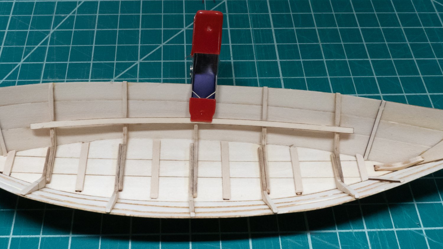
Step 15: For the seat risers, I made a small mark at the center of the riser, and lined that up with frame 3. I put a little glue on it, and clipped it to the frame, using a small piece of scrap wood on the outside planks to prevent damage. I rotated the riser slightly so the ends would more or less line up with the marks on frames 1 and 5. Was clipping this necessary? Probably not. When frame 3's glue was dry, I wet the riser a little on one side, put a little glue on where it meets the aft-er frames, and held it gently against frames 4 and 5. I discovered doing this on the first side that I had oversanded frame 4 when beveling it. If I were to do this again, I'd sand a little off frame 4 and 5, then test with a riser piece to ensure the curve matched that of the planks. It looks fine as is, but it could be better. I glued frames 1 and 2 the same way, then did the other side. Next was the band: I took the advice from the instructions to use the clips on this step, and I think I would have gotten better results had I not done so - the clips ended up squeezing the band enough to move it slightly down on the first side I glued, which I didn't notice until too late. I also think my technique with the clips was responsible for moving the bow end away from the false stem just a millimeter or two. If I were to do this again, I'd line up the first 3-4 inches at the bow, glue them, then hold them in place until they dried (2 minutes). Then I'd wet the remaining part of the band and brush some glue on it and move my way aft, holding it with my fingers. With just a little glue, it would only take a few minutes to glue the whole band in place. To add to the grief, a few of the clips squashed the shape of the band - I'll blame myself for not using the clips properly - lessons learned on this step for sure. I spent some time thinking about what I wanted to do with the misaligned band top. I wanted to remove it, then reglue it, so I drizzled 99% isopropyl on it, while holding the model upside down to prevent getting the alcohol in other joints. I put quite a bit on over the course of 10-15 minutes, and didn't see any signs of relief. I stopped, as I would rather have this be a little off than have an unforeseen side-effect in another joint coming apart. I'm currently gluing sandpaper to a piece of wood to use as a sanding stick in step 16, and pondering whether I want to take any other action on the band before continuing. I may do another round of alcohol, not sure...


- 40 replies
-
- 5
-
-
- Lowell Grand Banks Dory
- Model Shipways
- (and 1 more)
-
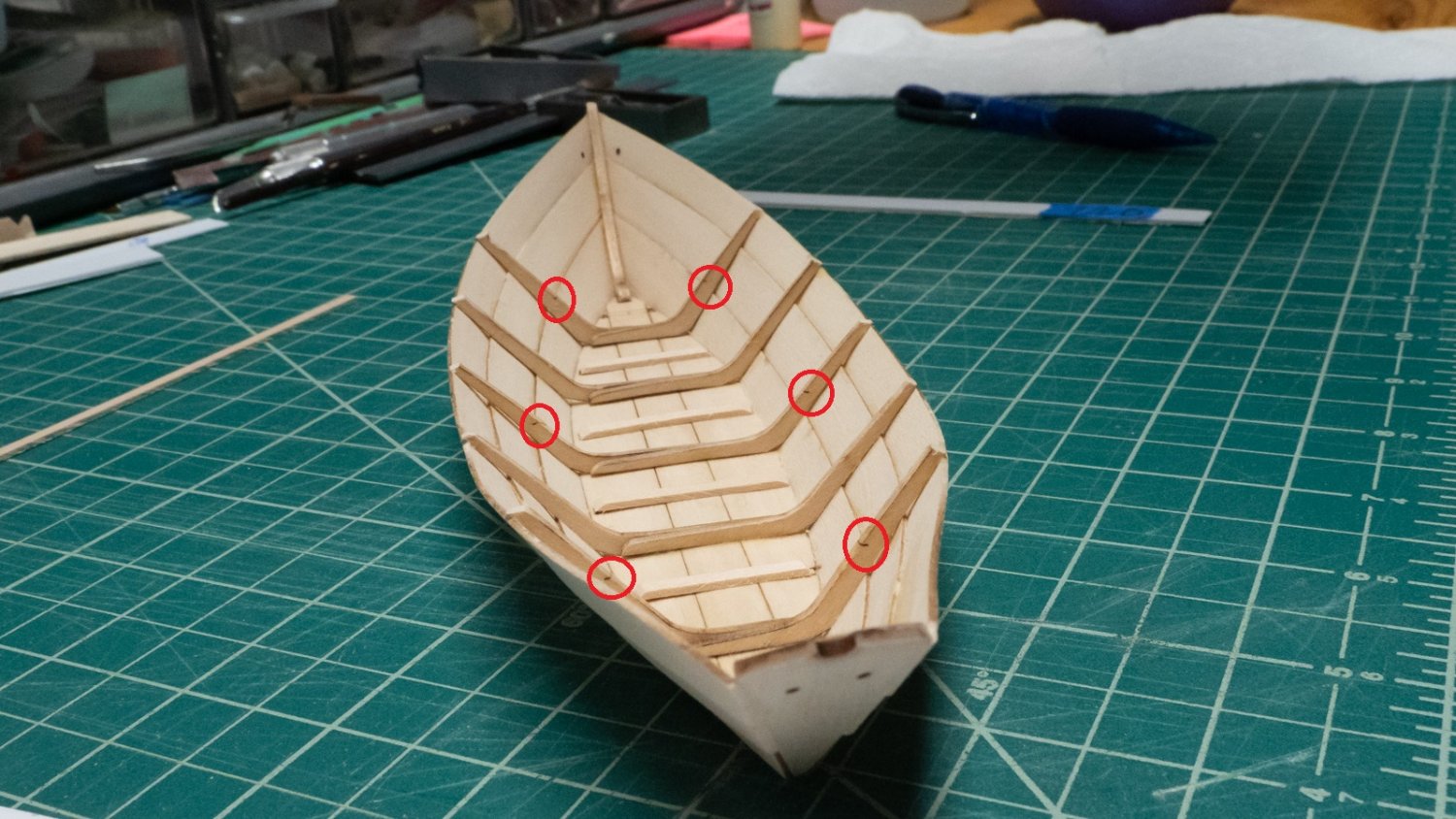
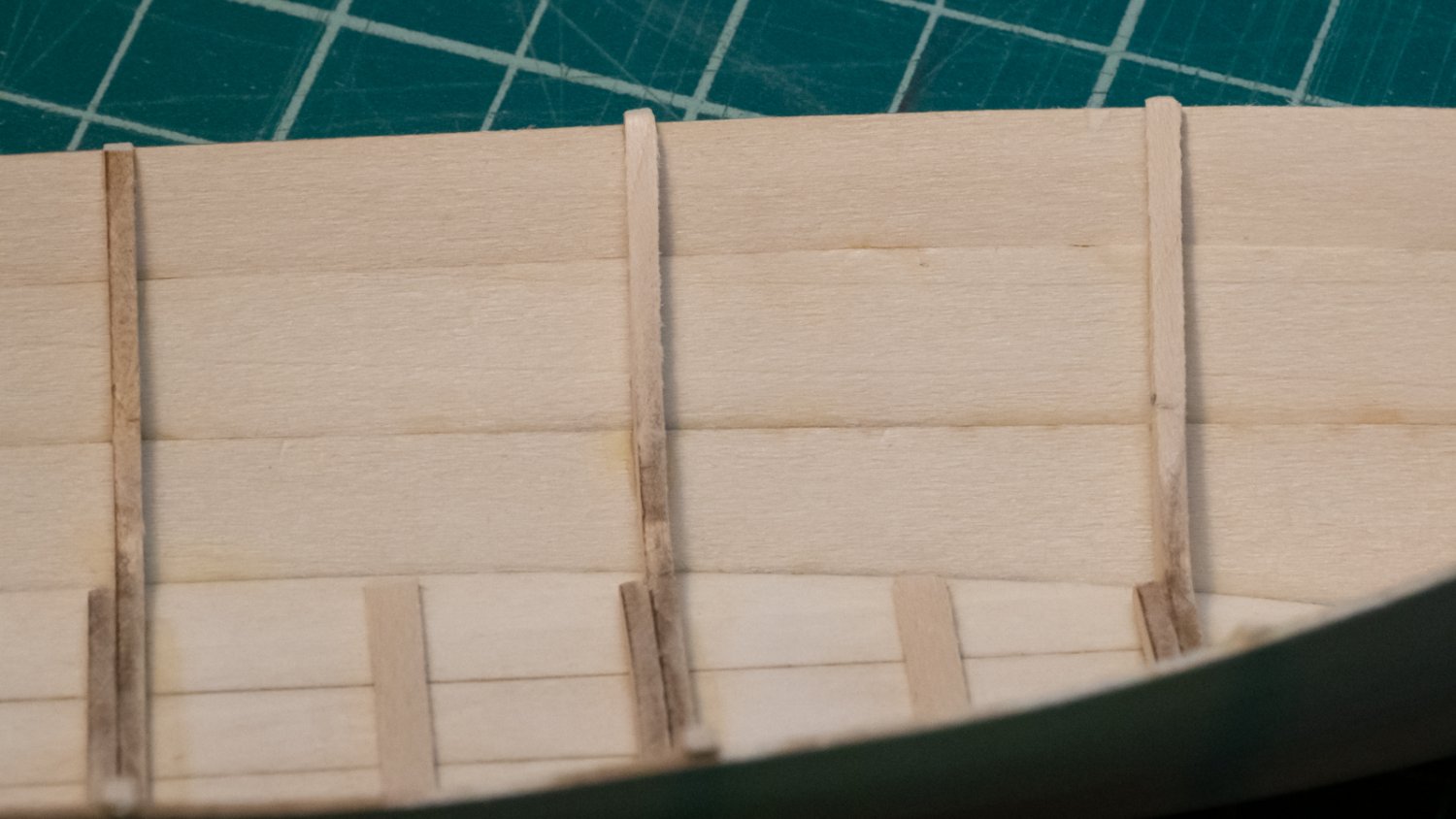
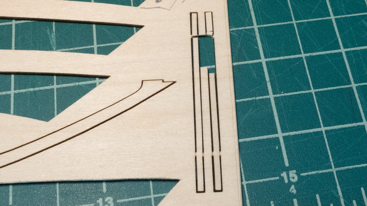
I noticed as I was looking at the next few steps that my cleats at positions 1 and 6 had disappeared at some point in the build. I replaced them. I was about to return to step 12a, but if you read ahead a few pages, you'll notice step 15 mentions the marks on the frames where the seat risers align, and some build logs have mentioned that they can't find the marks when they get to that step. That's probably because they sanded them in step 12a. The original frame marks are circled below, and you can see them before sanding. I took a pencil and extended them before sanding in 12a so I wouldn't remove them completely. Thank you to the people who mentioned this in their build logs - otherwise, I probably would have sanded them off too. As far as step 12a and what it means - I was confused at first. I was able to find the answer in another build log. It was what I had suspected: the "bevel" mentioned means to shape the frames inside to receive the riser, in a similar way to how the outsides of the frames were sanded to receive the planks. Here's a shot of a few frames that were sanded for step 12a. The leftmost one in the shot is frame 3, which wasn't sanded at all. 5 and 1 got the most treatment. I did step 13 (false stem) already, so on to step 14. I had a problem right off when cutting the side cleats out of the parts board: the grain is running across the width of the cleats, and that makes them very fragile. As I was cutting to free one side, I ended up "exploding" part of it, breaking off the end of one of the pieces in the process. I broke ANOTHER cleat on the other side of the parts board, even though I was being very careful. Fortunately, each side cleat had enough material left to glue it in one piece. I put a little glue on these side cleats and held them in position for a few minutes while the glue dried - I was afraid to use clamps for fear I would just break them in half. They are very pliable, there is no need to wet the inner part. Risers are next.


- 40 replies
-
- 6
-
-
- Lowell Grand Banks Dory
- Model Shipways
- (and 1 more)
-
I came out here with a question about step 12a (basically, that I didn't understand it), and found an answer in this previous build log. I have about 10 finished build logs bookmarked here and have been able to get lots of good information from them. In the meantime, I noticed that neither cleat 1 or 6 were still attached to the bottom. I must have popped them off at some point. Fortunately, those will be easy to fix. Onward and upward.
- 40 replies
-
- 1
-
-
- Lowell Grand Banks Dory
- Model Shipways
- (and 1 more)
-
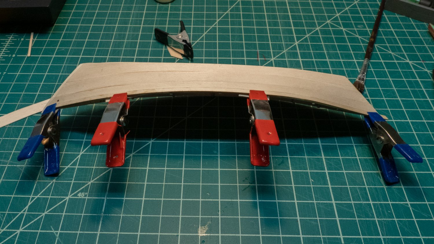
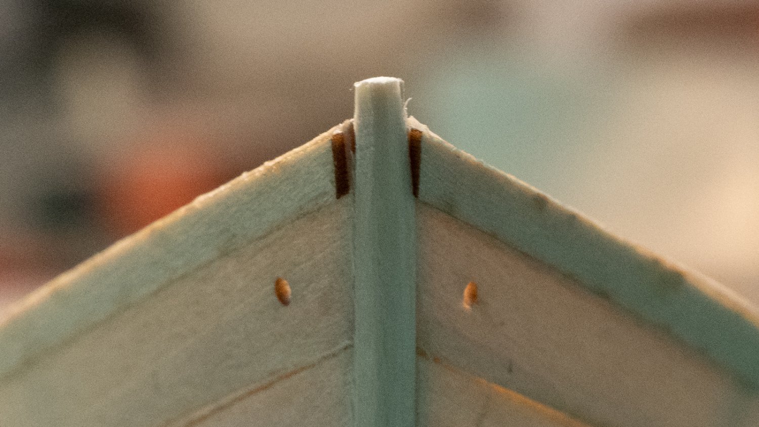
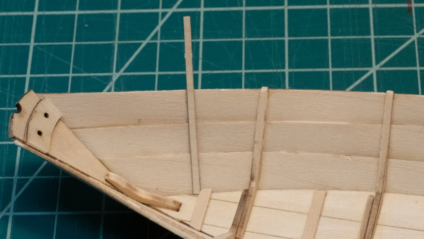
Looking ahead to the step with the false stem: This step generated a lot of comments in other build logs, and the instructions are vague - they imply there is a false stem piece included in the kit, and if there is, I couldn't find it. I looked at as many finished models as I could find that showed the bow in detail, and also checked for images of real dories online to see what the stem looks like. There are lots of different styles, some are completely smooth, some have a bulging false stem - most appear to have a "triangular" point. I noticed that the false stem step happens after removing the cross pieces and removing from the building board. I thought it would be easier to bend the false stem and glue it if it were still on the building board, so I skipped step 12 and went to step 13. I cut a 1/16" wide strip from a scrap piece of 1/8" basswood (use scrap from the kit that has a machined flat side), and sanded it down to about 1/16" square. I put a spacer under the first cross-piece to hold the bow off the board. Frame 3's cross piece came off when I lifted it out of the building board, but the rest stayed intact. I sanded the front of the stem where the planks meet to make sure there was a flat surface for the false stem to seat. I soaked the false stem piece in hot water and bent it with a flat side against the stem, then glued and used a few rubber bands to hold it in place. I sanded the false stem parallel to the planks with the goal of having a smooth, "triangular" look that blends the stem into the planks. I went back to step 12 and removed the building board and frame supports , and sanded the frames down. Some of the cross pieces just snapped off when I handled them. Next is step 12a to sand the inner sides of the frames, then step 14, side cleats.


- 40 replies
-
- 5
-
-
- Lowell Grand Banks Dory
- Model Shipways
- (and 1 more)
-
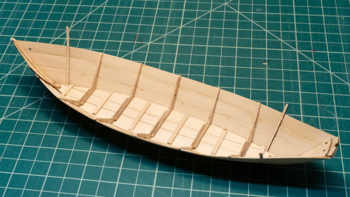
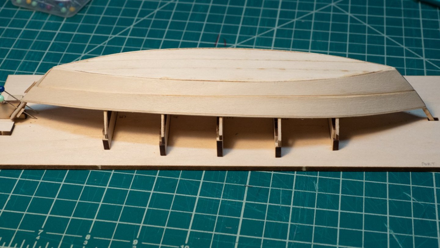
The last course of planks... I soaked the first and it was drying against the side of the dory while I worked on the other one. I was sanding the rolling bevel on the fore end a bit too hard and pushed some of the fibers off the edge of the bow end, taking off a "corner". It was enough material I had to decide what to do - go ahead with this piece or make another and use it instead? I made a duplicate piece from 1/32" basswood as a backup in case I needed it. I decided to glue the plank on the other side first, then dry fit both the damaged original and the copy, and see which one fit best. In the end, the original was good enough, so I used it. Shown after gluing, but before sanding it down to the stem. Before gluing, I put a 1/32" wood spacer under the second of the two planks to make sure the "top" of it would line up with the other. Because I had so much overhang at the transom, it occurred to me that the instructions to make the rolling bevel right at the end of each plank didn't make sense - the bevel really needs to be where the plank overlaps right at the transom. I made the 45-degree bevel longer so it would fit where it belonged, although it was just a guess, since it's hard to know precisely where the plank will end up at the transom before gluing. I never really got the hang of the method described in the instructions to use some dilute glue and hold in place with my fingers. Anything short of almost 100% glue didn't seem to stick well. I realized at one point that when I was using a brush with water to clean off the glue squeeze-out that I was probably accidentally introducing water into the joint as well, and washing the glue a little, so I was more careful in later steps when doing the same. I used pins and a rubber band to hold the transom end in place, although by the time I did all this, the glue was probably set. The heights of the two planks at the transom isn't identical, but it's really close, and I'm hoping a little sanding will even them out enough to the naked eye. I'm relieved to be at this stage. It was a bit of a struggle to get the combination of glue/clamps/rubber bands/blocks and positioning just right each time. The tip to use a little water to help the board be flexible is a good one - use it. Some pictures before sanding the transom and stem overhangs flush...


- 40 replies
-
- 5
-
-
- Lowell Grand Banks Dory
- Model Shipways
- (and 1 more)
-
Gorgeous, amazing details. Nice work!
-
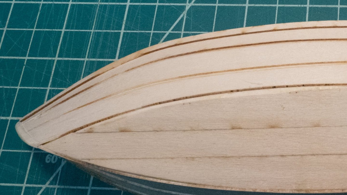
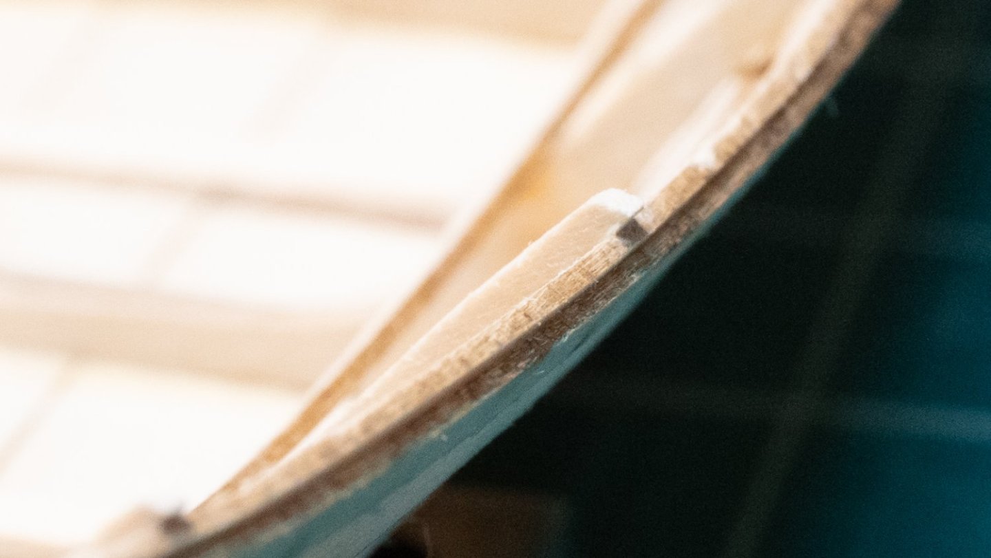
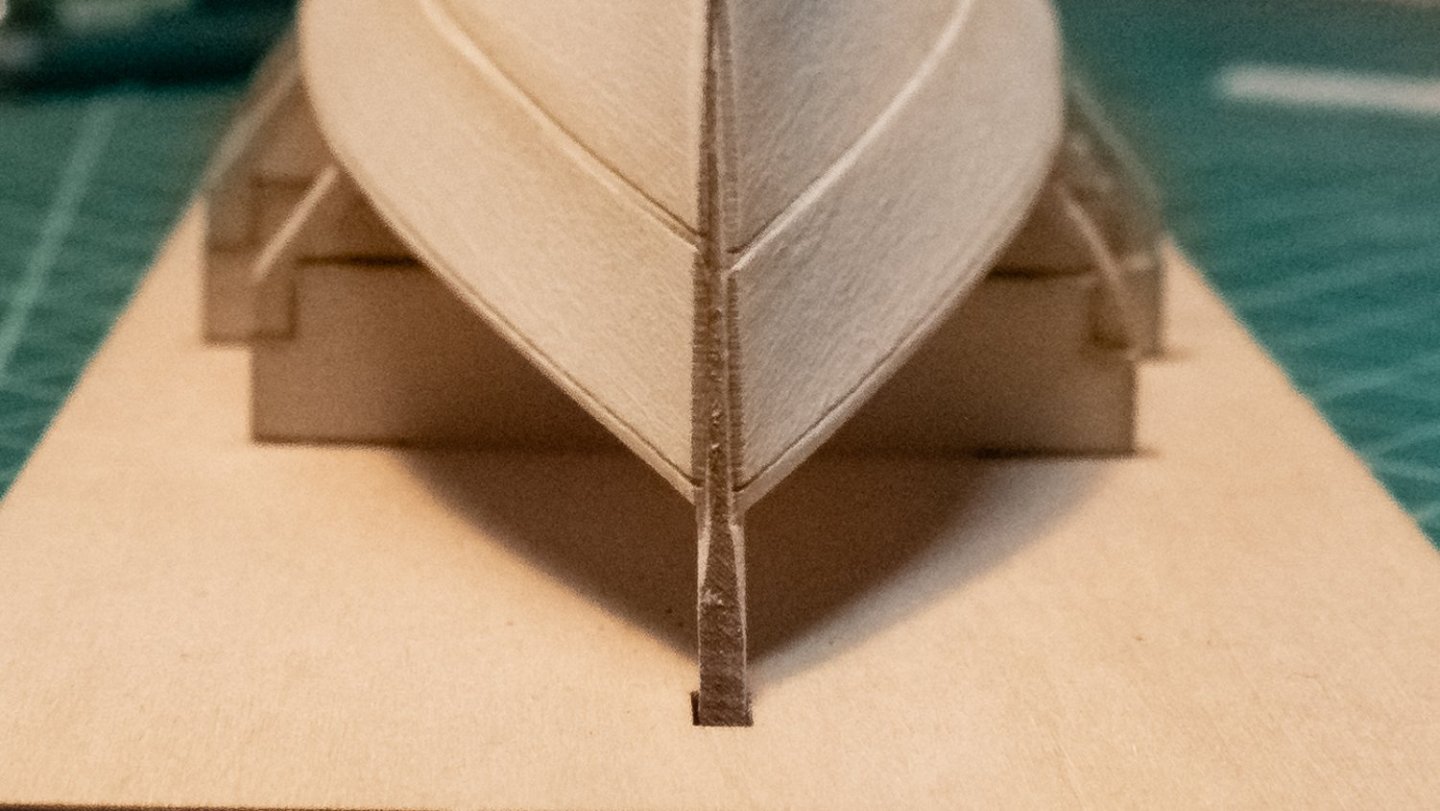
Today, I glued on both broad planks. My approach was to glue the stem end, and use a clip at the first frame to hold the orientation I wanted so I could work my way down the frames with minimal adjustments needed. My main goals were: glue the planks, avoid wetting the wood or making adjustments. This kind of worked, but I ended up wetting down parts of the planks on both sides around frames 4-5, and it was enough to give me that extra millimeter or so of bend I needed. The process from the instructions worked fine for the first plank: glue the stem and let it dry; apply diluted glue to the edges and frames; and work down to the transom. I put a few clips onto the frames/plank and the transom to make sure it stayed put after I took my hands off it. The other side didn't work well. I started the same as before, but when I started to apply glue to the first frame, the stem end came off. I tried it again, and this time I glued the stem AND the first frame, using clips at the frame and holding the stem with my fingers for a while. The process of moving from frame 1 down to the transom worked fine, and I left a few clips on a few frames to help it hold on for good. Here are a few close-up shots at the stem, showing the 45-degree tapers on the garboard and broad planks fitting together. In a previous post, I noted that the garboards were not at equal heights at the stem and transom; I made an effort to adjust the positions of the planks on the stem to try to get them as close to alignment as possible. The picture here shows that the two are a little closer now, and I'm hoping the next plank will give me the opportunity to line them up exactly at the top. I notice that the final plank will fit just barely above the building board. (Also, I need to do more sanding on the stem!)

- 40 replies
-
- 5
-
-
- Lowell Grand Banks Dory
- Model Shipways
- (and 1 more)