DonBMichigan
-
Posts
60 -
Joined
-
Last visited
Content Type
Profiles
Forums
Gallery
Events
Everything posted by DonBMichigan
-
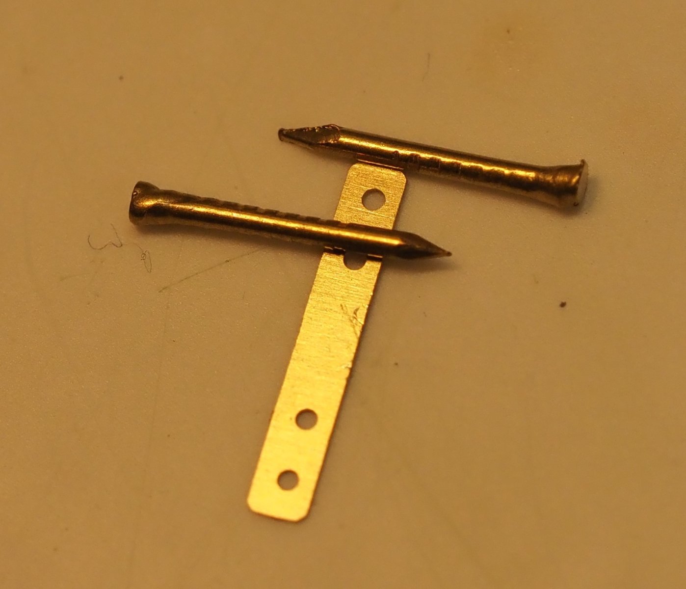
 I've been slowly returning to the pram after a long inactive period. I am in the brass fittings phase of the build, and I'm finding that the given nails are too big. They don't fit in any holes in the photoetched pieces. I have noticed this in some build logs - people cutting off the heads of the nails and gluing them, some people making their own "heads" out of wire, etc. and some models whose nail "heads" seem too big for the pieces they are securing. Some models appear fine, though, and I'm guessing that those models came with a size that works, or the modeler made something else to work there instead. Am I missing something basic, or are these nails just too big? I don't mind contacting Model Expo about some new ones. They only list 1/32" nails, which I presume the Pram kit nails are supposed to be, but the average width of the nails I have is over 1/32", more like 3/64". Thoughts?
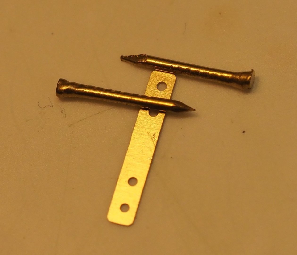
-
Focus Stacking
DonBMichigan replied to Dennis P Finegan's topic in Photographing your work. How to do this.
I have a few Olympus cameras, and have tried a number of different methods of focus bracketing: in-camera; using a tripod and rail; moving the focus ring manually and taking multiple shots; and using the Olympus Capture software to move the focus at each shot with the camera on a tripod. You can also just use the touch screen and tap along the image of the model from front to back and let the camera focus on each point. I have had difficultly getting in-camera focus stacking on my E-M1 mark II to work - with some effort, I've gotten OK results, but it's finicky IMO. I really enjoy doing macro photography and seeing how close up I can get, but I've not really tried hard to get amazing photos on the model pics I've posted here. I've used Zerene Stacker or Photoshop to stack. I've found the former to work very well, but if you already have Photoshop, it's usually good enough. -
I am still following this, you're doing a great job! I am really looking forward to getting back to the pram, then the smack (I'm moving to a new house, and selling my house, and I am surprised how time-consuming it all is). Your guides will be my guide for sure.
- 46 replies
-
- 2
-

-

-
- muscongus bay lobster smack
- Model Shipways
- (and 2 more)
-
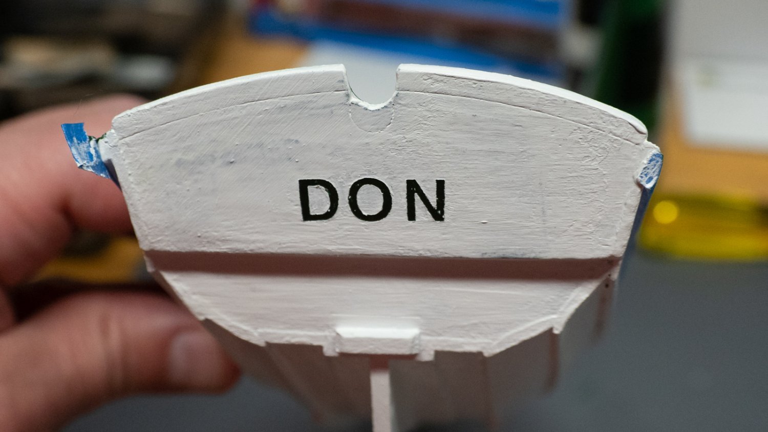
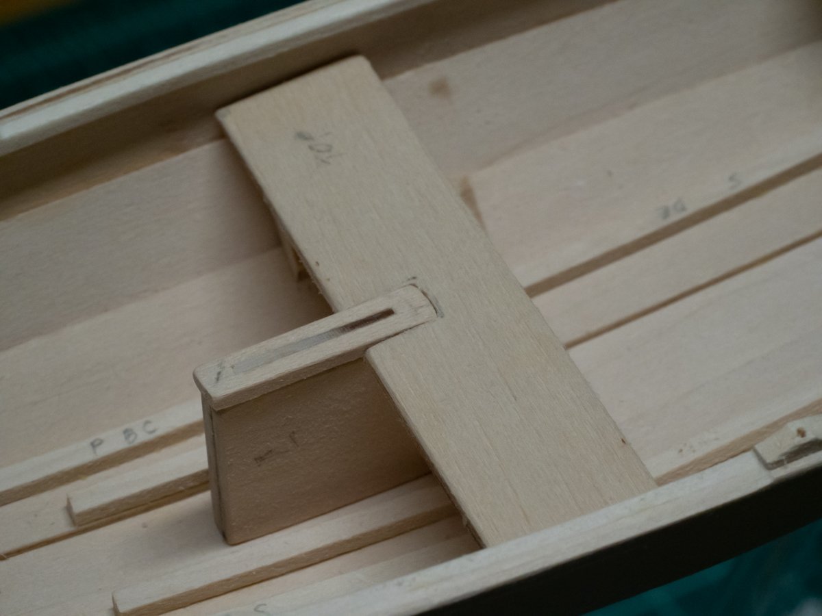
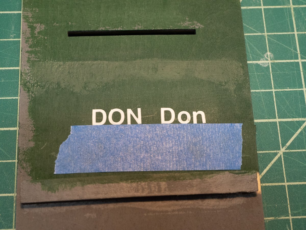
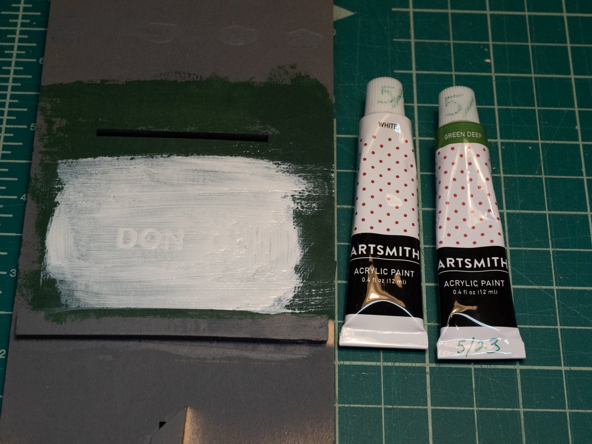
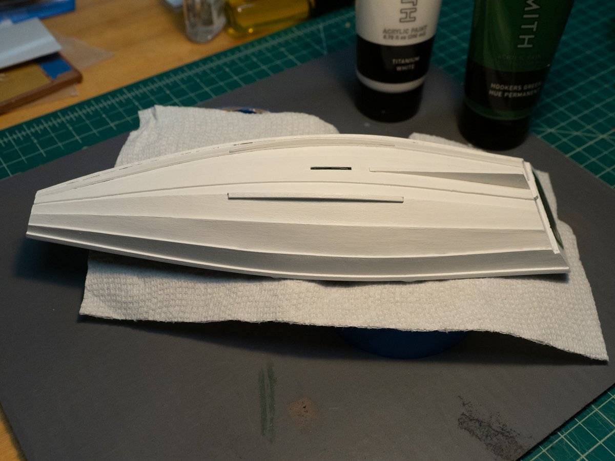
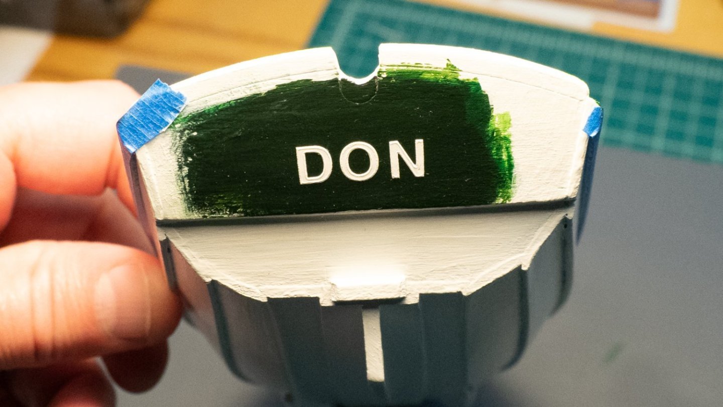
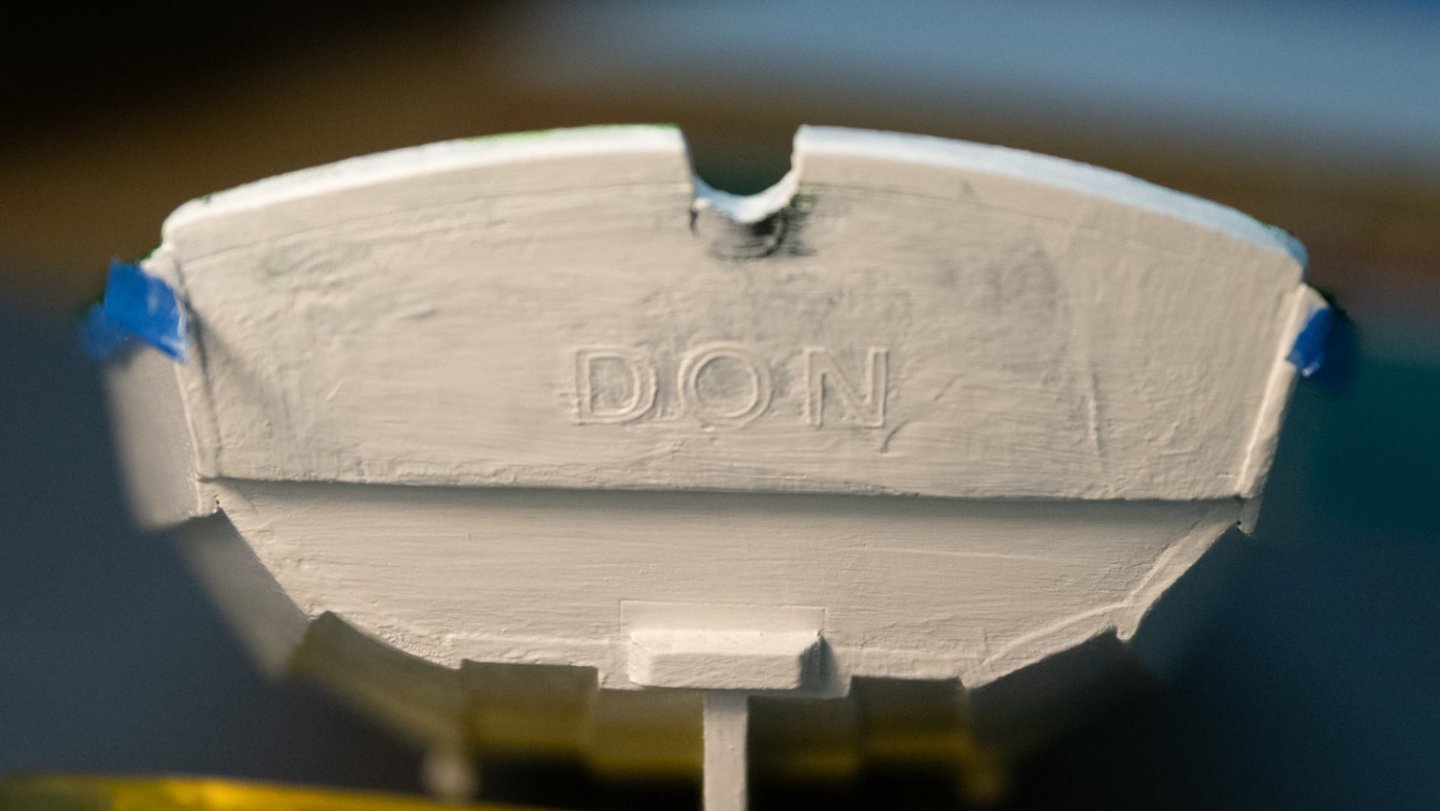
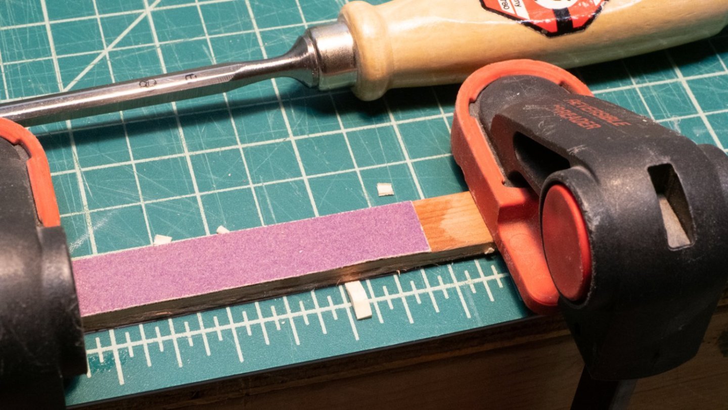
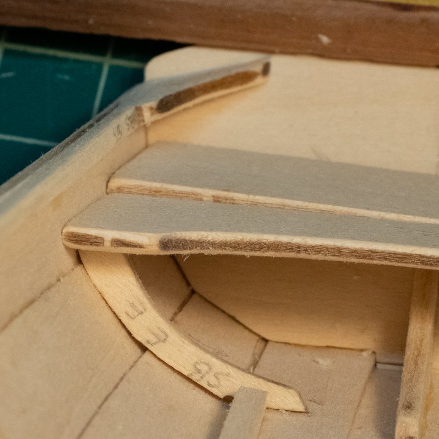
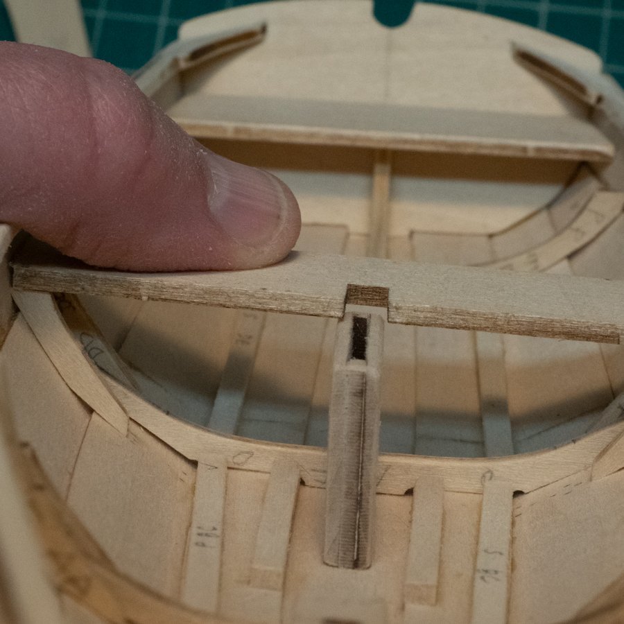
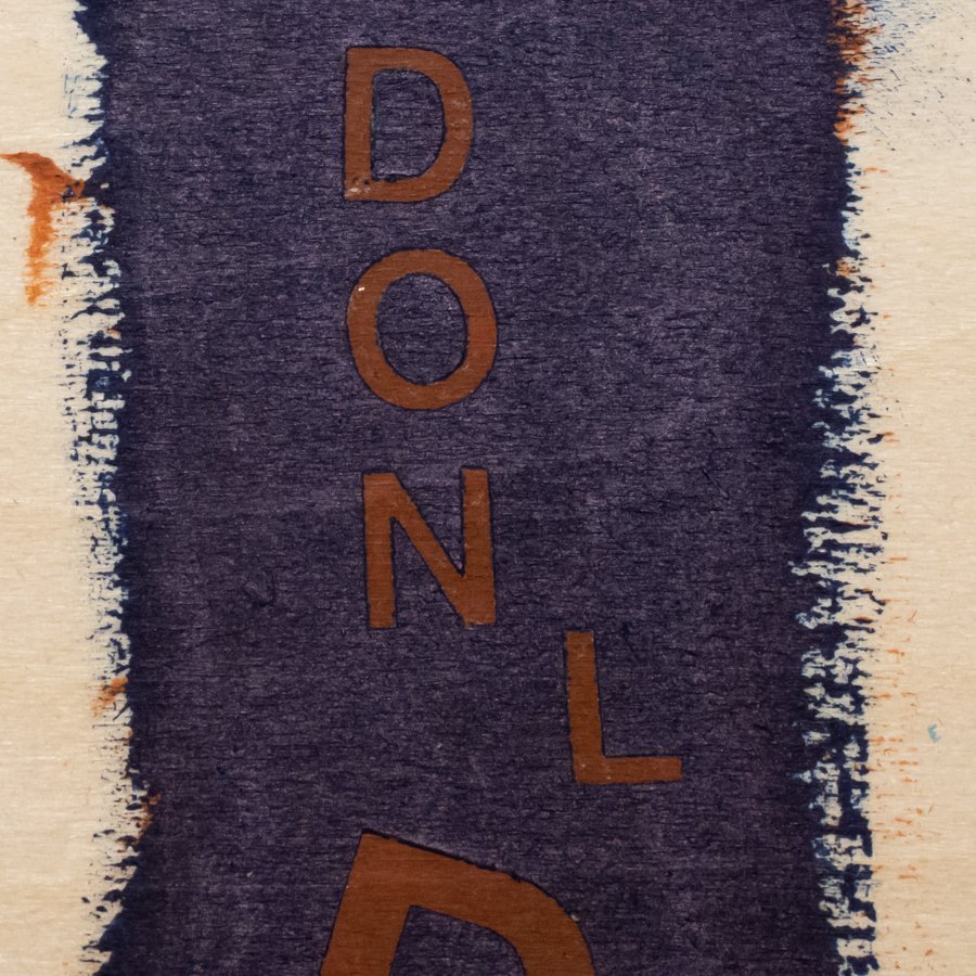
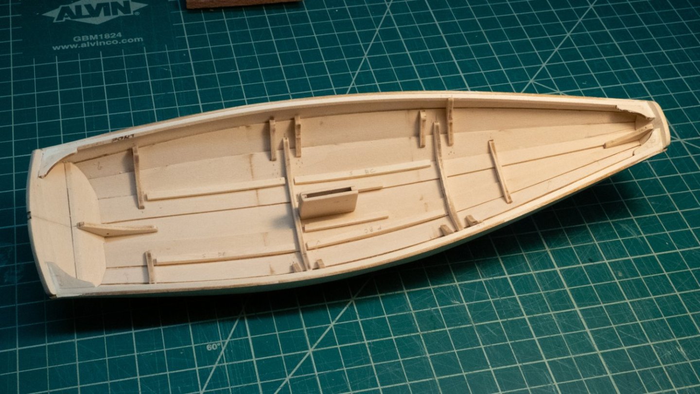
I've done a lot of small painting sessions with the pram over the last few weeks, and also continued to try the "lettering" method I read about somewhere else on this site (and I can't find it or I'd give the author credit). Before painting, I worked on the thwarts, leveling them off, and dealing with the height mismatch of the middle thwart and the dagger board case/dagger board. I am "owning" the mismatch, and carved out the right amount from the thwart to fit around the top of the dagger board, and it looks good enough. As for the painting, I'm using white and green paint I bought at JoAnn Fabric rather than what came with the kit. I used several coats of the white on the outside; something about the white paint makes it a little harder to spread than the green. The green seems to go on more smoothly. It's as if the white paint softens the previous coat when I apply it, because if I'm not really careful, the paint turns gooey and is harder to brush on. This might be my technique, the cheap paint, the brush I'm using, or my inexperience, or all of the above. 😀 As for the lettering, I wanted to try a technique where a base color was painted, some letter decals were placed on top of that, then another color was painted over the whole section of the pram. Once the top color is solid, the decals are removed with the sharp point of a hobby knife, and the base color is revealed. The following pictures show that: This is practice on a scrap piece of wood. I put on several coats of green, then put on the white letter stickers. Several layers of white paint went on after that. Once enough white paint was added, I removed the stickers. The paint stuck to the edges of the stickers, so the lift wasn't clean in a lot of spots. This looks pretty good, but not great, and since it's such an easy technique, I really wanted it to work, so I went ahead and did it on the pram, even though I didn't like the results of a few tests. I painted the outside white, and added some green on the stern. You can see I didn't really plan this out, for two reasons: I added way too much green, and I put the letters right in the middle, and they will be partially covered by the rudder. A way-too-large field of green as a base for the letters... Painting over the letters, and the rest of the stern, with white paint. After removing the stickers, still some of the rough edges are there. This technique might work better with an airbrush or different paints, I don't know. I'm going to leave this as is, and continue assembling the pram. I will probably wish I had moved the letters over to one side, and would do so if I tried this again. Life is going to interfere with much further progress in the near future - the summer has brought me a lot of new tasks, including moving to a new house next month. The tiller is next, and then some of the metal work.


-
Current steps: Priming and painting. I expect painting to take a while, as I'm planning to paint the outside white and the inside green. I have been trying some new paint, and I expect the white to take several coats at least based on my tests. I am also continuing trials with lettering, which are mostly promising but I'm still having some issues that I think I can fix in (what I hope will be) my final test round before applying the technique to the stern transom. The nice weather outside is going to cut into modeling time at this point - I am getting out of my basement and house and working on some yard projects, including replacing some rotting wood trim. So - all of these add up to some extended time on the model steps. Be back in a while!
-
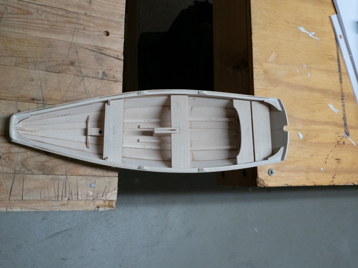
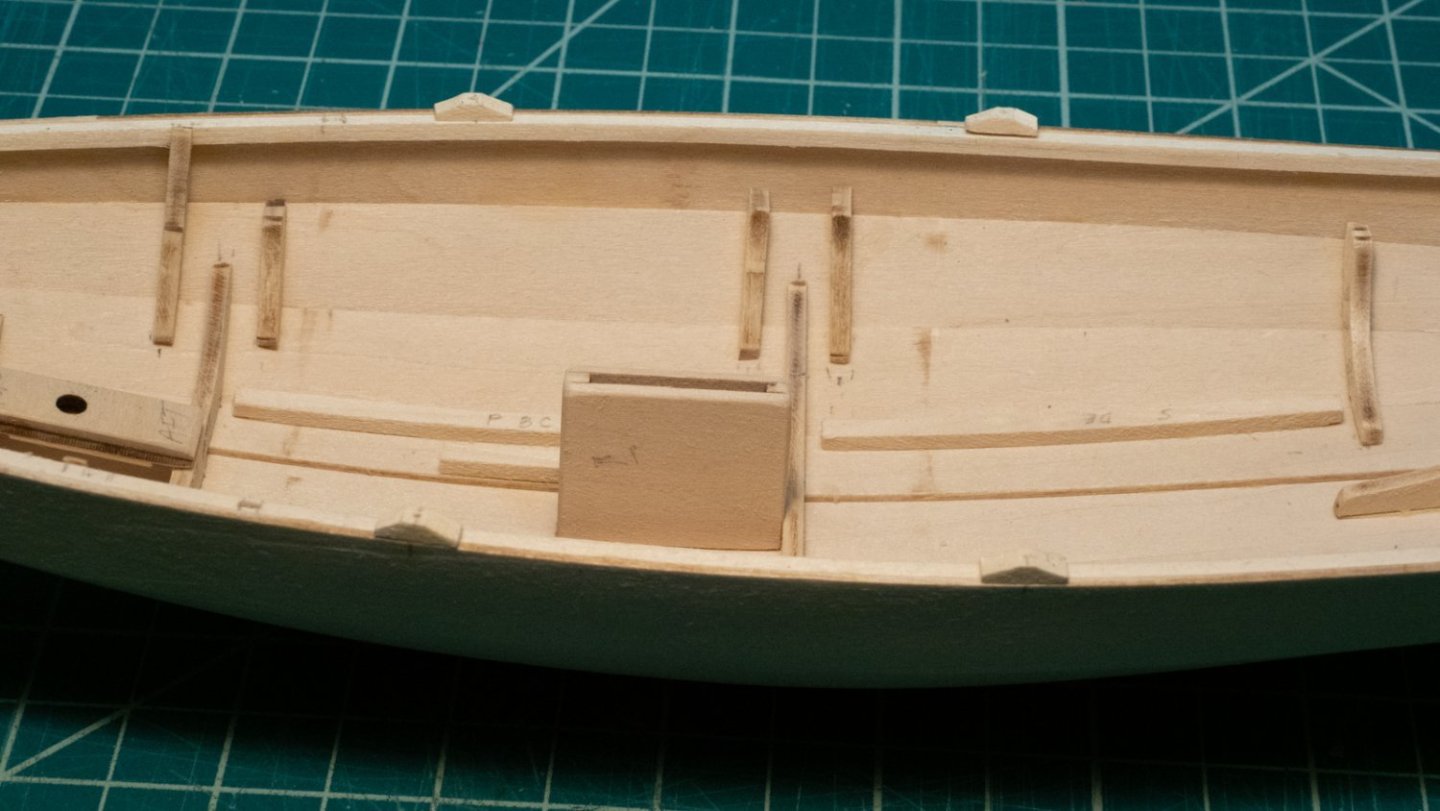
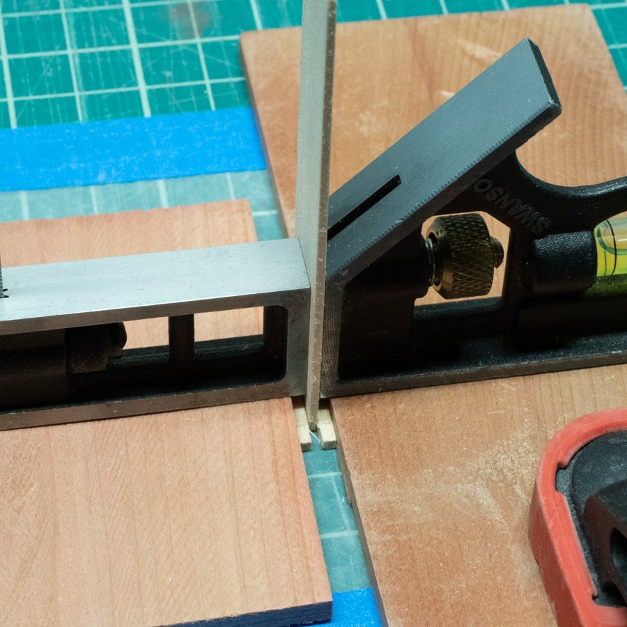
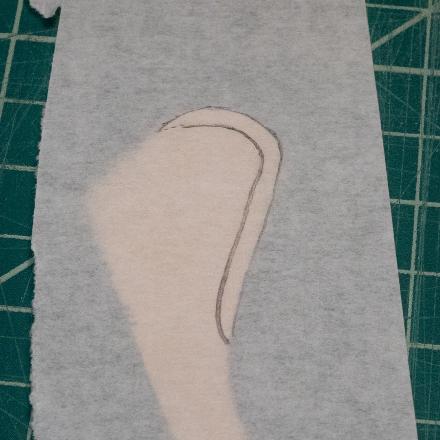
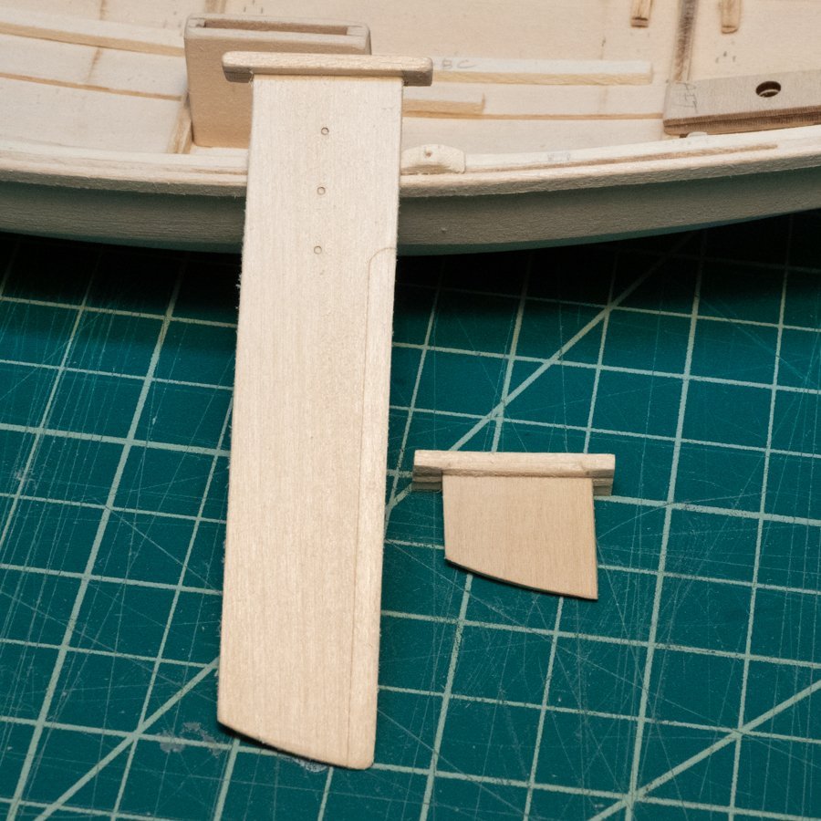
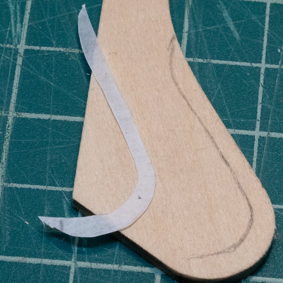
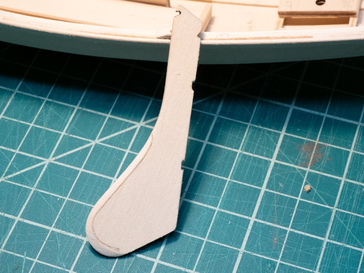
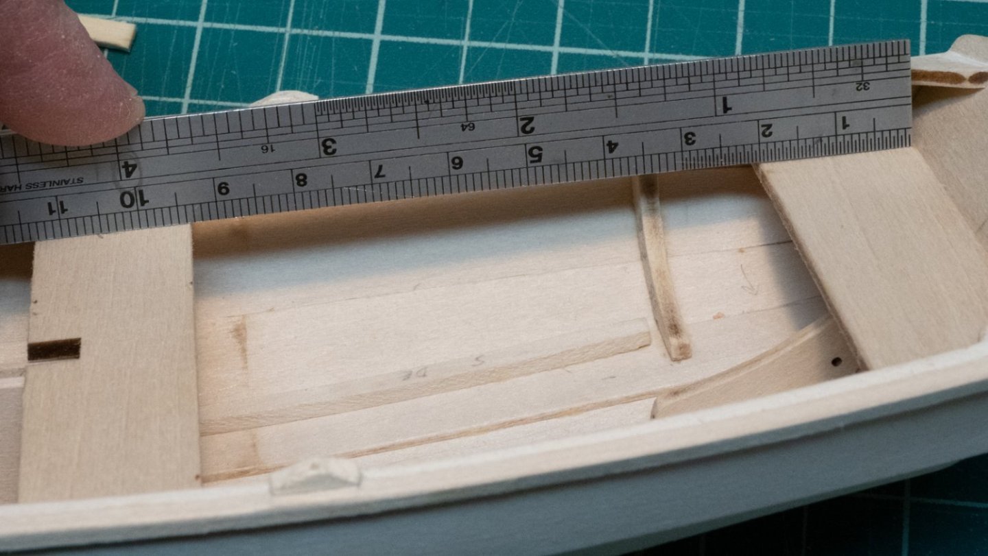
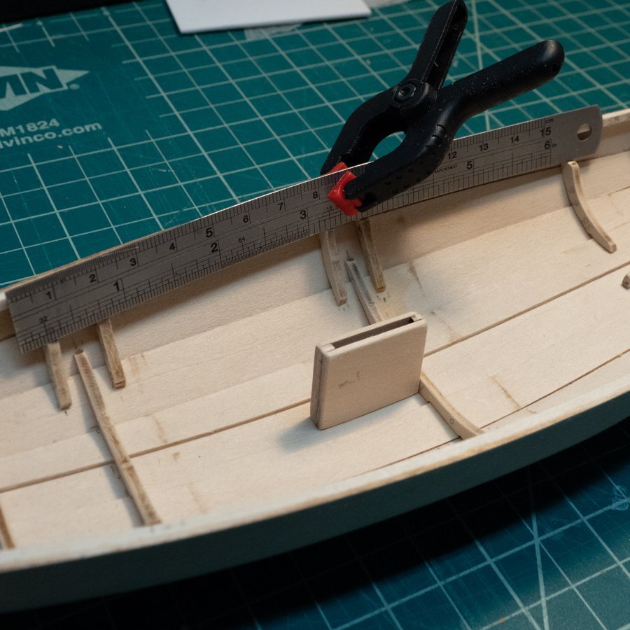
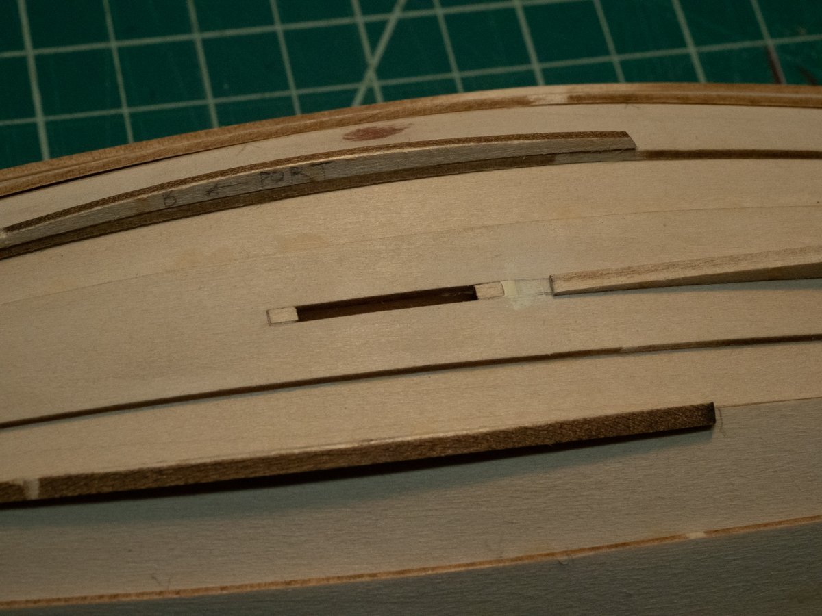
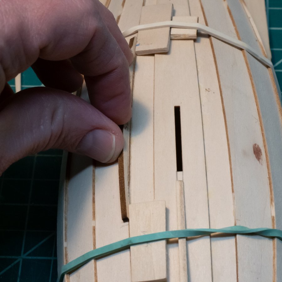
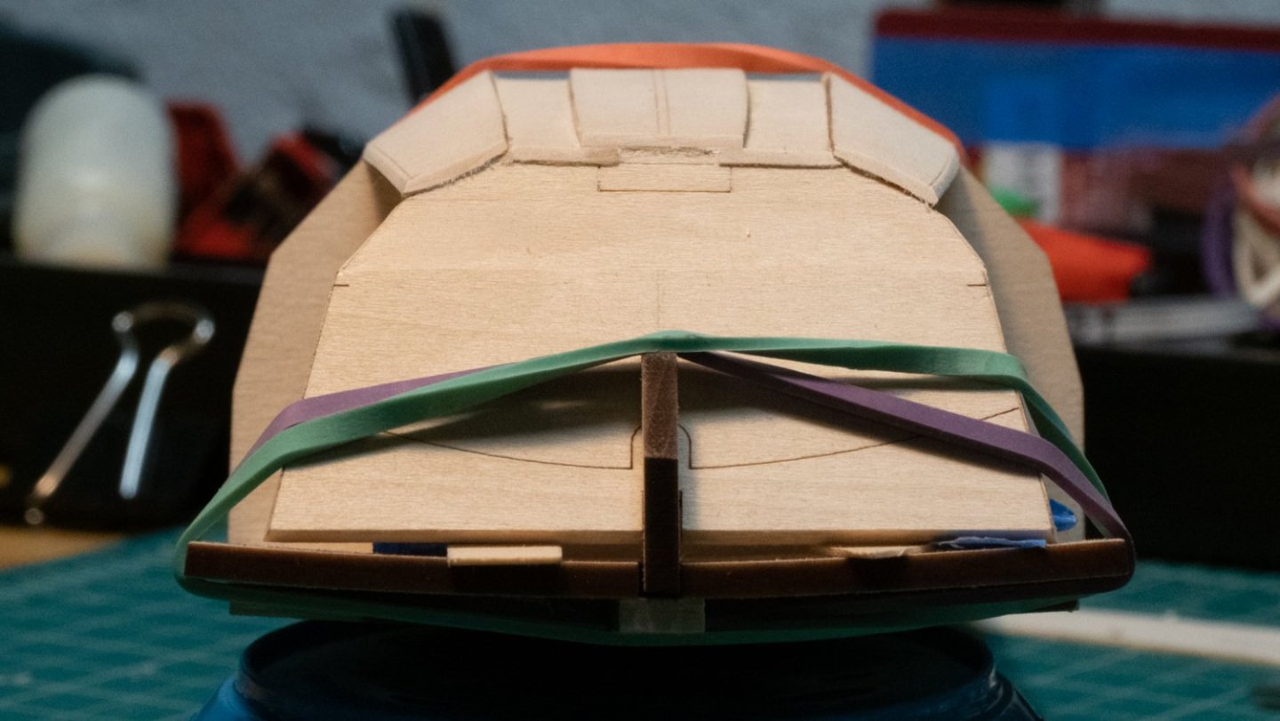
This week's update: Based on a warning from some other build logs, I checked the width of the chain plates before making the slots for them, and used the piece itself as a guide for how long to make the slot. I didn't have the small saw blade shown in the instructions, so used the pin vise drill to take out as much material as I could, and cleared out the rest with the tip of a #11 blade. For the rowlock pads, I didn't look closely enough at the instructions, which show them being shaped by a chisel while still attached to a longer piece of stock, which may have given me better results. I used a small piece of wood as a stop and a chisel to shape them after I had already cut them out. There are four rowlock pads, the instructions mention the fore two, but all the pictures have four. I placed them roughly where I thought they should go based on the pictures. Rub rails - these went on pretty easily. Gluing the top pieces to the dagger board. I tried to get the best 90 degree angle I could. I made the dagger board and the "lid" mentioned in the instructions. I tried to put some finger grips onto the lid piece after gluing it all together, and found it a struggle - I wasn't happy with what I ended up with. If I were to do this model again, I'd file/sand the finger grips into the pieces before gluing. It would have been a lot easier. As it is, I left the dagger board alone. To transfer the curve on one side of the rudder to the other, I used tracing paper, cut it out, and drew the curve on the other side. Sanding and filing was straightforward. The instructions say something about creating a notch between the two marks, but on the lower side of the rudder, there were three marks. After doing quite a bit of looking at other build logs, I made some rectangular notches. Most pictures of don't bring much detail. One of my "rectangular" notches is a little off, now that I look at this picture, so I will revisit it. In a previous update, I shared my approach to getting all the seats to be straight across/level with each other, and wondered whether this would be a good approach. As shown in this image from my last post, I used a flexible ruler as a guide to make them all level with one another. So was it a good approach? Yes and No, but closer to No. Two issues have arisen after taking this approach: The positions of the seats are ALSO dependent on the positions of other elements of the boat, such as the dagger board case The "level-ness" of the seats from port to starboard are also a consideration. For #1: The middle seat is perfectly aligned with the stern-most one - but the whole seat is too high to fit around the dagger board case. For #2: Port to starboard "level-ness" not quite there... I had tried to line things up when I first glued in the fore-most and aft-most frames, but still missed by a little. Neither of these are unfixable problems, I have some adjustments to make, then put on the midships thwart knees. Then - painting. I have spent some time on and off trying a painting technique to produce some basic lettering on the stern of my pram, based on an idea I found on this site. I have had mixed success so far, but it's promising. I'll post more in the future about it, regardless of whether it works out or not. Below is a fairly successful attempt.

-
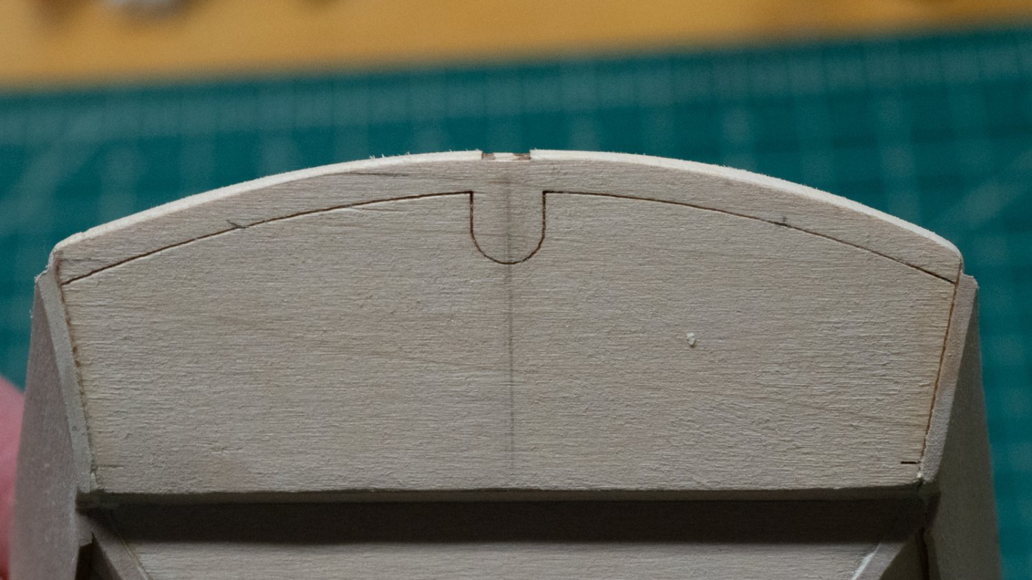
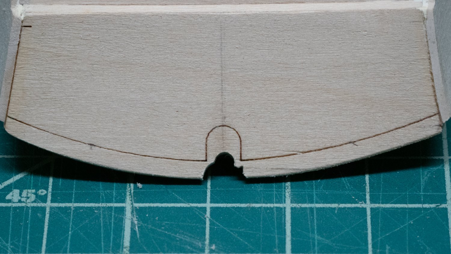
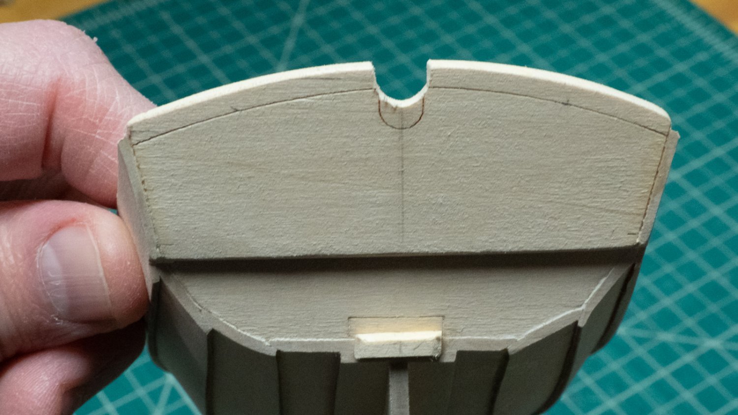
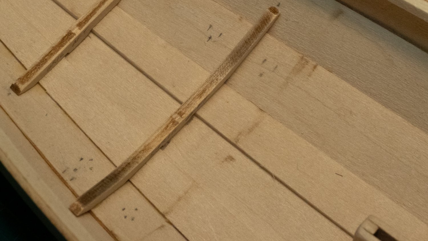
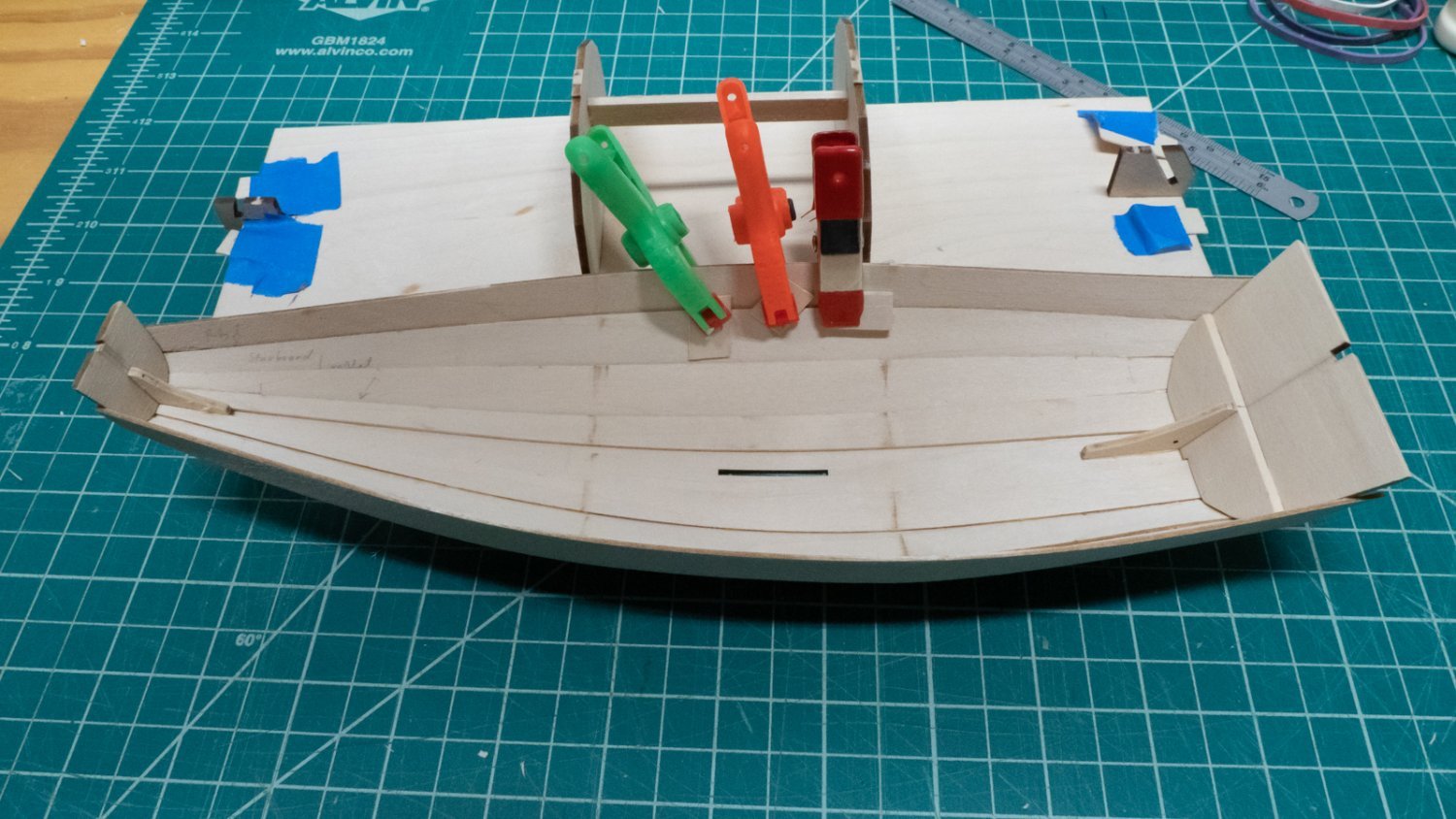
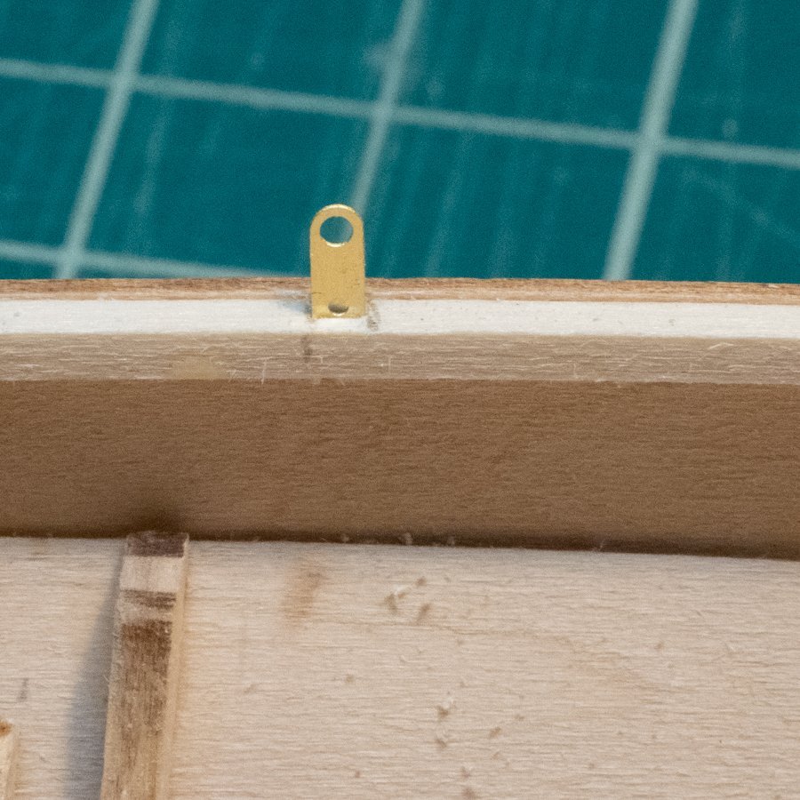
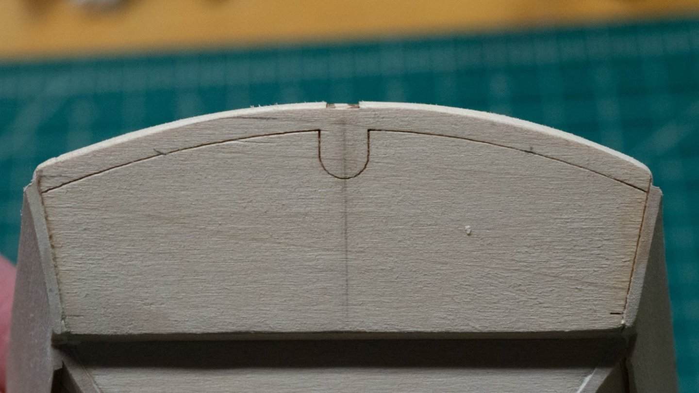
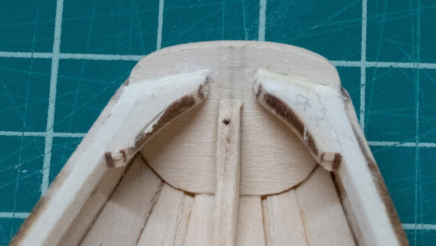
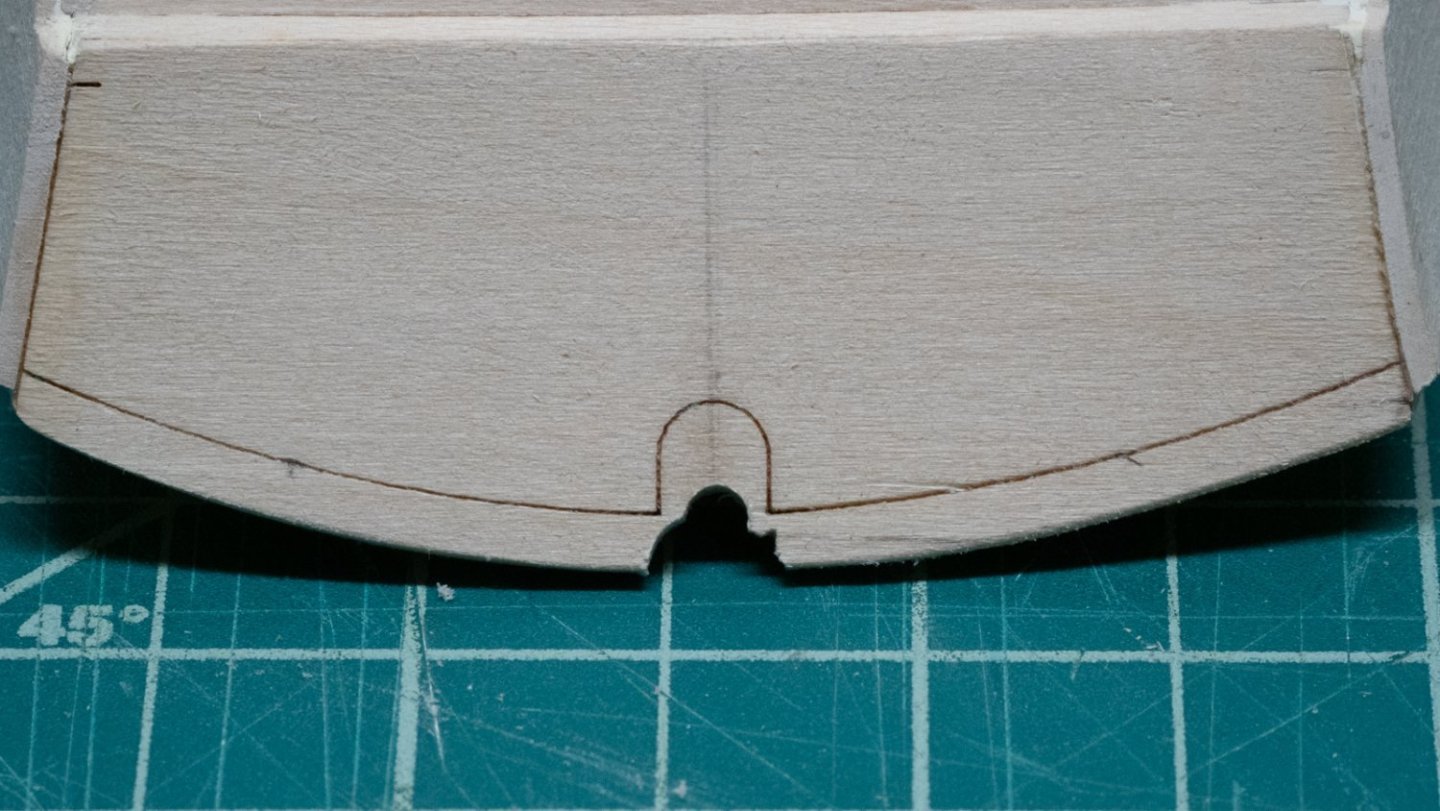
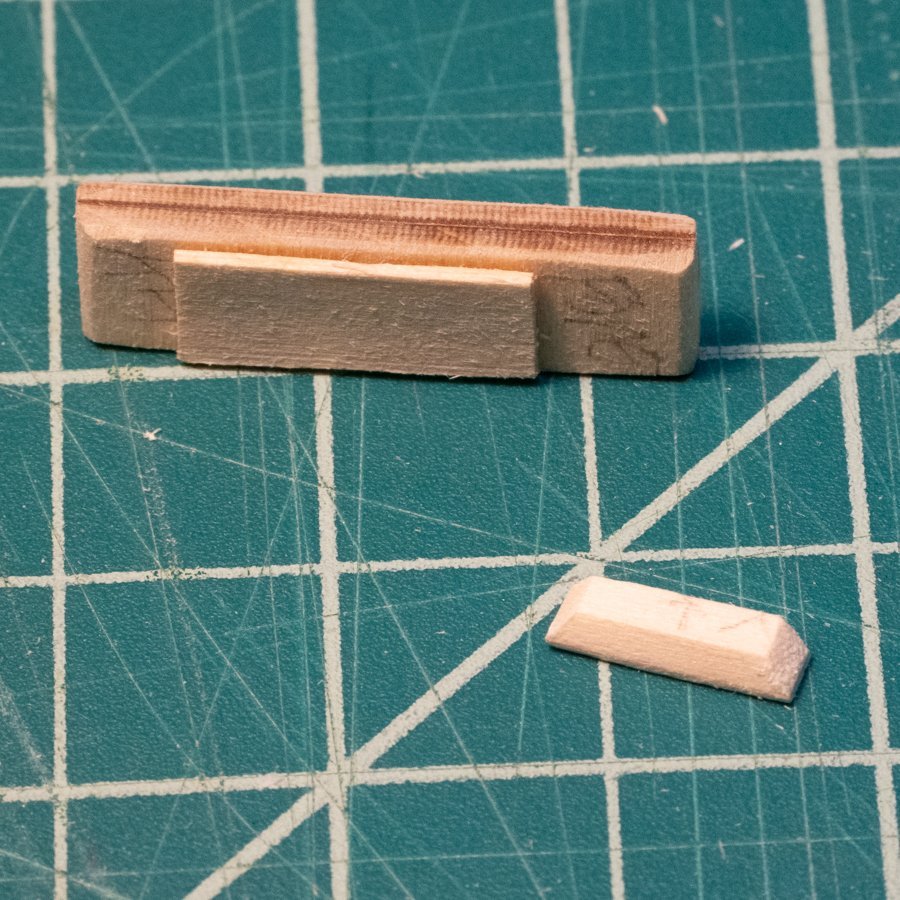
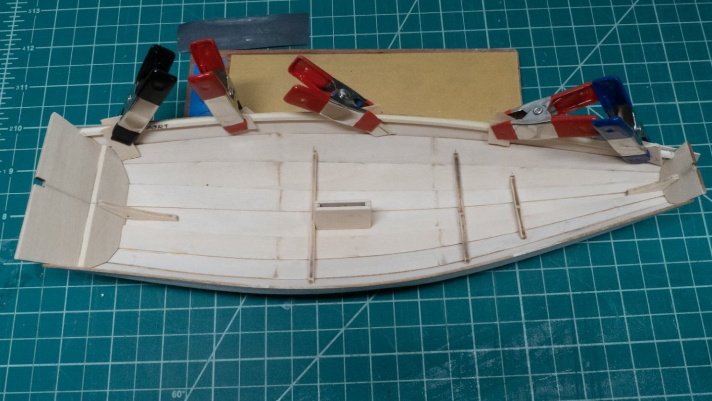
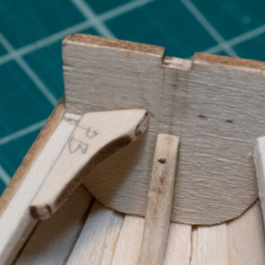
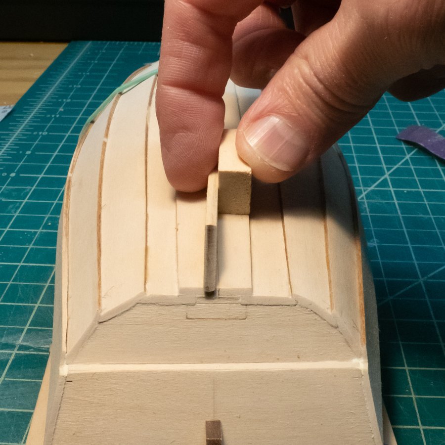
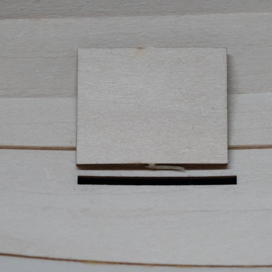
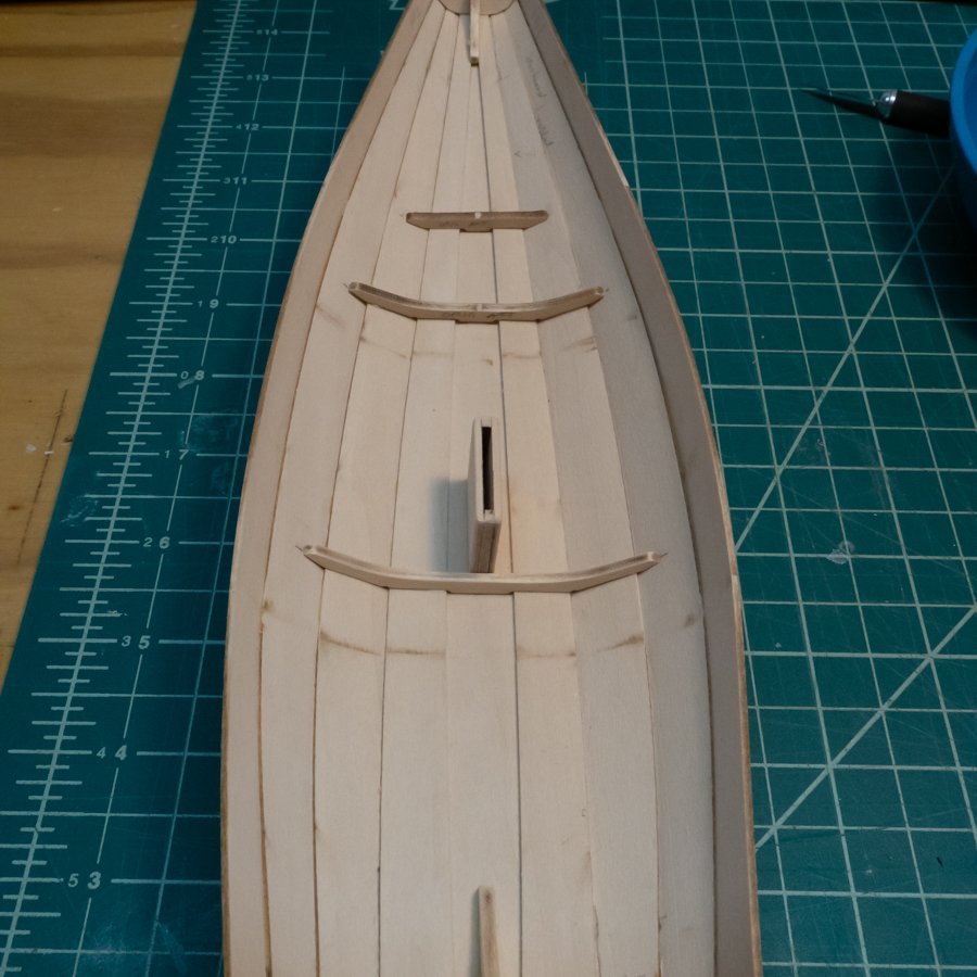
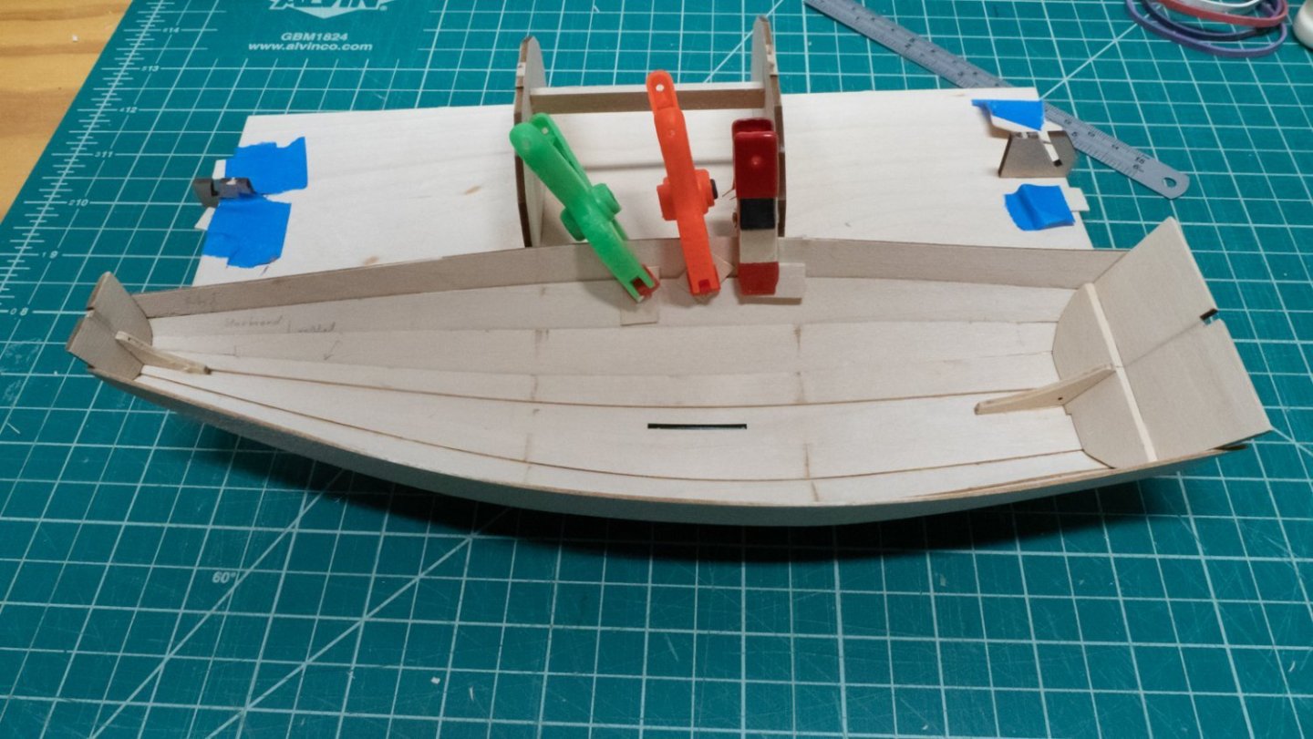
Back after a few weeks of diversions... Nothing new or ground-breaking in these last steps. In order to make sure the seat frames were going to line up with the seats on them, and to make them straight from fore to aft, I clipped a flexible ruler across the tops of the aft-most and fore-most frames. I then snugged each subsequent frame up against the ruler so the seats will line up. I hope this works out like I think it will. For the cleats, I tried to bend them after soaking them in hot water - they really didn't want to bend, see the pile of stuff I used to try to bend them. I tried again, still no luck. I decided to just hold them down while gluing them, which worked well enough. I marked the stern and bow transoms to trim the excess of both. I used a cheap compass as a marking tool, running the point along the marked line. I used an xacto saw blade to cut some of the excess, then a sanding stick for the rest. I didn't have the right size of file for the notch in the stern transom (although 3/8" noted in the instructions seems awfully big), so I used sandpaper around a paint brush handle. I managed to snap off a tiny piece of material, but managed to sand it so it doesn't look bad. It's better than it looks in the picture. The rudder gudgeon pad and the mast step were pretty straightforward - I glued an extra piece under the two provided pieces to create the "stop" mentioned in the instructions. As others noted, the instructions indicate that only one of these pieces has a hole, when both do. So far, so good.

-
This is really nice - my favorite Dory so far.
- 39 replies
-
- 1
-
-
- Lowell Grand Banks Dory
- Model Shipways
- (and 1 more)
-
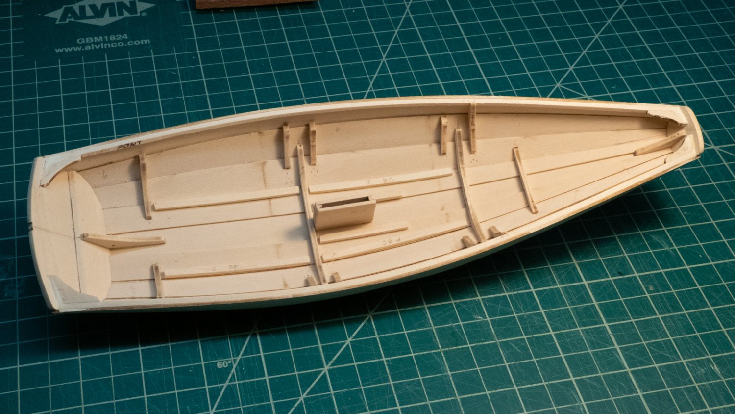
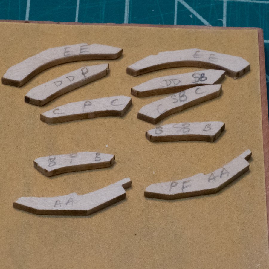
This week's update: I bent and glued the inwales on both sides. There were a few tiny gaps at the bow that needed some filler. I wish I had thought of bending them on the outside like @MajorChaos did here. I filled the gap in the keel plank aft of the dagger board case and sanded/filed it down. I cut out the stern and bow quarter knees, and sanded them so they fit on their respective transoms and inwales. I didn't feel like gluing yet, so I removed all the seat and thwart frames, and sanded the char off. A few days later, I was in the mood to glue, and attached the bow and stern quarter knees. I needed a tiny bit of filler here, and filled it in when the glue was dry. Next, I started shaping the "A" thwart frames. I wanted them to sit parallel to the nearby frame, so I sanded them that way. Using the paper guides, I made some dots to help line up the frames when gluing - two dots for the sides, and a dot for the middle. Some frames got more than one set of marks. After gluing them, keeping them parallel to the bottom frame, I realized how far off "vertical" the bottom frame was, and how following its lines, the "A" frames were also way off vertical. I removed the bottom frame and thwart frames by carefully putting some water on them, and reshaped the bottom frame so it would fit vertically this time. I glued it, then reshaped the "A" thwart frames to be parallel, and glued those. They look much better. Following some other build logs, and observing how others were fitting the thwart frames, was helpful in deciding the next steps. The seats need to be straight across from fore to aft, and you can't just glue the thwart frames arbitrarily and expect that to work. I first thought I would glue A and B, then find the "level" on those, and transfer that straight to the stern. After looking at things with the A frames in, I thought it would be easier if I put in the E frames (at the stern) next, then use the line between A and E frames to define the "plane" for the thwarts. I glued the first E frame in, and noticed it was not perpendicular to the stern knee, so I took it off before the glue dried. I sanded and glued the other one, making sure it was perpendicular. Then back to the first one after it dried. They are very close to perpendicular, not perfect, but close enough. A lot of ungluing, regluing, and filling this week, two steps forward and one step back, but that's OK - I didn't have any major problems that weren't easily solved. Due to work and other commitments, I probably won't make progress next week on this. When I do get back to things, it will resume with fitting and gluing the B, C, and D thwart frames.


-
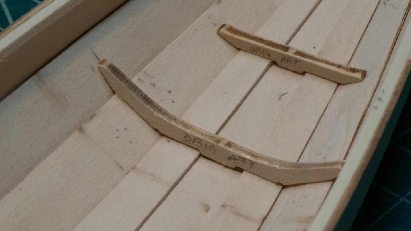
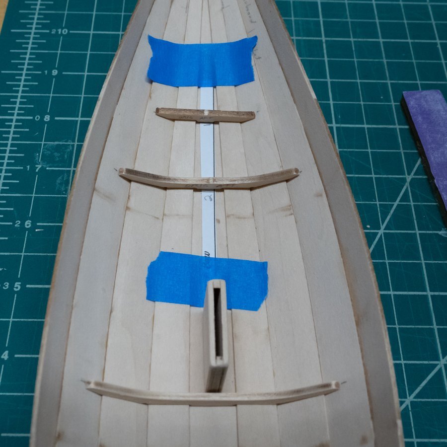
@MajorChaos you've given me a good heads-up here. I am working through the steps you've just completed, and have wondered how to ensure that everything is sitting properly. I like the idea of prepping the thwarts (or copies of them) and using them as guides. I had considered putting some blue tape or paper or something where I think the thwarts should sit, and then using that as a guide for shaping and gluing. It looks from many pictures I can find that if you put a straightedge from fore to aft on top of the thwarts, they will all line up. If that's the case (and I'm not positive), starting with one and then working aft might be a good approach. Do the A/B thwart first, then the C/D thwart, using the A/B thwart as the guide.
- 72 replies
-
- 1
-
-
- Norwegian Sailing Pram
- Model Shipways
- (and 1 more)
-
Looking good! I like the text you add to your photos. I'm following...
- 21 replies
-
- 3
-
-
-
- Norwegian Sailing Pram
- Model Shipways
- (and 1 more)
-
Oh, you're bending! Good idea, and so obvious now that I've seen it. I wish I had seen your log before I did mine... 😀
- 72 replies
-
- 3
-
-
- Norwegian Sailing Pram
- Model Shipways
- (and 1 more)
-
@MajorChaos the inwales go on the inside of the sheer strakes. I just did this step, and the gluing was a challenge for me as it has been for all the long pieces.
- 72 replies
-
- 1
-
-
- Norwegian Sailing Pram
- Model Shipways
- (and 1 more)
-
Oh really? It looks like you're farther along than I am, and have been for a while... 😀
-
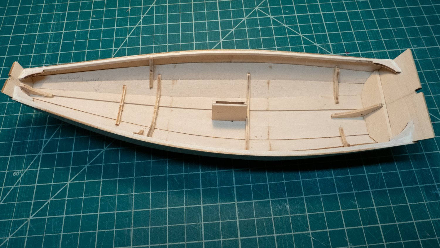
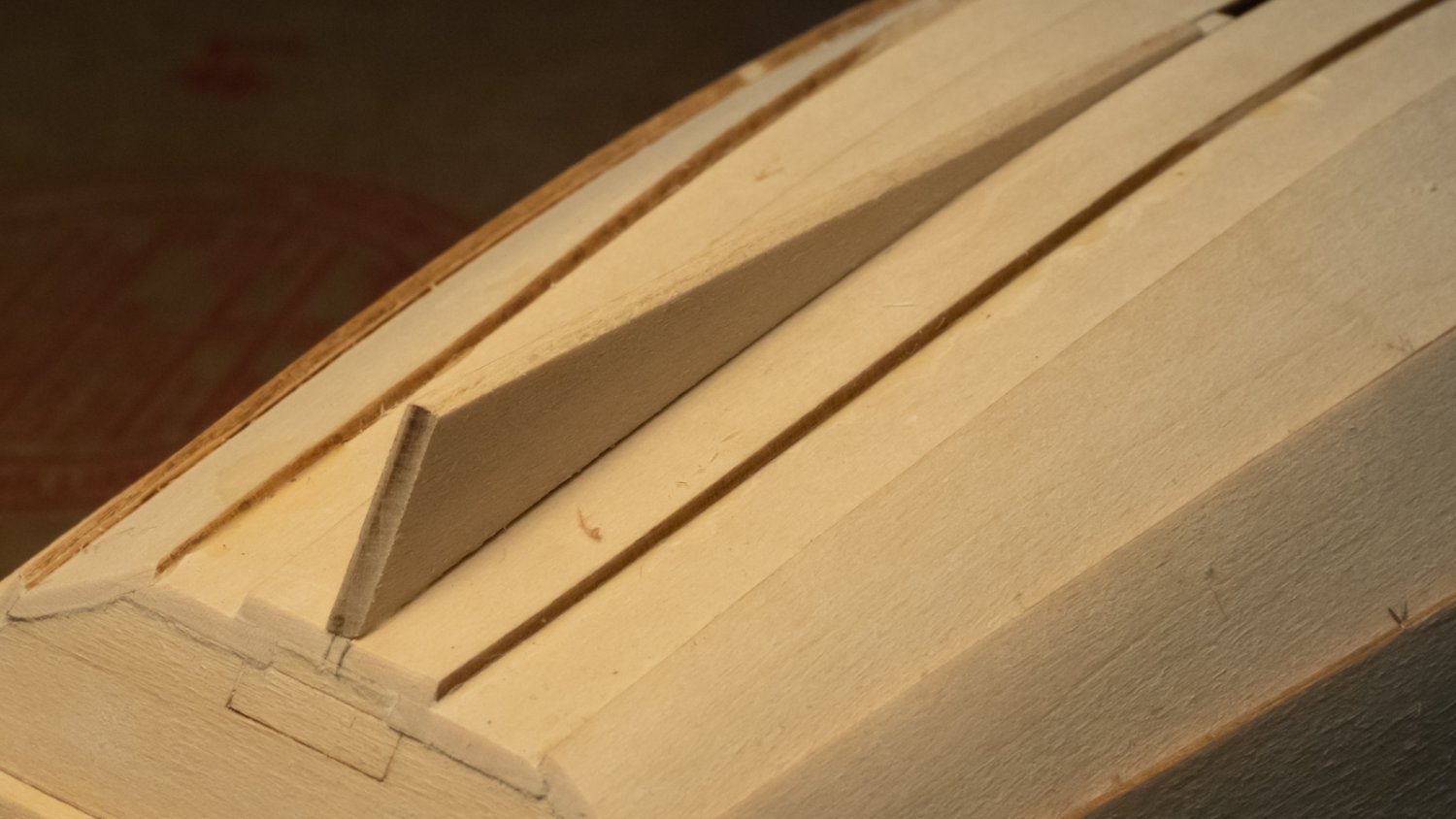
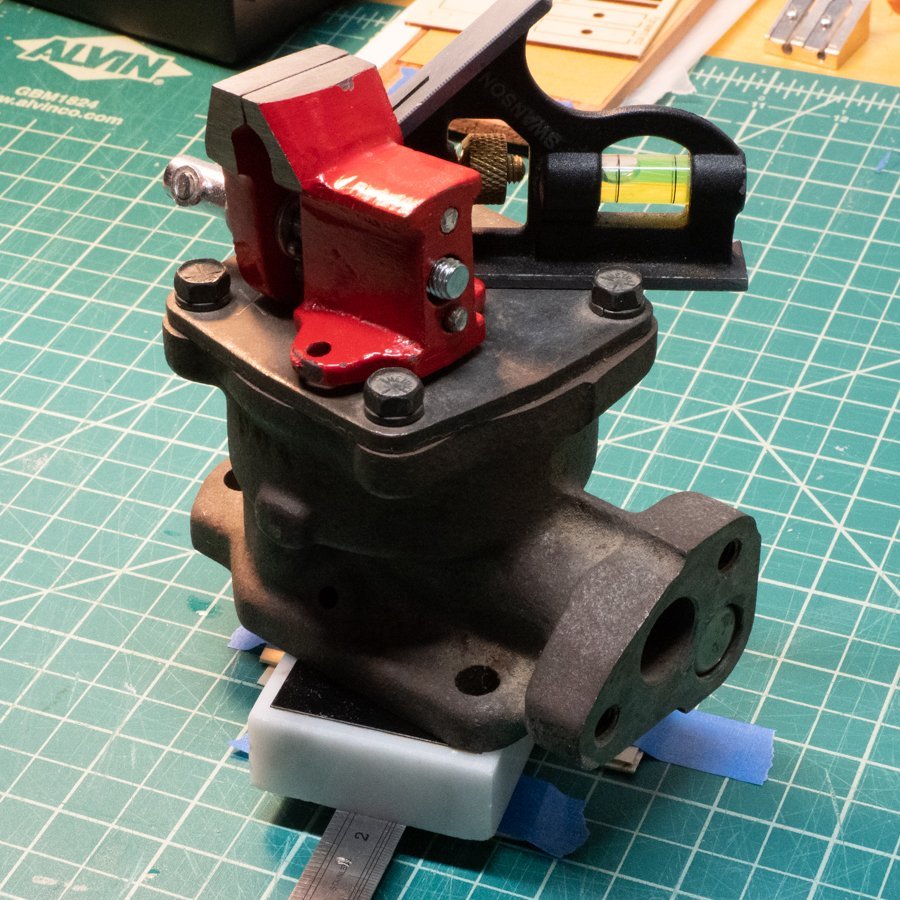
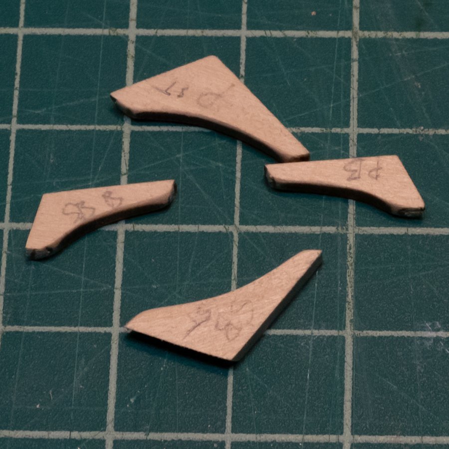
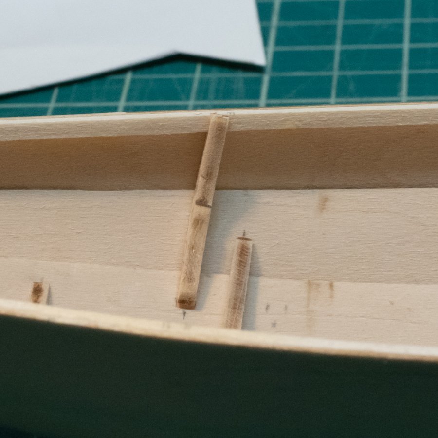
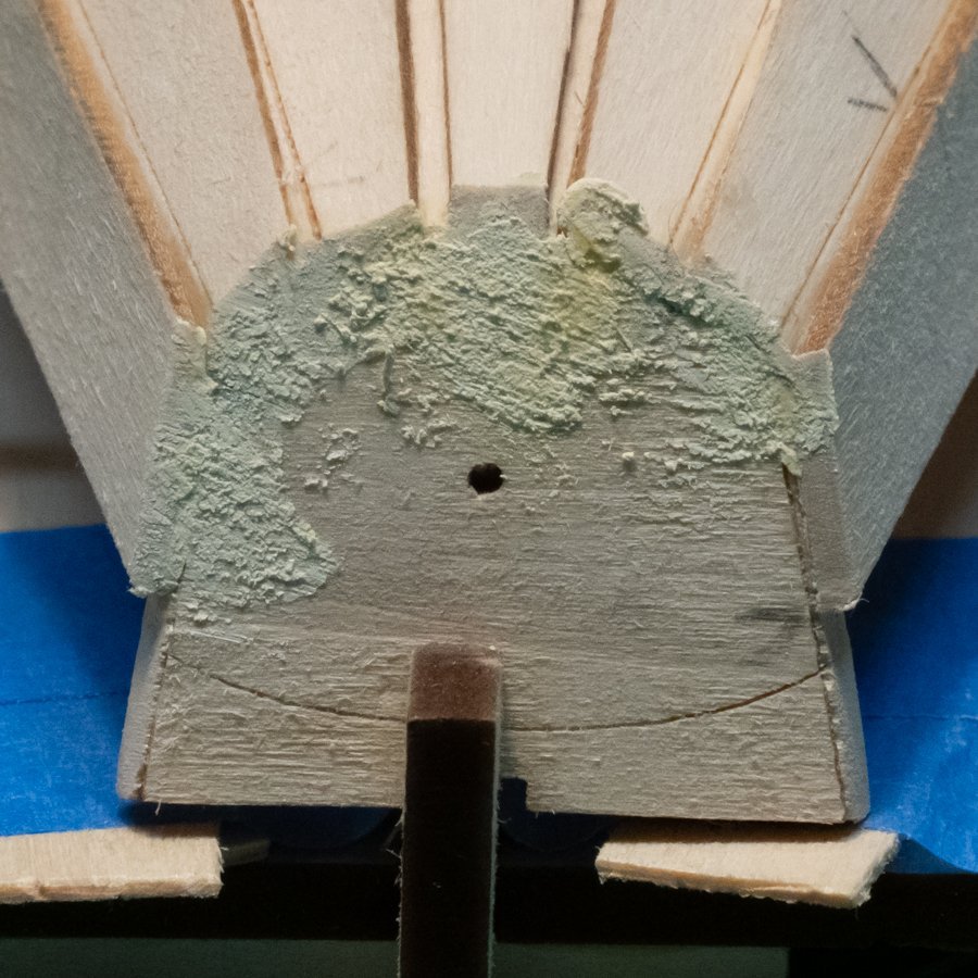
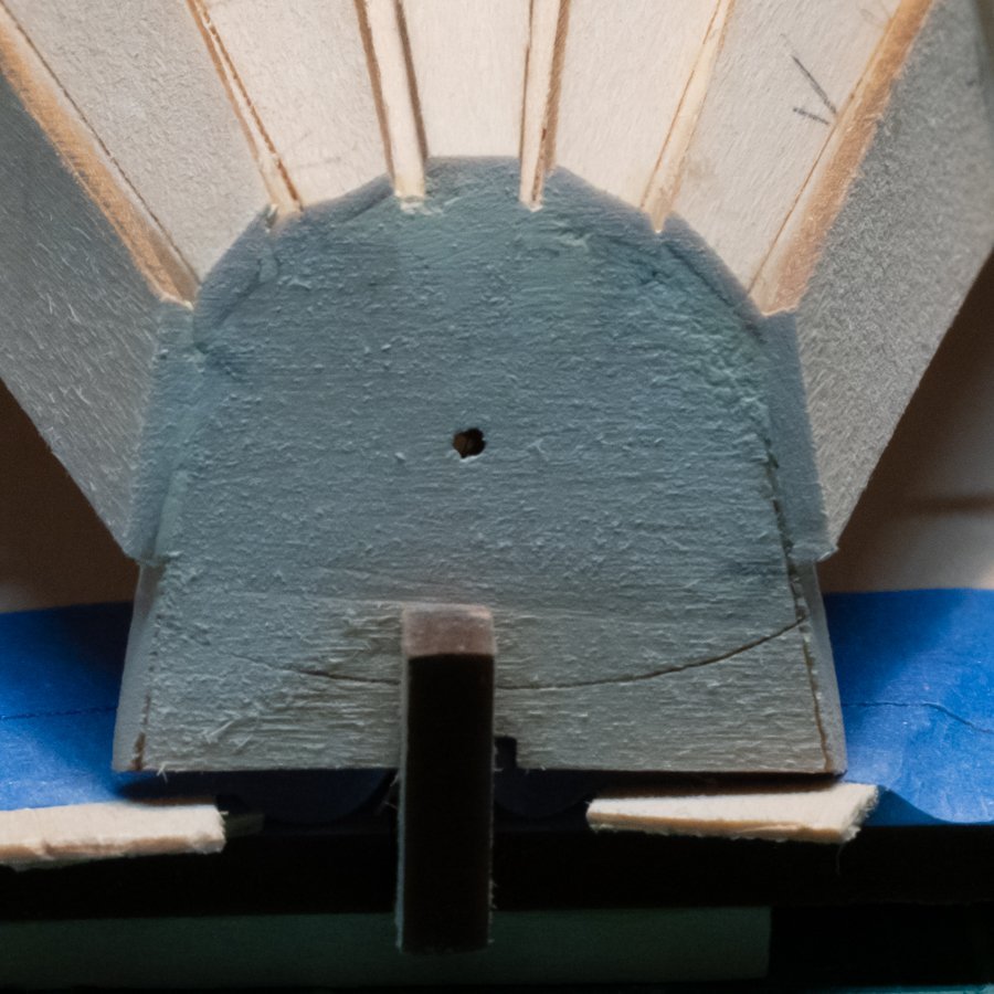
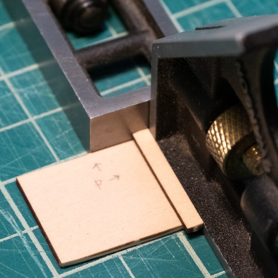
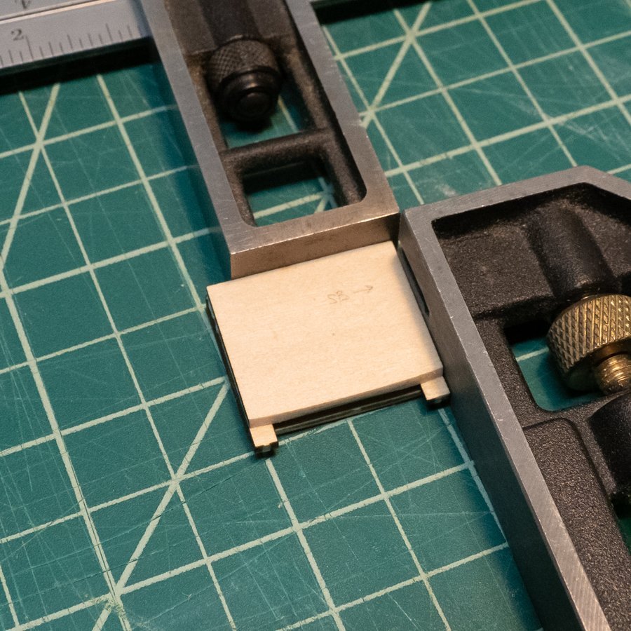
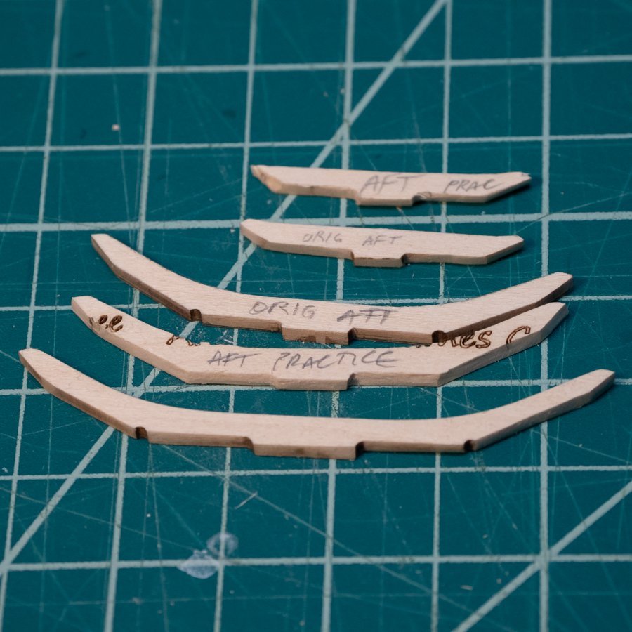
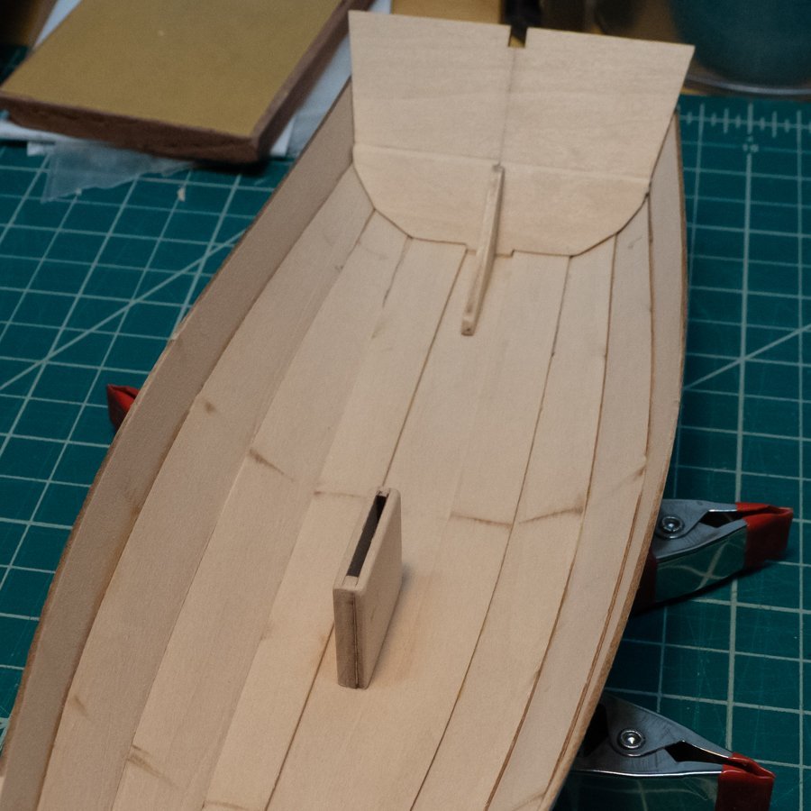
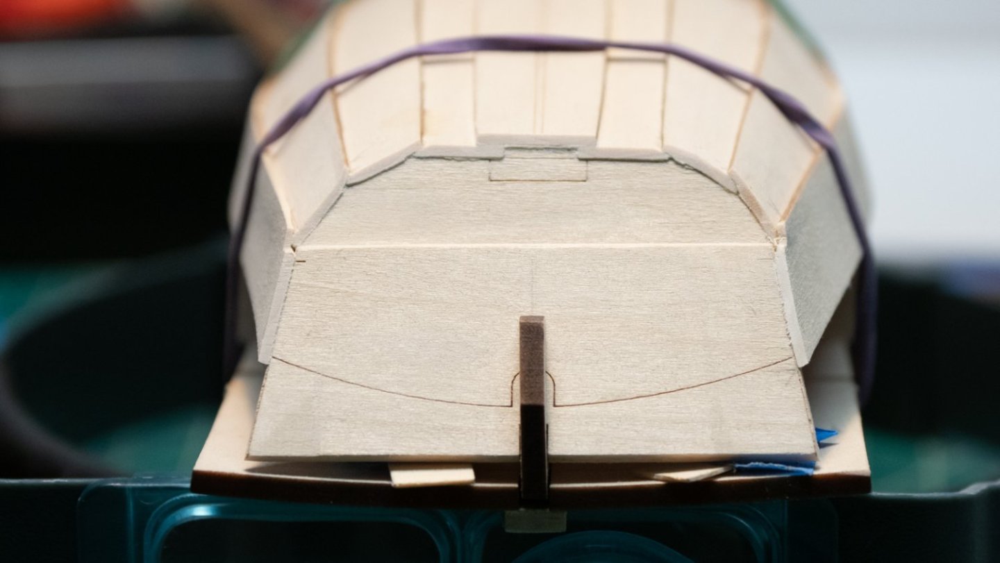
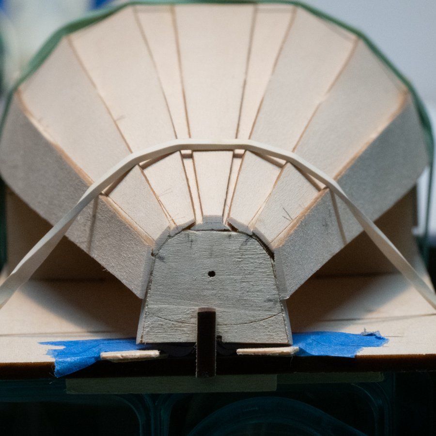
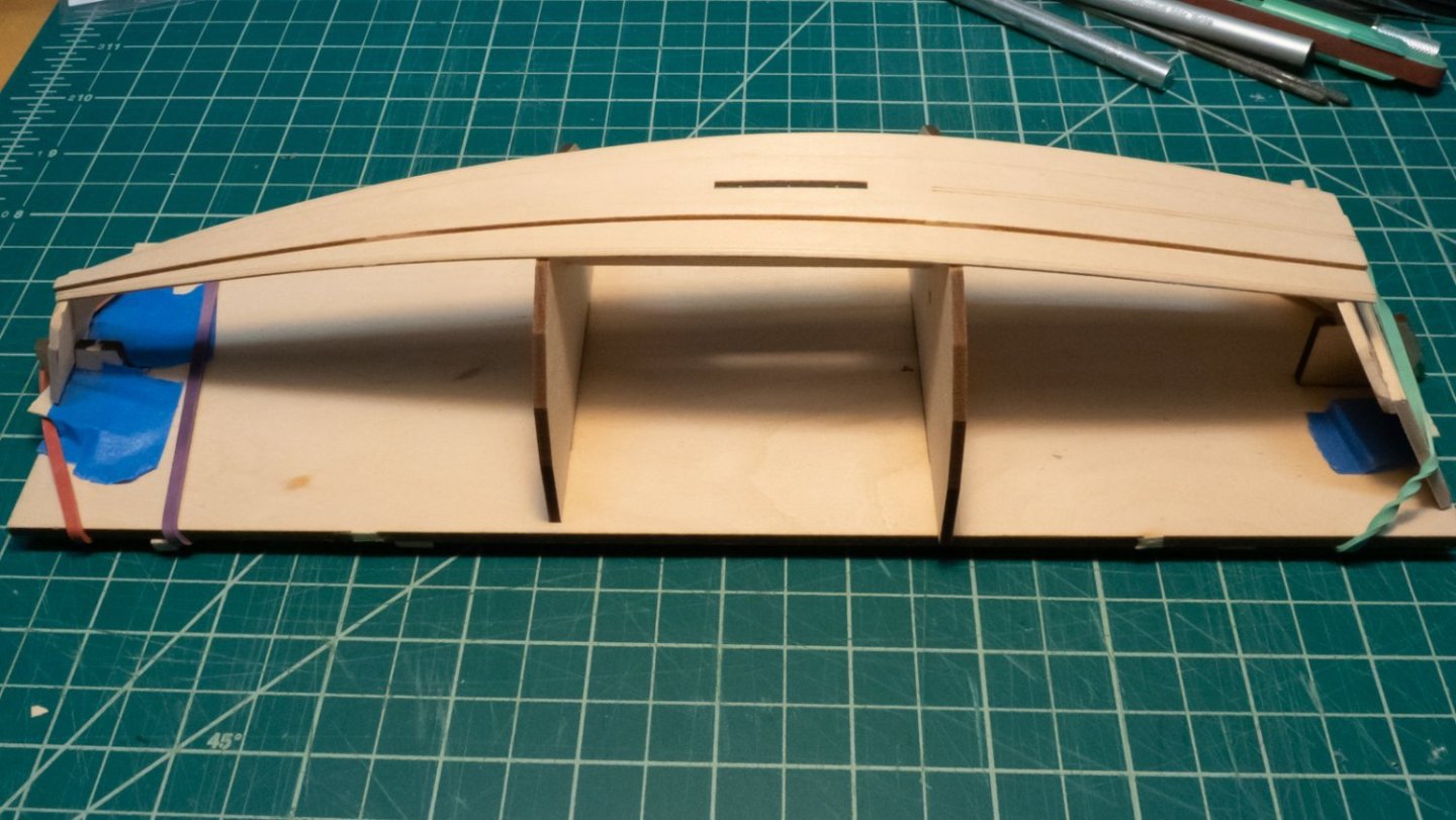
There's not a lot of noticeable progress this week, but I was able to complete some important steps and trials that will help in future steps. After planking was done, I had some filling to do, at both bow and stern. On a recommendation on this forum, I bought some Durham's Water Putty, in stock at my local Home Depot. It's a powder that's mixed with water, and getting the right consistency took a few tries. I spread it on some scrap pieces of wood glued together to test it out. After sanding and filing it down to understand how it would respond, I was ready to put some on the model. First, a tiny dab on the stern transom/plank joints. These holes were so small that paint may have been enough to "fill" them but I wanted to work up to the larger gaps at the bow. A small square file was used to reduce the dry filler to the right shape. For the bow, I put a little extra over the gaps, and when it was dry, sanded down flush with the bow transom. The filler sanded to a dust, and was easy to smooth out. On to the skeg and bilge keels: I sanded the skeg against the keel plank's curve, but didn't rubber-cement it. I made some marks to center it while gluing. I held a small block of wood next to it to help keep it straight during gluing, and held it with my hand for 5 minutes until the glue was set. I sanded the bilge keels on their bottom planks the same way. For gluing, I put some blocks next to the edge of the planks at either end so I could register the ends of the bilge keels to them while holding down the whole thing with my fingers. I didn't get a photo of the bottom after all were glued... The dagger board case was straightforward as shown in the instructions. I sanded the curves on the bottoms the same way as the skeg and bilge keels, with markings on the pieces to keep them straight. As others have noted, the length of the case was shorter than the provided slot in the keel. I used two straight-edged surfaces to square up the parts of the case while gluing, and pressed the parts against them (and held them steady) with my fingers. Then I sanded the edges around everything except the parts that extend through the keel plank. Once it was assembled, and before gluing, I considered three ways to fill the gap: Cut out a piece of scrap that's the same thickness as the keel plank and glue it in Cut out a piece of scrap that's thicker than the keel plank, glue it in, then sand it flush Wait until the dagger board case is glued, and use wood filler. I tried options 1 and 2 without gluing; both probably would have worked, but the gap is really small, and it was hard to handle a piece of scrap 1/16" x 3/64", even with tweezers and an optivisor. Looking ahead in the instructions, I saw that one of the frames was glued flush with the aft end of the dagger board case, covering the "top" of the gap, and the Option 3 rose to the top as the best possible solution. I glued the case in, and left the filling for after the frames are in. The bottom frames were one of those steps that looks simple at first glance, but have some complications. The frame behind the dagger board case fit perfectly on the port side, but was slightly long on the starboard side; some shaping helped it fit better. The two fore frames need to be shaped to the planks, and beveled so they sit "vertical". If not beveled, they lean aft, and the instructions indicate these should be vertical. I was nervous about ruining the originals from the parts board, so I cut out some close duplicates and sanded away on those until I had something I was happy with. Then it was a matter of duplicating the sanding on the originals. This took quite a bit of time but was worth it. After making some marks where the frames meet the keel plank and the side planks, I glued all three frames, lining them up with the marks and holding them with my thumbs for 4-5 minutes. After gluing, I measured and found the two fore frames a tiny bit shy of parallel but I don't think it will be noticeable. It's better than it looks in the photo above. Next: filling the gap behind the dagger board case and inwales.

-
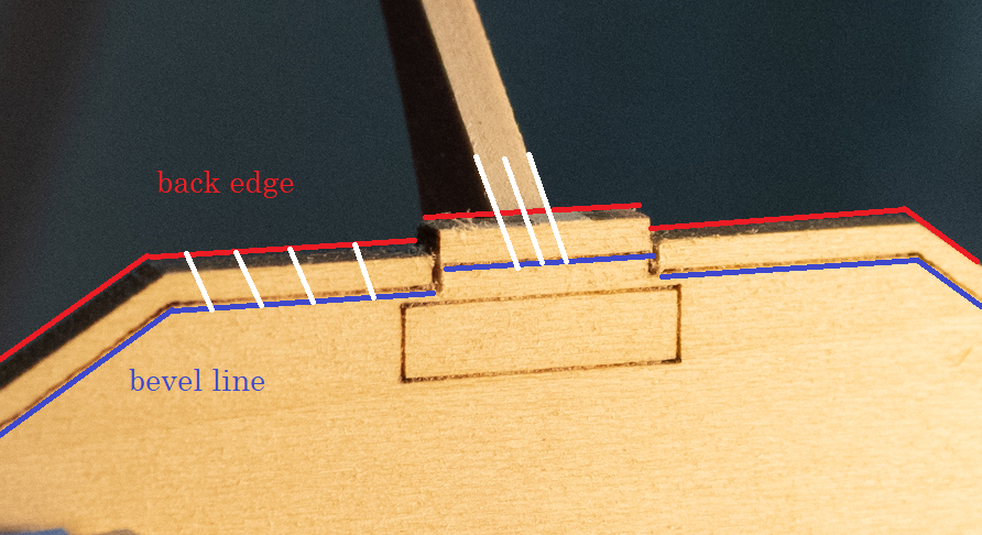
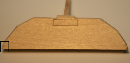
I think I understand your question. I glued the knee onto the lower transom before the steps you're asking about. It's earlier in the build log. At the step you're asking about, you want to sand from the back edge of the charred surface down to the laser line. In this screen shot, the back edge is red and the bevel (laser) line is blue - I hope you can see the colors. I started with the knee, and sanded the back edge to the bevel line at the same angle as the knee connects to the transom. Hold a sanding stick parallel to the knee, and sand until you've beveled down to where the sanding stick is basically touching the knee. If done right, the bevel line should just disappear. You should be able to hold up a straight edge on the knee, and have a straight line from the far end of the knee to the near surface of the lower transom. I then beveled the remaining edges the same way - sand between the back edge and the bevel line until you've just reached the back edge (char is now fully gone) and the bevel line has just disappeared. The only part you don't sand like this on the lower transom piece is the last 1/8" inch - this will be beveled later after the transom pieces are glued together. I'm referring to the parts below with squares around them - don't sand the bevel there. I hope that helps.
-
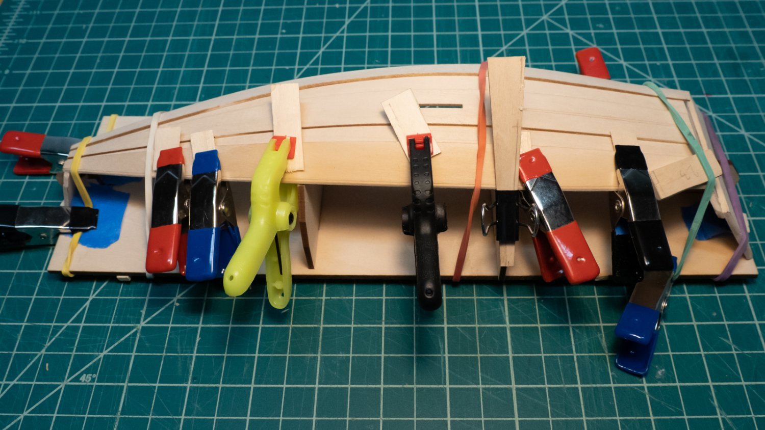
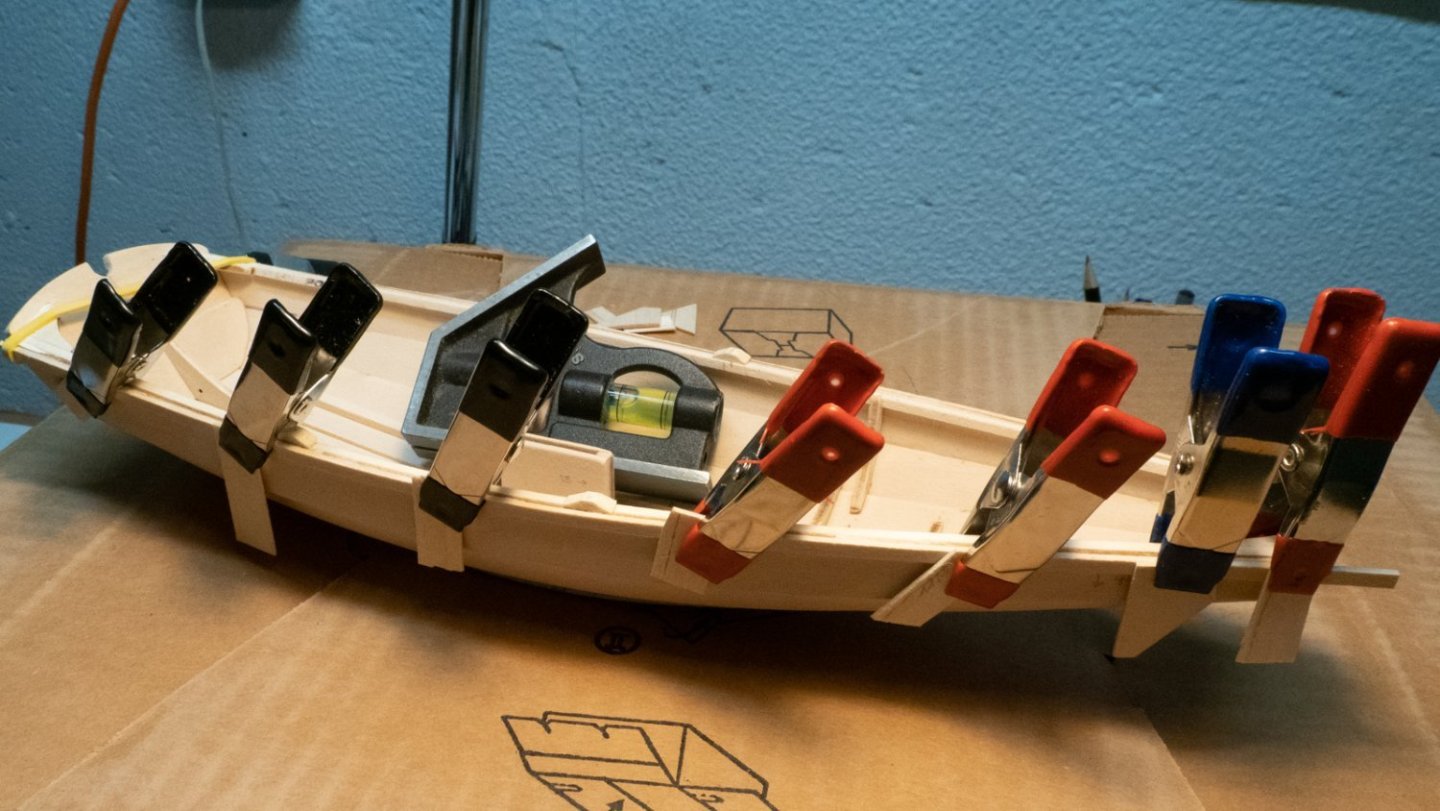
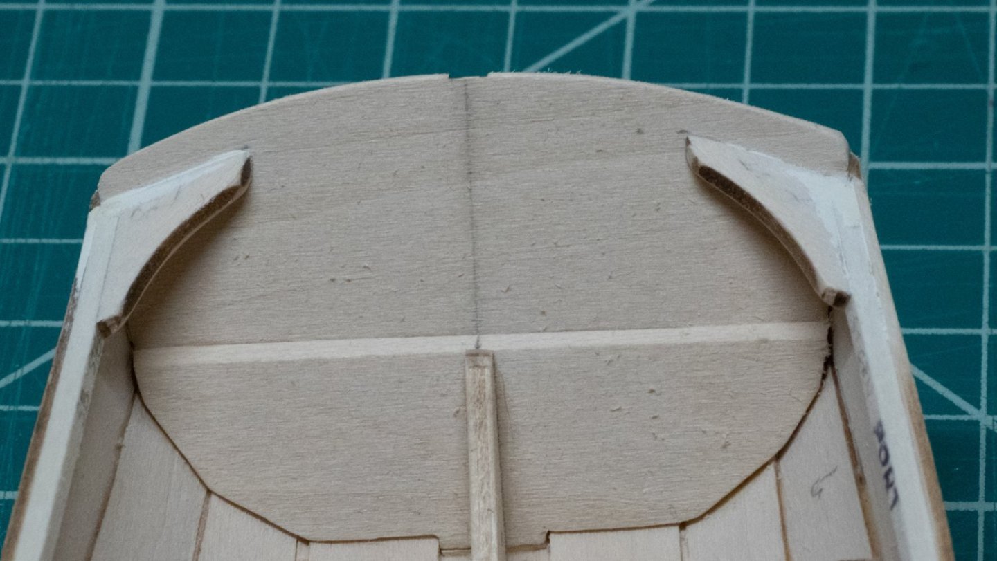
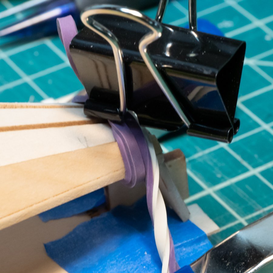
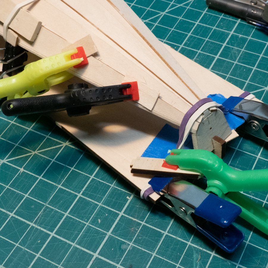
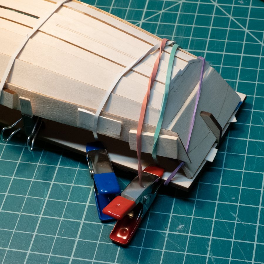
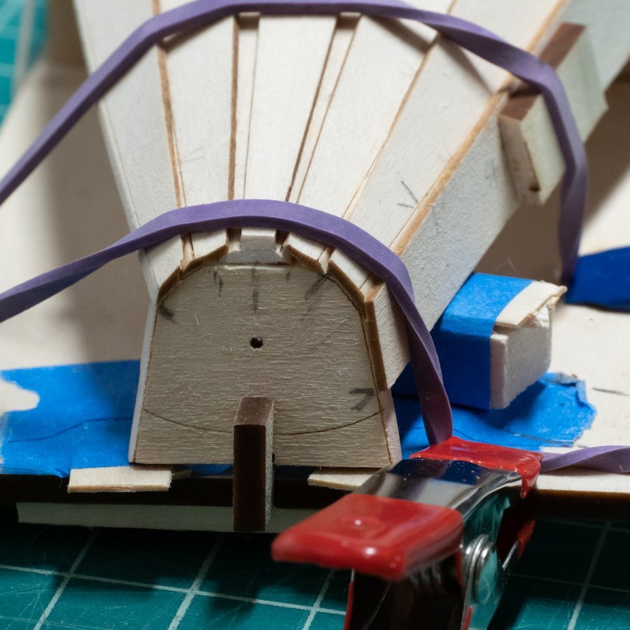
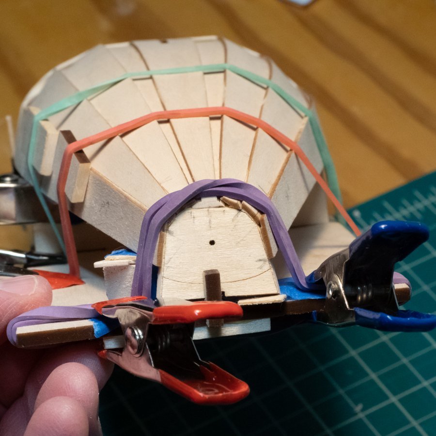
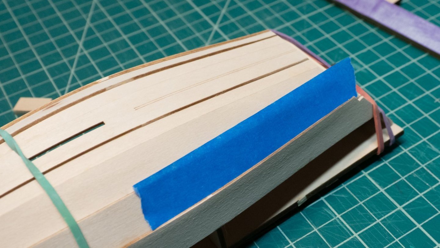
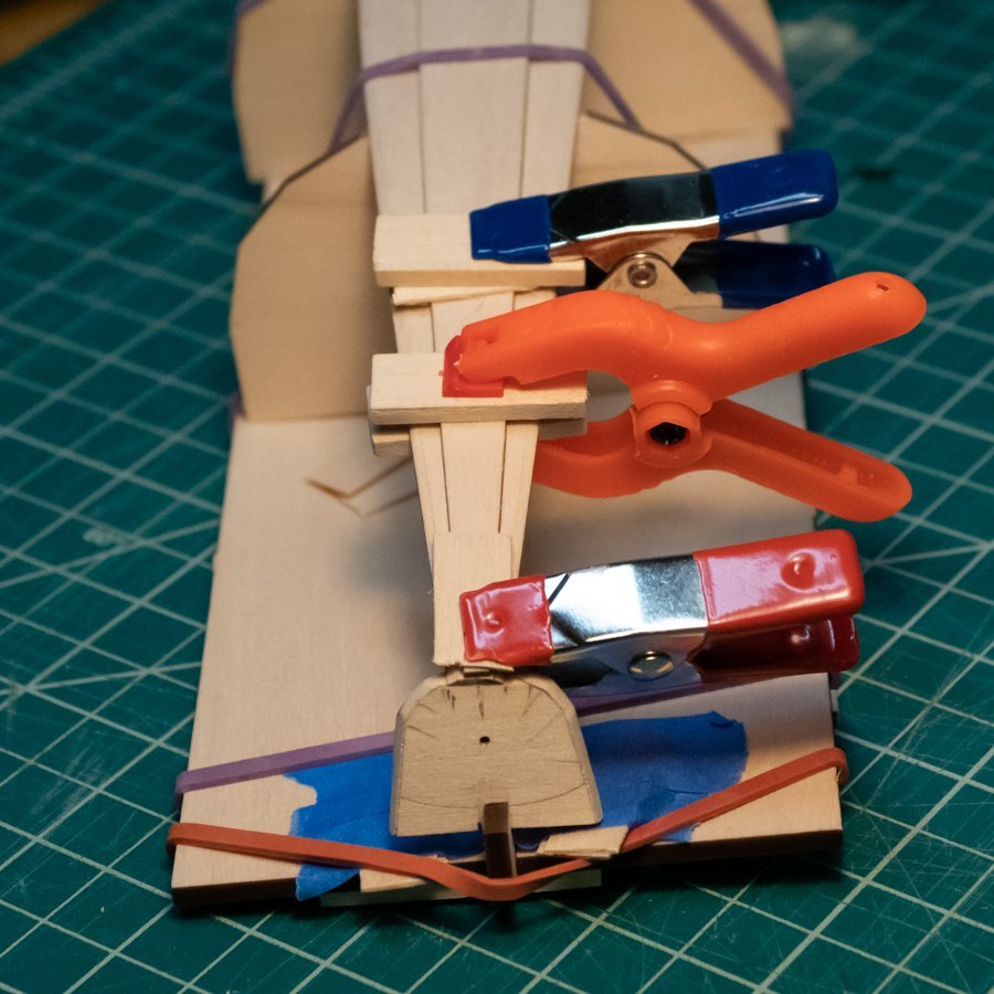
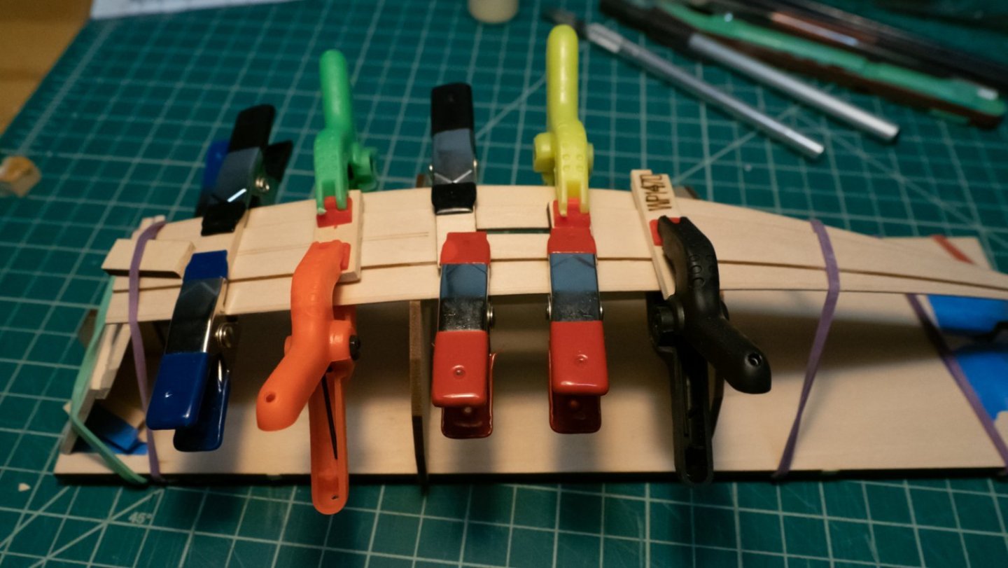
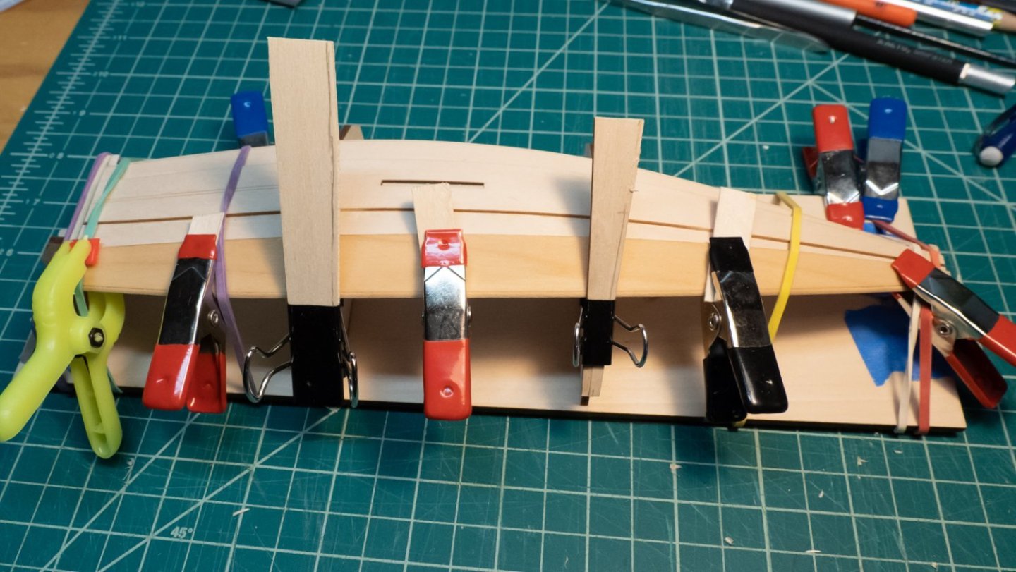
Moving on with gluing more planks: In general, I had issues with rabbets fitting snugly onto the preceding planks; the rectangular shapes weren't working well for me. I tried out test rabbets/bevels on scrap pieces of wood, then took the approach that fit with the actual plank. The bow planks fit pretty poorly onto each other; the stern planks are better, but still some room for improvement. The photos at the end of this post show the gaps at the bow. When gluing the garboards, I wanted to pull down with rubber bands during clamping, while ensuring the plank itself wasn't pulled downward. I wrapped a rubber band around them and clipped it at the top to keep it in place. For future gluings, I found it easier to hold the bow ends with my fingers for 5-10 minutes until it dried, so I was able to abandon this approach. There's no new ground to cover for bending and gluing the planks, since most build logs have pictures. Below are a few photos as things were progressing. A common pattern for me was a rubber band around the whole model, a flat piece of scrap on top of the plank, and a clip to pull the rubber band tighter against the building board. Clips worked pretty well on the earlier planks, but weren't helpful for the sheer plank. To keep the sheer plank in place, I made a small block to put under the plank so it wouldn't shift down while the glue dried. I used the same block on the other side as well. During gluing, I misplaced planks twice - before they completely dried, I drizzled water into the joint to free it and then reglued it. It was worth it to redo them. It was hard to know for sure how to place each plank, and my results were: The bow end of the planks ended up short of the drawn line The stern end of the planks ended up past the drawn line. I am not sure how to have determined these mis-measurements ahead of time. I don't think either will have a large impact on any of the future steps, and hopefully I can sand and shape the transoms to look good enough. My hat is off to those builders whose planks lined up the right way at both ends! 🎩 I cut out the extra material from both sheer planks where they transition from the lower to the upper stern transoms, first with an x-acto saw blade, then with some sandpaper. I could see one small seam that was letting light through, so I put a little glue in and clipped it while inspecting the inside of the boat for the first time. It looks really good in there. Now it was time to do the final sanding at the transoms, some of which I've been putting off until all the planks were glued. I can see some light through the gaps at the bow, and there is just a little to do at the stern. Once sanded, I inspected it again, and I noticed that one of the sheer planks had a little too much material overlapping the adjacent plank. I masked off the adjacent plank with tape (there was a nice gap to slide the tape into!), and very lightly sanded it down with a sanding stick. Just a little past the char was sufficient; it looks better, and now it doesn't bother me when I look at it. Overall, I'm pleased with the planking, and I'm pleased to be at this stage of the build. Stern: Not bad Bow (Some gaps here to deal with, fitting the rabbets was a struggle...) Next: filler, and post-planking steps.
-
Many new builders here have started with the three-model Model Shipways series. There are many build logs for these models as well on this site. Each model is also available for sale separately, as are the paints, etc.
-
Looks great!
-
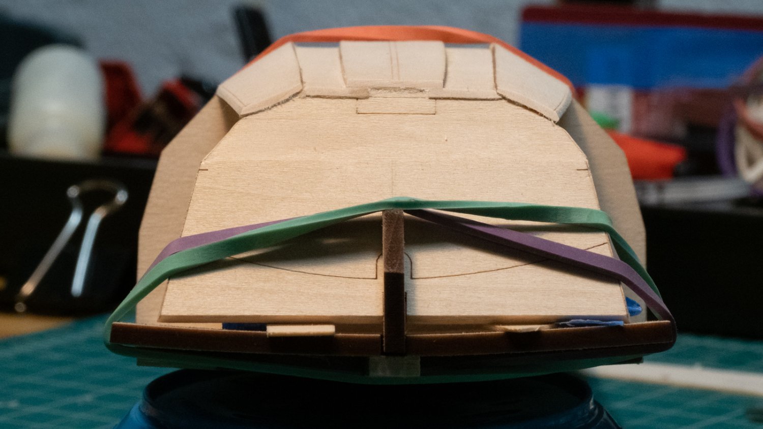
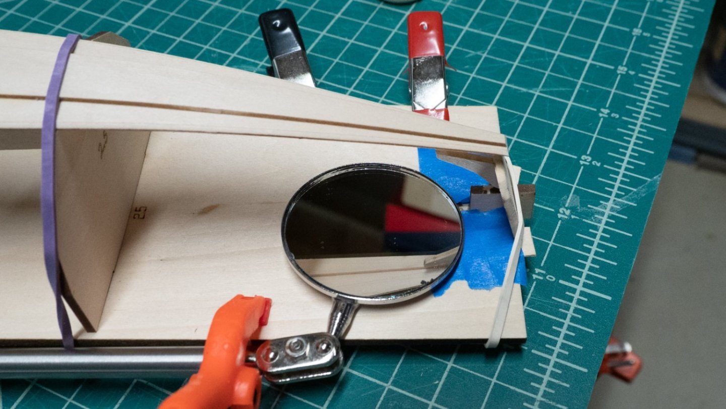
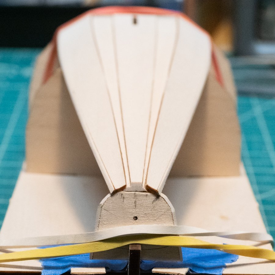
Some setbacks and a little progress on the pram this week... I glued on the keel plank - really straightforward. It's easy to see if it's centered by sighting down the middle. Bow, then stern. I sanded the extra plank material at the bow and stern transoms, leaving a tiny bit to be finished later. I prepped to bend the first garboard plank, and put too much pressure on the bow and broke the transom and planks apart. Ack. To glue it back together, I needed to make sure the knee was centered under the planks, and make sure the planks hit the transom at the right angle. It's not possible to see above and below the planks at the same time without... some help. It took a few sessions of dead-end ideas, and a long walk outside, to think of using a mirror underneath. The re-gluing worked well, thanks to the mirror. A backup idea was to use my phone's selfie camera to project the "view" underneath the planks and help locate the knee. On to the garboards: I cut them out and sanded the bevels. For the rabbets, I did the bow rabbets first, leaving the stern rabbets until after bending so I could see where the stern transom was going to meet the plank. I recommend not cutting rabbets according to the instructions, but rather trying some rabbets on scrap wood to see what fits. I followed the instructions (at least how I interpreted them), and ended up taking too much material out. When I do the final "finish" sanding I'll see if this needs filler - it probably will. I bent the planks (5-minute soak in hot water). The curve of the planks matched pretty well with the bottom planks, thank goodness. After bending the planks, I marked where the stern transom meets the garboard planks, and cut them shorter so I could put the rabbet in the right place. Cutting the rabbets before the plank was bent would have been a guess. I spent a lot of time fiddling with scraps of wood to get the rabbets to fit the existing bottom planks and look like the pictures in the instructions and build logs. It took a few sessions over the course of a few days for me to feel like I had the idea. Bending the planks: For gluing, I glued the port side first, from the bow to the first support, then the rest of the way when the first part was dry. I left the clamps on the bow end in place while gluing the stern end because I wanted strength there in case I pulled too hard on the glued part. When gluing the stern end, I first put water on the outside of the plank, away from the area that would be glued, to help make the plank a little more flexible if needed. Gluing looked just like the bending, no additional pictures. After gluing the first garboard, I made marks across the transoms to indicate where the garboard on the other side should meet the transom. This will ensure the garboards are the same height/position on the transom. This is a mistake I made with the dory, not lining up each plank carefully enough, so I'm trying to avoid that. I have not completely sanded the planks at either transom yet - they are very close to finished, but I'd like to do the very final sanding when everything is planked. I sanded enough to make sure the next rabbets fit properly at the transoms, but no further. Hopefully, this approach won't have a hidden downside...

-
Interesting. Thanks for the additional context on that. The good news is someone/something is watching carefully for problems, the bad news is that sometimes it finds a false positive issue. I've been really impressed with this forum and its management, it's probably the best forum I've used. Thanks to the admins for keeping it running!
-
When you edit a post, you're generating code (instructions) that the forum will later execute to display your post to others. All those tools (font, link, image, emoji) generate a little piece of code that's combined with others to make up your post, and this code is run by your browser to display your post. Because the forum stores and executes this code, it's possible for an attacker to take advantage of it and try to sneak in some malicious code that does something... bad. That's basically what cross-site scripting (XSS) is. To prevent XSS attacks, the software behind the editors/forum usually tries to check to see if someone has made an effort to inject malicious code. If so, it will reject what it was given. Writing an editor that properly "sanitizes" its input is not easy - attackers will spend a lot of time trying to figure out a way to get around its safety checks. I'm guessing the message you saw was from the forum's software behind the scenes, thinking it saw something fishy in your post, and refusing to save it. You didn't do anything wrong, you just managed to generate something it didn't like.