DONATION DRIVE - SUPPORT MSW - DO YOUR PART TO KEEP THIS GREAT FORUM GOING!
×


Greg Davis
-
Posts
807 -
Joined
-
Last visited
Content Type
Profiles
Forums
Gallery
Events
Everything posted by Greg Davis
-
 Here is a picture showing some progress on the building board / jig.
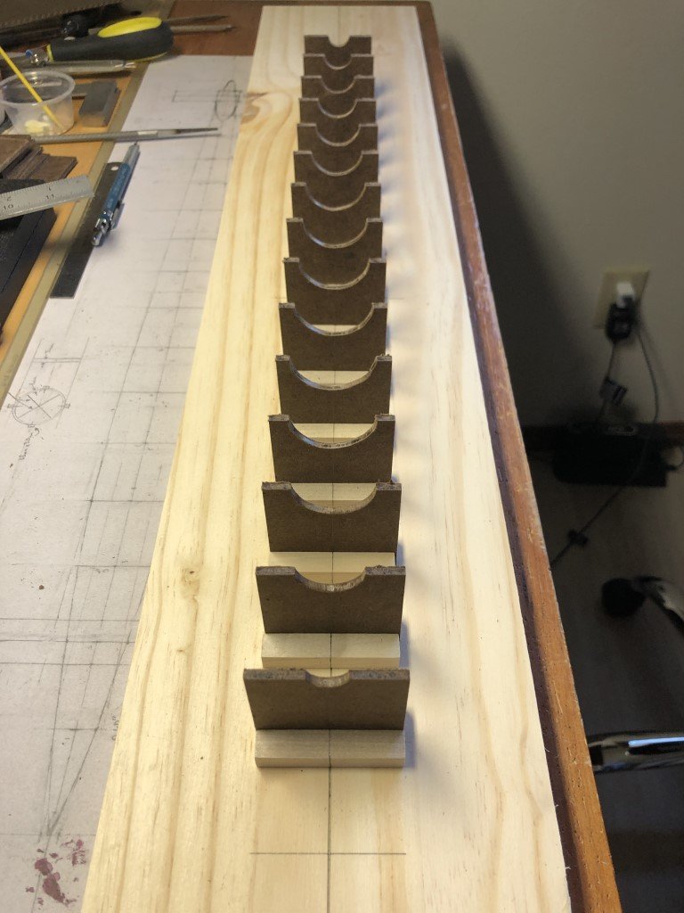
- 288 replies
-
- 5
-

-
- Santos Dumont No. 18
- hydroplane
- (and 1 more)
-
Today I've made a good start on the building jig. I made up supports for hoops 1 - 15; I'll deal with one for hoop 16 after it is remade. The supports are made from 1/8" hardboard and are approximately 2" square. First I had made a number of 2" x 4" pieces with a center line along the 4" dimension. I used the midpoint of this line to mark the center of the pontoons axis. I drew semi-circles to match the outside diameters of the hoops using this mark - Two per blank. They were cut in half and then the semicircles were cut on a scroll saw. A little filing and the hoops fit in nicely. Finally the height of the supports were cut to 1 15/16" (measured from the bottom) so that the side stringers can rest on the supports when they are being attached. I need to mill a notch in the bottom of each semi-circle so that the top / bottom stringer will be accommodated for as the pontoon sits in the jig. I will also add a few tabs to insure the hoops stand perpendicular to the building board.
- 288 replies
-
- 7
-
-
- Santos Dumont No. 18
- hydroplane
- (and 1 more)
-
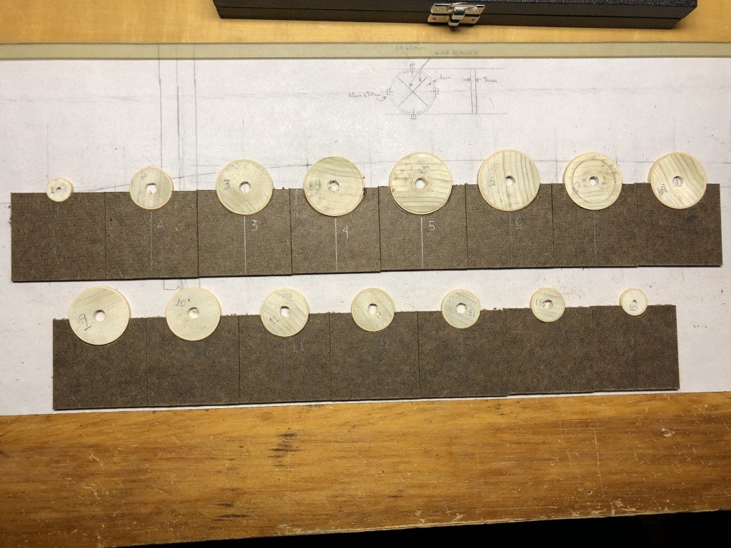
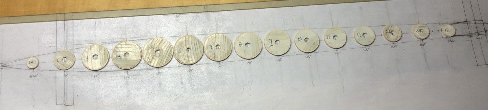
Finally got up the courage to part off all of the pontoon hoops. 15 out of 16 were successful. Hoop 16, the one with the smallest diameter, was a fail. It turned out that I had not been able to lay up the hoop material tight enough to form the solid hoop. I will need to remake that one using a different technique. I may try thin shavings as Craig suggested earlier. I drilled 1/4" holes in the center blanks for hoops 2 - 14. Numbers 1 and 15 have 1/8" holes, but I think I may be able to open them to 1/4" as well. Now that I have these hoops made, I can use their outside diameters to begin construction of the pontoon building jig.
- 288 replies
-
- 6
-
-
- Santos Dumont No. 18
- hydroplane
- (and 1 more)
-
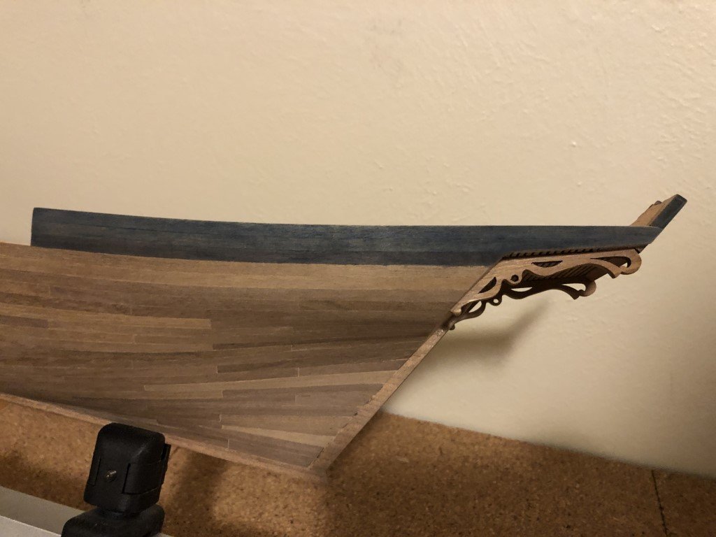
Did some exterior painting today. This was a bit of an experiment for me as the deep blue was done with a watercolor paint.
-
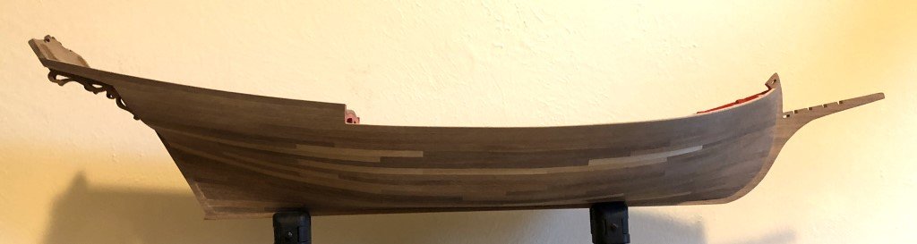
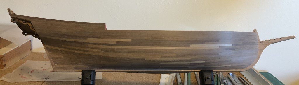
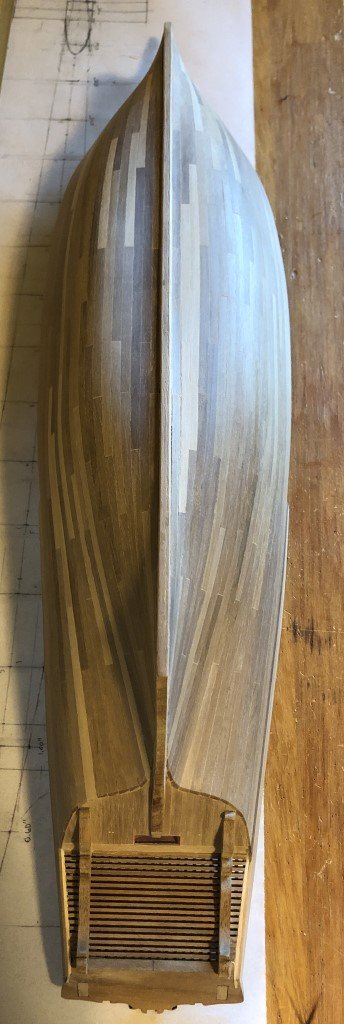
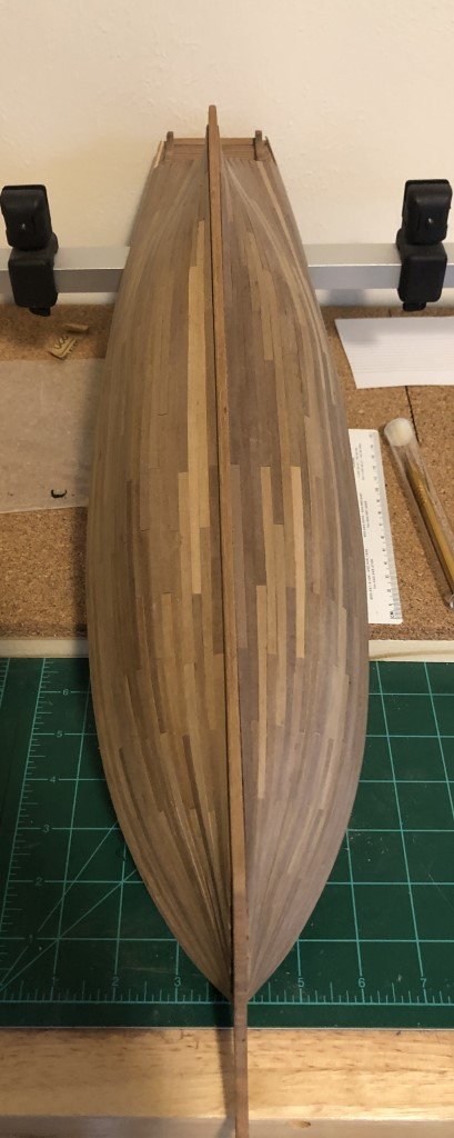
I am now done smoothing the hull. In the previous post, I had smoothed the hull as best possible with paper as fine as 180 grit. I've now gone over the planking with 220 grit sandpaper - this is the finest that I will be using. Here's the starboard side again; not sure if there is any visual difference, but it is now glassy smooth to the touch. One final picture at this stage of the planking from the bottom / aft looking forward. I believe the next step will be some painting. I no longer like the current interior red I had chosen. Now I'd like it to be a deeper darker shade. I also need to make some decisions on the amount of coloring that will be used on the exterior. I think that there will be some exterior paint, but not anywhere near the amount shown on the model as presented in the kit. In my mind the planking looks too nice to cover up with paint.
-
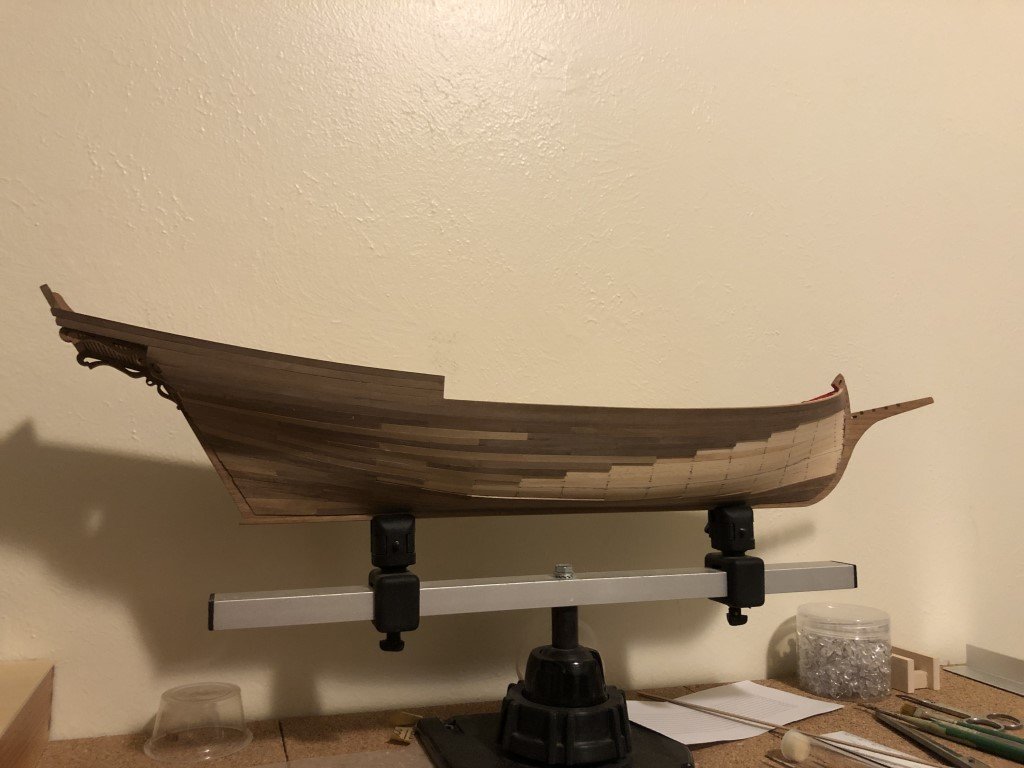
Completed the starboard planking this evening. Everything worked out well - same number of planks on each side! Hopefully there will be some nice weather coming this week so that I can sit outside and sand the planking smooth. I prefer to do the major sanding out of the house and with the wind at my back! I don't think it will take very long as I was able to lay the 1mm x 4mm x 80mm planks quite tight to the hull. I would have preferred for the material to be a little more uniform in color; however, the variation is much less noticeable to my eye than it is in the photographs.
-
I appreciate your evaluation and I hope that my final result does not pale too much in comparison to your 'Eagle of Algier'. I've looked through your log quite a few times for inspiration!
-
Made some good progress - there has been a spring snow storm here, so more modeling time than usual!
-
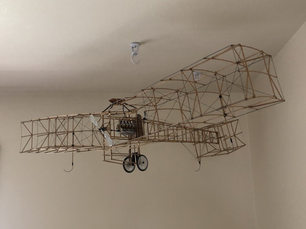
Earlier today I was able to hang my latest finished model - the Santos-Dumont 14 Bis airplane in my office / workroom. So I got some space back to do other tasks, and started the second planking of the starboard for the Sciabecco model.
-
One last picture - I've hung the Santos-Dumont 14Bis in the corner of my office / workroom. As it attempts to fly out the corner of the room, the model should be safe here and easy to view.
- 162 replies
-
- 17
-
-

-
Thank you very much for the compliments and all the posts that you made thru the building, they really helped me think about how the project would unfold. For a machine with such a short 'life', it sure had quite a few configurations. I think that what came out of the build was the middle of the variants - the shortened propeller mount, but not the ailerons. It's certainly not a perfect piece of work and I hope others will see my modeling shortcomings and perhaps get closer to the 'perfect' miniature. Actually, it might make a really good scratch build project, short of the engine most of the build could be accomplished without a great deal of trouble just having the plans. On the other hand, I saw Model Expo selling the model for $99 recently which is not bad for anyone to give it a try!
-
Ron - Thanks, and I hope you consider creating a build log as well. Greg
-
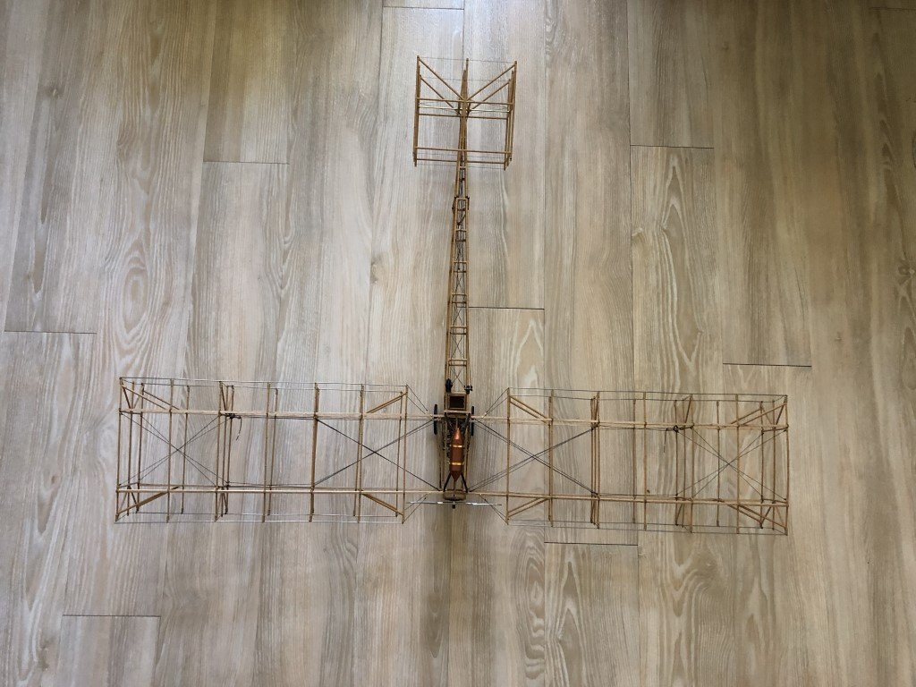
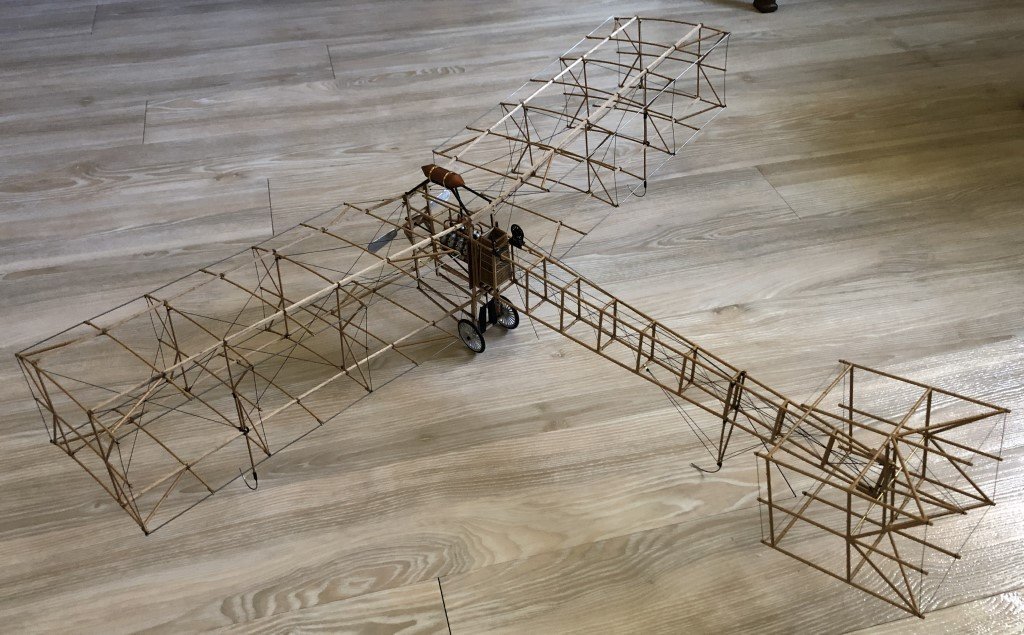
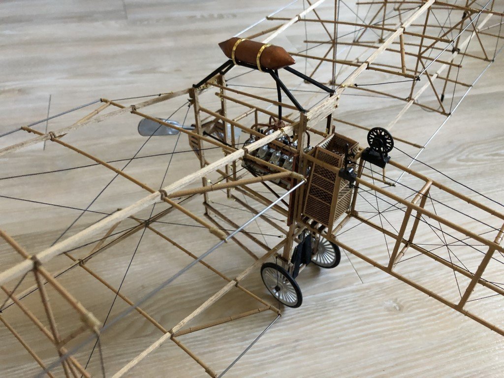
The model is now completed! Overhead view: Three-quarter view: Another shot of the engine / cockpit region: I want to thank everyone that has been following the progress on this model for all of your support. All the best, Greg
- 162 replies
-
- 20
-
-
-

-
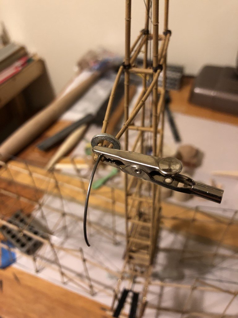
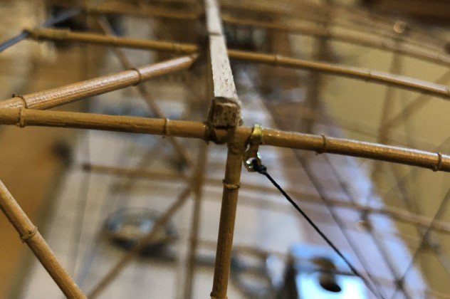
Today's main task was getting the tail support in place. I got the bamboo supports glued and tied in place. Took a little thinking on how I might clamp the lower ends together in preparation for the skid. Finally placed a washer over the two pieces to hold them in place. They were spot glued with CA. After it was dry, I cut a half round into the joint for the skid to sit in. The kit supplies brass wire for the skid. I think the brass wire is not stiff enough to hold the plane up nicely over time. So I have substituted piano wire for the piece. It is spot glued as of this picture. Next it will be wrapped, along with the lower portion of the bamboo, with thread. Once that is done, A small amount of rigging will be added to support the entire assembly.
-
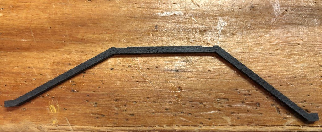
George - While plywood doesn't have as much grain problems as if they made them from basswood, they are still more fragile than I like. If the mounts break again, consider remaking them from some styrene. One of the problems I faced installing the mounts at first was that I failed to angle them in enough. But after playing with the brass straps, I think that getting the straps on first is the way to go. Did you notice that the kit supplied mounts have notches for the brass straps - but they seem to have been made on the top of the mounts instead of the bottom (where I think they should have been)? I've got the display down to two possible locations in my workroom - either on the wall behind my computer desk or hanging in one of the corners of the room. My wife says there is a corner of the family room that it could go in if I want! As soon as the wings were attached, the model got BIG. I am also having some issues with the final assembly because of that. If I happen to get done before you, feel free to continue to post questions. I'll be checking periodically. Otherwise, you can just message me via MSW. Greg
-
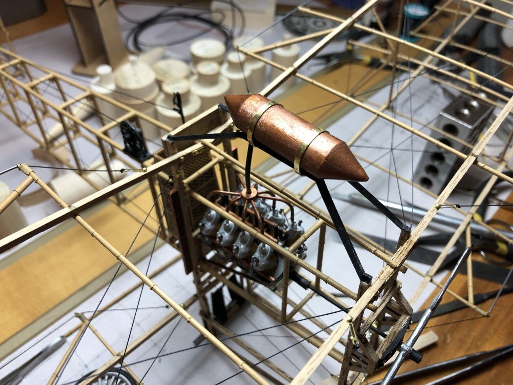
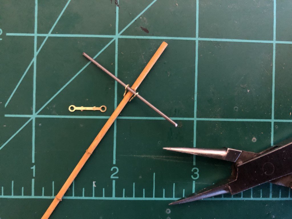
I've just added the fuel tank and fuel line to the engine. Getting the tank in place was harder than expected. At first I attached the mounts to the plane and then attempted to add the tank - this was a fail. I took the mounts off, wrapped the tank and mounts with the brass straps and then put the whole structure in place - this eventually worked out for me. The fuel line was then added to finish this portion of the build. I think it would have been just as easy (and more realistic) to have formed the tank supports from wire and/or had them supplied as castings. I've also added the radiators, the propeller, and the upper wing middle rib. I believe that all that is left now is the landing gear - the wheels, the tail skid, and the wing skids.
- 162 replies
-
- 10
-
-
Yesterday I added numerous pieces of photo-etched brass to the wings. These pieces form anchor points for the bracing lines. Unfortunately, these pieces are not noted in the instruction booklet (they should have been noted on p32 within the 'Metal Parts List') nor are they drawn in the master plan. If you look carefully at the photos on Model Expo you will be able to find a few of them! There are 12 on each wing. They get bent over the wing panels as close to the inside of spars that can be achieved. At first I had some issue with bending them so the two holes would align. I solved the problem by making a starting bend of the piece, putting them over the appropriate rib, pushing a short piece of music wire through the holes to align them, and then pulling the ends together with pliers. Today I spent time getting a good start on the wing bracing. I was able to do all the bracing on the left wing. If I keep focused on this project, it should be done soon. The remaining to-do list is just a handful of (hopefully straightforward tasks): Right wing bracing Wing landing skids and bracing Tail support skid and bracing Attach wheels Fuel tank and fuel line Radiators Propeller I've made a final decision to not include ailerons on my model.
- 162 replies
-
- 10
-
-
-
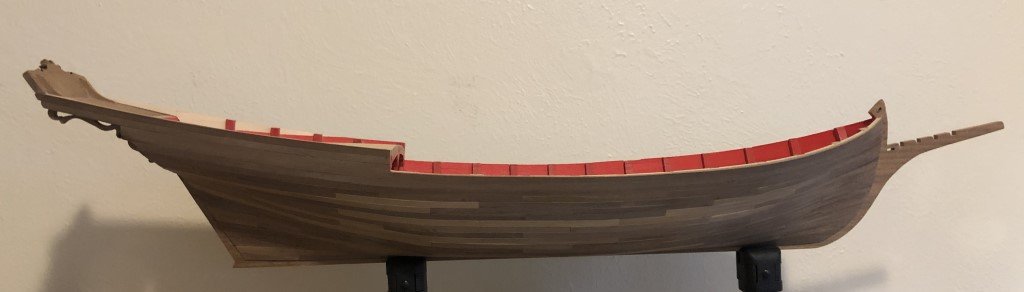
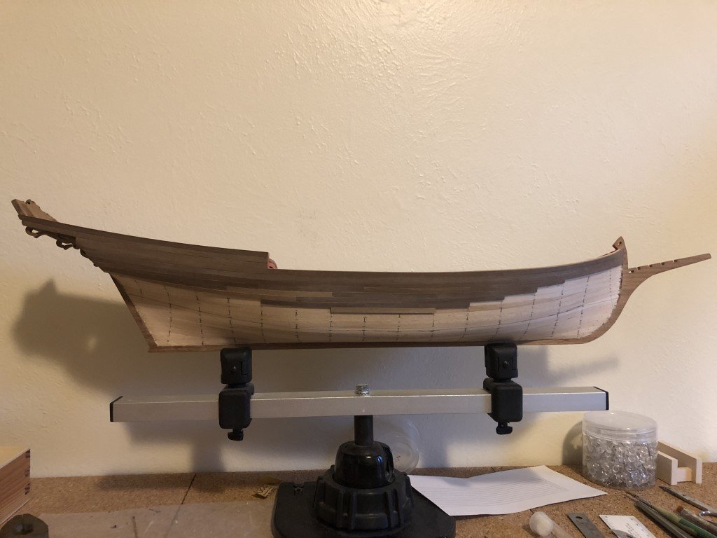
I've finished the 2nd planking of the port side. I was hoping not to need any stealers, but it turned out that one was required. If the kit had come with wider material for the garboard (or I had matching wood available), then I could have done the planking stealer free. Either way it's looking good to me.
-
The first belt on the port side is done. It should look nice once it is smoothed and a finish is applied. Time to mark out the lower belt and continue on.
-
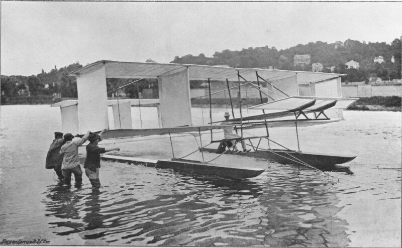
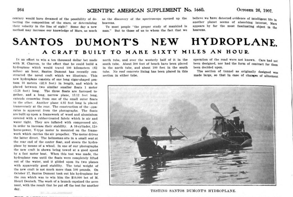
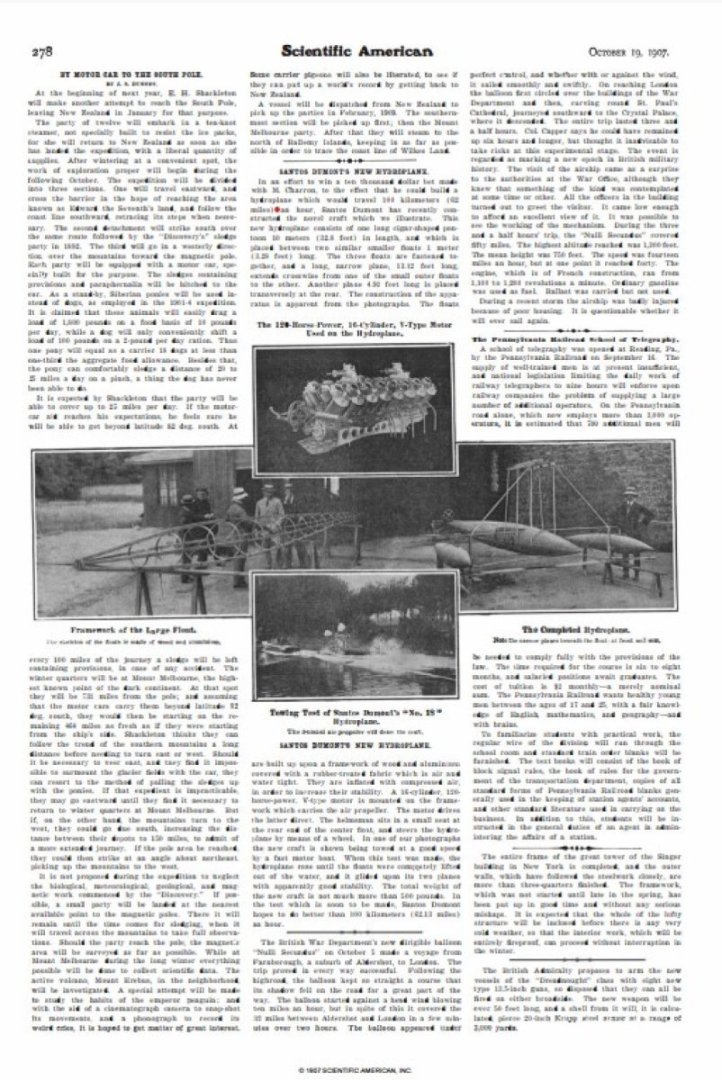
Thank you for providing this link. I am grateful for your interest in the craft and willingness to share. However, I am not sure of the information presented in the document - I really wish that there had been references included. My comments below are not meant to discredit, but to critically question the translation (I don't read French either!) in light of other information that I have gathered. I have not run across other information noting any collaboration with Voison, I believe that they were actually competitors. As translations can sometimes go astray, I wonder if some comparison was being made to Voison's 1905 glider that was (like the No 18 during testing) pulled by a racing motor boat on the Seine. I am still looking for additional sources that would validate 'three floats built by Lachambre'. My impression, from the sources that I have read, imply that work on his crafts were done by a group of builders / mechanics that were long-term hires by Santos-Dumont. There are not many contemporary written in English about the No18, but here are a couple printed in Scientific American from October 1907. In neither case is the No 18 portrayed as a plane; it is clearly portrayed as a boat. The 'driver' is described as helmsman - a term typically used for the person controlling a ship or boat. The hydrofoils are referred to as wings - perhaps that is what wings in the translation refer to. I certainly will not forget what you have shared and should I find evidence in support of the translation I will immediately pass it on. Thanks again, Greg
- 288 replies
-
- 4
-
-
- Santos Dumont No. 18
- hydroplane
- (and 1 more)
-
Do you think that this is true to the prototype or a more modern control solution? Before watching this video, I had conjectured that the original ailerons were connected to two cables opposed to one cable and a spring.
-
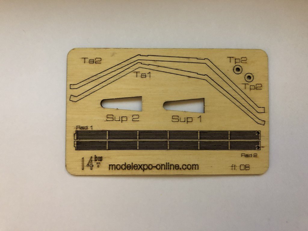
George - The tank supports and the radiators are laser cut on the same sheet of wood that the canard support attachments to the fuselage were - since you have the supports Sup1 and Sup 2 on your model, I'm sure you have the other parts. For me, the laser cutting of the radiators is a highpoint of the kit - I'm just hoping I can release them from the sheet without damage.
-
I have not seen a picture and / or diagram depicting the aileron control system. Like you, all that I have found is the verbal description of lines being connected to his coat and body movement would then translate into aileron movement. If I do locate additional information I will share!