
HOLIDAY DONATION DRIVE - SUPPORT MSW - DO YOUR PART TO KEEP THIS GREAT FORUM GOING! (Only 51 donations so far out of 49,000 members - C'mon guys!)
×


Greg Davis
-
Posts
805 -
Joined
-
Last visited
Content Type
Profiles
Forums
Gallery
Events
Everything posted by Greg Davis
-
 Today I prepared a set of forms for the hoops. I made these starting with poplar dowels with 1.5" and 1.125" diameter that I picked up at the local Menards. Now it is time to make a lot of paper-thin wood to wrap around the forms.
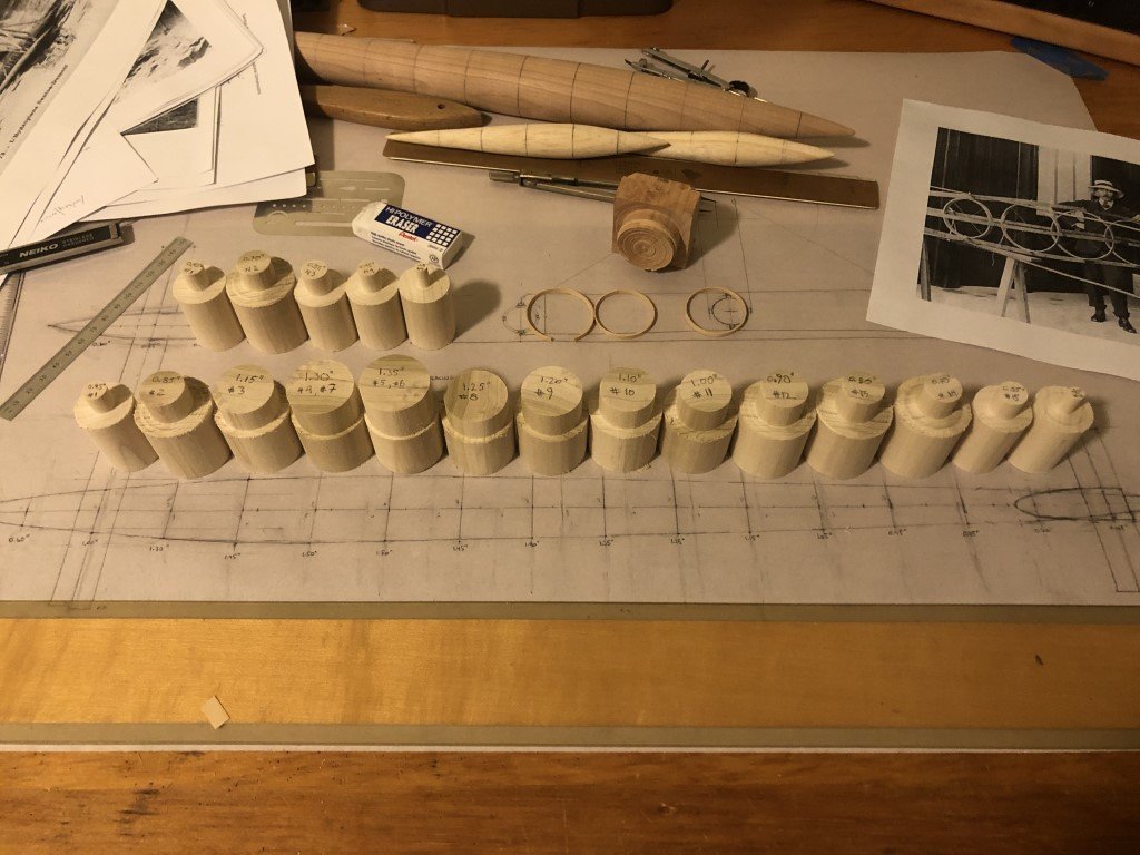
- 288 replies
-
- 7
-

-
- Santos Dumont No. 18
- hydroplane
- (and 1 more)
-
that would match well with the illustration
-
Today I got notified that Model Expo has sent the replacement engine cylinder! I think I got their attention this weekend by asking for a store credit as I had nearly given up on ever seeing the replacement part.
-
George Thanks for sending the pics - looks really nice! Greg
-
George - I did it as a butt joint as well - I added a fillet of CA between the three parts to reinforce the joint. Good question about the Cn2! I don't know, I just attached the nose to the Lt4 brass tubing (again with a butt joint). After the rigging lines were put in place I felt pretty good about the nose structure. I'm not familiar with the Diamond Glaze product - I hope you like the result you have gotten! Greg
-
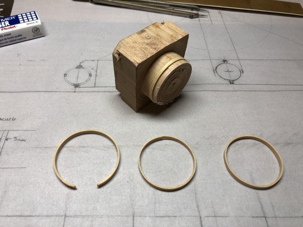
Two more tries and I think I have a method that will work. I was able to sand some C-boxwood down to 0.35mm with my Byrnes thickness sander. I then trimmed some strips off to use for the lamination. For the second try the wood was laid in a spiral - easiest to do, but I felt the inner bump was to extreme. I don't think I can reliably create a long bevel to get a smooth inner circle. So the third try is a three layer lamination were the seam from each layer is offset. I believe the result is worth the extra effort, especially considering there are less than 30 hoops to make - not much in comparison to framing a ship! In this picture the hoop trials go from left to right: the broken two layer laminated 1st try, the inner bumped (at the top) 2nd try, and the three layer laminated 3rd try. The mold I used for the trials is above the hoops. I don't need to make a separate mold for each hoop as in some cases there are multiple hoops of the same diameter.
- 288 replies
-
- 10
-
-
- Santos Dumont No. 18
- hydroplane
- (and 1 more)
-
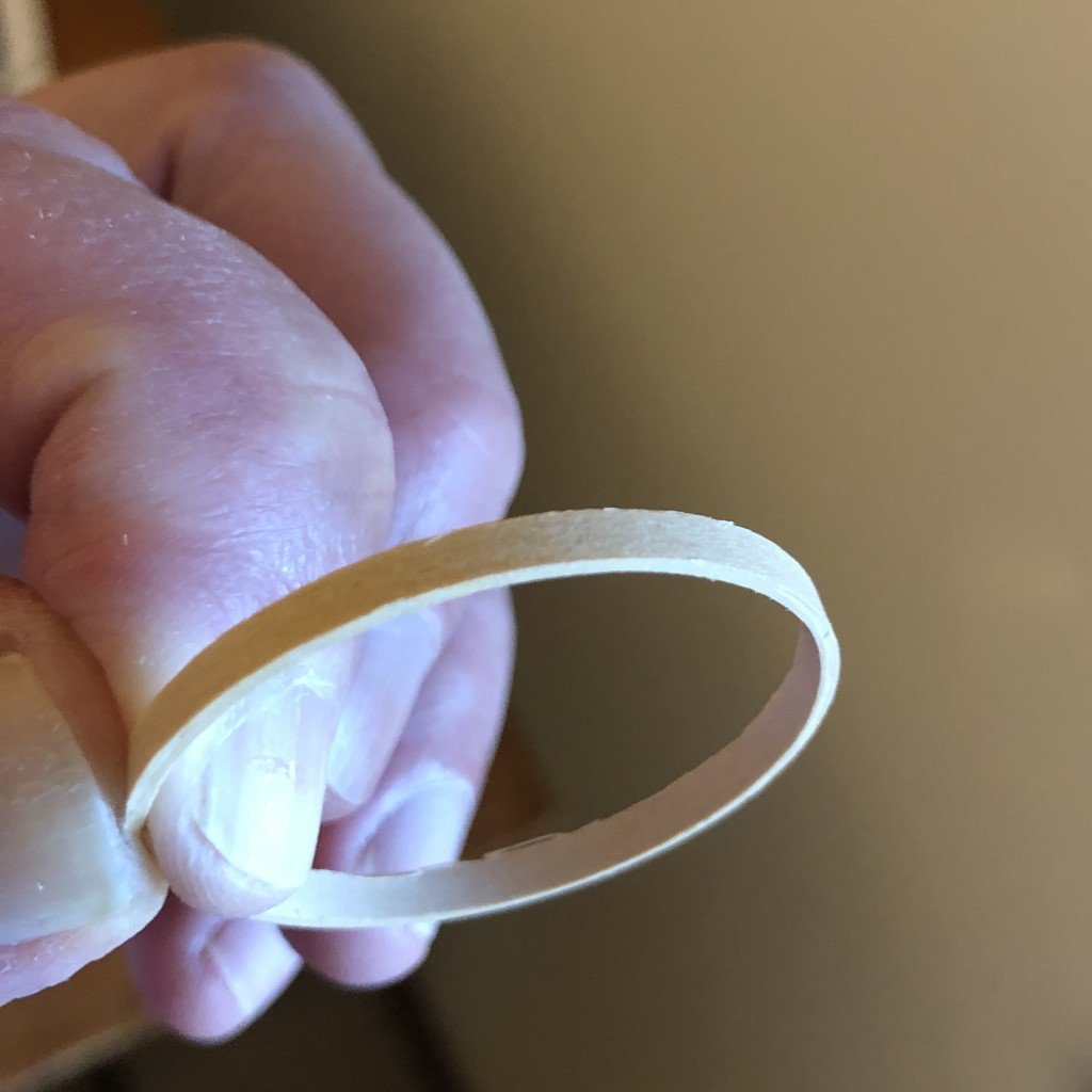
The hoops are going to be 1mm thick and 3mm wide. I made a mold for what would be the largest diameter hoop 1.25in. Unfortunately, this first hoop experiment was not successful - it broke taking it off the mold. Other than that it looks nice! I had made this hoop using two approximately 0.5mm thick pieces of boxwood, but after bringing the thickness of the hoop back to 1mm it was to thin near one of the layer joints and fell apart there. I was worried that this might happen. Now I am sure that there should be at least three layers in the laminations to guard against this type of separation. This will require me to make up some material that is around 0.35mm thick. This will be a new challenge for me. In the past I was successful making sheets of 0.5mm cherry, so I'm hoping I can go a bit thinner with the Castello boxwood.
- 288 replies
-
- 8
-
-
- Santos Dumont No. 18
- hydroplane
- (and 1 more)
-
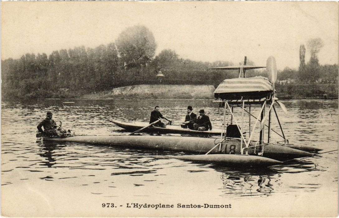
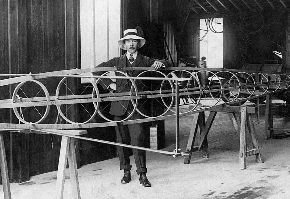
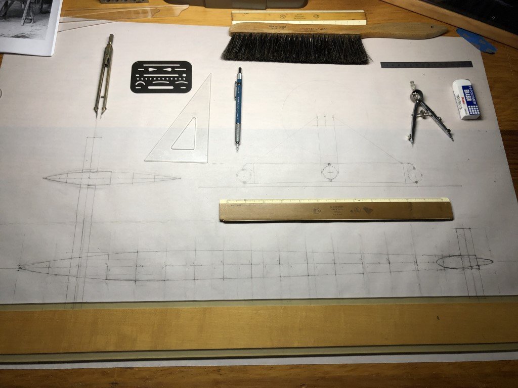
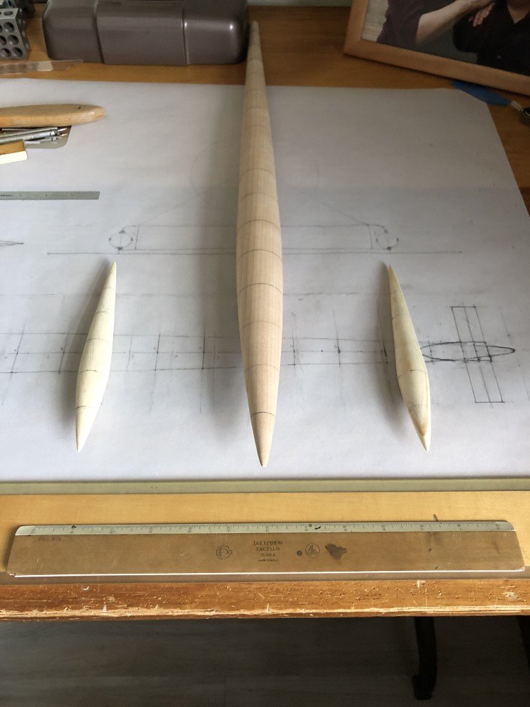
Toward the end on last year, I became acquainted with a boat that Alberto Santos-Dumont built in 1907. The boat - the No 18 hydroplane, was Santos-Dumont's only watercraft; the rest of his many notable creations were aeronautical in nature. He built and flew many balloons and dirigibles, but may be best known for the 14bis - credited to be the first plane to take off under its own power and flown publicly in Paris. For many years, in Europe and in Brazil (his home country) Santos-Dumont was credited as the first to fly an airplane. Santos-Dumont was independently wealthy and thus had the means to pursue his desire to build and fly heavier than air crafts. Most of his creations where constructed in France where his main residence was located for many years. He also liked a challenge, often associated with a bet. The No 18 hydroplane came about due to a bet that asked for the first boat to achieve 100km/hr along a course on the Seine (averaged over two directions). No plans for the No18 are know to exist; in fact Santos-Dumont destroyed many plans and notes in 1918 after being accused of spying for the Germans. It is most likely that the plans and associated building notes for the No18 were destroyed at that time. Over in the 'Discussions for Ship Plans and Project Research' portion of MSW I have posted more about the boat and my quest for information. Fortunately, with positive encouragement from MSW members and a number of helpful contacts I have been able to collect enough reliable information that I am confident that a quality model of the No18 hydroplane can be created. This is what I aim to do. Mostly based on published articles and historical photographs, I have been able to draft plans to build a model in the scale 1:16. The model will be just over 24" long, the main hydrofoil gives a width of about 15", and the height will be about 8". The original was 10m long, 6m wide and had a propeller with a 2.1m diameter. Power was provided by an Antoinette V16 engine. The model will show interior detail of the boat's structure. I have chosen Costello boxwood for the wood structures within the model. To get started / validate my drawings in some manner, I decided to create a mockup of the main pontoon and the two outrigger nacelles. The shapes look good to me, so now I will be focusing on making the cross-sectional hoops that hold the shape of these three objects. There are 17 hoops to be make for the main pontoon and 5 for each nacelle. I plan on using a lamination method for the hoops - so making some thin strips of wood and a molds for the hoops will be the first tasks. While I'm working on the hoops, I will be thinking about how to make a jig that will keep them in place as the longitudinal stringers are attached to each.
- 288 replies
-
- 12
-
-

-
- Santos Dumont No. 18
- hydroplane
- (and 1 more)
-
George - Sounds like you are making great progress - post a pic or two! I had the same issue with the basket; it was a really tight fit, so I put the crosspieces in after the basket was inside the fuselage. The instructions are challenging / ambiguous at times. I'm pretty sure that I will be replacing many of the ribs that are between the wing panels because I don't like how the bamboo didn't keep the airfoil shape. I'm going to use basswood for the replacements. I took some 1/16" square basswood and passed it thru a drawplate to round off the edges. After painting and putting the nodes on they should match the rest of the material. Good luck with the canard. My parts requests have been 'processing' for since the end of November for the cockpit parts and mid-December for the cylinder. I hope that you get your parts quickly and don't need to experience such a delay. Greg
-
End of January update: Same as end of December update, still waiting on Model Expo for replacement parts.
-
Keith Thank you for the links - the micromaster boats are amazing, but there is no way I'm spending > $250 on boats to give away! They must have a pretty nice 3-D printer. I've recently thought about getting a 3-D printer for making some parts myself. I haven't been able to determine what a minimal outlay for reasonable results would be. There are so many printers on the market. I've already been thru the Cornwall site a few times and didn't see what I wanted. I've ordered from them previously and, like you, have had good experiences. Thanks again, Greg
- 123 replies
-
- 1
-
-
- Le Pourquoi-Pas
- Constructo
- (and 1 more)
-
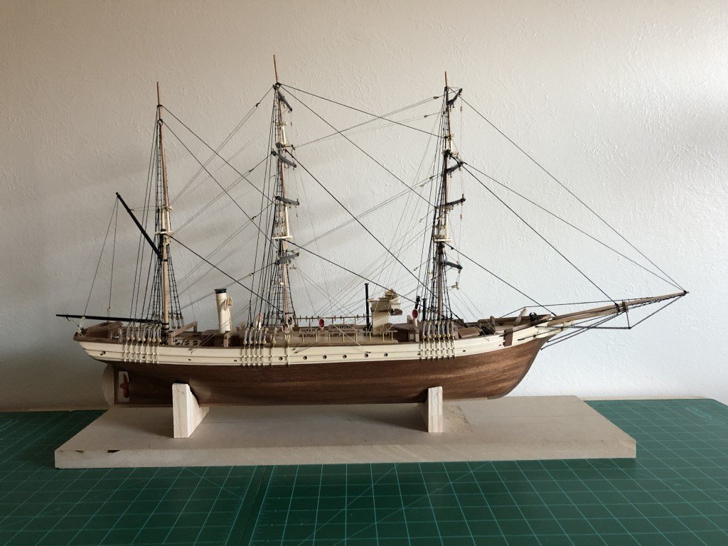
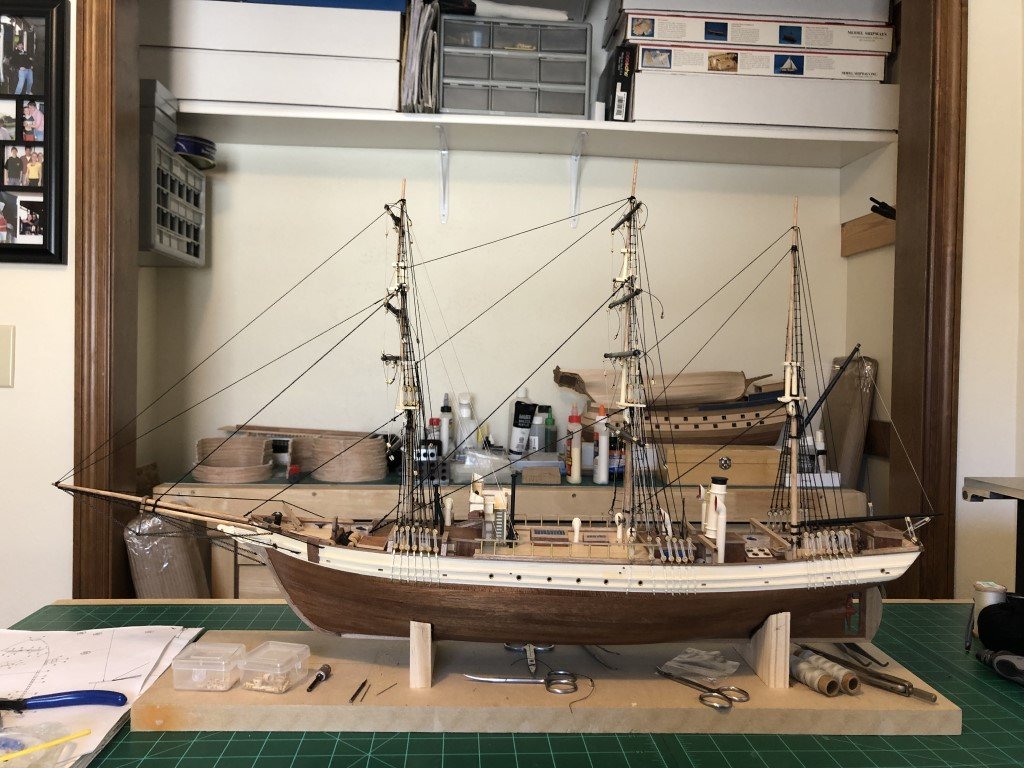
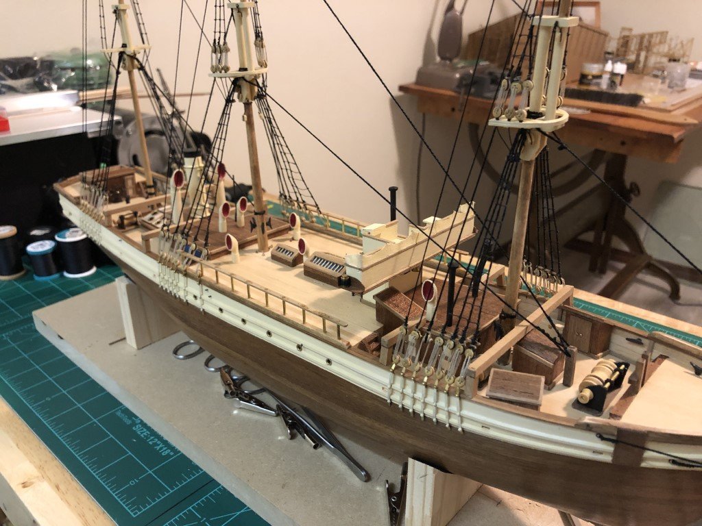
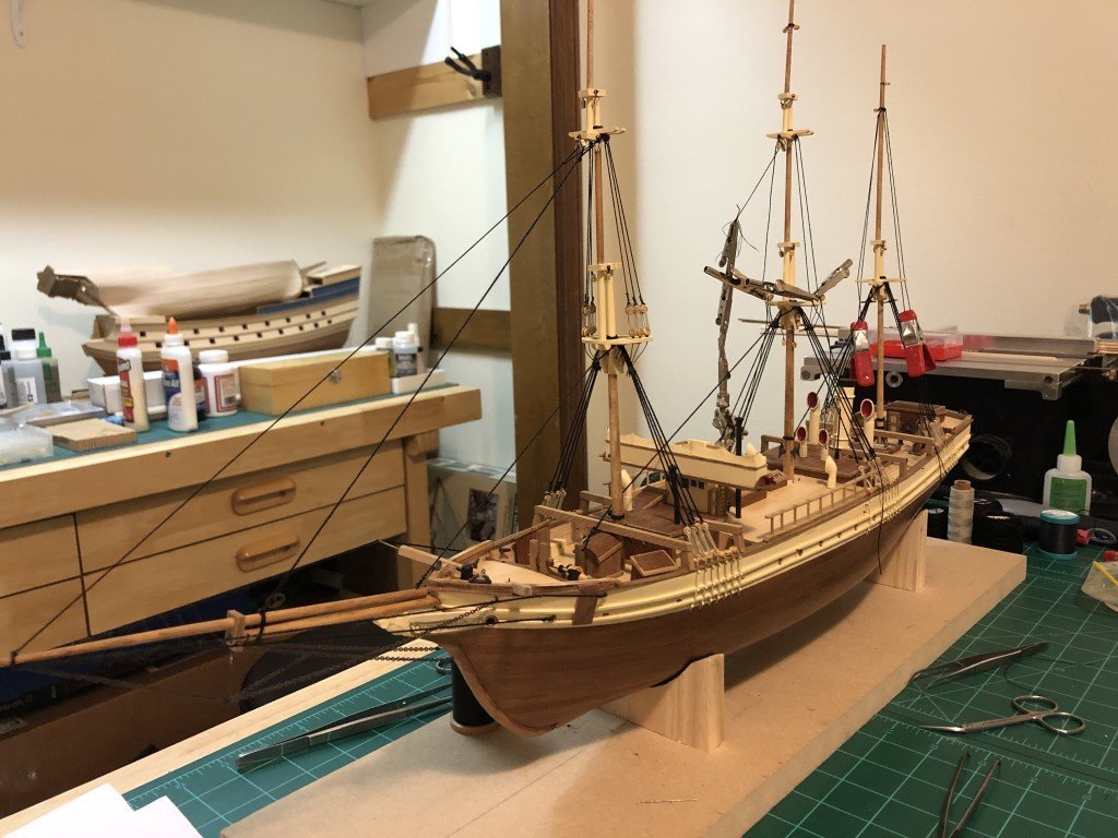
Braces have been taken care of. No more rigging planned at this point. I'll be setting the main assembly aside for a while; hopefully in a safe place! I'm looking to have the project complete for when it warms up and the snow / ice goes away - probably well into April. Likely on and off work till then. Time to work out what the case will be made of. Currently thinking of using Cherry so the case can be darker in nature and complement the hull. Once the case of the base is done, I'll make the two cradle type mounts - these will be painted black and attached to the case base. Once the ship is mounted, I plan to add the anchors, either hanging or laying on the case base. Additionally, I want the ship to have all 6 boats. The kit came with two cast boats that are the correct size for the upper deck. There should be two slightly shorter boats alongside the smoke stack and then two additional (even shorter) boats ahead of the foremast. I have searched the web countless times looking for boats that fit the need of this ship but have not been able to find anything that will work. Looks like I will need to fabricate them myself.
- 123 replies
-
- 6
-
-
- Le Pourquoi-Pas
- Constructo
- (and 1 more)
-
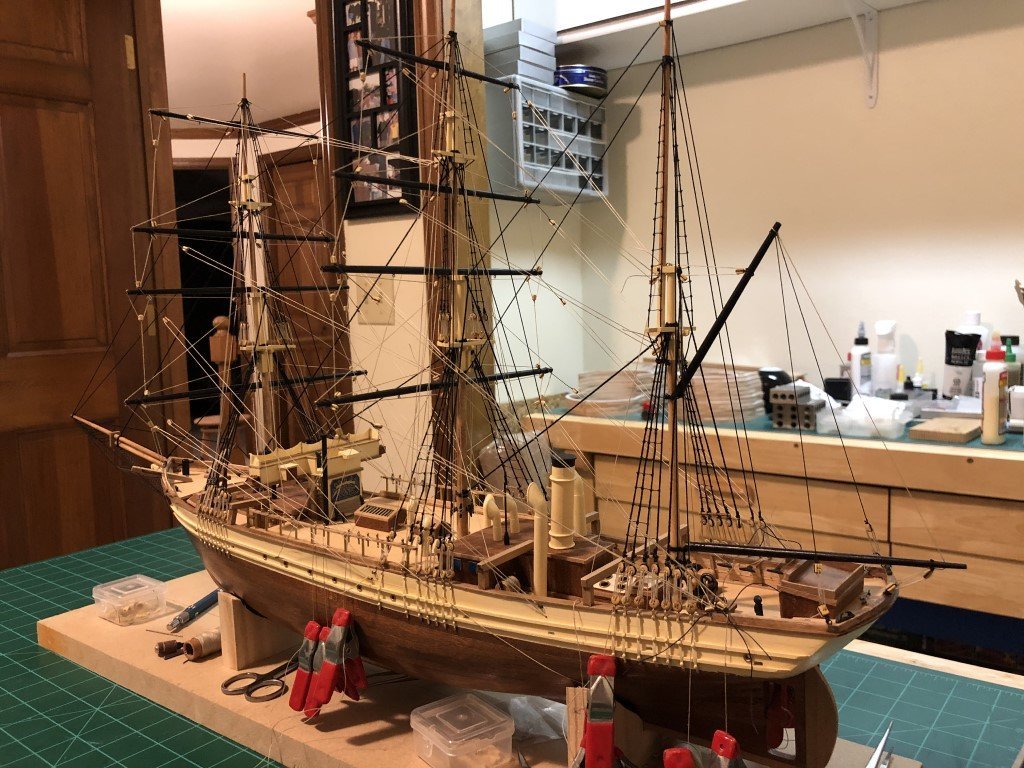
I set up the braces this evening. Tomorrow when I have natural light I will take another check that the lines are where they are suppose to be. Then I can complete the attachments to belaying pins and cleats.
- 123 replies
-
- 3
-
-
- Le Pourquoi-Pas
- Constructo
- (and 1 more)
-
Foresail and mainsail rigging done - I always like the three blocks that come together for this part. Time to start with the braces.
- 123 replies
-
- 2
-
-
- Le Pourquoi-Pas
- Constructo
- (and 1 more)
-
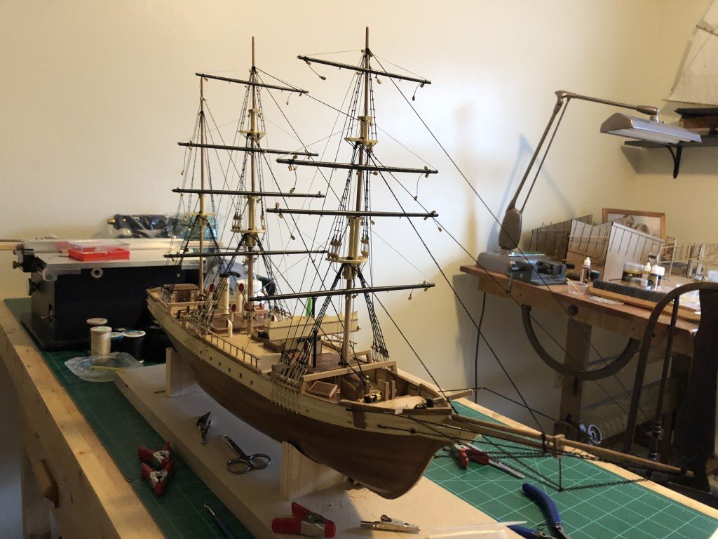
The last two spars are in with their respective rigging. Now I can see just how much room this model will take up. Looks like it is turning into an acceptable display model! The list of tasks to complete is shrinking: lower mast sail handling rigging braces anchors ship boats finishing touches display mounts display case The launch date is coming into view!
- 123 replies
-
- 4
-
-
- Le Pourquoi-Pas
- Constructo
- (and 1 more)
-
George I agree with you on the wing jig labeling - it appears that left and right has been given from the perspective of looking at the plane from the front and not as if you were in the pilot basket. Still waiting on the cylinder - hopefully by the end of the month! Its giving me time to finish another model that needs to be wrapped up. I haven't made any attempt to work on the fuel supply system yet. I have looked at the instructions a number of times and I was thinking that the main diagram labels are not correct. I think that along the longest diagonals you need to have HGI and IGH as opposed to HGH and IGI to keep the diagonals the same length. Greg
-
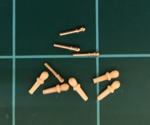
Since yesterday, I was able to add most of the sail handling rigging - the last bit, associated with the lower masts will be added later. A few of these lines are attached to pin rails. When I got to this part I decided to rummage thru odds and ends for enough metal pins to replace the wooden ones provided (that were badly out of scale and historical period for the ship). Now I have started fashioning the two spars that attach to the mizzen mast.
- 123 replies
-
- 3
-
-
- Le Pourquoi-Pas
- Constructo
- (and 1 more)
-
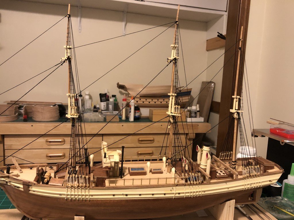
Spars and lifts for the fore and main masts are in place: Certainly will be adding the spar braces. In the meantime, thinking about how many of the sail handling lines are going to be added.
- 123 replies
-
- 4
-
-
- Le Pourquoi-Pas
- Constructo
- (and 1 more)
-
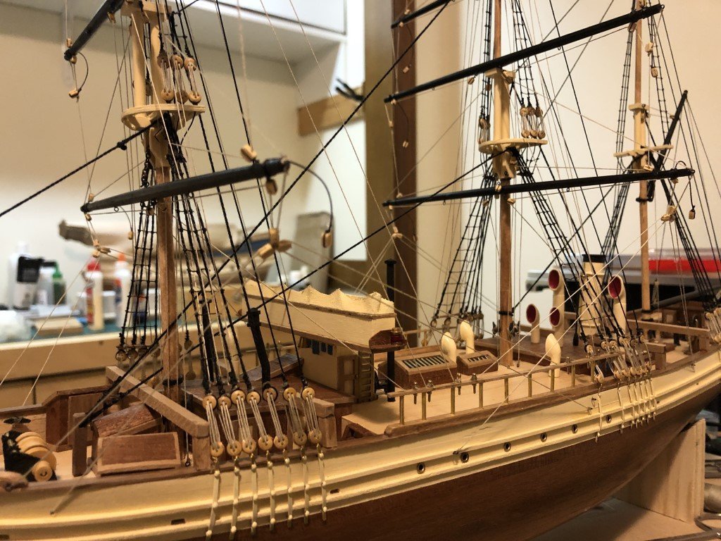
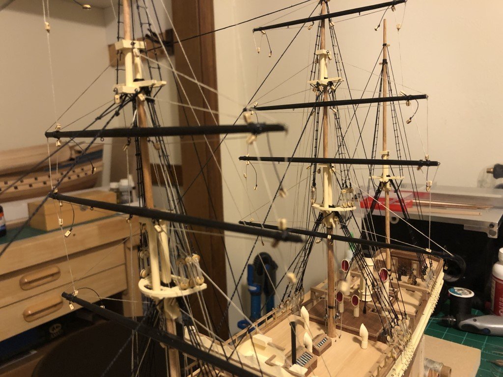
Now the starboard side ratting is also done Next up: some spars!
- 123 replies
-
- 6
-
-
- Le Pourquoi-Pas
- Constructo
- (and 1 more)
-
I started with the rat lines on the port side. I expect this side of the ship will end up against a wall when displayed, so it was a good place to reacquaint myself with clove hitches! Time to swing around to the other side and tie a few more knots.
- 123 replies
-
- 4
-
-
- Le Pourquoi-Pas
- Constructo
- (and 1 more)
-
All of the back stays are in place. Just the rat lines and the standing rigging will be done.
- 123 replies
-
- 6
-
-
- Le Pourquoi-Pas
- Constructo
- (and 1 more)
-
End of Year Update The 14 Bis will continue to stall for at least a couple of weeks 🤔. Here's the latest correspondence from Model Expo: Greg, I am here in Brazil and I picked the metal parts from the engine. Will be back Jan 10th and have it shipped. The wood parts are already in the US. You'll have it all shipped as soon as I get back. Best Regards and happy new year!
-
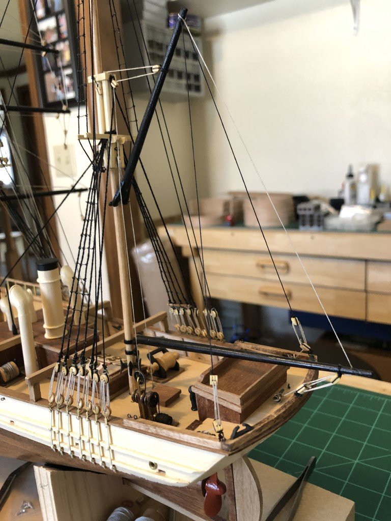
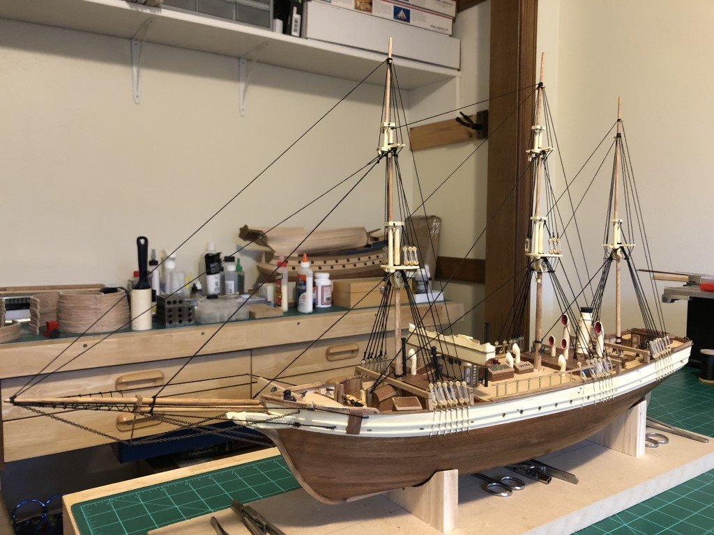
All the shrouds and fore stays are in place. Tomorrow the back stays begin followed by the rat lines!
- 123 replies
-
- 5
-
-
- Le Pourquoi-Pas
- Constructo
- (and 1 more)
-
I did - a good Holiday Season to you and everyone else!
- 123 replies
-
- 2
-
-

-
- Le Pourquoi-Pas
- Constructo
- (and 1 more)
-
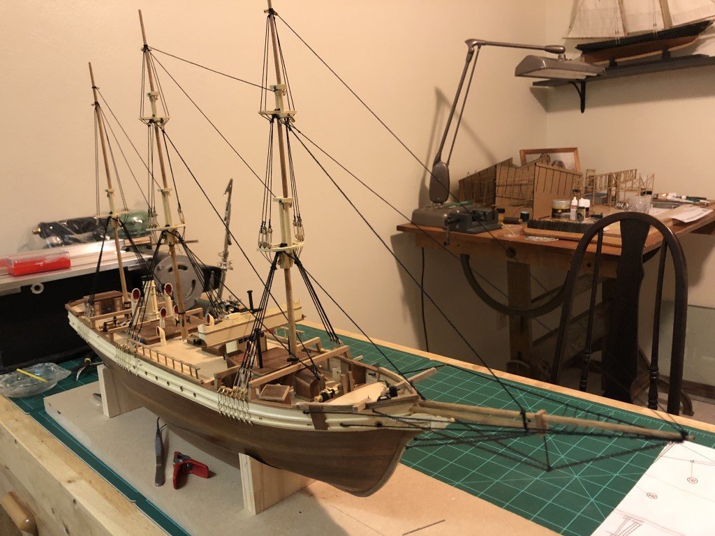
The lower level of standing rigging (including a few stays) was finished yesterday and I'm now on the second level. More shrouds are being added currently.
- 123 replies
-
- 4
-
-
- Le Pourquoi-Pas
- Constructo
- (and 1 more)
