Greg Davis
-
Posts
807 -
Joined
-
Last visited
Content Type
Profiles
Forums
Gallery
Events
Everything posted by Greg Davis
-
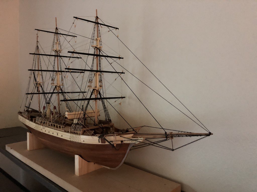
 After months of having this model sitting on a shelf, I finally added the 6 ship's boats and the anchors. The ships boats are not as good as I had envisioned, but will do. I decided to paint them all a color similar to the hull planking and then stowed them upside down. I'm taking some 'artistic liberty' here, as the actual boats were probably white at this time and stowed upright as the ship had a significant davit system for the boats. Here again I choose not to include this detail. I'm going to call it job done as far as the model goes. Time to build a case and get this out of the house!
- 123 replies
-
- 7
-

-

-
- Le Pourquoi-Pas
- Constructo
- (and 1 more)
-
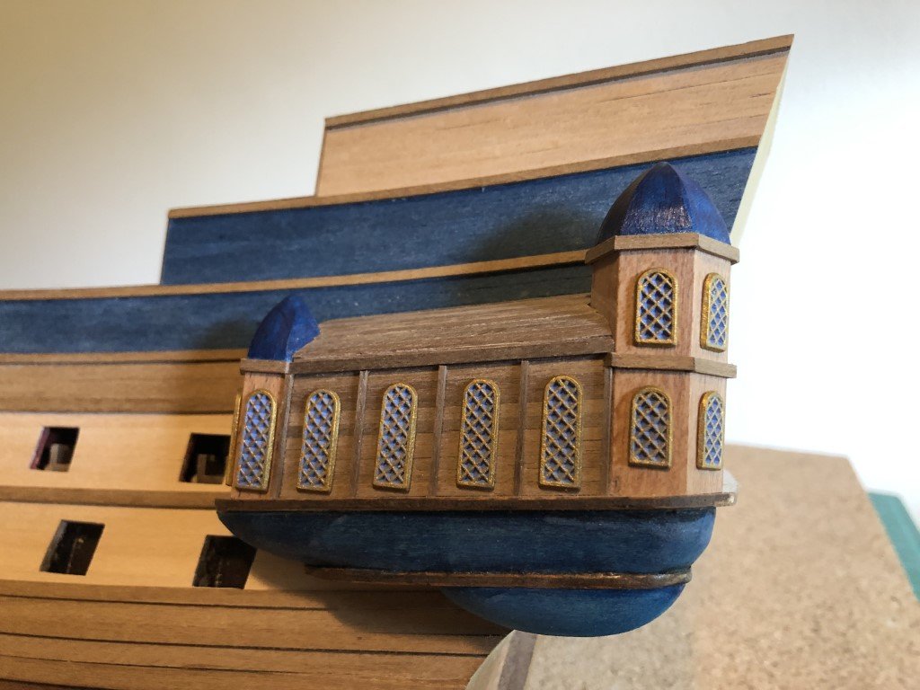
After a bit of touch painting, the windows have been installed:
-
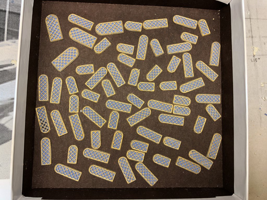
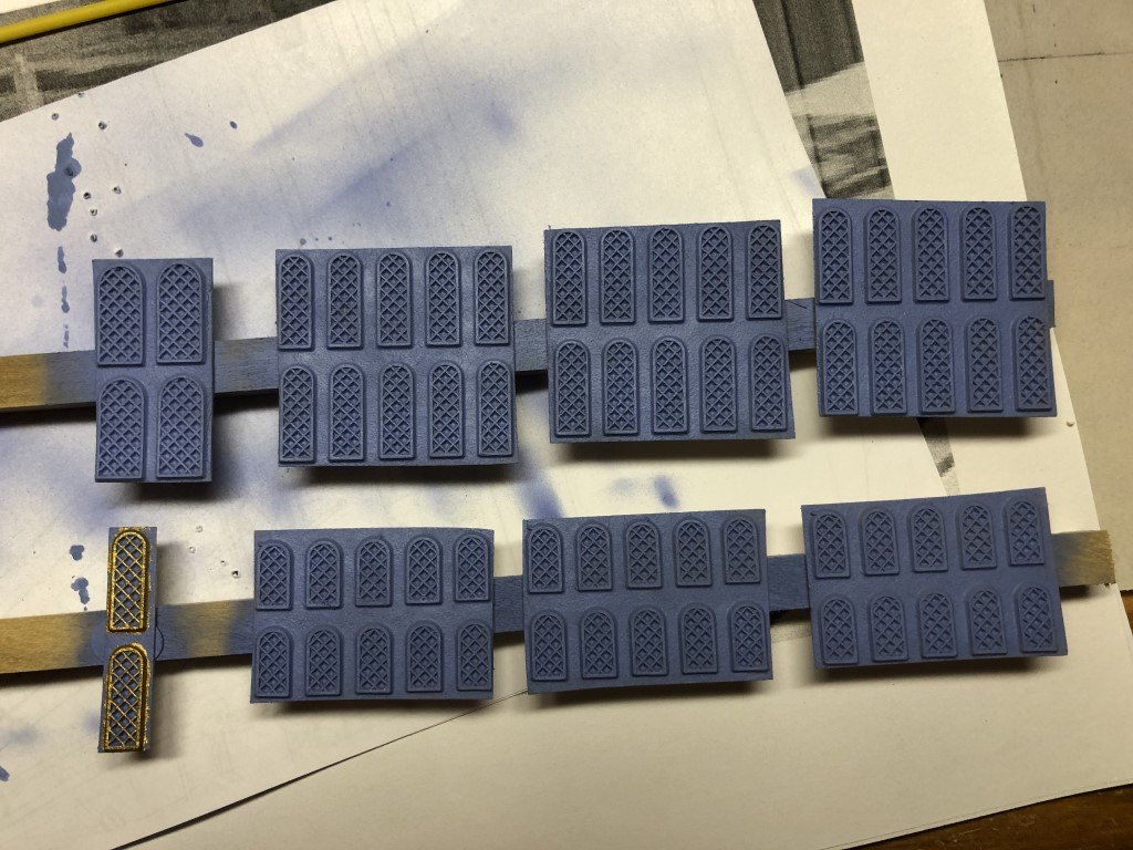
Got them all cut out / cleaned up today. Two or three have a bit of damage, but they will not be needed as there are extras of the tall and short narrow windows. There are no extras of the larger stern windows - fortunately they are all usable. The outer window casing edges need to be repainted and then the windows will be ready to install.
-
Can't quite believe it took 3 days to paint all the window grates - hard on the eyes for me! Now its time to start cutting all of the windows out. This may also be time consuming!
-
Thank you for looking!
-
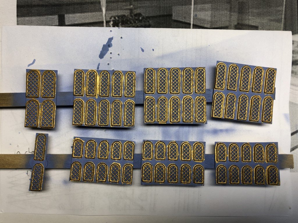
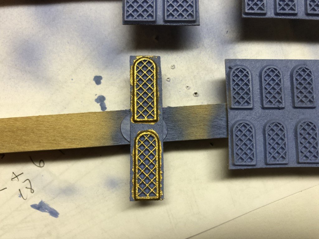
I'm planning to use the pressed fiber windows. Today I airbrushed the windows blue and am starting to paint the gratings and window frames by hand:
-
That is quite an 'interesting' looking machine! I just watched a couple of videos of it on the water - amazing! thanks Greg
- 288 replies
-
- 3
-
-
- Santos Dumont No. 18
- hydroplane
- (and 1 more)
-
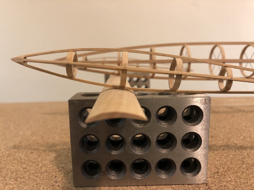
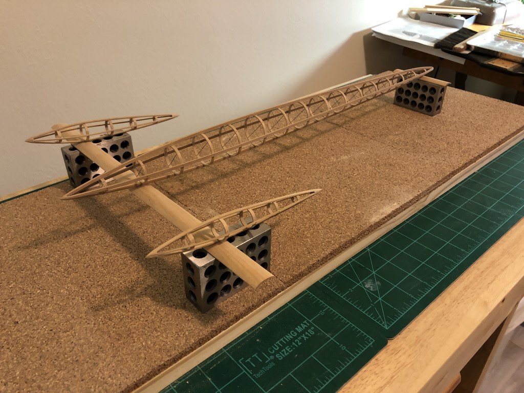
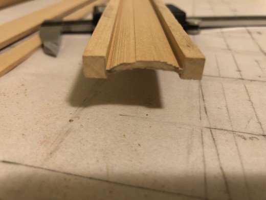
A couple of Dremel flap sanders later and some finish sanding has resulted in some good looking hydrofoils. Here is a mock up with the pontoon and nacelles. Now I really need to do some metal work!
- 288 replies
-
- 9
-
-
- Santos Dumont No. 18
- hydroplane
- (and 1 more)
-
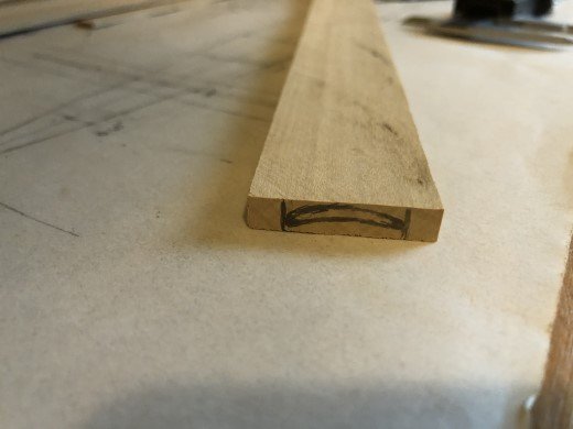
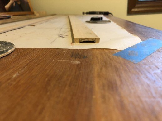
Decided to give a go on the hydrofoils today. I cut a piece of boxwood 1/4" thick, a bit wider than the chord (~ 2cm), and about 2 feet long. The main hydrofoil is about 15" long the rear one about 4". After marking the foil shape on one end of the slat, I repeatedly ran it across my table saw to 'mill' the basic shape. The extra width of the slat allows the slat to sit flat on the table saw for this operation. Now I will sand the final foil shape, except for the leading and trailing edges - they will be shaped after parting the mostly formed hydrofoil from the extra material. I hope this works!
- 288 replies
-
- 7
-
-
- Santos Dumont No. 18
- hydroplane
- (and 1 more)
-
Thank you so much for the offer! I really look forward to what you might be able to fill in the missing gaps from my kit. I do have the window frames (unlike you, there is no way I'm going to do all the work to open up and lighting he cupolas!), stern lanterns, and false cannon barrels. Greg
-
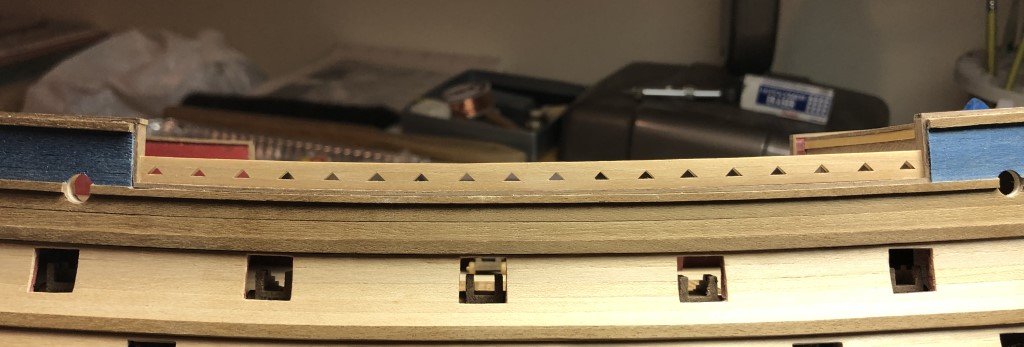
One triangular bulwark in place - one to go as well as the corresponding top rail. Seems to look better than what I could possibly do with the kit supplied pieces.
-
That's wonderful that you will take a look!
-
Got a good start on one of the triangular bulwark structures today. I've tried to build in some of the curvature. Once this is dry some finish sanding will even up all the pieces and will hopefully have a nice look.
-
This is a wonderful offer! The castings I am most looking for are the 14 closed gunports (roughly 1cm wide) as well as the (8 cm) ship's boat. The capstan is also missing, but that I can recreate if necessary. If you do find them, we can arrange shipping etc. Thanks! Greg
-
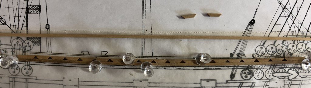
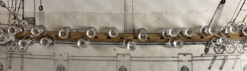
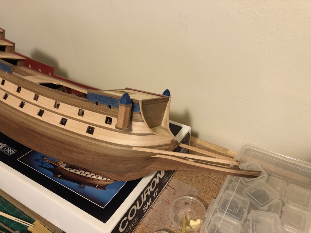
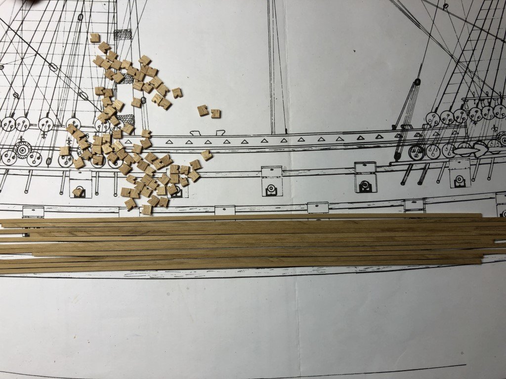
Did a bit more work up front - added some of the head rails. The upper ones are actually L-shaped. The recess is for a good deal of grating. Unfortunately, the appropriate amount of grating was not included in the kit. I didn't feel like making any so I went ahead and ordered enough to finish the project. It should get here in a day or two. Started work on, and attached, the front cupolas. They will get lights at the same time the stern ones do; i.e., not today! Between the blue planking, fore and aft, the bulwarks are to be raised with wood containing a decorative triangular motif. The kit includes numerous bits of wood with notches that when matched properly form the triangular openings. Unfortunately the supplied pieces are not well formed having rough / chipped edges and inconsistent heights. The amount of work that would be needed to get a reasonable outcome from these pieces is definitely not worth the time and effort. I will be making this section of bulwark in a slightly different fashion instead. To get started, I've milled some 2mm x 2mm Castello boxwood. The bulwarks will then be made in three layers - first a 2x2 strip, next a line of trapezoids about a centimeter wide and sides that will form the triangular shape, finally another 2x2 strip will top it off. Once this is all in place another walnut rail is to be added. Unfortunately, soon after ordering the grating material I found that there were other missing parts from the kit - notably a number of castings that I was planning on using. So a request went off to Model Expo (where I had purchased the kit) and they claim to have forwarded the request to Corel with the expectation that the parts will be sent to me in 4 - 6 weeks. I hope this actually happens! Else some additional work I wasn't planning on.
-
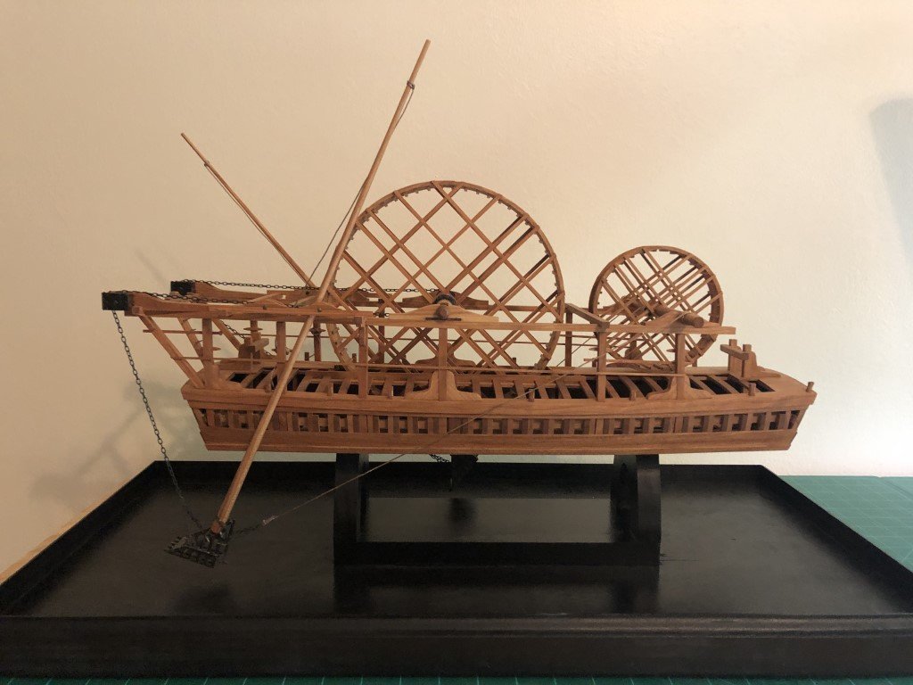
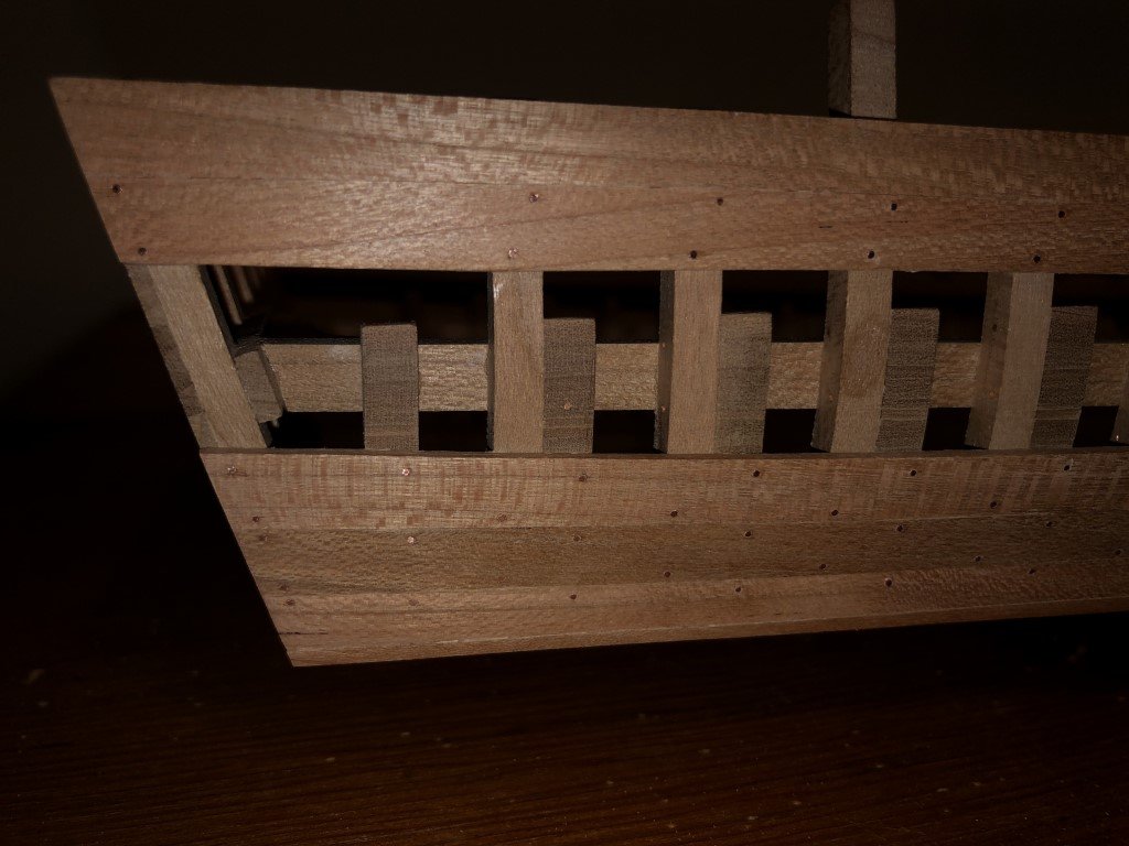
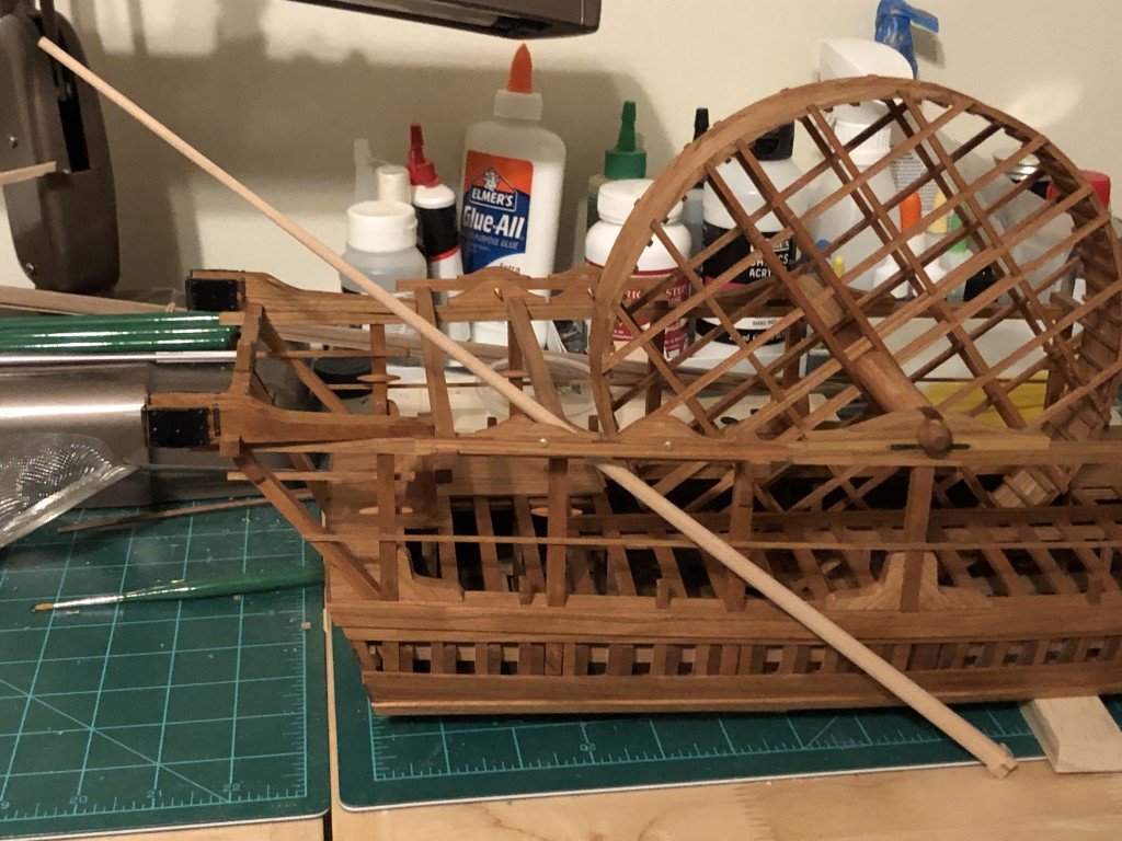
I do have a well equipped model shop and enjoy scratch building as well! Here are a few pictures of a 1:36 scale model of a 1750's French dredger I built from ANCRE plans a couple of years ago. It was made from cherry that I milled specifically for the project. All the 'bolts' are copper wire, and the remaining metal work (including the scoops) are brass.

-
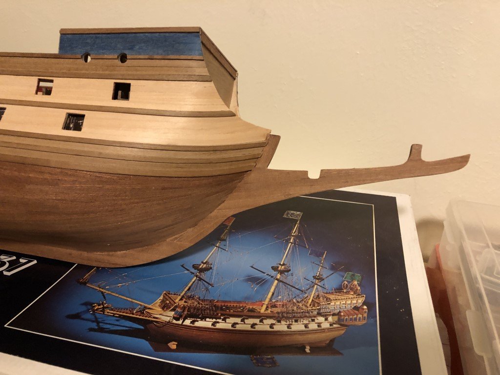
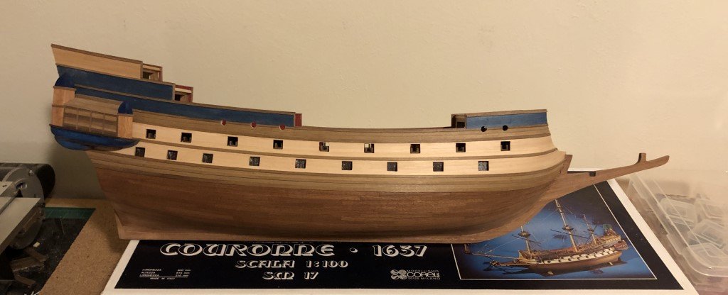
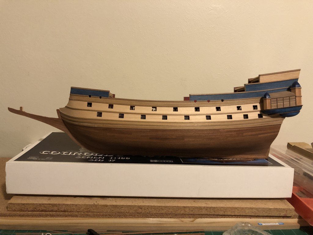
The stem and keel are now completely 'planked'. As expected, the result is OK; but I'm still going with Corel could have included solid would for these features! It certainly can be done as an example, Constructo has found a way to do so and for the most part their kits are less expensive. Time to start adding deck and interior details - then onto the part I'm most looking forward to: the masting and rigging :).
-
Still it seems there might be a good option for kit manufacturers and/or after-market opportunity here to sell upgrade packages - replacement keel structures / planking material / blocks / rigging material for specific kits. Analogous to PE upgrades for plastic models. I would guess that builders of a kit such as La Couronne would dish a couple of hundred for a set of upgrades in one box - the right number of higher quality blocks, ample amount of good rigging line, better wood package, etc. - without having to look around and sourcing everything individually.
-
Started some work up front - the stem was added and now I am 'planking' the stem and keel. It should look OK when done, but if I could go back in time to the start of this build I would have replaced the stem / keel structure with solid wood. Quite frankly, I do not understand why many kits haven't been improved / updated to have solid wood showing in these locations instead of plywood. I don't think it would cost the manufacturer / consumer very much to do so and it would be a nice improvement to a lot of kits.
-
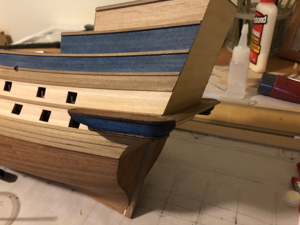
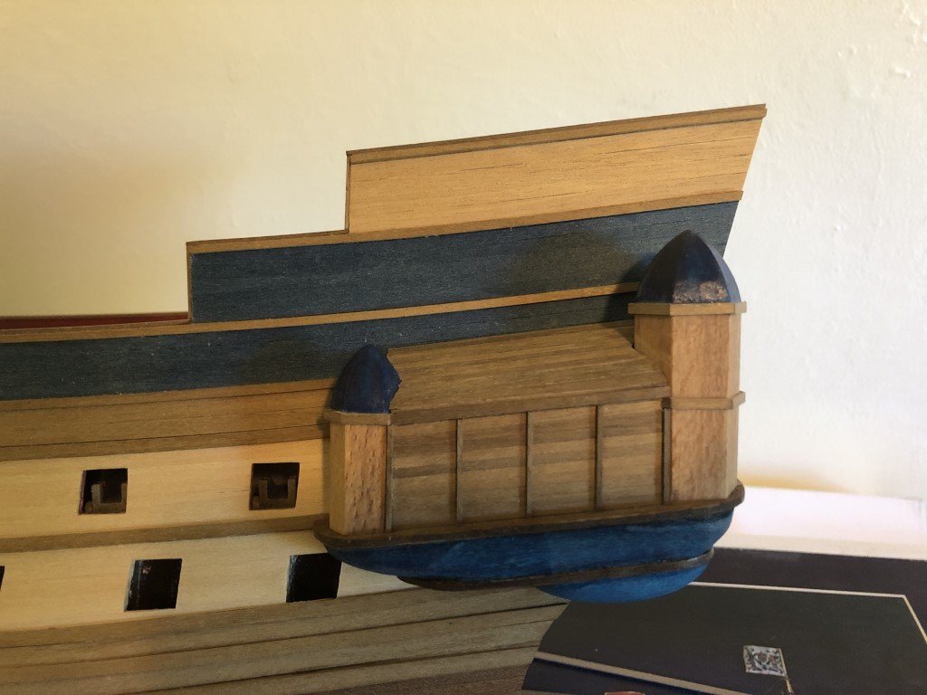
A bit more progress on the galleries.
-
Kurt - Thanks again for all of the helpful information. I actually spent a good deal of time earlier this week looking at your work on the Ships of Scale forum - great work! Greg
-
Thanks! I have one of their monographs - Le Phenix - that is quite nice, so I expect the one on La Couronne is equally well done. If I were at the start of this project and/or was more advanced in my modeling sense when I did begin it, then I would certainly procure the AAMM monograph for guidance. But now that I am so far into the construction, I think I am going to take a pass on the monograph and stay close to the kit instructions for the rest of the hull. I will probably make a few corrections / enhancements when getting to the masting and rigging and perhaps at that point I will rethink the value of getting the AAMM monograph. But even there, I may not need to given the wealth of period information in several ANCRE monographs I have. Actually I am quite fascinated by the Le Phenix monograph and (someday) hope to use the AAMM monograph together with the ANCRE publications 'Album de Colbert', 'The Three-Decker of the Chevaler De Tourville - 1680', and 'The Ships of the Sun King' to build a 1:48 scale framed model of Le Phenix.
-
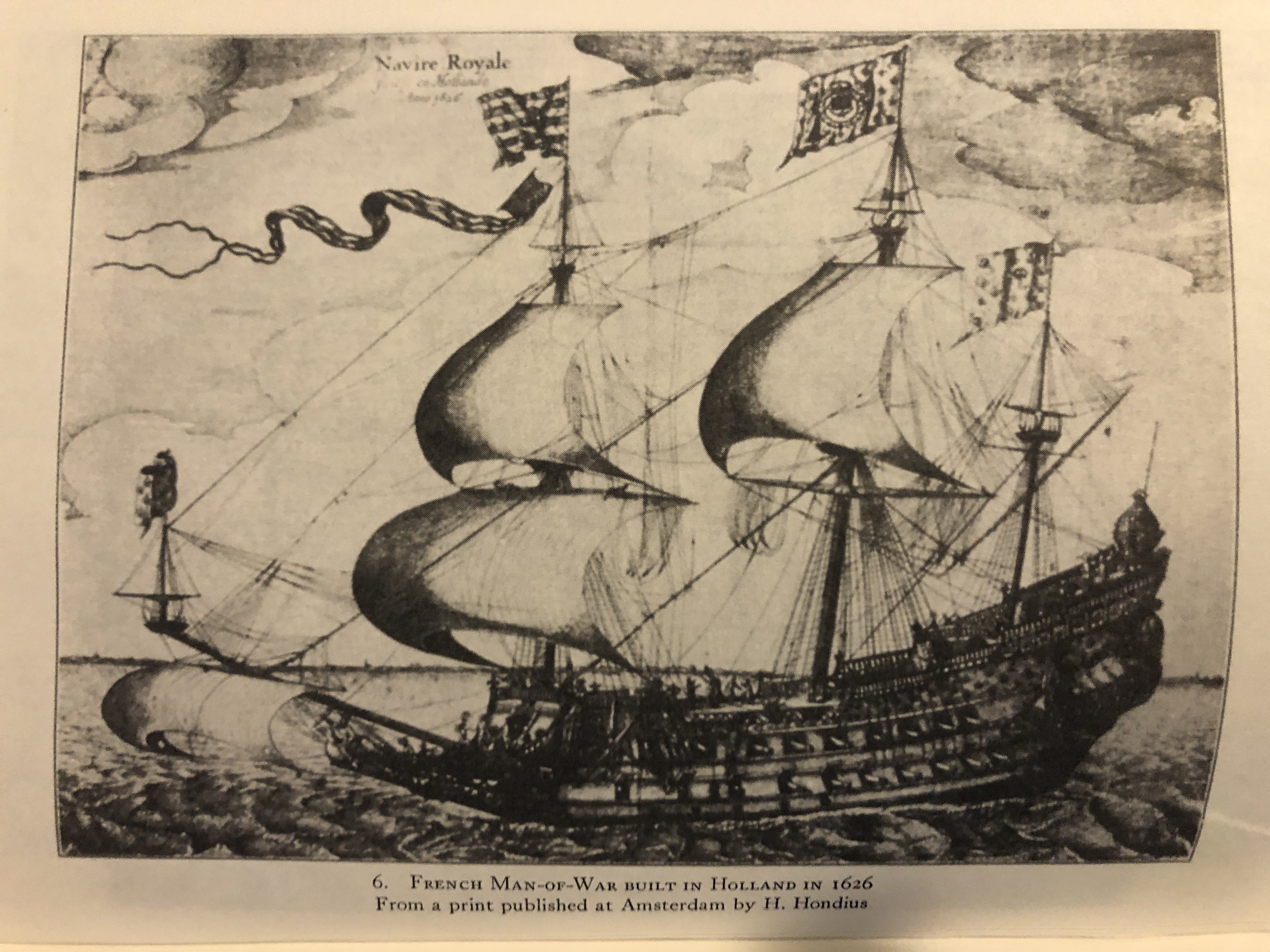
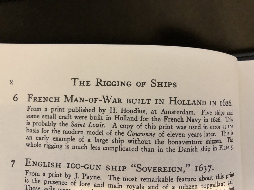
Kurt- That is an interesting picture - particularly because it helps me understand a comment in R.C. Anderson's book 'The Rigging of Ships in the Days of the Spirtsail Topmast, 1600-1720'. In some ways, both ships in your picture have aspects of the Corel model! I have a few ANCRE books related to French ships around this time period and am disappointed that La Couronne is barley mentioned. Since the ANCRE books are very well researched I have begun to wonder if there is very little knowledge available for La Couronne and what is available does not have collaborating evidence. However, in this particular case, I very much like the lines and decorations of the model so I am more than willing to complete the model and view it as a representative of the time period - even if many details (and possibly the name) are conjectural. In particular, I am looking forward to having a go at rigging a ship from this time period. But mine will be sail-less - there is no way I am going to try to duplicate the impressive rigging, and sail making, that you did in your model. I read your build log on Ships of Scale today - magnificent! I too would like it if there is time we would meet up to talk shop. Greg

-
I've started to form the stern galleries. Quite a bit still to add!