Greg Davis
-
Posts
807 -
Joined
-
Last visited
Content Type
Profiles
Forums
Gallery
Events
Everything posted by Greg Davis
-
 Maybe a scratch build project!
 -
I used single strips of wood for the first three strakes below the sheer. This area of the ship will be pierced by a large number of holes - gun ports and oar ports. There will also be two half round moldings added to this section. Because of all the additions (and subtractions) I thought the planking would hold up better with a minimal number of butt joints in the region. Also, with the 'business' of this region, the joints will likely not be missed from a visual perspective. Now moving down the hull, I've marked out two planking belts. Each will accommodate 9 strakes. These are being set in with 8cm long planks. Typical strakes will have 5 planks each of the 4mm wide planking material provided in the kit. The supplied wood is quite nice, a great feature of the kit.

-
By 1910 (in his mid-thirties) SD's health was starting to fail, symptoms and then diagnosis of multiple sclerosis - Its also suspected that SD suffered from bipolar disorder. The last 20 years of his life don't seem to have been particularly good ones. Its clear he had a level of regret that planes were so quickly weaponized. If times and his health had been better, I expect he would have continued his exception line of applied research. Very sad as to how he went from such great highs in the early 1900's to committing suicide in 1932.
-
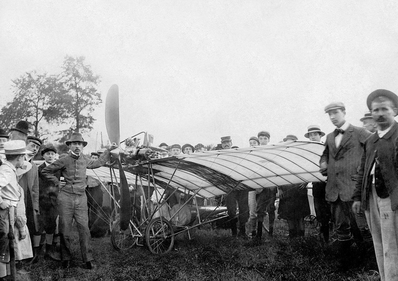
I don't know, his next plane the No.15 had a similar bi-plane large dihedral wing system and now the box canard was in the rear and the propulsion changer from pusher to tractor. He also lowered his center of gravity by sitting just on top of the bottom wing. This plane wasn't successful, perhaps due to an extremely narrow wing chord - reportedly about 2ft - that couldn't have produced a great deal of lift at the low speed possible by the craft. Perhaps this was why it didn't successfully fly. His next airplane the No.17 is reported to have been similar to the No.15 and is not well documented. It is claimed that this plane went untested. His final sequence of planes - the Demoiselle sequence - were all small monoplanes where the pilot sat over the landing gear under the wing. This was clearly his most successful design - I feel it has a number of 'modern' aspects to it. I have no idea if the design is all his and/or it was a natural assimilation of current designs. It is also impressive that he let plans for the Demoiselle be published (in Popular Mechanics) so anyone interested could build one. I understand that the Demoiselle plans are the only SD plans that exist, the rest having been destroyed after the French had accused him of operating as a German spy. This picture shows Santos-Dumont with one of the later Demoiselles (with a pretty nice prop!).
-
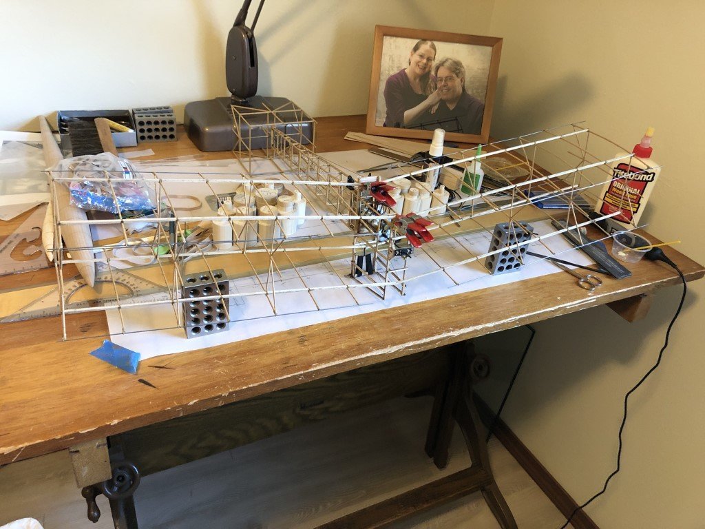
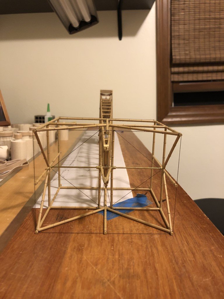
Today I decided to permanently attach the wing panels This is completely out of order from the instructions - I hope its not a bad idea, but I just 'felt' it was time! The instructions suggest that the landing skids are first attached to the wings and the fuselage as well as the wheels. Then, to set the dihedral 1.5cm shims are to be put under the wing skids. This minimally assumes that the skids are both the same length and don't flex to much when being used as supports. Here I have set the dihedral using a pair of 1-2-3 blocks while the fuselage / canard assembly sits solidly on the work space. The downside is that the whole structure now becomes more unwieldy as the time comes to adding the skids and other objects. I'll also be adding bamboo diagonal reinforcements to installed wings at a time I can't move the structures as freely. The way I interpret the instructions, wing rigging was to be done before wing installation. I don't think that it will be that problematic to add it with wings in place - certainly not as challenging as rigging a ship. As George alluded to, once the wings are added the model does take up a good deal of space. So now I'm back to the question: where does this thing go when its done? My wife thinks it would look good hanging from the ceiling and I'm thinking a flat mount onto a wall could be interesting.
-
That certainly could be the case - it might even be a better description for this craft than hydroplane!
- 288 replies
-
- 3
-

-
- Santos Dumont No. 18
- hydroplane
- (and 1 more)
-
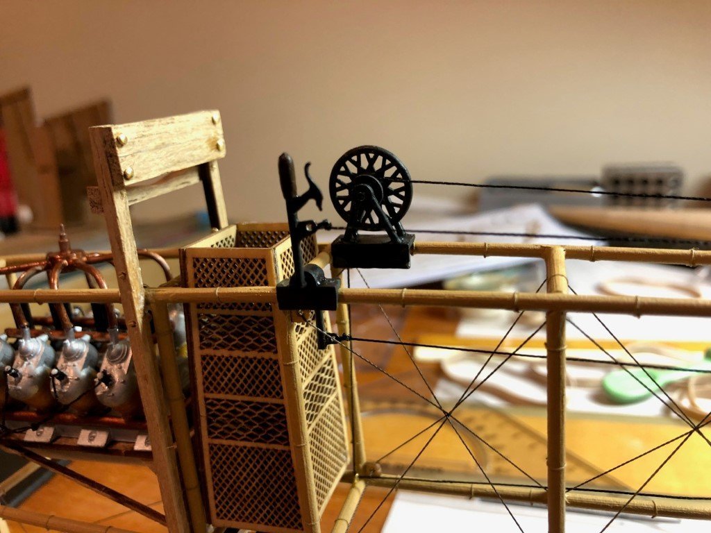
I've added and rigged the canard controls I blackened all the metal parts and then painted the handle of the lever brown. This work didn't go as well as it should have. I broke one of the support legs on the wheel control as I tried to bend two of the legs to be a little closer together and thereby match notches in the base. Fortunately the repair looks fine. I wanted to note that there is a hole in the base (close to the basket) for the control line to pass thru and down to the bottom of the fuselage. In order to keep the hole from being blocked the base needs not to be pushed tight to the fuselage stringer. After gluing the lever assembly together, I congratulated myself on applying some petroleum jelly to the horizontal part of the lever in order to assure free movement - but then noticed the base was reversed from what it should be. The glue join was really strong and I decided not to dissolve / disassemble the joint - I'm sure this is the way Santos-Dumont had wanted it assembled originally and the actual error was on the real plane. I had to toss the supplied rigging line for the control lines as it had a number of snags and I couldn't get a long enough piece to do the work - so a quick trip to the local stash of extra materials. The controls actually move the canard up/down and right/left. I think that before the model is complete, I will restrict all motion to prevent overuse and/or breakage. I typically think that static models should be static!
-
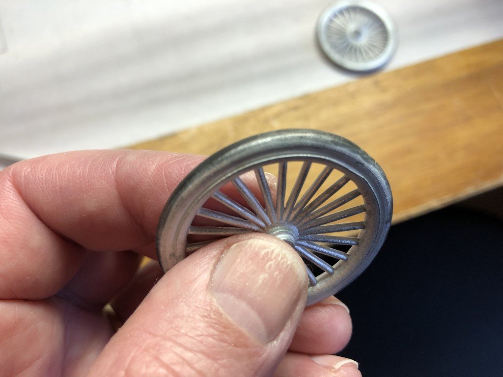
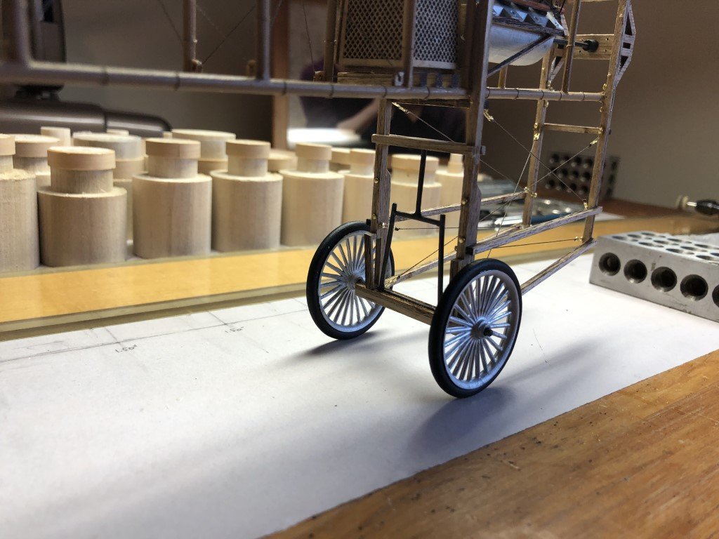
I started working on the landing gear - the instructions indicate that this should be installed before the wings are attached (and that is getting close now). Still disappointed that the tires are part of a casting and not rubber. I was afraid that paint on the tires would easily rub off if the plane was rolled over nearly any surface. Because of this, I decided to blacken the middle part of the tires before painting them black. If (when) the paint comes off, the blackened metal will take over! I brushed blackener onto the tires, let them set a few minutes before rinsing them. After drying the flat black paint was applied. I also used blackener to color the landing gear axle assembly. The wheels are not permanently attached at this point, before doing so I will add the 'rubber' suspension system to the landing gear.
- 162 replies
-
- 10
-
-
Congratulations!
-
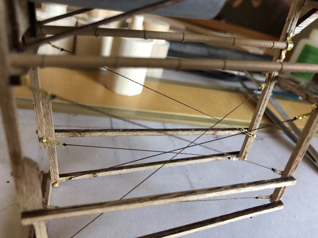
I installed the nails backwards. I put the turnbuckles on the pins and a drop of CA on the end of the pin before pushing into place. Just needed to be real careful about slanting the turnbuckles correctly as soon as the CA sets they don't move anymore! Also they are really easy to bend in a way that in not intended.
-
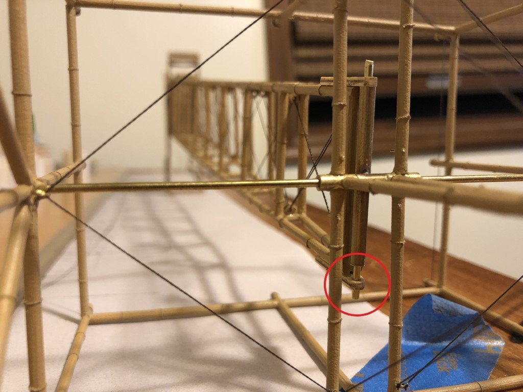
I have the canard trial fitted / lined up square with the fuselage. It turns and rises / lowers nicely. Should be interesting to see if I can get it rigged to the cockpit controls later - they are suppose to be functional. Here's another place where a beta modeler may have been able to provide feedback to make the canard fitting a bit less sloppy. Note how the 'canard axle tube' doesn't reach fully between the two canard supports. If the tube had been about 3mm longer, there would still be free movement but a much more professional fit. Later, during the final attachment, I may fit a pair of 1.5mm washers to fill in and balance the canard installation.
-
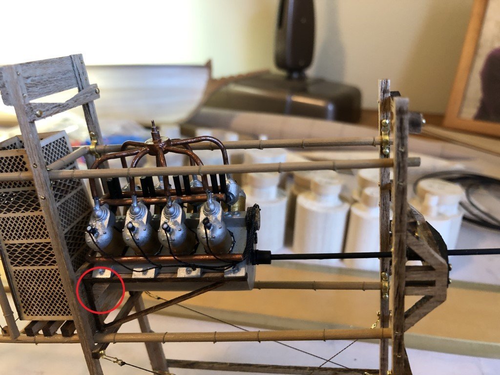
Sounds good - I hope the engine / mount slide in nicely. By the way, during one of my trial engine fittings I had the top part of the engine support detach from the vertical strip. After putting it back together, I decided to add a couple of triangular corner gussets to help support the joint. Even before this happened I was concerned about the butt joint being able to support the engine. I would guess that in the original plane, the joint was likely rabbeted and a lot stronger than how the model is designed. Also, when it comes time to install the wings, there is another part that is not mentioned in the instructions. There is a middle rib that needs to be added at the joint between the wing panels. You can see a bit of it on the plans - a lot of the rib is concealed by the fuel tank. You can also make it out on the prototype model in the pictures on p35 and 36 of the instruction manual. I wish Model Expo had secured a third party beta model builder to make this model and provide edits to the instruction manual before the kit was released to the public.
-
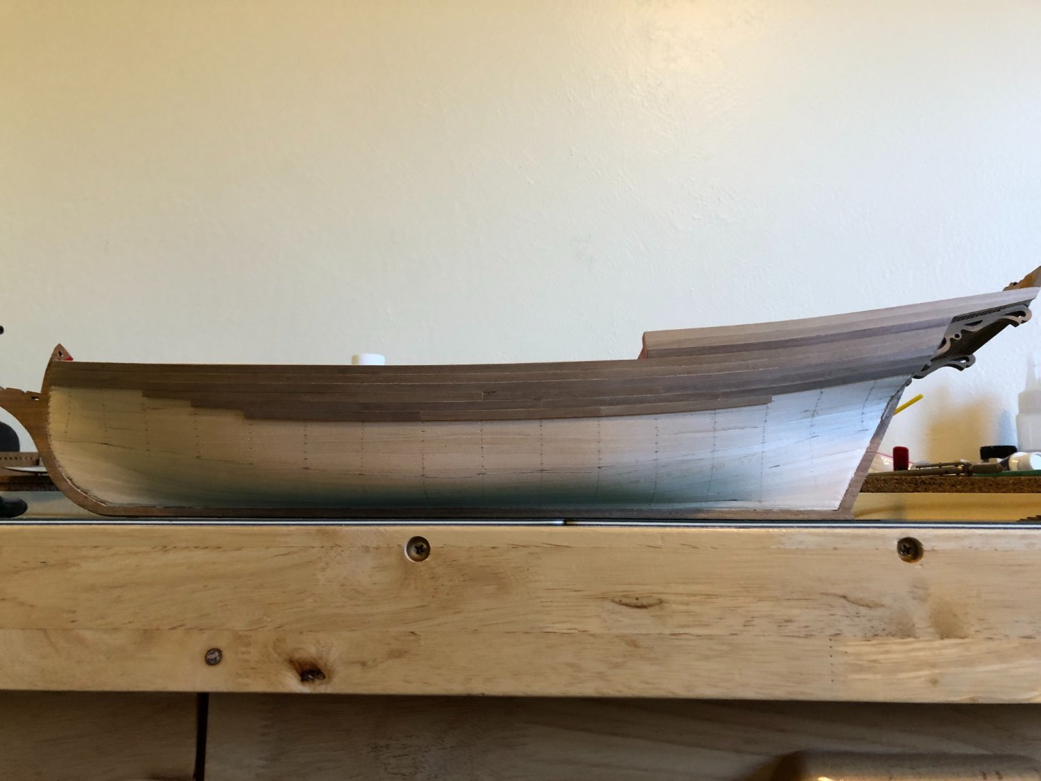
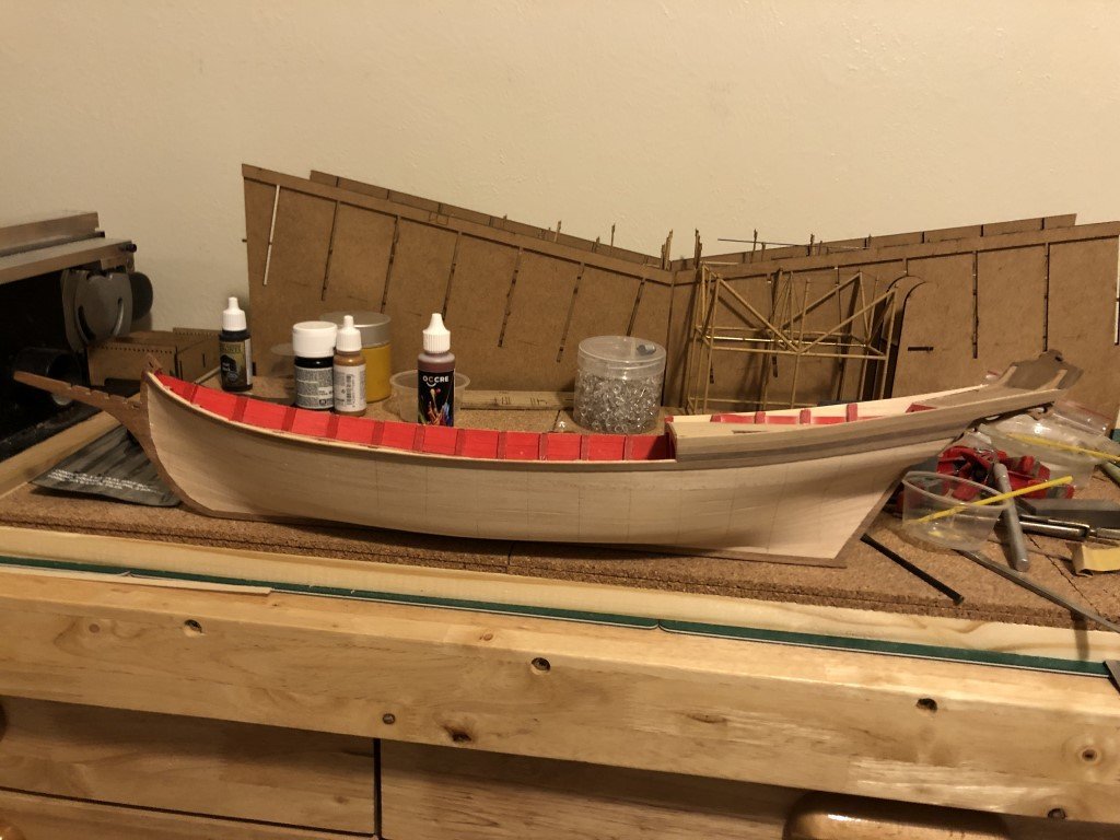
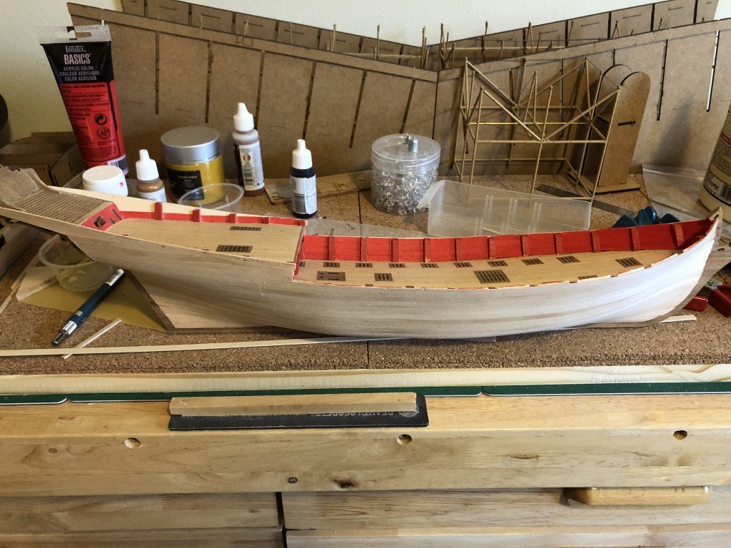
I've had time to smooth out the first layer of planking and started to attach the second layer. The sheer has been adjusted as well - I find this type of ship to be very gracefully designed.
-
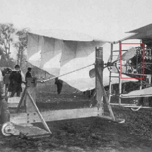
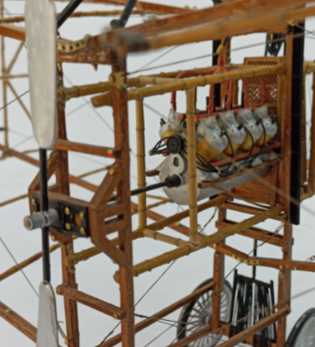
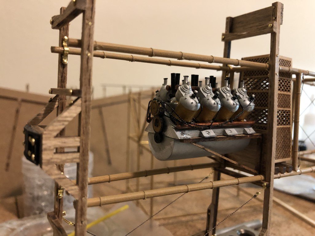
The engine is done! The propeller shaft is attached now but the propeller will not be added until much later. A set of bamboo crossbeams need to be added near the front of the engine. These crossbeams can be seen in the following (interesting) picture were a hand cranked engine starting mechanism has been attached to the 14bis. Note, the crossbeams can be located on the big plan of the model, but are not mentioned in the instruction manual. They are shown in the pictures of the porotype model on the ME website:
-
Nils - It wasn't designed for flight - it was a watercraft. In a couple of well regarded biographies and on some web sites there is a misrepresentation of the No18 hydroplane. It seems that in the early 1900'sthe term hydroplane had at least two meanings - the predominant being that of an airplane that could rise from water, like a float plane; the other, that of a boat that skims the water surface like a modern day hydroplane. I imagine that the Santos-Dumont biographers that have made the misrepresentation were so focused on his role in developing aircraft that they may not have even realized that No18 was a boat. Unfortunately, this kind of a mistake in the biographies makes me wonder a bit about other information that they have written / repeated about him! Greg
- 288 replies
-
- 7
-
-
- Santos Dumont No. 18
- hydroplane
- (and 1 more)
-
Craig - The step down idea is great, as is using some CA to make nicer holes! I was also thinking press fit so that the smaller disks could be slid inward where the pontoon diameter is greater for easy removal when it is time to disassemble. Once the stringers are in place there might not be enough room for cutters to get to the dowel. Instead I was envisioning using a jewelers saw to cut the dowel. I'll need to provide some protection to the stringers in the region the cutting is done, maybe some thin brass sheet slid under where the cuts are. Thanks again, Greg
- 288 replies
-
- 3
-
-
- Santos Dumont No. 18
- hydroplane
- (and 1 more)
-
Craig - I thought about a shaft also but wasn't sure if it was needed. The more I think about it, the better the idea gets! The shaft can't be too big in diameter when it gets to the terminal ends or it just wouldn't go thru the smallest two disks. I don't think I could use more than an 1/8" diameter dowel. On its own the dowel wouldn't be stiff enough to be useful, but in conjunction with the supports it would likely do a good job. I could place rubber bands over the shaft to keep everything seated as well. A small diameter shaft should not be too difficult to cut into segments when it came time for removal of disks and shaft. I can bore the disk center holes via the tailstock on the lathe at the same time I'm parting the hoops / disks. Thanks for bringing this option up! Greg
- 288 replies
-
- 4
-
-
- Santos Dumont No. 18
- hydroplane
- (and 1 more)
-
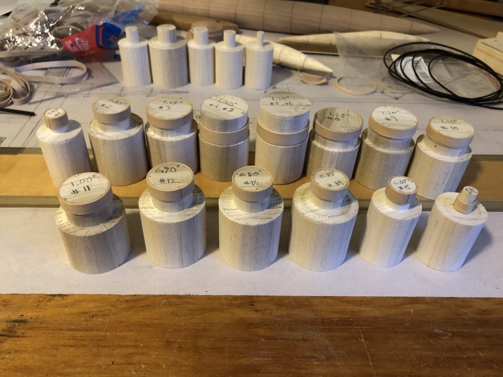
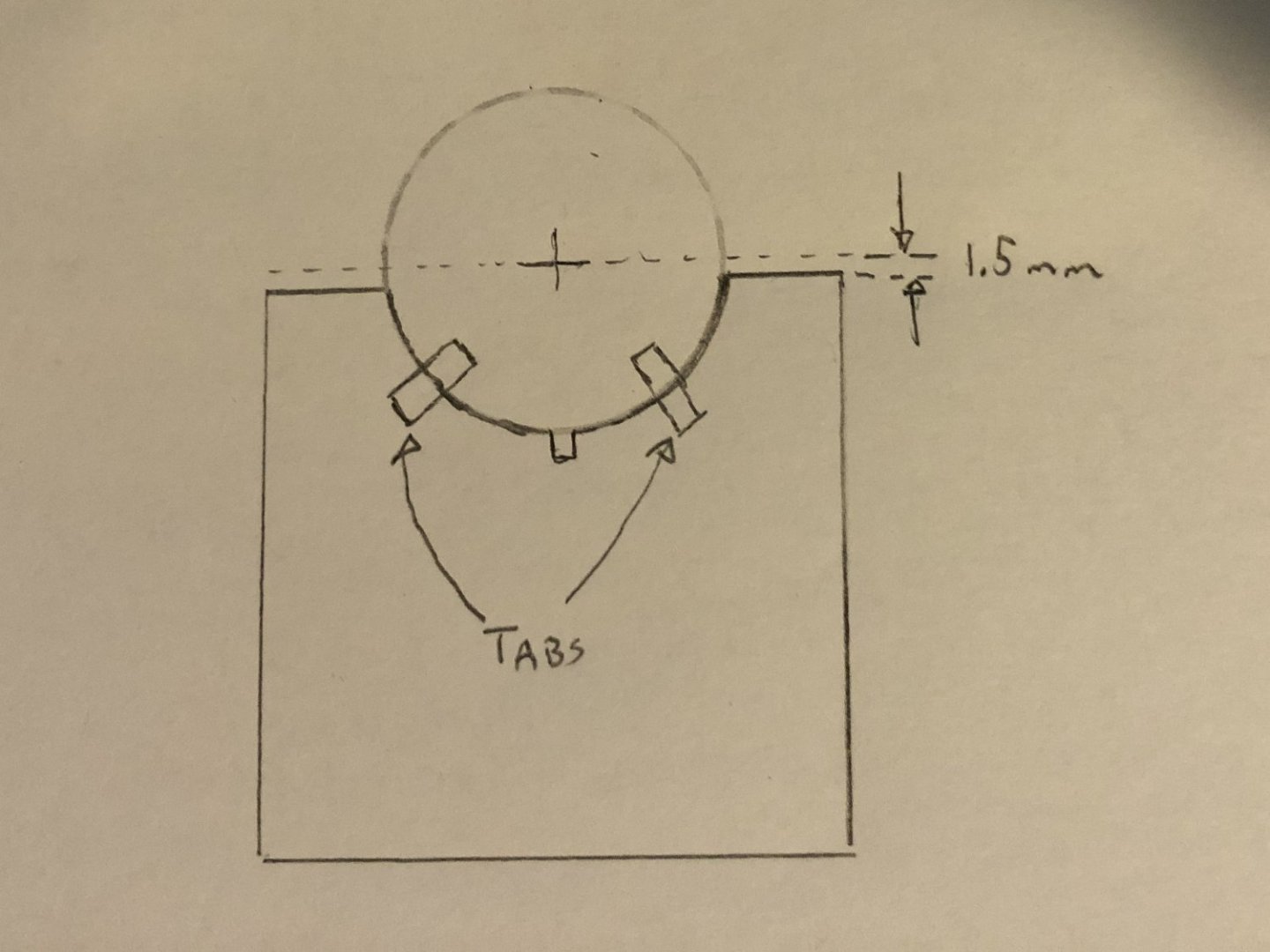
I have all of the hoop material for the main pontoon laid up on the formers. Three ply's for each. They were not too difficult to set up until the diameter dropped below 0.5" - the smallest one 0.30" was not fun. I'll part off 3mm hoops on my lathe. Most I only need to cut one from but there are two pairs of hoops #4 & #7 and #5 & #6 that have the same diameter. For those I laid up wider strips of wood so that I can part two off each. Still thinking about an assembly jig. This is what I am currently thinking of making: There would be a 16 pieces of 1/8" hardboard cut to the above shape - one for each hoop. Each riser would be be made with the center of each hoop at the same height. The semi-circular cut out for each hoop's out diameter would top out 1.5mm lower than center to accommodate the 3mm side stringers. A notch would be cut at the bottom to accept the bottom (or top) stringer. To help keep the hoops stabilized thru the stringer installation, I will slice off a 3mm disk from each form to sit inside each hoop. This way I can press down / clamp the stringers without fear of breaking a hoop. A couple of tabs on each riser should keep the hoops / discs vertical. An alternative would be to cut a more standard comb jig and keel support like those used for typical scratch built framed ships. For some (unknown) reason I'm more worried about getting all the necessary alignments to get the symmetrical / linear cigar shape. Input certainly accepted!
- 288 replies
-
- 11
-
-
- Santos Dumont No. 18
- hydroplane
- (and 1 more)
-
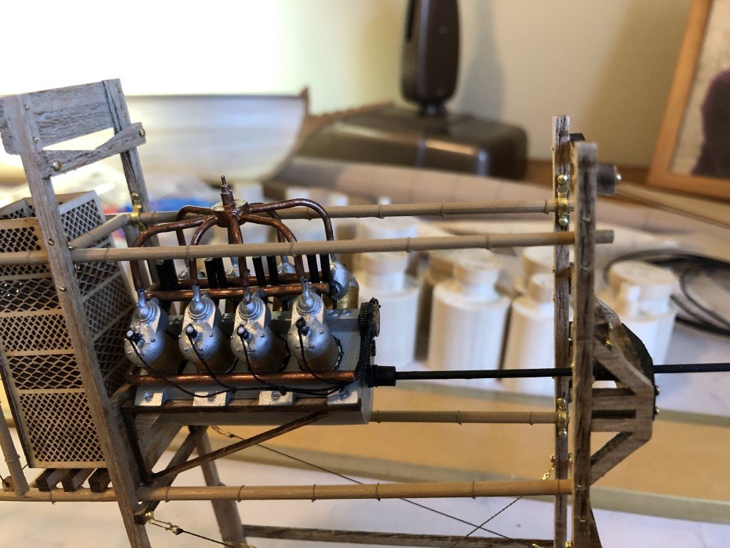
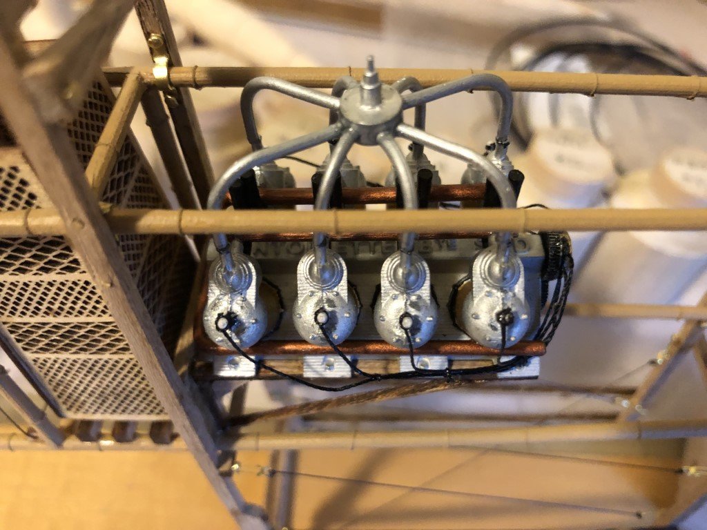
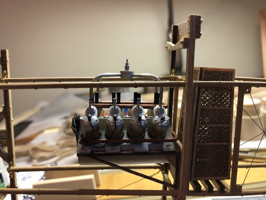
Just finished installing the fueling tubes to the middle four cylinders - pretty tedious work. Now it needs some copper paint to be finished with the engine installation.
- 162 replies
-
- 11
-
-
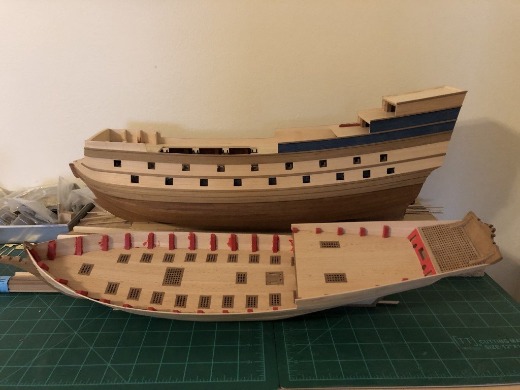
I hope there are no limits on the number of build logs one can have open at any particular time! I'm trying to make more bench space to get back to may 'main project' - a scratch-built model of L'Invention 1799 based on G. Delacroix's amazing ANCRE monograph. Unfortunately, I have a problem with starting models and not always finishing them directly. So lately it had been pointed out to me, by the resident space allocator, that I don't need more space, I just need to finish a few projects to reclaim the space I need. I concede that this is a truth. There are at least two models, well along that could / should be finished. Once done a good deal of space will open up again. This is a picture of the two as they sat a few days ago: In the back is the Corel model of La Couronne that I purchased in 2011 and started in 2020. In the foreground is the Amati model of the 1753 xebec Sciabecco; purchased and started in 2015. With the help of this log, I hope to make some steady progress and finish the Sciabecco in tandem with my Santos-Dumont 14bis airplane kit build and my Santos-Dumont No18 Hydroplane scratch build project. Big hopes, but I figure something a retired person can achieve. Unfortunately, I don't have any photographs of the early stages of the Sciabecco build so I will try to provide some background in a written form. I believe the key aspects wood be that The plywood keel assembly was replaced with one made of cherry so that the ply's in the stem and stern would not be visible when finished The lower deck was extended / planked past the gratings on the upper deck The gratings were glued to the false deck prior to planking and then sanded flush with the deck. The instructions call for the gratings to be added on top of the deck planking. The large stern grating is made from cherry (this was my first try at making my own grating) and replaces a plastic grating that had spaces too large for the model. Over the last couple of days I have been adding the quick stuff to the bulwarks and getting this material painted to match the interior paint. The first layer of planking was pretty well done, so it shouldn't take much time to prep the model for the second layer. It may get up to 50 degrees (F) here tomorrow - that would be just fine to sit out back for a while and smooth out the hull. At some point I'll open a log for La Couronne - it will be great to get that one done also. I really like the rigging of that time period.
-
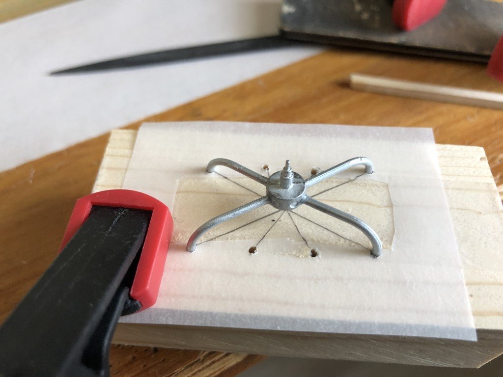
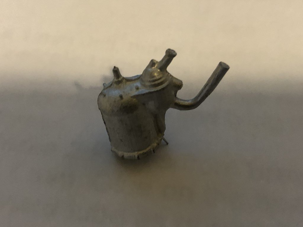
Yesterday I made a small jig to help assemble the fuel distributor. First I marked the pattern of where the parts would attach to the engine by placing a small sheet of vellum over the cylinders on my engine. I then taped the pattern to a piece of wood and drilled 1/16" holes where each tube would go. Figured out where each of the eight tubes were to fit (not quite the way the instructions seem to indicate). As with George's experience, the castings needed to be reduced a bit (close to 1mm) to fit the carburetor(?) correctly. Also it might be noted that for the pieces to come together correctly, the carburetor needs to be aligned with its casting molding line parallel to the engine block. At first I was going to put all 8 fuel tubes in place using the jig, but then I got worried about pulling the assembly free so I stopped at the four longest ones and waited overnight before extracting the assembly. I then fit this assembly to the top of the engine. Two of the fuel tubes needed to be shortened for the assembly to sit level on the four cylinders. I also needed to make a few small adjustments to get a better alignment of the tubes to the cylinders. Through a series of very small bends using two pairs of pliers I got everything to match as best possible. And just as George said - working on this assemble is a royal pain! At this point I decided to permanently attach the engine to the engine mounts and then attach the partial fuel system to the engine. I'll fit and install the remaining four tubes with this much in place.
-
George - Completely understandable - I totally understand where you are coming from! Good luck! I received the (no longer needed) cockpit parts in the mail today, so it will undoubtedly be the case that yours arrive soon. Greg
-
Looking really nice! I would give your idea of putting the engine in place and then closing up / finishing the backend some thought. My initial thoughts considering the pro's and con's seem to be having to disassemble the fuel system vs having the backend of the plane heavy as you rig the undercarriage / complete the nacelle. I found that undercarriage rigging to be a little challenging because the brass turnbuckles are really fragile. I had to come at the work from a lot of angles and appreciated that the structure was light weight at the time. If you can get the fuel system off in one piece that may be the 'safest' way to go. Looks like we made similar engine stands!

-
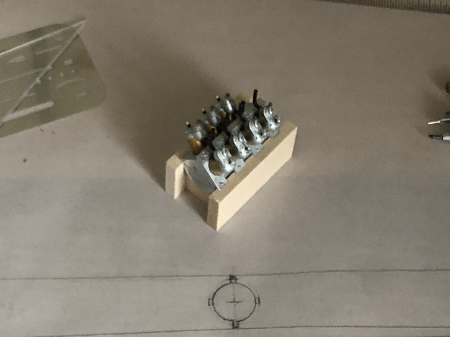
A good portion of the engine is complete. Here it is sitting on the engine mounts, but not permanently attached. The fuel distribution system that goes on top still needs to be built. It needs to be attached after the engine is in place for good because there is not enough room to maneuver the complete structure in place. In fact there is a good deal of tipping and turning just to get this much of the power plant in.
-
Replacement cylinder arrived in the mail today! Time to get out a file to clean it up and then paint it to match the other seven that are already in place.
- 162 replies
-
- 10
-