HOLIDAY DONATION DRIVE - SUPPORT MSW - DO YOUR PART TO KEEP THIS GREAT FORUM GOING! (89 donations so far out of 49,000 members - C'mon guys!)
×


MikeConnectrix
-
Posts
23 -
Joined
-
Last visited
-
 KeithAug reacted to a post in a topic:
DKM Bismarck by MikeConnectrix - Scale 1:150 - 3D printed - RADIO
KeithAug reacted to a post in a topic:
DKM Bismarck by MikeConnectrix - Scale 1:150 - 3D printed - RADIO
-
KeithAug reacted to a post in a topic:
DKM Bismarck by MikeConnectrix - Scale 1:150 - 3D printed - RADIO
-
NavyShooter reacted to a post in a topic:
DKM Bismarck by MikeConnectrix - Scale 1:150 - 3D printed - RADIO
-
Canute reacted to a post in a topic:
DKM Bismarck by MikeConnectrix - Scale 1:150 - 3D printed - RADIO
-
Ian_Grant reacted to a post in a topic:
DKM Bismarck by MikeConnectrix - Scale 1:150 - 3D printed - RADIO
-
yvesvidal reacted to a post in a topic:
DKM Bismarck by MikeConnectrix - Scale 1:150 - 3D printed - RADIO
-
GrandpaPhil reacted to a post in a topic:
DKM Bismarck by MikeConnectrix - Scale 1:150 - 3D printed - RADIO
-
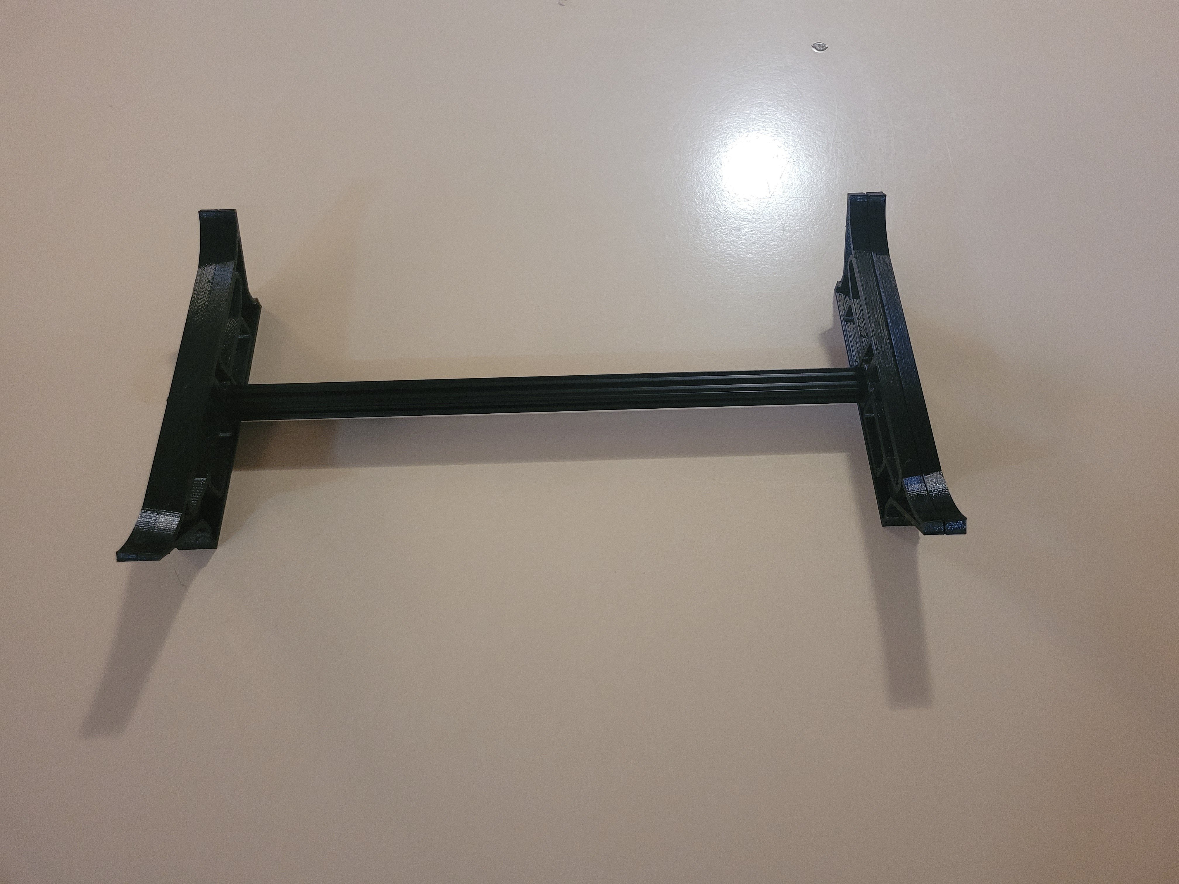
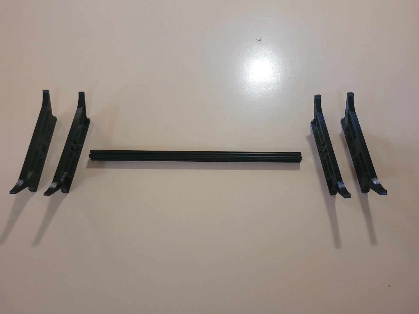
I don't quite know why, but had a section of 15mm T-slot at 395mm lying around, so made the stand based on that. 400mm will work OK as well. The supports are just friction fitted to the T-Slot. You could glue it etc but it's a pretty snug fit and quite sturdy as is. Just make sure the hull profile matches when the sliding the pieces on. None of them are interchangeable. The forward ones are one profile, the rear ones have a different hull profile. I am yet to make a name plate holder.

-
KeithAug reacted to a post in a topic:
DKM Bismarck by MikeConnectrix - Scale 1:150 - 3D printed - RADIO
-
KeithAug reacted to a post in a topic:
DKM Bismarck by MikeConnectrix - Scale 1:150 - 3D printed - RADIO
-
KeithAug reacted to a post in a topic:
DKM Bismarck by MikeConnectrix - Scale 1:150 - 3D printed - RADIO
-
As I said, unique and impressive. Did I hear someone saying you needed a guy with a drum down the back.. Agreed!
-
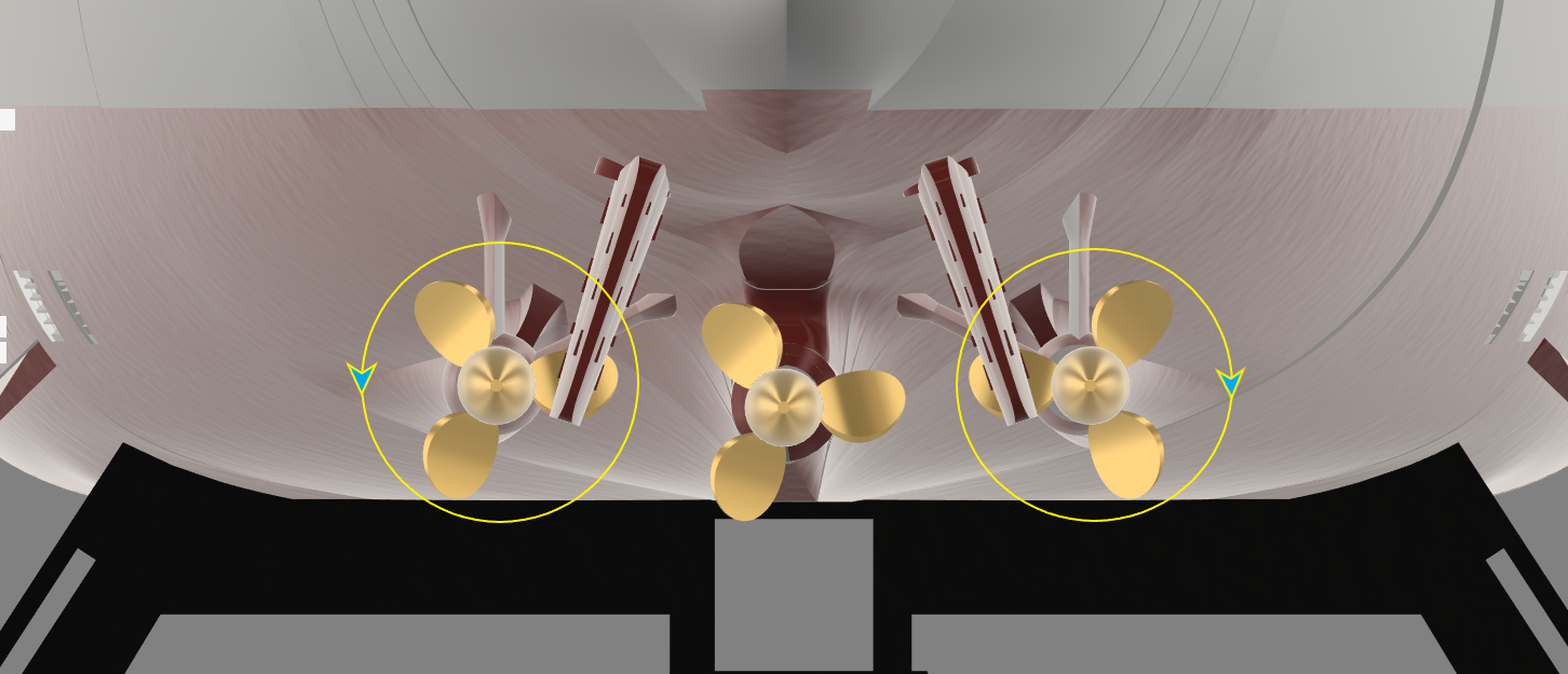
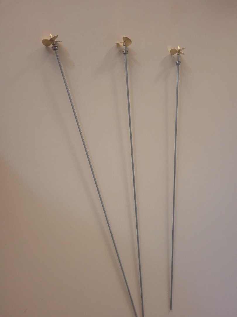
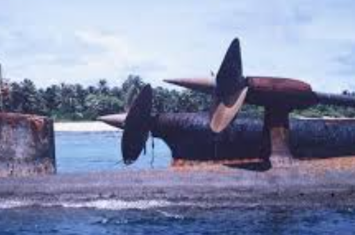
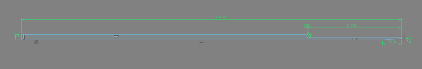
Prop shafts for this I decided on 3mm, although 4mm is an option, with a length around 440mm. An exact length I won't know until I actually couple them to the motors, so I made them 500mm for now. Each outer shaft has 4 F693ZZ 3X8X4 bearings heat fitted to the propellor support and tube, while the centre prop has just 2 of the same bearings for the tube. Doing your own shafts is straightforward but do not try it without a split HSS die (ask me how I know:)). I just did them by hand although I could have just as easily mounted them in the lathe with a die holder. If doing it by hand make sure you use a soft grip in the vice to secure the shaft while threading (Ask me again how I know, mine is just a squashed bit of 10mm aluminium tubing). 3mm stainless rod into 3mm bearings is a heat fitment. Freeze the shafts and put the bearings in the oven and after 10 minutes the bearings just slide right on. I choose to mount the shafts in a power drill and go back and forth with emery cloth to take a poofteenth off the shaft so the bearings slide on and off cold. Alternatively you could probably just use 2.8mm stainless rod. Two of the propellors (32mm) are clockwise with the port screw counter-clockwise. Typically in multi screw naval vessels looking from the stern the outer tip of the blades travel down to reduce turbulence. There are several photos of Prinz Eugen when there were 2 screws on the wreck. The ship is upside down, but the port screw (nearest) clearly rotates counter-clockwise when going forward looking from the stern. Looking at you Steam - Ship Explorer - Bismarck

-
An R/C Roman galley must be pretty unique. Amazing. I'm a software engineer that likes to tinker with electronic hardware. Sadly, I'm not retired yet which means I don't get as much time as I like working on boats. Oh well... The board in that link was made using my own design pick and place machine and is double sided. My lab also has a CNC lathe, Laser cutter, CNC Router, 4 Axis CNC Wire cutting table, SMD Reflow oven and heaps of other stuff that has mostly sat unused for the last year. Customers requirements at work, wife needing heaps done around the house, having fun with grand-children plus a continuing battle with skin cancer took care of all my time this year. I'm unsure if I will put that board up for sale or not. It is finished and the firmware mostly functioning and just waiting for a boat to test it with. It can be emulated with an ESP32 development board, LSM303 compass module, SD card board and a couple of servo expansion boards. Putting a wiring guide on that GitHub page is on my to-do list. But hopefully I will get this boat finished in the next 2-3 months then look at finalising the boat controller. After that I have a 90% completed 1:150 Prinz Eugen on the workbench as well.
-
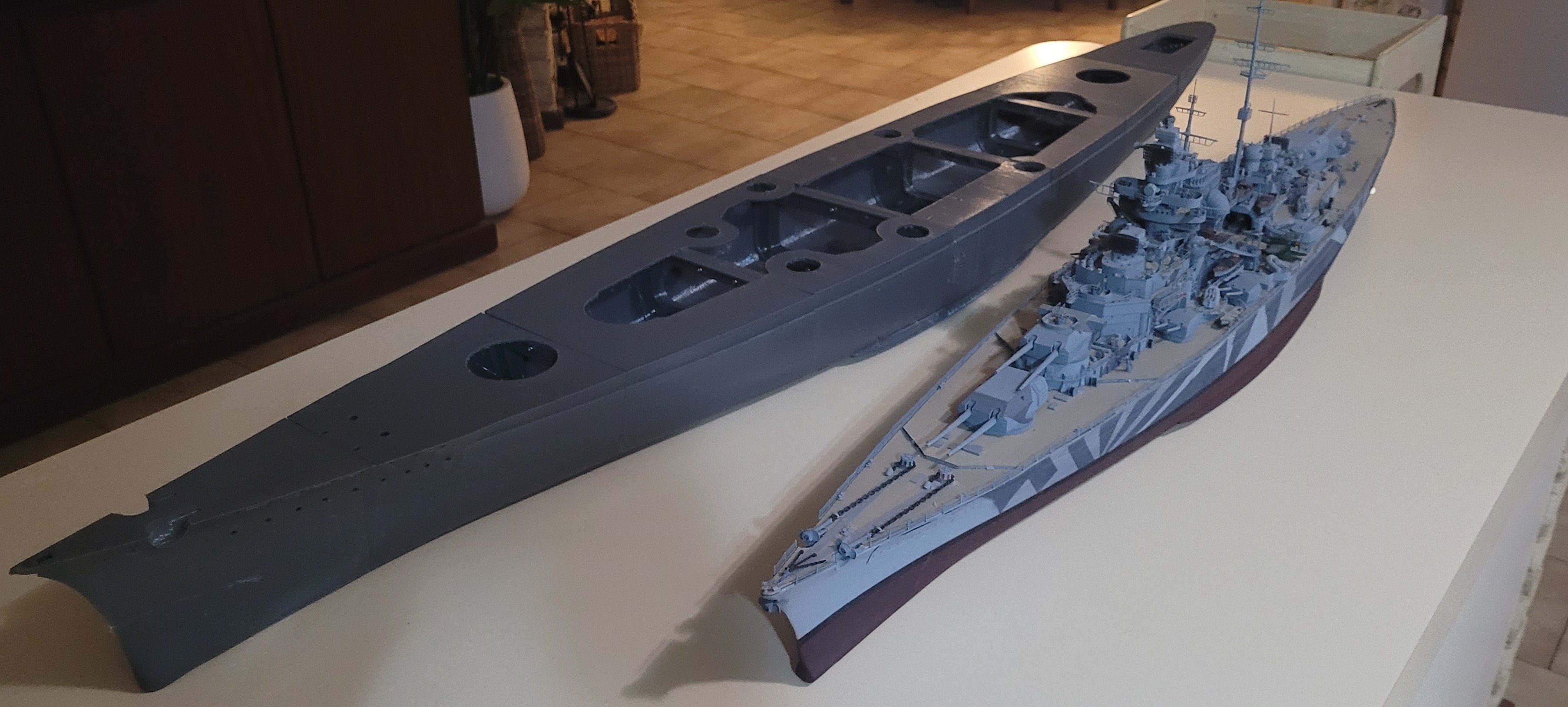
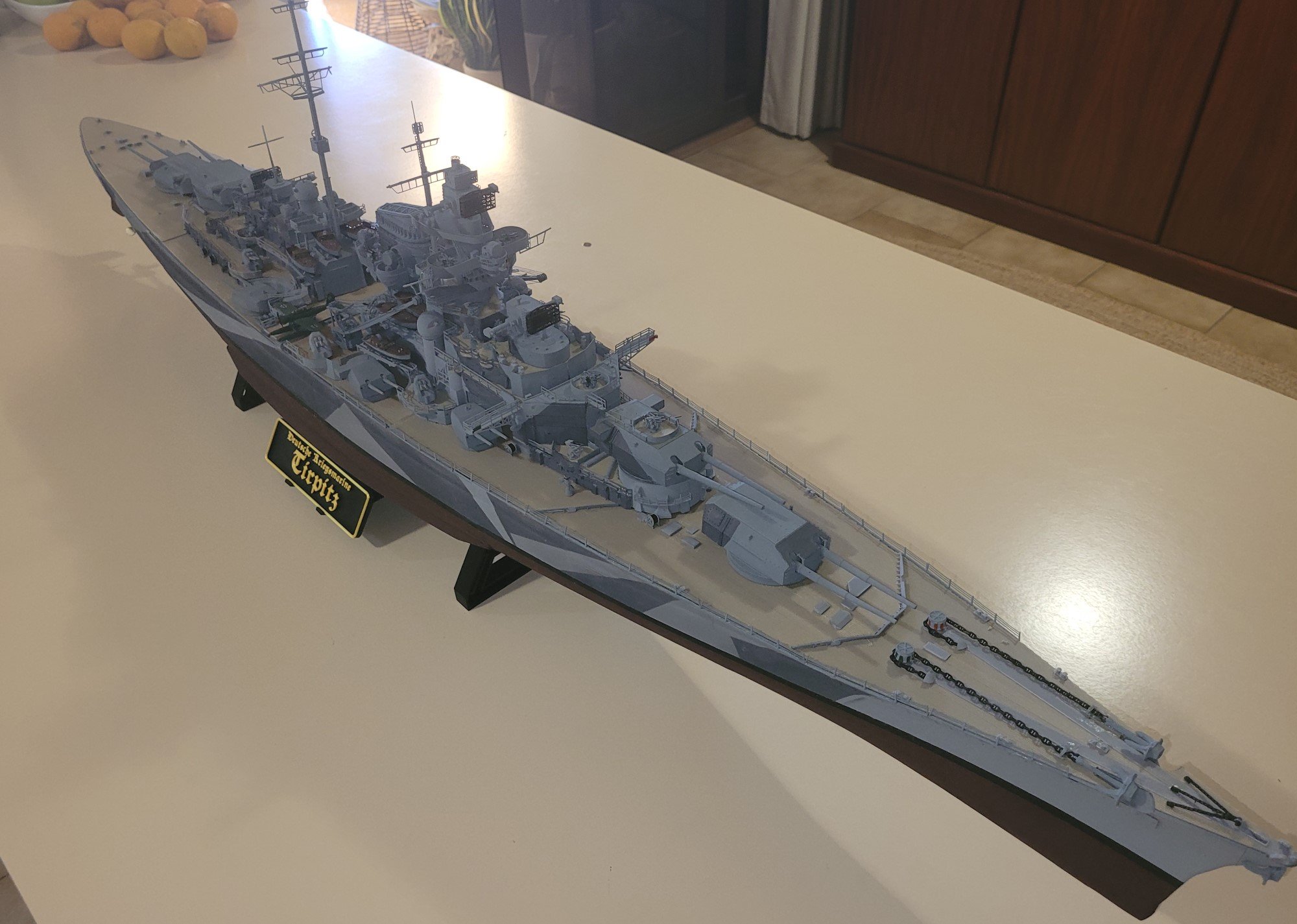
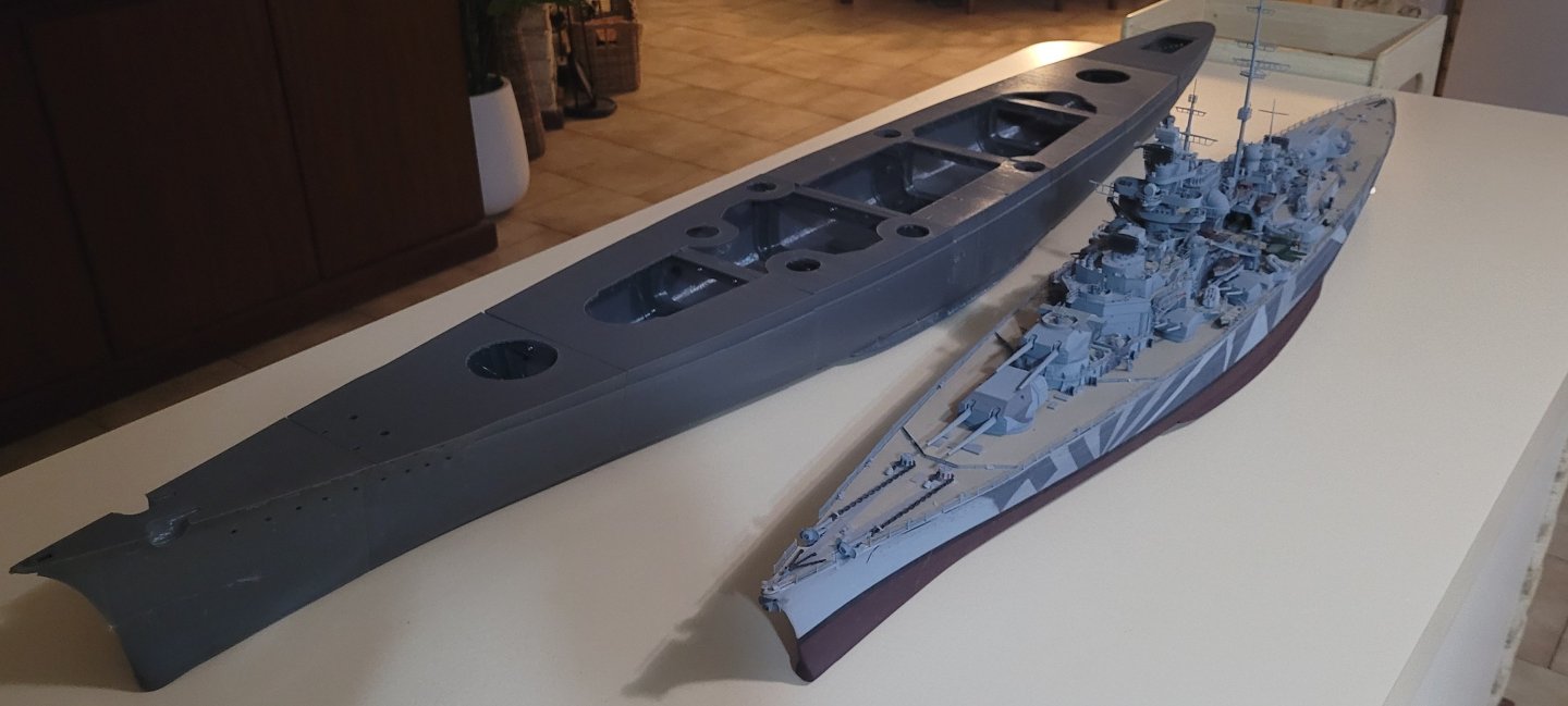
In the lead photo: Tirpitz is 1:200 = 125.5cm=49.4 inches Bismarck is 1:150=167.33cm=65.9 inches Maybe not 30 servos. I can definitely see 27. I will be using a 3 channel controller Rudder/Throttle and Main Fire control director. Everything else will just follow that based on compass input.
-
Hi Ian, A lot of work goes into designing the models so that they print well and look OK. This one will be a mix of resin and FDM prints so its a case of PETG where strength is needed (even though it looks stringy and rough) and Resin print where detail is needed. I printed the hull pieces at 0.3mm layer height so they don't look as good as they could but largely this will be covered with PLA deck veneers and filler/paint. The appearance could be improved by printing at 0.2mm but then your time for each section goes up. I think the longest one on this was 18 hours, but at 0.2 it was over 24. My easy solution to cutting my print times in half was to just build another MK3s One difference between the Tirpitz Model and this model is that the main deck structure is incorporated into the hull files. The Tirpitz model has a tendency to warp until all the deck plates are glued in. This one is rigid as anything and apart from one piece lifting slightly from the bed I haven't encountered too many issues. The turrets are already done, I just haven't detailed them yet. The mains have traverse and elevation, the secondaries just have traverse (considering elevation in the 150's but there is not much room in the turret). All up it will be around 30 servos. The bulkheads/joiners have large apertures in them so passing wiring should not be an issue. I did have an issue with one pair of 150's where the bulkhead is directly underneath it and while I put in relief for the turret into the bulkhead I did not put enough to actually fit the turret. (The servo, by necessity due to the turrets size, protrudes outside the turret basket.) I have since altered the bulkhead file but for this one a dremel was my friend. Mike
-
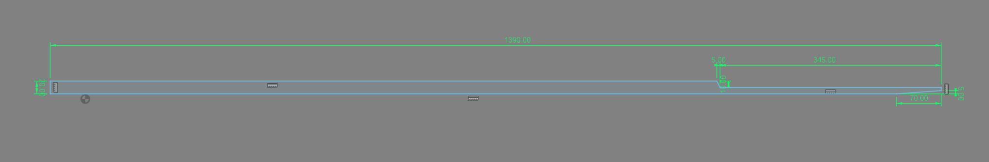
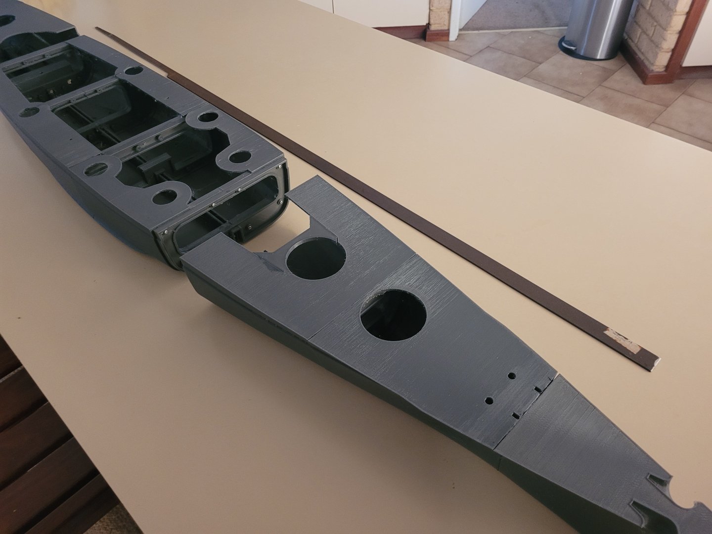
The keel stringer is a simple black steel M3X20mm flat bar with some angle grinder cuts to get the correct profile. Measurements of this are not critical. If its 5-10mm shorter or has the corners rounded to get a comfortable fit it is of little consequence. Weight is not an issue. This thing will need a ton of it to settle at the right level. Here is a pre-oxidised version of it:

-
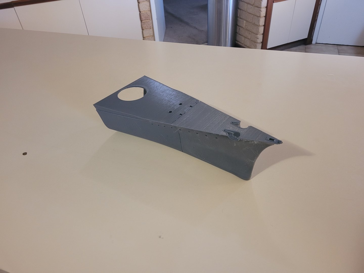
Hulls 4 and 5 were right at the extent of my printers bed in width so I elected to split the pieces with PrusaSlicer vertically using 1.75mm dowel joiners. There is steel keel stringer epoxied into a channel at the centreline when the hull is fully assembled so the chances of this join leaking when assembled is low. Hull 6 Bulkhead has an oil reservoir for the prop-shafts that will feed into the prop tubes which needs to be glued into position.
-
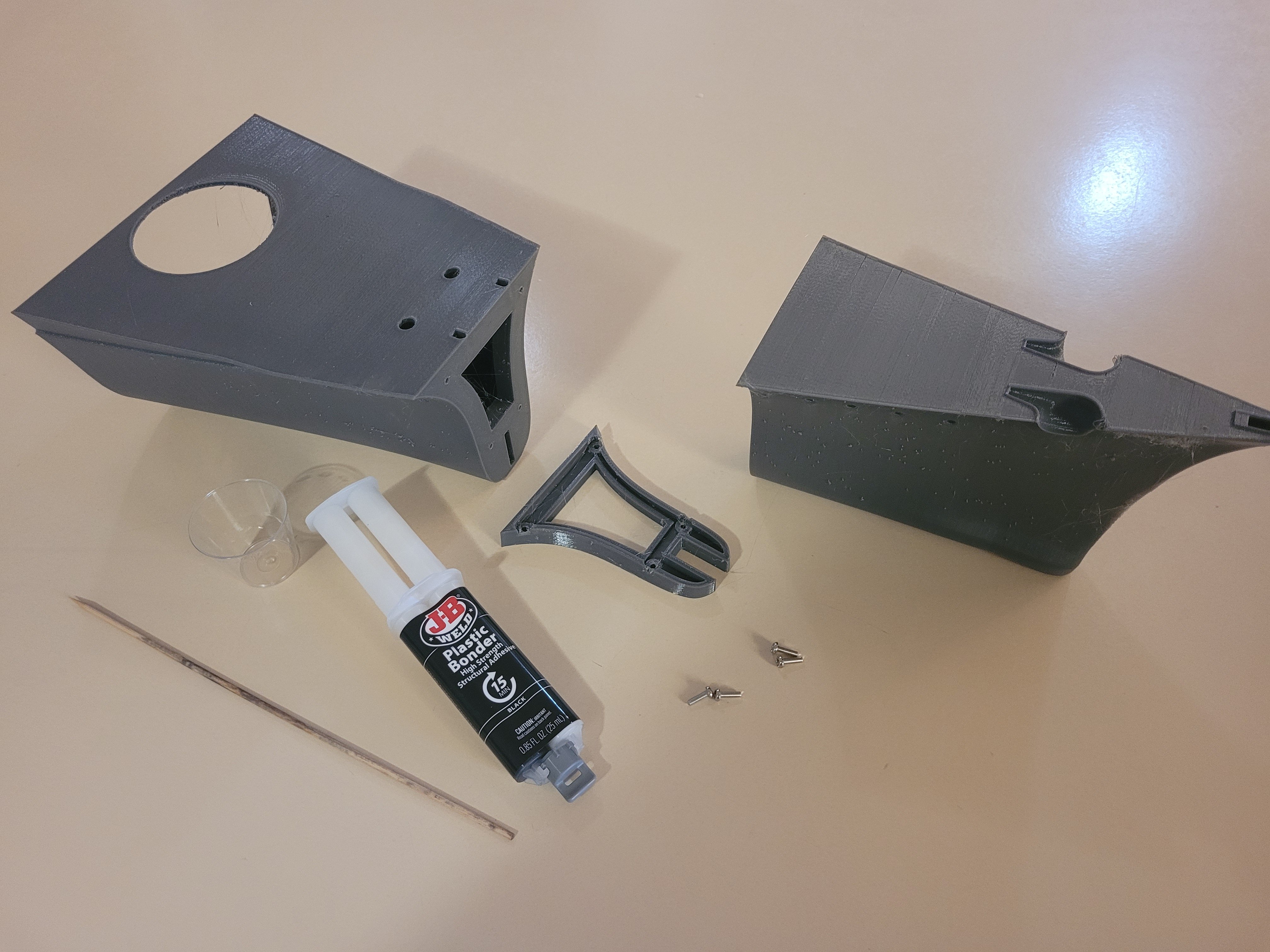
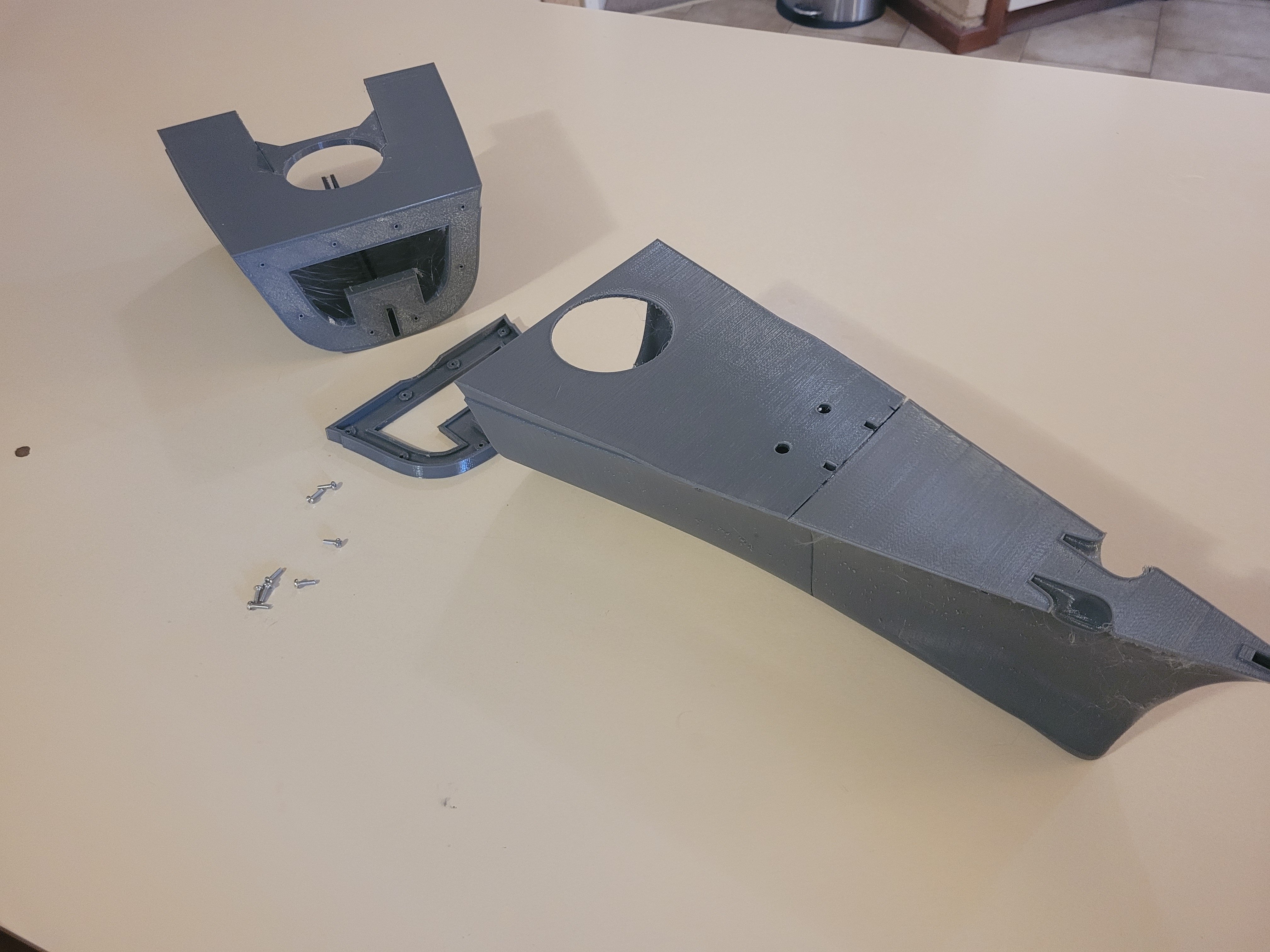
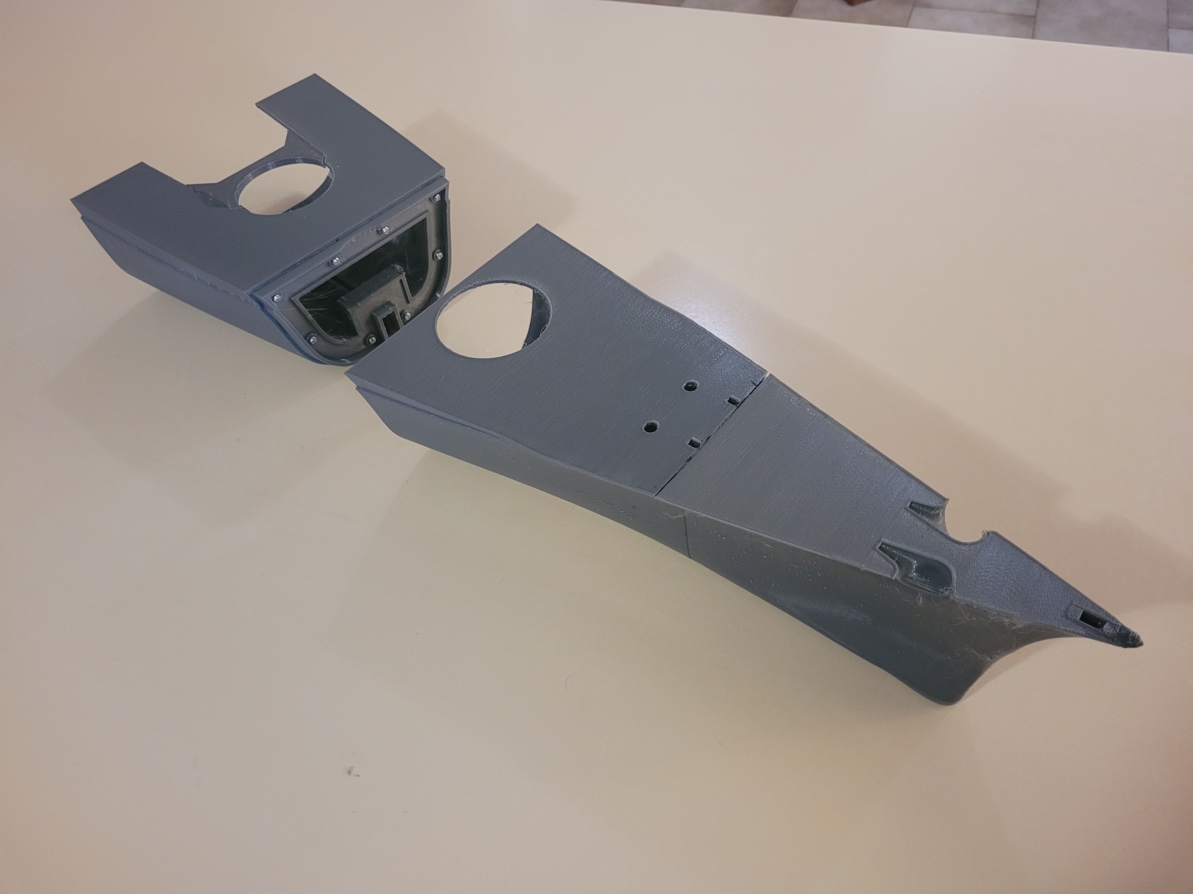
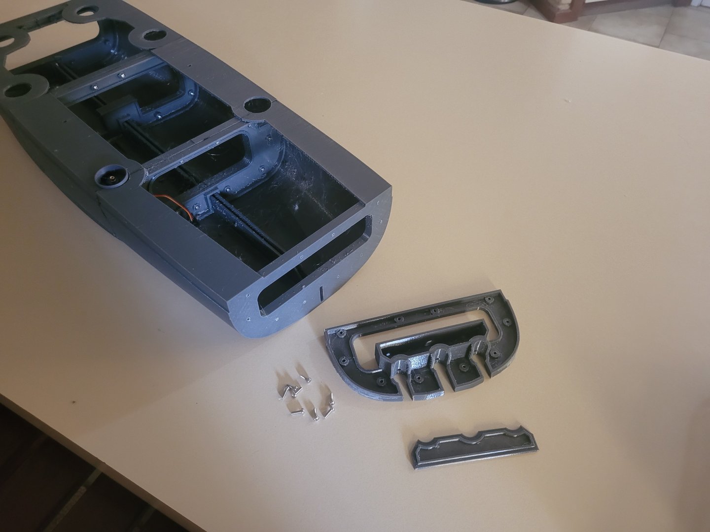
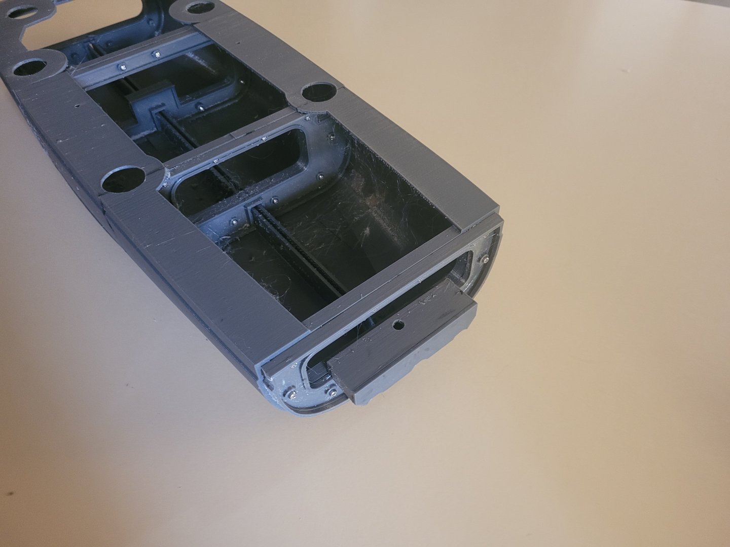
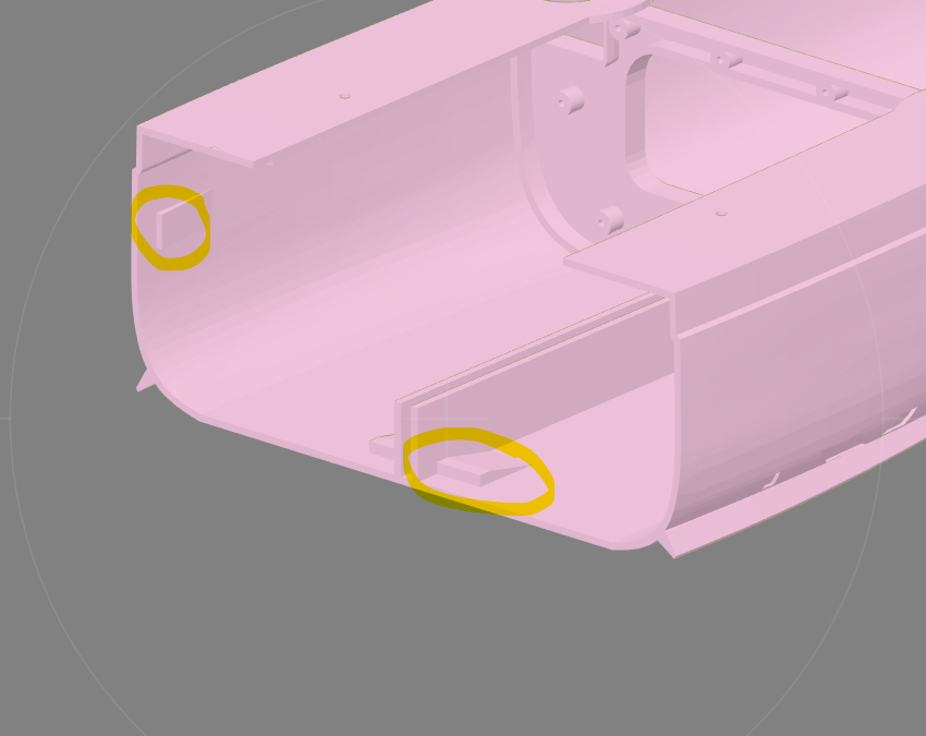
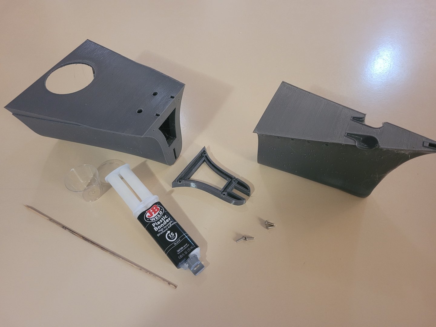
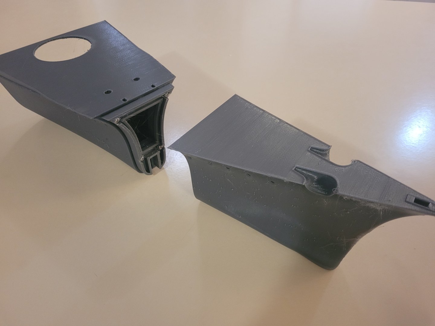
Hulls 4 and 5 are connected by a double sided joiner as the print direction on the hull pieces changes direction. The joiner is attached to Hull 5 with JB-Weld and aligned using the tabs printed into the hull piece.

-
The hull is printed in PETG, I used a layer height of 0.3mm with organic supports on hull 1 and 8. I don't recall using supports on any of the other sections. The hull pieces are printed from the bulkhead upwards so there is no issue with build plate adhesion even though some parts taper out from the first layer (Like Hull 2 in the picture below) Hulls 1 and 8 are printed from the open end so there is a risk of instability due to the small amount of bed contact. I did have an issue with Hull 1 lifting slightly, you can see the gap when it is glued to hull 2. This is easily filled and the deck will be laminated with a detailed deck plate so should not visible going forward. Mating hull parts have a joiner that is attached to the bulkhead on one of the parts using JB Weld and M3X10mm machine screws. This is then JB Welded to the other part Etc etc..


-
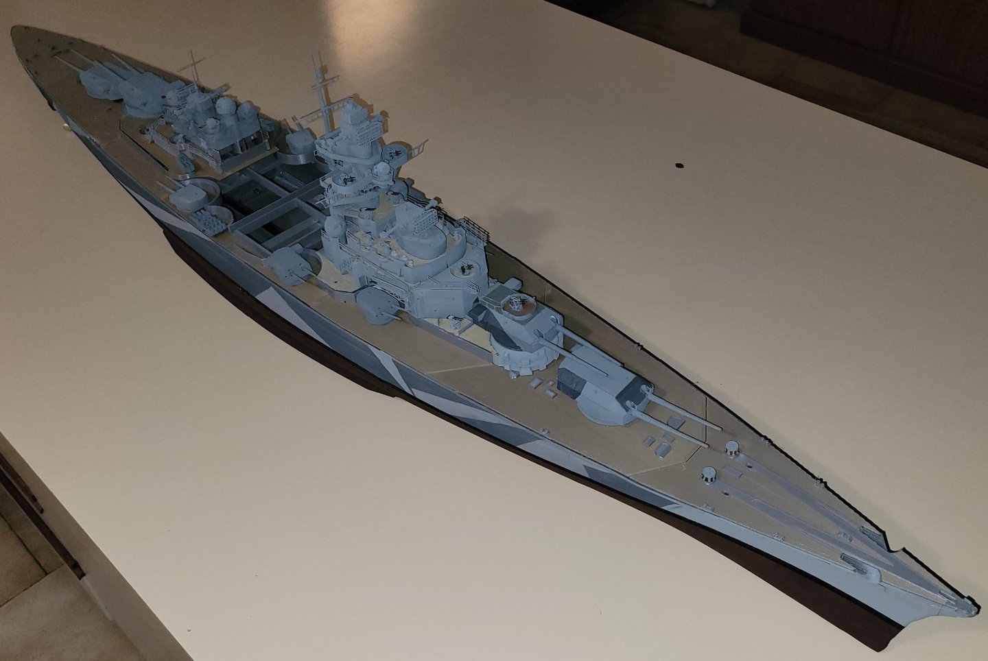
Hi, It's been a while but I have been doing stuff since completing the Tirpitz model. Bismarck and Tirpitz are brother ships (German navy ships are male whereas most other navies ships are female so grammatically not a sister ship). So making a 150 Scale model of Bismarck should be no harder than upscaling the Tirpitz Model 133% and modifying a few parts right??? Wrong This is a complete re-design correcting some minor issues in the hull and making it more friendly for remote control use. 1:150 versus 1:200 doesn't sound like much of a difference. My wife is quite displeased. Where are you going to keep that?
-
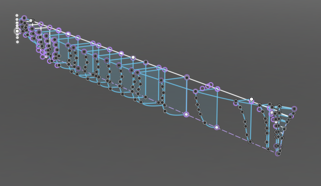
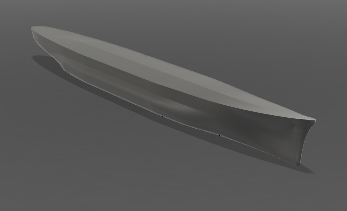
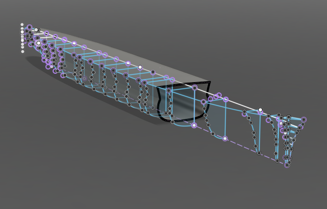
Hi, Whichever way works Having the hull line drawings is key. My preference is stem to stern lofting between the frames and using the hull lines as rails on the loft. The stem is a separate piece lofted from top to bottom. This creates a solid which can then be hollowed. The Tirpitz hull would simply not hollow so I resorted to modifying the frames to have an inner and outer profile and lofting the already hollowed hull. I would not recommend this method as it creates too many issues with mirrors and slicing later down the track. I'm doing a Prinz Eugen at the moment and am struggling with a lack of hull line details available. It appears a lot of the plans available are modellers interpretations of the hull outlines from 30 to 40 years ago. Prinz Eugen could not be hollowed from the last stern section forward (Fusion 360 had a hissy fit) so I sliced the model into 2 at origin and hollowed the 2 halves then joined them back together. So, this is the Prinz Eugen hull. It has largely been modelled from a reasonable plan and profile drawing and some very sketchy hull lines. You will note that there is not a ton of lines and to be honest, I could lose about half the centre frames without affecting the model. I prefer to let the lofting tools do the work and draw as little as possible but make sure that all the profiles connect correctly so the loft works better. So far I have about 20 hours invested in this, next we add the prop shafts, rudder, port holes etc then start work on the superstructure. Having said all that, I am not an expert by any means, more an interested amateur. So its basically whatever floats your boat Hope that helps some.
-
Still adding bits.... Just some railings and small deck accessories to go.

-
I didn't time them but it was not really appropriate. As I was designing the files virtually every one is print first one, test fit, check appearance, place in bin, adjust drawing and reprint. The parts were designed in 1/50 then rescaled to 1/200. The rescale has to then be adjusted to produce a printable part. Some detail is lost, other detail exaggerated to get it to print OK. When I am designing the files I tend to not have the luxury of being able to add lots of parts to the same print job, they tend to to be small jobs with one or 2 parts (remembering a lot of them go into the bin) Now that the parts are right, you can load the Resin printer with as many parts as can be fitted to the build plate as the print time is always the print time of the tallest part. That dramatically speeds things up a bit. Not so with the filament printer, extra parts means a longer print time. A straight up print with the current files would take around 2 weeks on 2 printers (One Filament, one Resin), around 1.5kg of filament and 2 kg of resin.
-
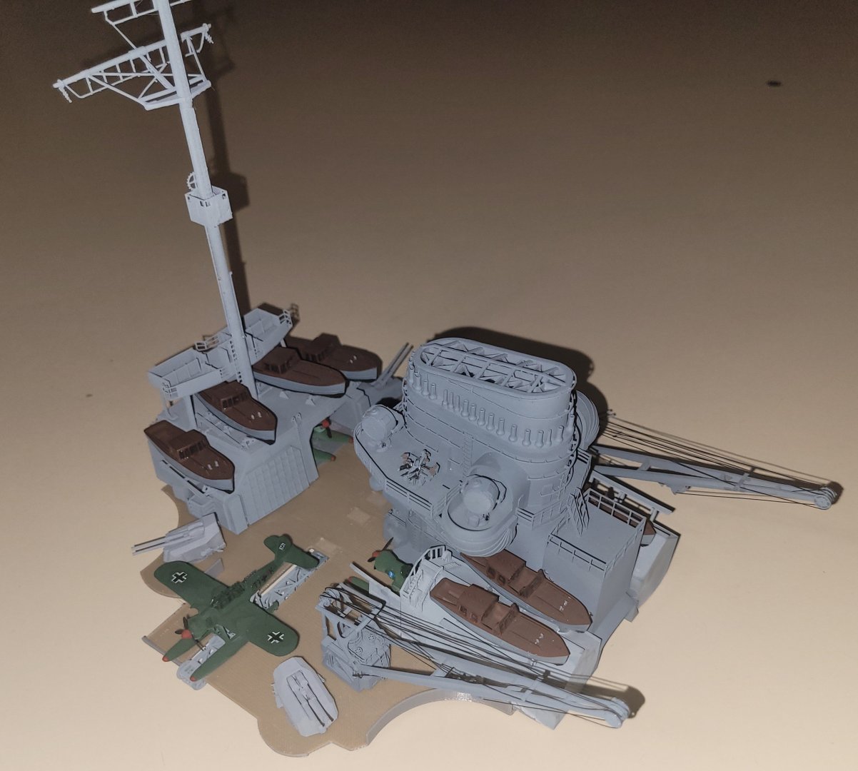
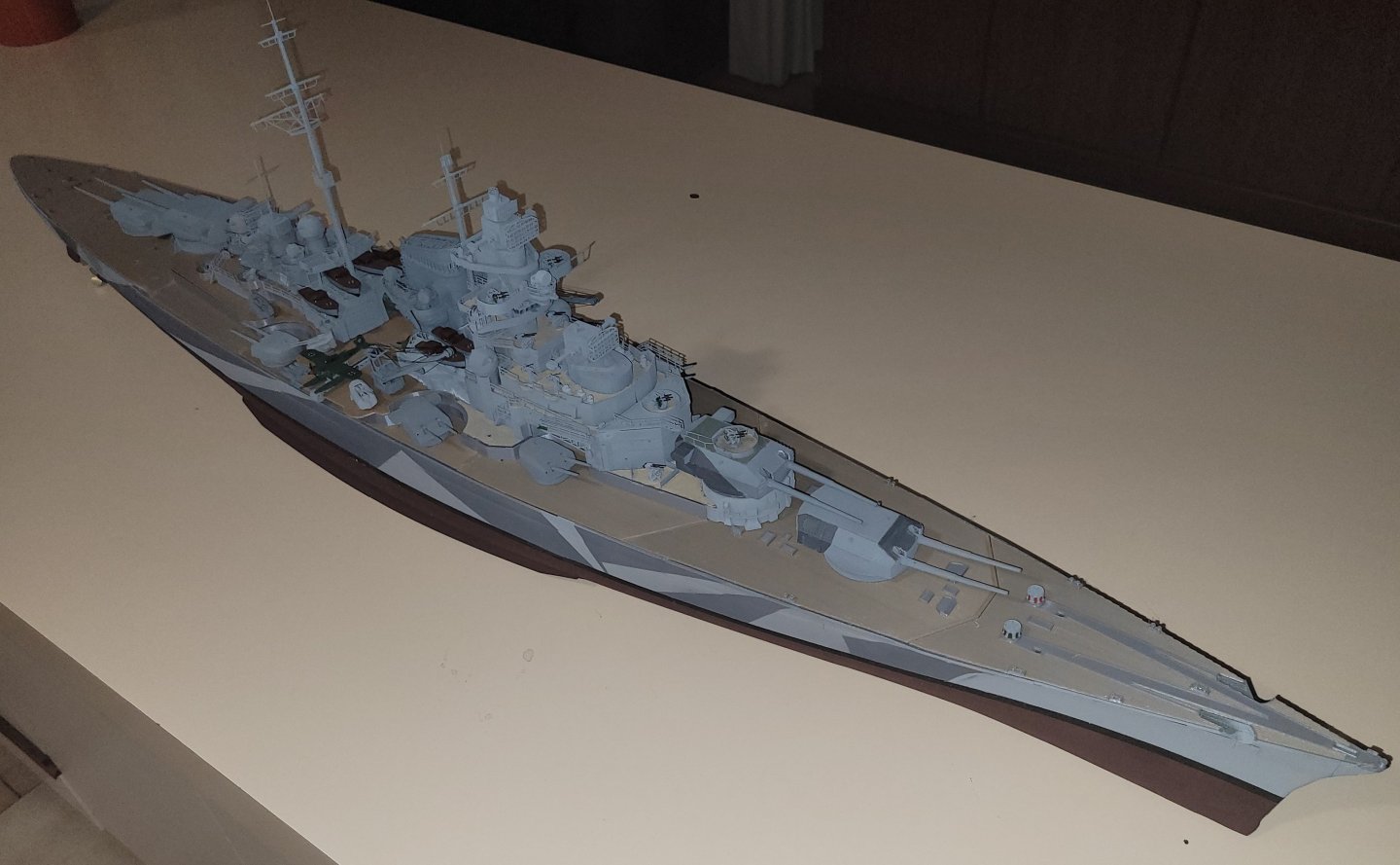
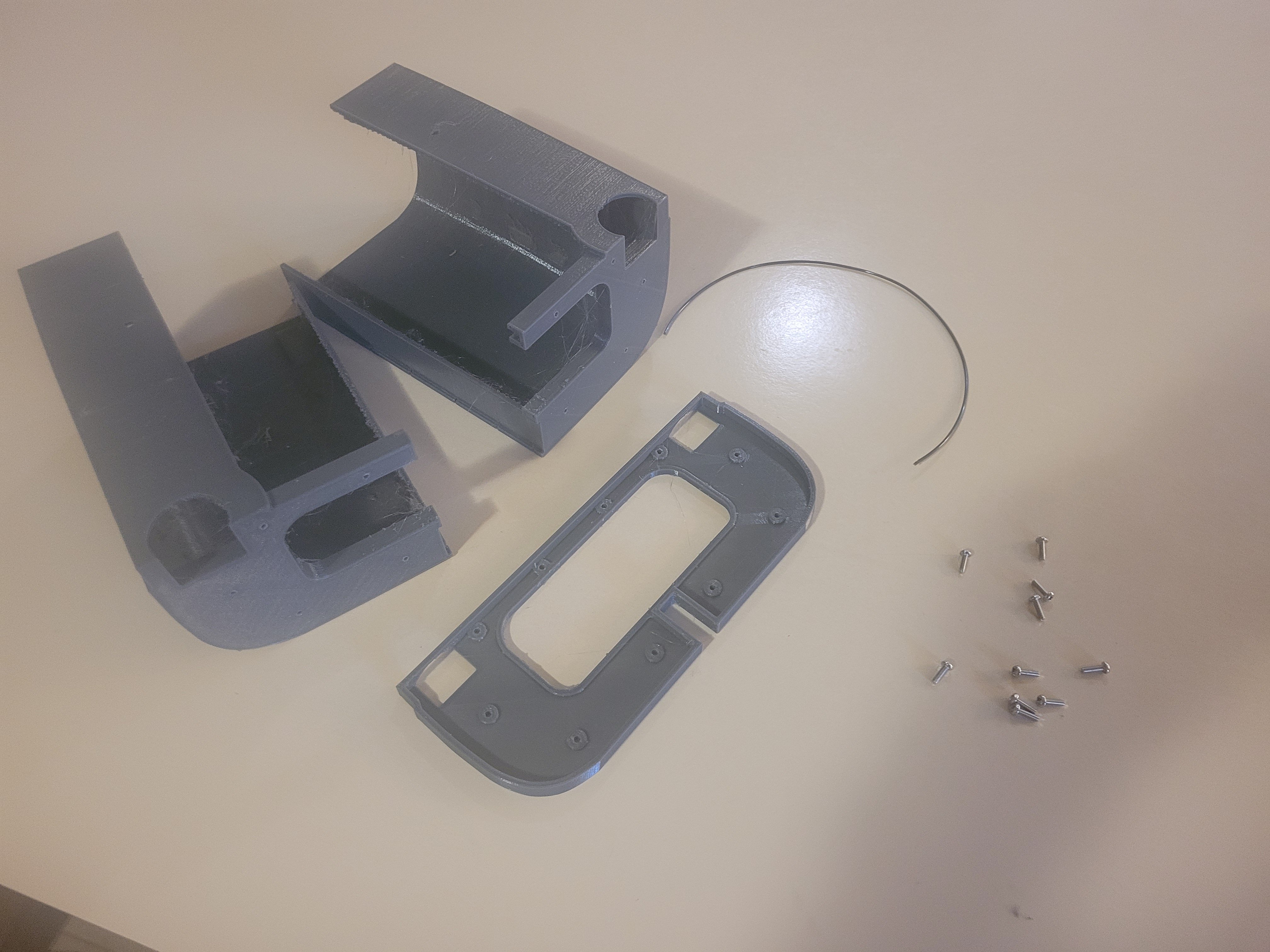
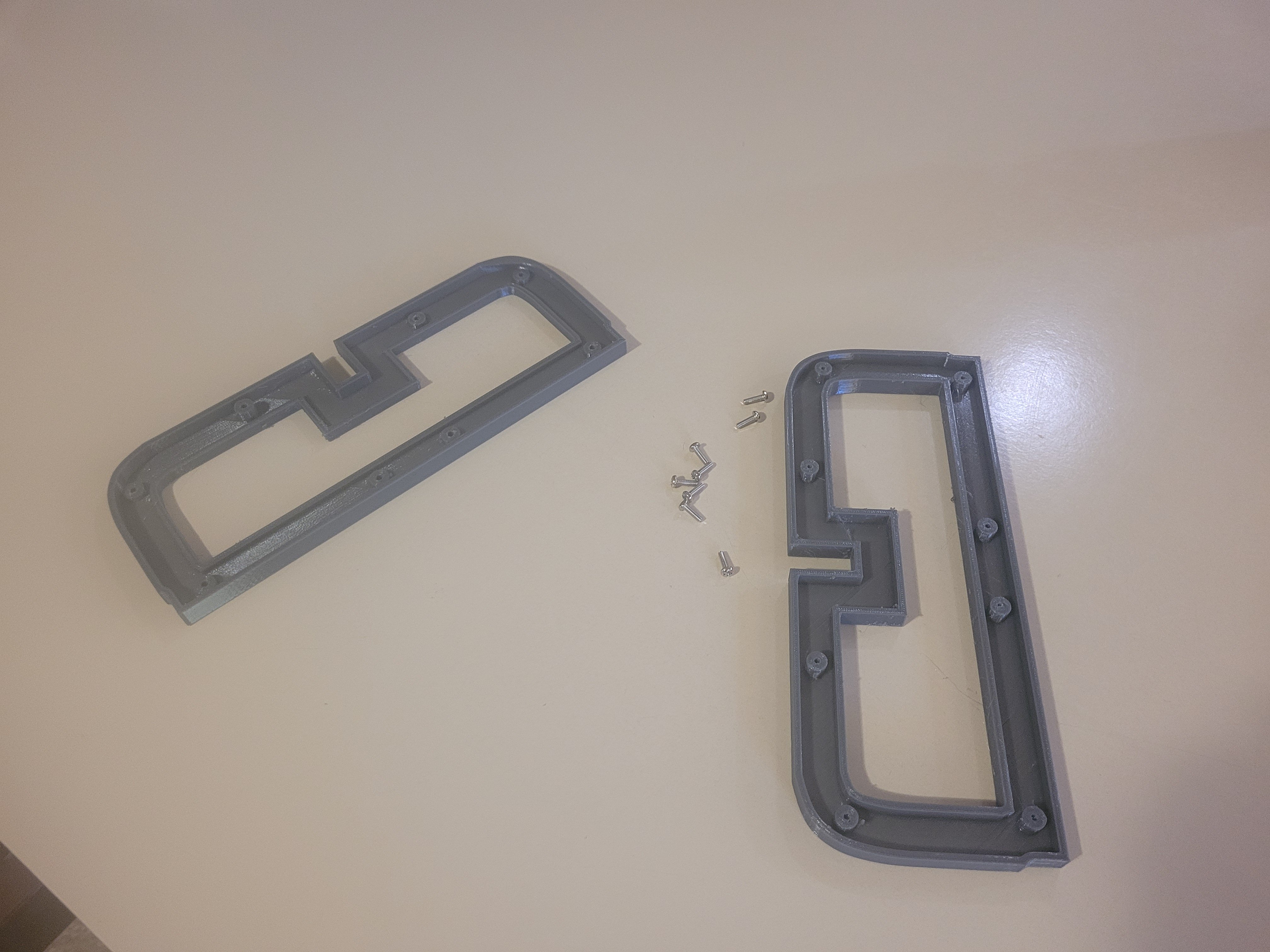
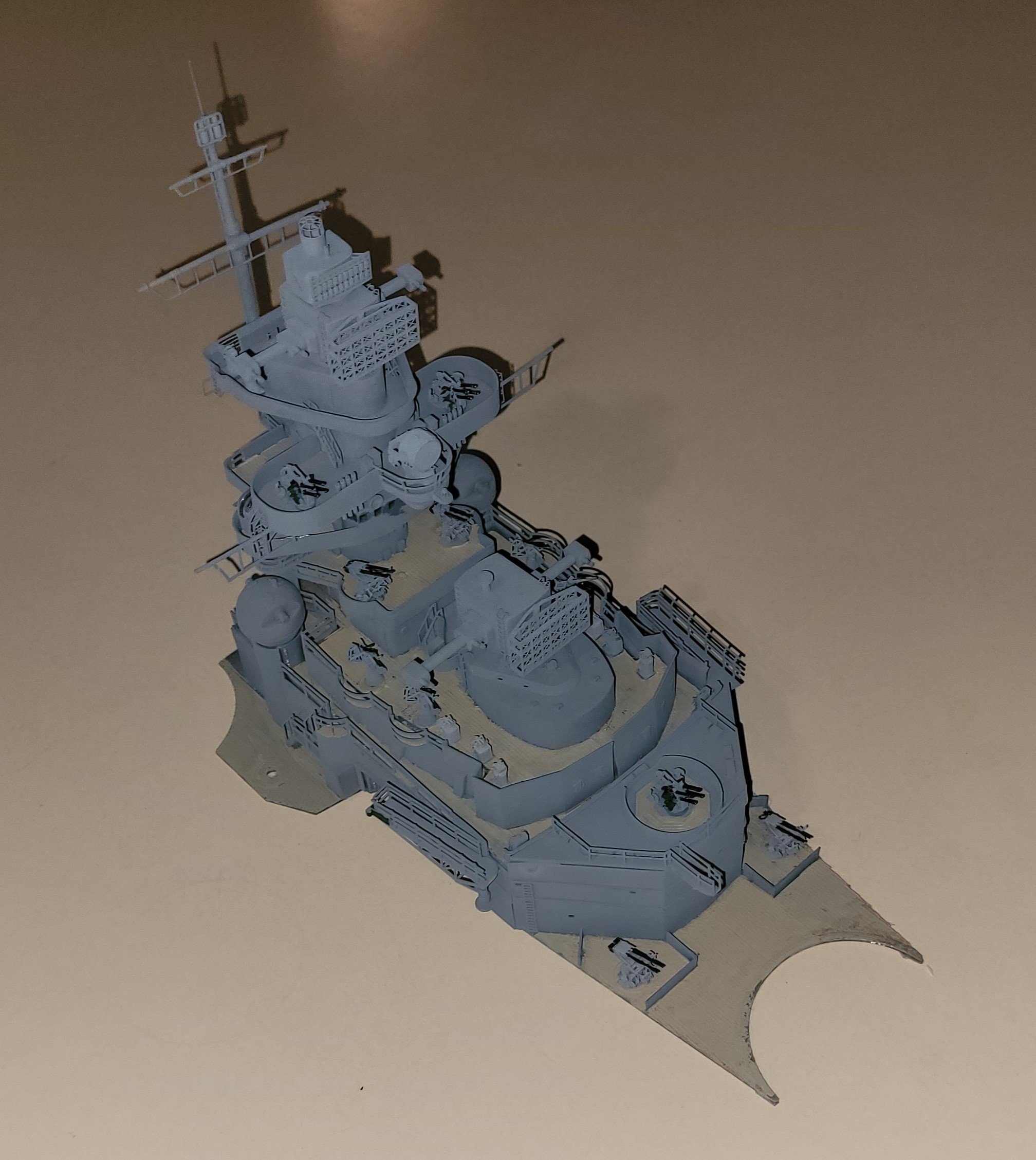
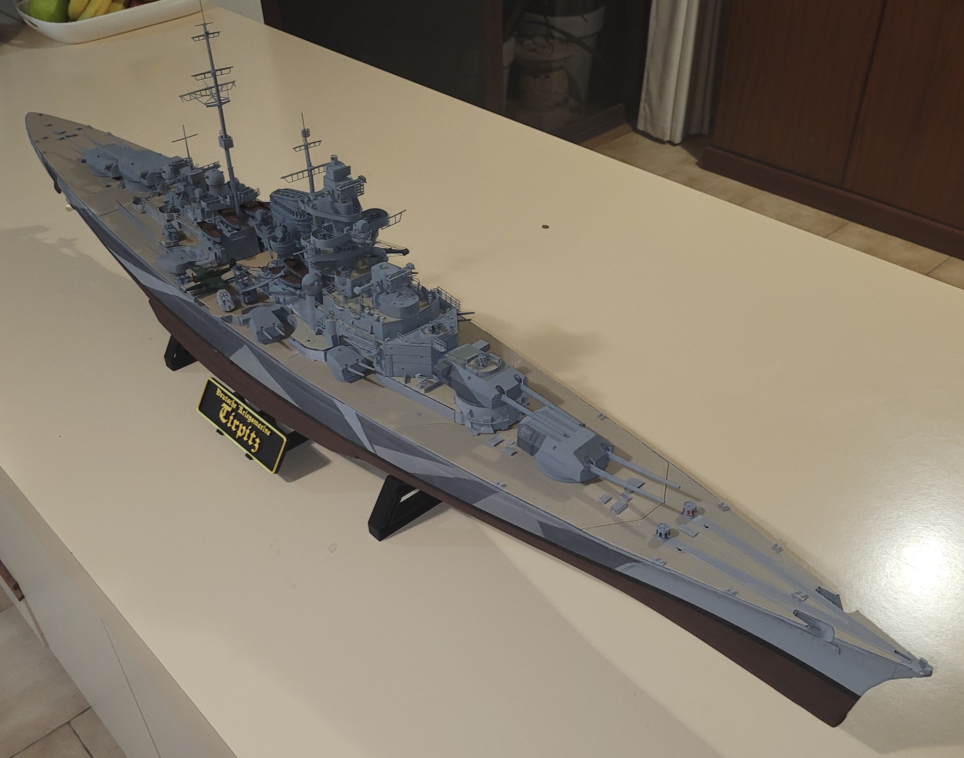
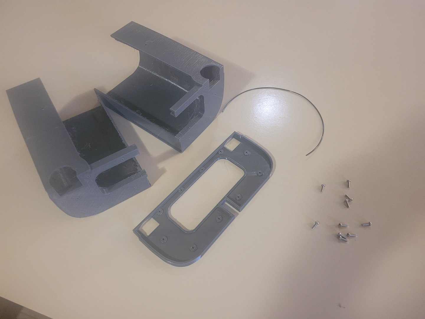
Next the forward superstructure. Assembly is quite similar to the rear control deck: Lastly is the hangar deck: Straight forward assembly: Then add it to the hull: Ready to go on its stand: Still a swarm of small parts and detail painting to go before its finished, but its a bit closer.