


flyer
-
Posts
1,004 -
Joined
-
Last visited
Content Type
Profiles
Forums
Gallery
Events
Posts posted by flyer
-
-
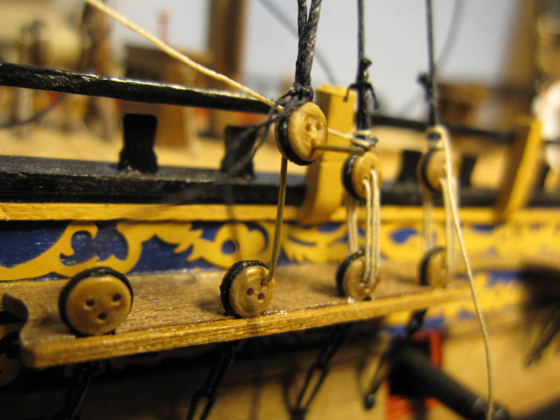
Next step was setting up the shrouds on the main mast. Despite the little tool the height of the deadeyes varied and I had to retie one per side to get an acceptable result. The main preventer stay was also put in place.
But when I wanted to set up the main stay I missed the heart blocks. I don’t know if I misplaced them or if they were missing altogether.
The captain was checking the alignment of the deadeyes – and not happy
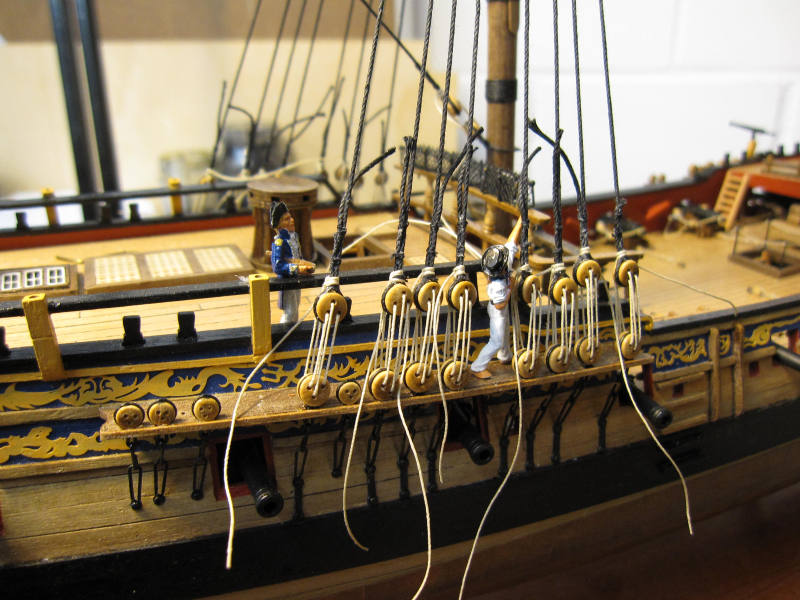
After resetting the third deadeye it looked a little better
-
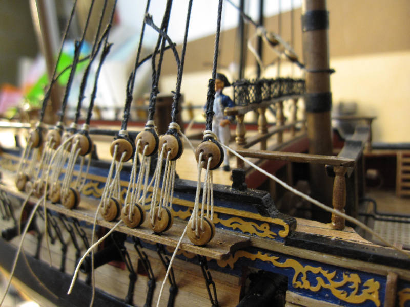
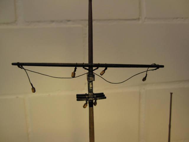
The rigging was started aft and low. First all the shrouds on the lower mizzen mast were prepared and the foremost pair was set up.
To get similar distances between the deadeyes a simple little tool is used: a wire bent into a Z.
After first 2 shrouds I installed the mizzen stay. Those 3 were set up and their pull balanced so as to leave the mast in its true position. Thereafter I continued pair by pair with the shrouds working aft. Each pair was set up to keep a constant tension on all the shrouds and the stay.
The stay got a simple mouse botched by a cross between a lopsided figure 8 and a stopper knot and was seized (wormed?) to below the mouse. Any kind of mouse I tried so far was somehow unsatisfactory. This was at least quickly and easily done.
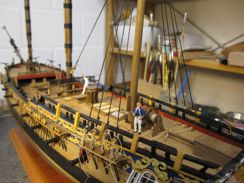
For the pictures I also played with some scale figures. I like it how they enliven the model.
The first two pairs of shrouds and the stay are set up
Stay and simple mouse
OK. I had some skilled help.
The little Z-wire-tool
Captain Jack was checking the progress
-
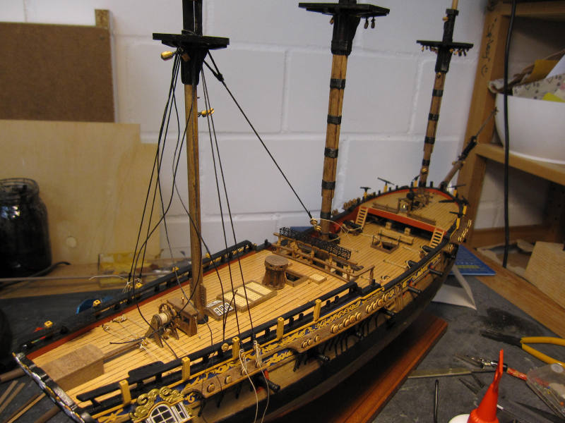
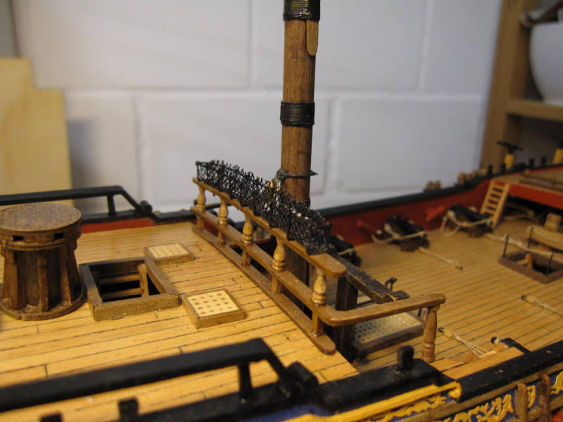
On my Pegasus I did a few minor works such as making the hammock netting on the quarterdeck rail and the handrail on companionway as well as touching up some parts with wood colored paint as suggested by Ron.
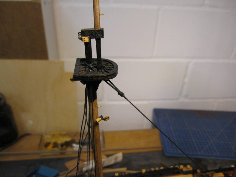
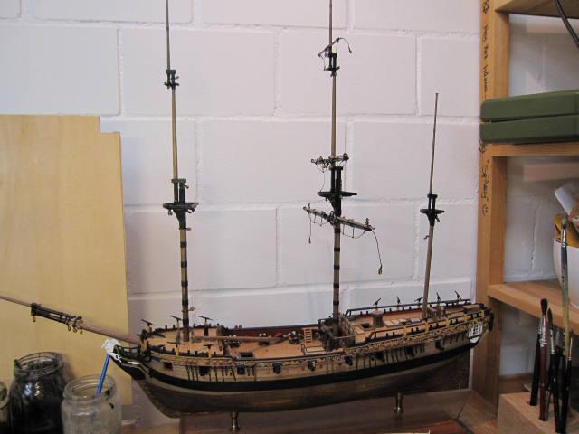
Next was a small step for a mast but a great step for all shipbuilders: the stepping of the masts. Fortunately they ended up more or less true and the first step of the standing rigging was also done: the gammoning of the bowsprit.
The edges of the hammock netting look a bit unkempt and will need a shave…
Companionway
The first step of the standing rigging. Quite a few more to follow…
-
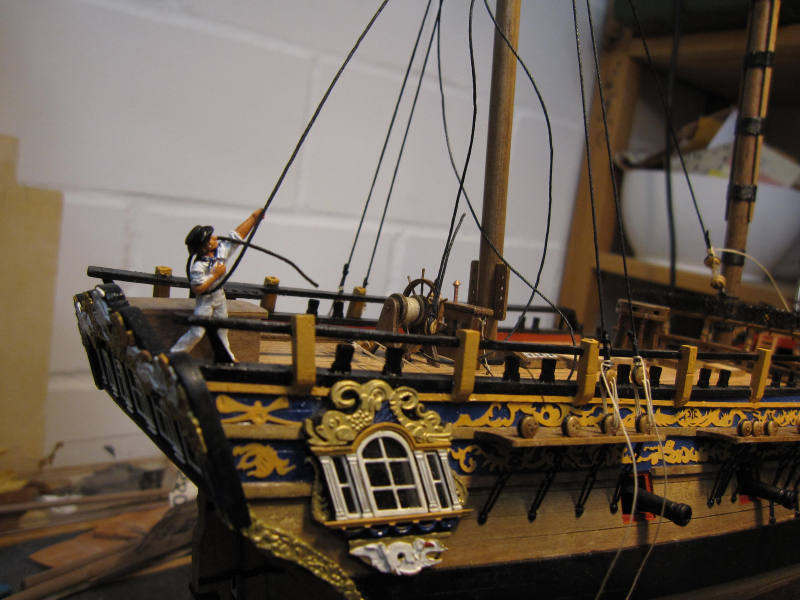
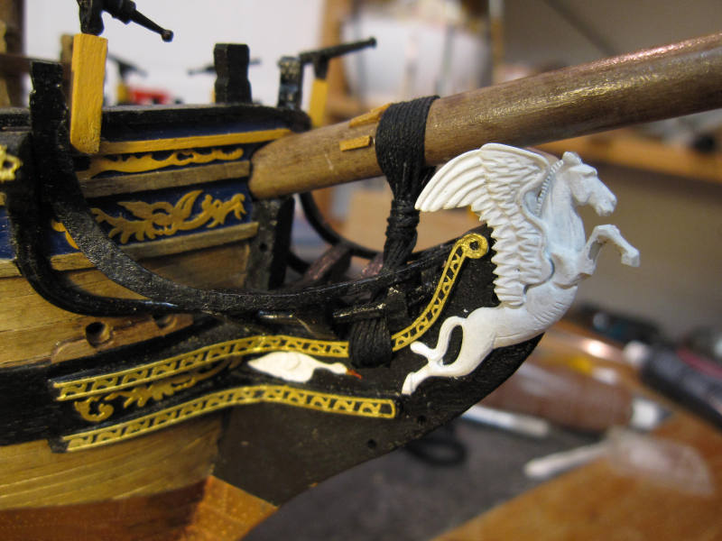
In between I tried to build a traveler for the bowsprit.
I intend to rig sails. Most probably they will be furled.
To rig the jib a jibstay must be rigged and its lower end will be fixed to a traveler. Of course I remembered this only after the blocks on the end of the jibboom were already in place and I had to fabricate the traveler around the boom.

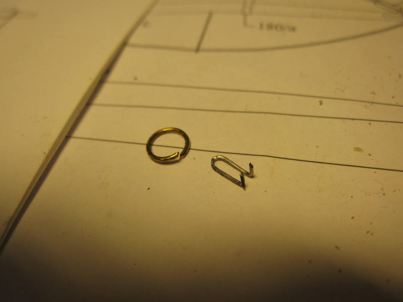
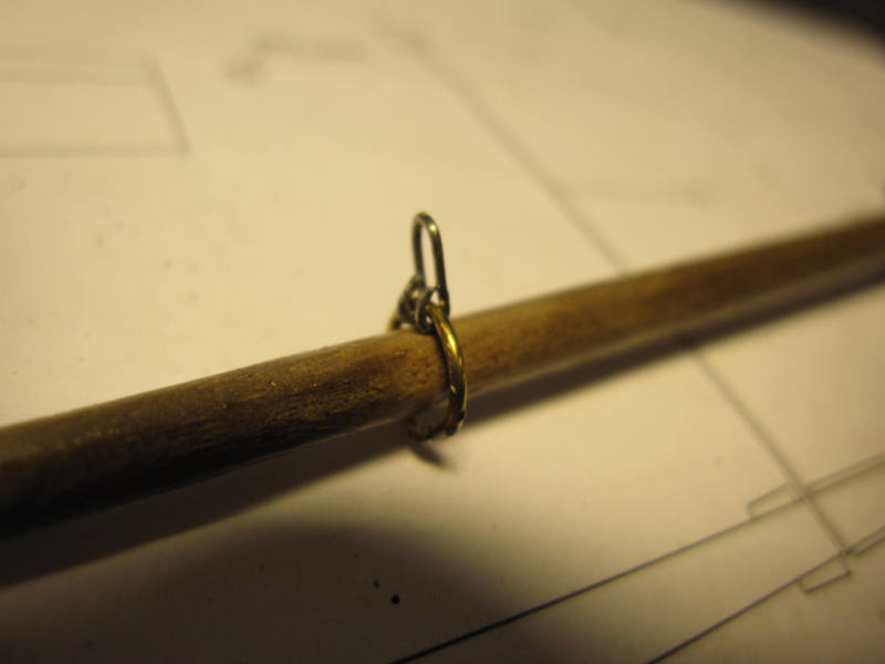
A ring made of 1mm brass wire and a thimble made of 0.4 mm wire were assembled and the ring was soldered. Then all was painted black and after cleaning the jibboom again I had an approximation of a traveler.
Open ring and thimble
Traveler on the boom in the raw…
…and painted
-
Thank you, Frank.
Whenever I almost succeed with such a tiny self-made piece I get a hint of the satisfaction those scratch builders must feel – but then I remember the frustrating, unusable tries lineing the road to success…
I will stay with kits!
Take care
Peter
-
(The edges of the plywood parts in the pictures above look partly ugly. Taking up a suggestion from somebody in MSW 1.0 I tried later to paint them in wood color. That’s something I will do in future builds before installing such parts.)
The last two yards to make were the spritsail and the sprit topsail yards. They were finished according to the dimensions in the plan. Now all the yards are completed and the next step will be the stepping of the masts and then the rigging will begin in earnest. After all that preparation work I’m actually looking forward to it.
Spritsail yard
Sprit topsail yard
-
Next in line was the fore topgallant yard. Here the dimensions in the plan are in agreement with what I found in James Lees’. It was a straightforward job.
In between yards I tackled another point on my to-improve-list:
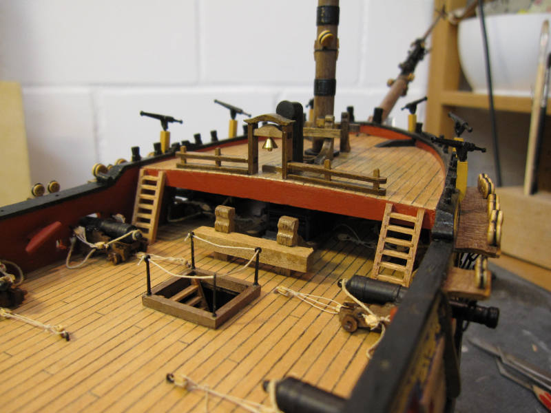
Unfortunately I did use those two ugly pillars on the side deck which were supplied with the kit much to my regret.
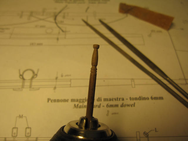
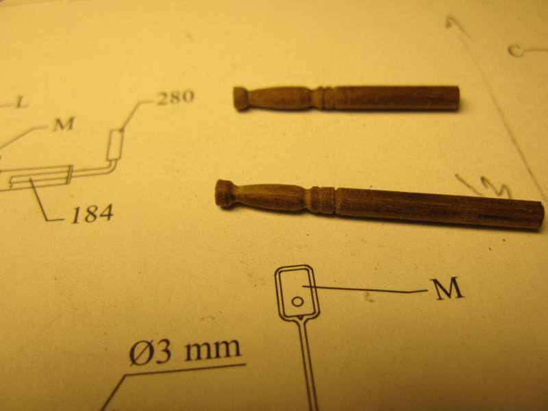
Finally I took some leftover 3mm dowel, put it in the drilling machine and scratched away with needle files and sandpaper. In three tries I got two nearly similar pillars with a height of 14mm.
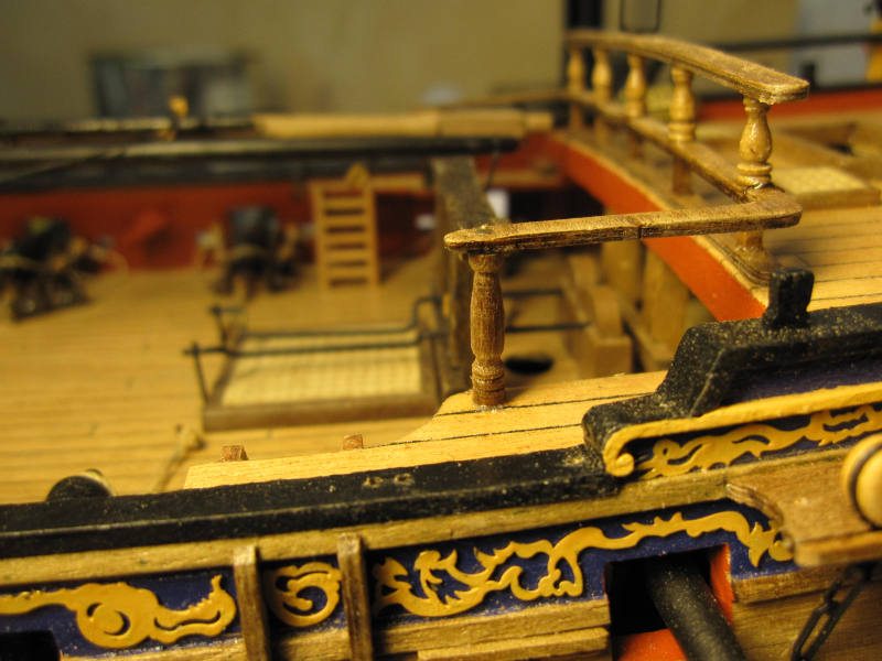
The old pillars were carefully cut out (they were – as the new ones are - fixed additionally with small nails in their upper and lower end) and substituted by the new ones.
It is definitively an improvement and I’m happy how relatively easy it was to fabricate those pillars with the simplest means.
Old pillar

Drilling machine replacing a lathe
New pillars not yet cut to length
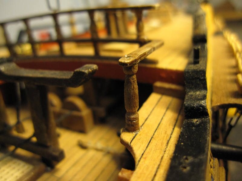
New pillar in place
I’ll have to scratch away the superfluous CA glue
-
Hi Frank
Thanks, I will.
 There could be worse things. Just imagine 5-masted ships could have been the standard of the sailing ships area!
Take care
Peter
-
Hi B.E.
Thank you for the very interesting and extensive answer.
As I understand JoTiKa says that they are using plans of a (Bermuda build) schooner which seems to be very similar to what is known about Pickle. So, they regarded it as kind of a sister ship and did stick strictly to those plans. Unfortunately no reproduction of those plans is easily available (it seems somebody wants eventually publish a book about that subject). So this model certainly is NOT Pickle but perhaps a sister. In my opinion this should be made clearer by JoTiKa and the model should be renamed.
The Boats were apparently just taken out of what was available from Caldercraft. By the way – I like what you did with those boats. Unfortunately they don’t sell any 16’ boats – only 18’ and 14’.
I still fancy that kit for a project between bigger ones and as one which could be built with full sails. In any case my boat(s) would be positioned in a traditional way and the actual rake of the fore mast would be decided while building.
Also the dimensions are modest enough to smuggle the finished model into some nice spot, e.g. on your desk, where it would hardly be noted by the admiralty.
Cheers
Peter
-
Hi Frank
I hope you can bear another voice in great-work-chorus. Here it is: Great work!
Another idea how to display the ship: why not high and dry on an (uncharted!) sandbank waiting for the next flood? This has happend to the best of the skippers – even Jack Aubrey was one of them. The crew could scrape at the barnacles or prepare the ship to refloat it.
Cheers
Peter
-
Hi blue
(I hope you don’t mind the familiarity, calling you by your first name, but I couldn’t resist when I read about your interest in fermented grapes and blue or ‘blau’ means rather well oiled in German!)

Thank you for the compliments.
Yes, despite all the shortcomings, it is a splendid kit. Only with Caldercrafts Granado I had an even better one. But manufacturers must make money and therefore I guess a shortcut is unavoidable now and then. I’m just glad that we have at least 2 companies which offer kits on a level unknown until a few years ago.
Cheers
Peter
-
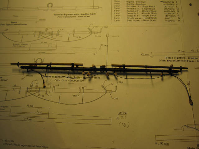
Back in the model yard the fore topsail yard was taken in hand. It was done in a similar way to the fore yard with the maximum thickness of the octagonal section reduced from 6 to 4 mm. Thus the 6 mm dowel could be used.
Fortunately this was the last of the rather complicated yards with stun sail booms. Now only 3 rather simple yards remain to be made. Then the masts will be stepped and the rigging work will start in earnest. I find I am actually looking forward to making the ratlines after all that preparation work.
Stun sail booms lashed
The finished yard

-
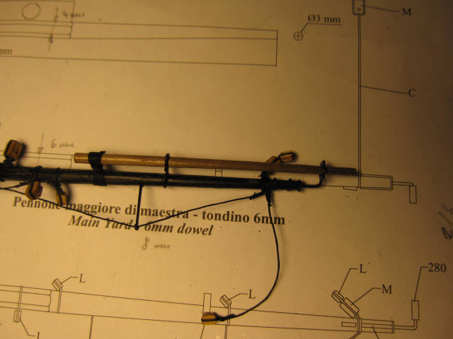
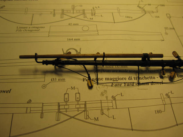
Next came the fore yard.
The work was similar to the main yard. The maximum diameter across the octagonal section was reduced to 4,8mm.
The stunsail booms inner rings had to be reduced in diameter again (cut open with a cutting wheel, adjust the remaining length, bend it do a smaller ring and fix with CA).
While working on the rings I found that the rings on the main yard are the wrong way. There is a thickening in the boom ring which represents a roll for easier movement of the boom. It should of course be on the lower side of the ring. I don’t know yet if correction is possible.
To fix the stunsail booms I put on a lashing with 7 turns, similar to what is used to fix the bowsprit. First step is to fix the line with a timber hitch on the yard. Then the 7 turns are laid, crossing the existing turns each time when going through the gap between yard and boom.
-
Thank you Mobbsie
…although – isn’t there some horse in it?
Cheers
Peter
-
Hi B.E.
Congratulations on a superb build! Outstanding! I love your boxwood coloring.
Before starting my current build I was considering Pickle but I really disliked some details. You did away some of my concerns (transom, size of the boats) but others are remaining.
I don’t believe that a boat really was stowed off centerline thus creating not only a miss trim by its weight but also by the possibility for the wind to get some hold on it. And in addition some gun ports are blocked too. You could balance the weight by putting more guns on the opposite side but you still would have to rearrange your armament every time you use the boat. So why not ask for smaller boats which could be stowed between the masts?
Probably you know that contemporary picture of Pickle, where the fore mast seems straight rectangular to the deck while the main mast keeps its aft fall.
The Royal Naval Museum model of Pickle has its fore mast set more forward (with aft fall).
Both variations are moving the balance point of the sail area more forward than on Caldercrafts Pickle which means its fore mast position seems at least questionable.
I put those questions forward to Caldercraft. The answer was that they couldn’t change the original plans and left the question open why on that contemporary picture pickle looks different.
What do you think?
Cheers
Peter
-
...and the curator together with his director, would like to put their hands on it, but shall do so after entry to the afterlife.
Hi Paul
Do not temp them too much, please!

Great work(again).
Peter
-
The crossjack yard was again reduced in diameter to a maximum of 4mm across the octagonal section. So I could use the 6mm dowel.
The diameter of the mizzen topsail yard was reduced to 3mm, making it rather similar to the main topgallant yard.
Checking those lighter yards provisionally mounted on the masts I find the overall picture quite convincing.
Crossjack yard finished
Provisionally mounted

-
The main topgallant yard was made according the plans. Fast work for once.
-
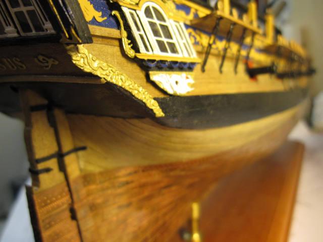
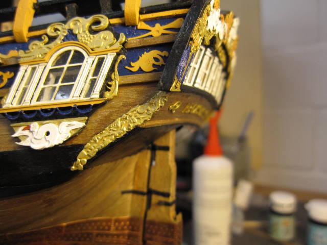
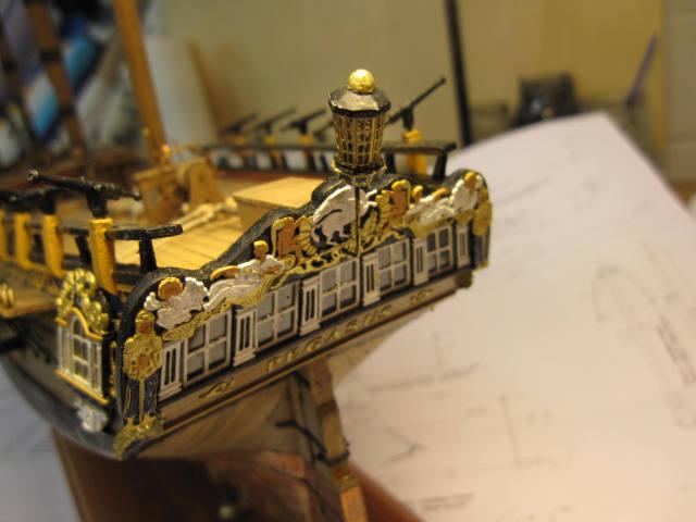
The correction of the lower counter’s sides was next.
When first attaching the ornamental piece, I had problems to place it. A main reason could be the straight instead of concave lower counter. (That’s another one of those mistakes which I found out too late to correct it.)
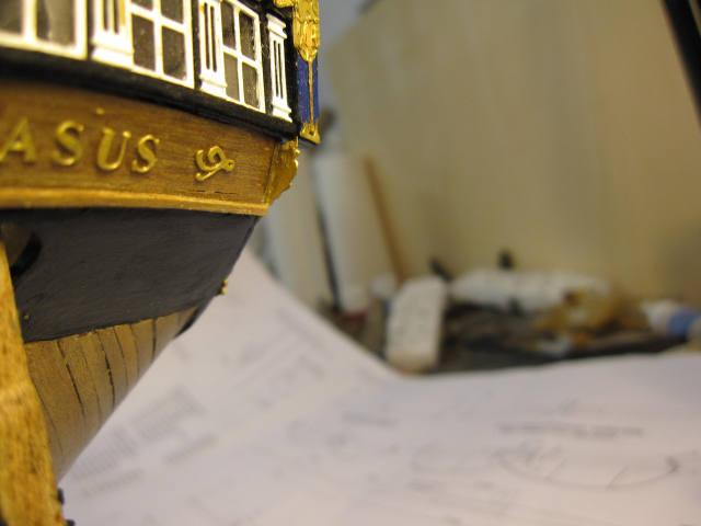
First I peeled the offending pieces carefully off. Then I started to cut away with a small cutting wheel following the ornamental lines. The part above the main wale was doubled up with some spare deck planks. After some gilding with paint it could be reinstalled. Voila! It does look better.
Old look...
...with the ornamental piece heavily overhanging the counter.
Doubling up the peeled off piece
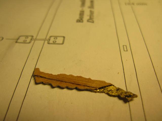
The new look
- Kathy Teel and Mirabell61
-
 2
2
-
Hi Aldo
Well I try to be not to hard on me. Thanks anyway.
But looking at what our fellow model ship enthusiasts demonstrate in this forum I sometimes wish I could take everybody’s best tricks…
Do you have a picture of the actual installation of the lantern on HMS Atalanta?
Cheers
Peter
-
Hi Paul
I still marvel what you did and can do with simple cardboard and a knife!
This could be a kind of lightweight construction. Any idea how much your elegant monster weights (or shouldn’t I ask about the weight of a lady?) and how long is she again?
Cheers
Peter
-
A rather easy improvement was the addition of a ships lantern. While browsing trough caldercraft’s fittings I found that the tops lantern should fit Pegasus as a single transom lantern.
For obvious reasons it was only provisionally installed.
Assembled lantern (needs some repainting)
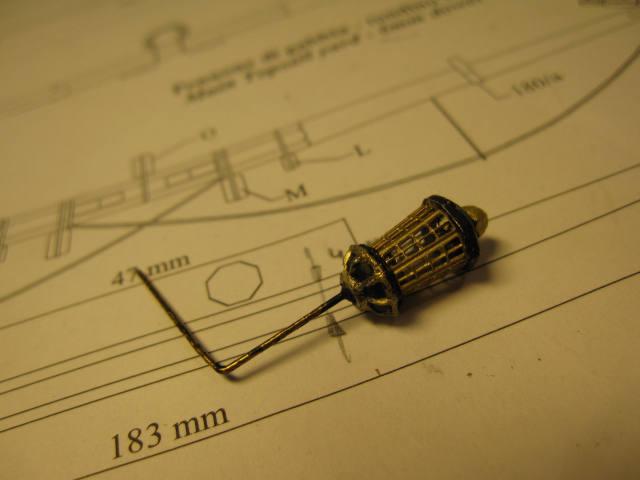
Provisionally installed. I guess it will need two additional diagonal struts for the final installation.
-
All the time, while I was building the yards I kept looking at the Pegasus and was comparing her with other build logs.
Several points were either differing with other models or with contemporary pictures in the web and either they were nagging me or had to be explained:
I know, that the colouring of the ship was probably different (e.g. more red on the deck fittings etc.) but as all you probably have are snapshots or descriptions of one particular point in time. I guess the skipper had usually to take what colour was available or could buy and paint more according to his liking. I always liked the Bellona’s colour scheme on the coppered model and decided to follow it.
In other logs the side badges were heavily improved to get a proper 3 dimensional look. To correct them I would have to build them anew. Probably too much and I will learn to live with my simplified badges as intended by the kit manufacturer.
Gunport lids will be fixed on the first two and the aftermost 3 ports. This again is not in agreement with some sources but as I try to be a considerate skipper I will pay for the additional lids out of my own pocket.
What would be the use of the installation of bulwarks, if you are unable to close the gunports within those compartments?A ship of this size would probably have a lantern. I found one which should suit Pegasus.
That ornamented side piece left and right of the lower counter is overhanging and doesn’t follow properly the contour of the hull. This should be corrected.
Stupid me did use the ugly pillars supplied with the kit for the rail along the short gangway or side deck. They will be replaced!
That has to be corrected!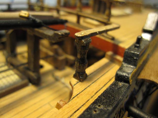
-
Hi Aldo
Thank you. Yes I think those Granado’s look OK but I would still like to have lighter finer seams. On Granado I was using full scale sail sizes and I will try to reduce those to reduce the still rather large bulge on the yards.
Take care
Peter
HMS Pegasus by flyer - FINISHED - Victory Models
in - Kit build logs for subjects built from 1751 - 1800
Posted
While waiting for the heart blocks some other tasks could be taken in hand:
There will be some spare spars over the waist (where the boats will be stowed onto). After searching in a few clever books I decided to make 4 spare parts:
1 jib boom
1 main topmast
1 fore yard
1 main topsail yard
The jib boom could be made from leftover 4mm dowel. The first attempt was according the plan and just a little to short to rest safely on the bearings. I made it again a little longer. For the other parts I will have to wait again for some ordered walnut strips.
Spare jib boom in its position (below lies the prepared collar for the main stay)