


flyer
-
Posts
1,004 -
Joined
-
Last visited
Content Type
Profiles
Forums
Gallery
Events
Posts posted by flyer
-
-
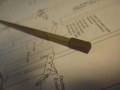
The driver boom is finished. I changed dimensions to the values above and did ad two cleats holding those two double blocks 1/3 from the scarf. And again some cartridge paper ‘iron’ hoops are holding the scarf together.
‘iron’ hoops holding the scarf and boom together
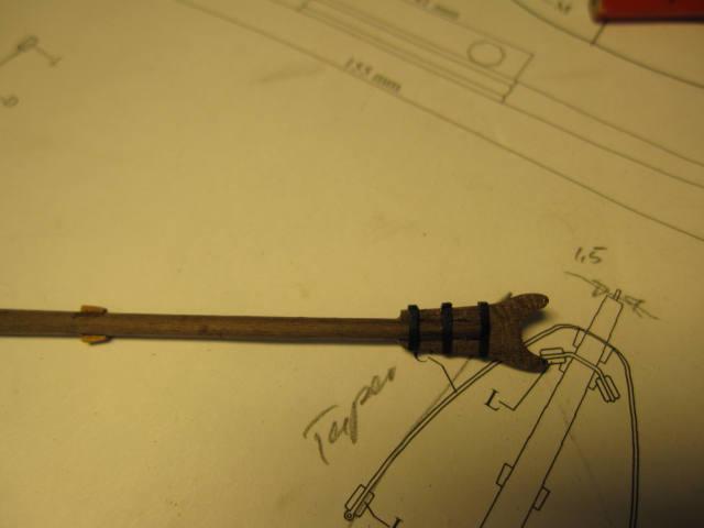
Gaff and boom finished
-
Hi vths(?),
hi RayYes, I think mast building is a lot easier if you have such a plane. And that hint about the fastened drill and the sand paper on a piece of wood seems a very good one. Thank you.
Thank you, Ray. I do my best and to cut and reshape the boom rings (after some hesitating) worked ok.
Cheers
Peter
-
That’s a very nice ship you are building there! I especially like an realistic captain’s cabin and yours is looking good.
The caulking looks good as well – something to try on my next one. Up to now I used to color the edges of the planks with a black marker which gives an acceptable result after sanding the deck.
Cheers
Peter
-
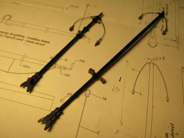
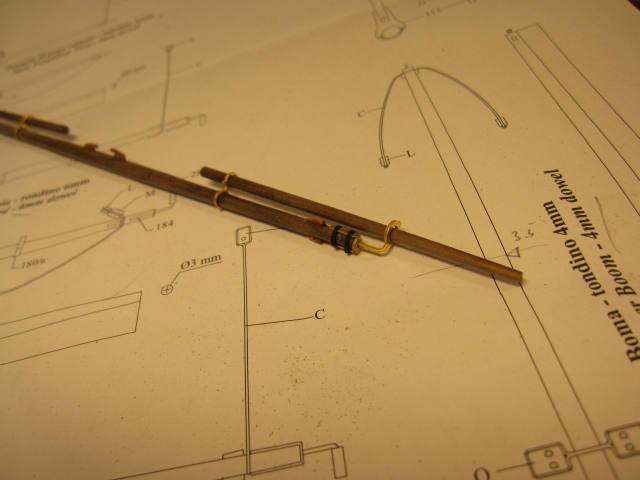
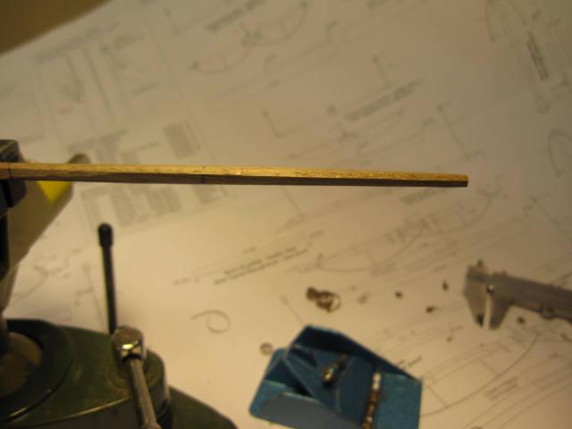
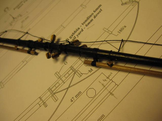
Next the stunsail booms were made. Again some dimensions were missing in the plans but good old James Lees came to the rescue. The outer 2/3 of the boom was tapered from 3 to 2 mm.
Then the mast fittings were added with the same modifications as on the main yard. The Yard was then painted, the blocks added and the booms lashed.
Booms and fittings added
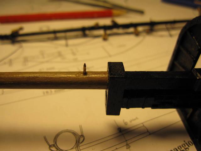
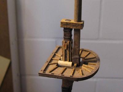
Last point was a little trick I don’t remember where I did pick it up.
To fix the yard position at the mast, the tip of a nail was glued at the right position into the mast and a corresponding hole drilled into the yard. This loose connection is – of course – not according to the prototype but completely invisible and a nice help when installing the yards definitely.
Nail tip at the yard position in the mast
Yards provisionally placed at the mast
Only ten more to go.... and yes I’m glad they didn’t build many 5-masted ships.
-
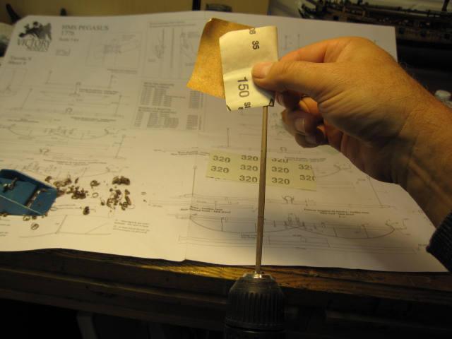
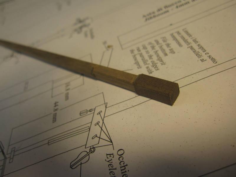
The Yard is then put into a hand drilling machine and the free end is sanded round with increasingly fine sanding paper.
With the left hand I hold the machine and control the rpm’s and with the right I hold the sanding paper and control pressure and sand from tip towards the octagonal section.
The finished end is protected with masking tape when put into the holder of the drilling machine.
The yard is certainly not perfect but small flaws will be covered by paint, the fittings and the rigging.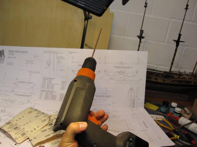

-
Now I turn the piece by 45° and plane down half of the wood over 4mm.
Then an 180° turn and the opposite side is worked down to 4mm. This is repeated until I have a rough octagon of 4mm diameter.
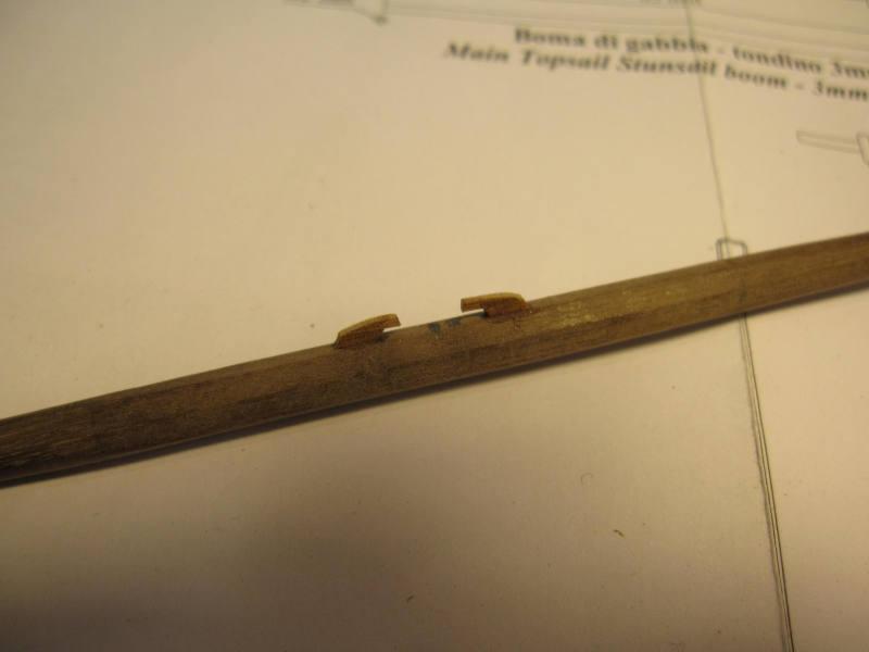
Then the parallel middle part between the slings is marked and both ends outside of the marks are in the same working order tapered down to 3mm at the ends.
Irregularities can be smoothened with the next step.
after the first 45° turn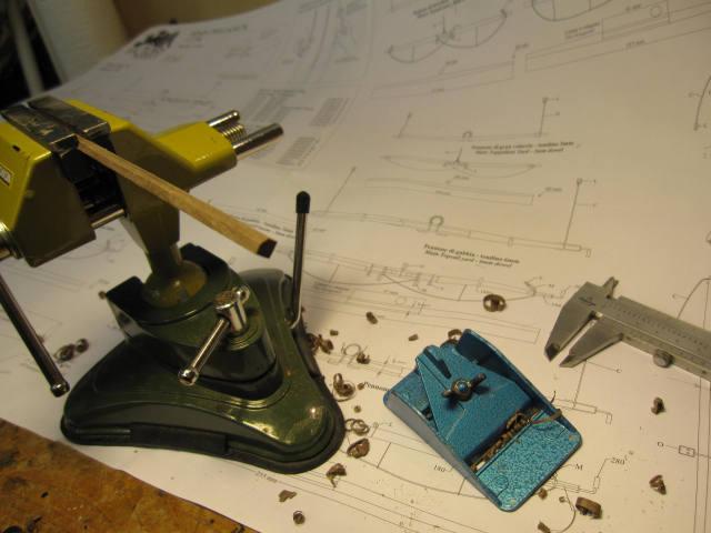
tapering started
-
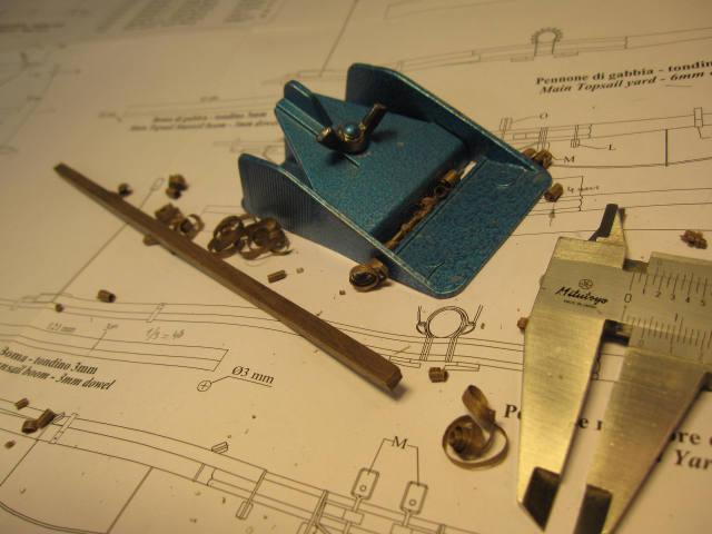
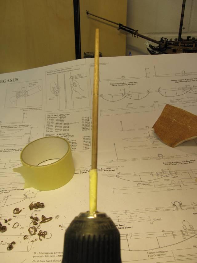
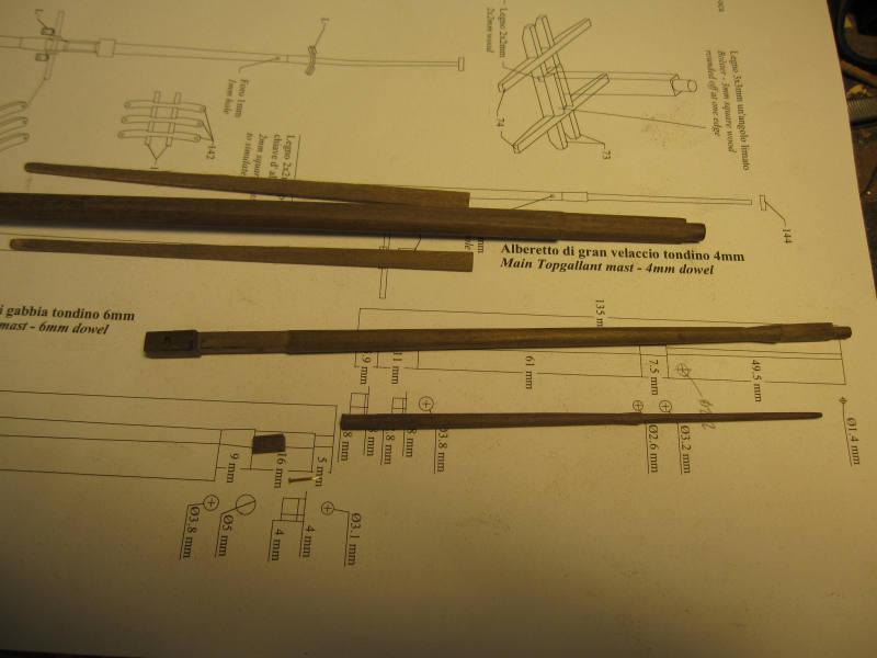
With the next one, the main topsail yard, I try to show in detail how I work the yards and masts without a lathe.
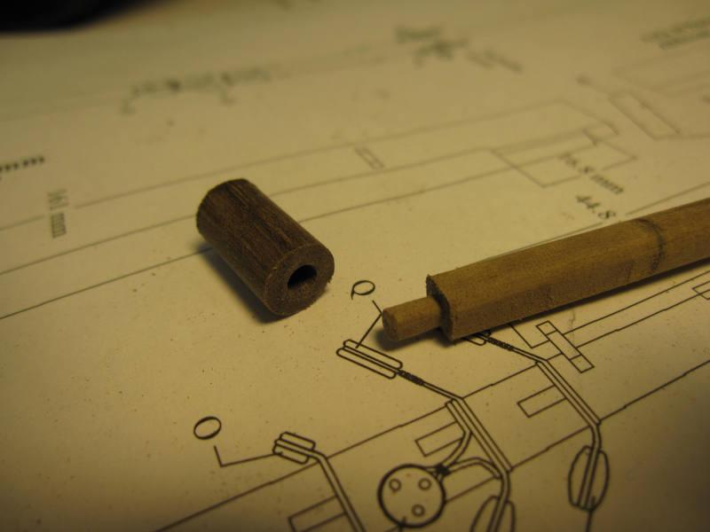
For the 4mm diameter between the slings the provided 6 mm dowel is fine.
The dowel is cut to length with a bit extra so that a clean end can be made.
Then it’s put into the vice and one side is planed (or filed) down to 5mm. Then it’s turned by 90° and the next side comes down to 5mm.
The next turn by 90° follows and now I work down to 4mm.
One more turn and some work and I end up with a 4mm square stick (square would anyway be the better starting point for most of the yards and the upper masts).working after the first 90° turn
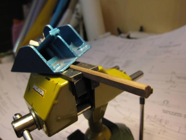
square stick finished
-
Hi Frank
Finally I found on my computer what I was looking for – an article about furled sails. I think it was copied from MSW 1.0.
Just food for thought…
Take care
Peter
-
The next step is the making of the yards.
A task I don’t really like because the rigging of the yards and booms is tedious to me - especially when you have done the first 4 and still about 8 to go.
The Yards according to the plans looked partly to be on the heavy side. Therefore I checked the relative yard dimensions with James Lees’ help.
A few diameters had to be changed to a smaller size. This is a great help as I can now use the dowels according plan and still file a octagon where necessary.
Only for the main yard I had to take a leftover 8mm dowel as the 6mm octagon in the centre is correct in size. The Fore yard will measure 5mm in the centre and the main topsail yard, the crossjack yard and the fore topsail yard only 4 instead of 6mm. The mizzen topsail yard will have a diameter of 3mm.
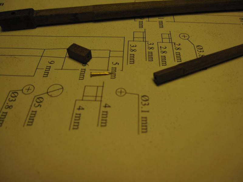
The diameters for driver gaff and boom will be 3.1 resp. 3.5 mm.
The first one was to be the main yard – in itself quite a project.
The dowel was first filed octagonal and tapered, then filed round where necessary again with the help of my drilling machine.
The boom brackets’ legs had to be shortened to fit according to plan.
The stunsail inner rings were too large to fit the yard. I cut them open, took out a bit and glued them with CA to the yard.The inner end of the stunsail booms are lashed to the yard.
First cleats added
Fittings added.
Painted, blocks added and booms lashed
OK one down, only eleven to go.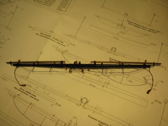
-
While checking the different books for information about lashing the jibboom I found that I made a mistake about the front end of the boom.
It’s cross-section shouldn’t resemble a square but an U.
The two lower edges were filed round and repainted.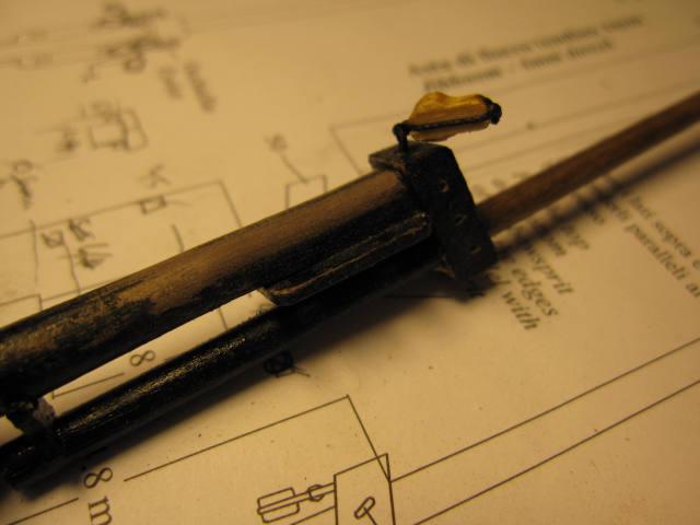
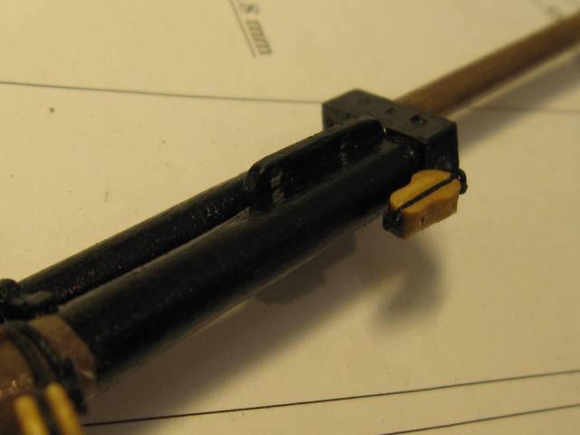
(During the first edition of that log some members supplied information about a possible lashing of the jibboom. As a consequence I put on such a lashing.)
Then I added a lashing for the jibboom and the blocks.
- Kathy Teel and Mirabell61
-
 2
2
-
Hi Mobbsie
I’m very glad, my friend, that you managed the tricky navigation trough the web and are again amongst us, fresher and newer than before.
Keep up the good work on Agamemnon. This is a ship I would like to build as well.
Cheers
Peter
-
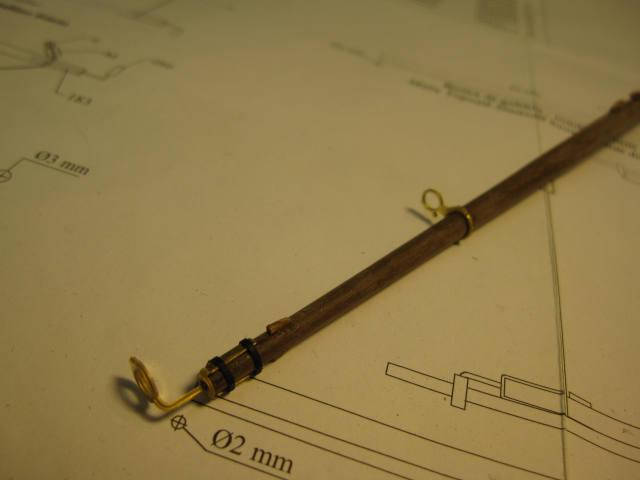
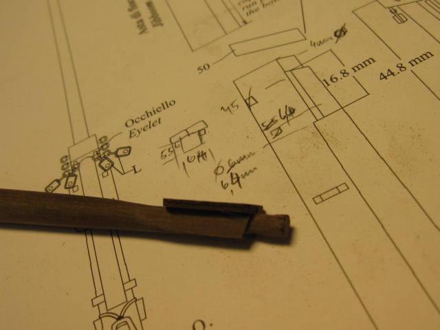
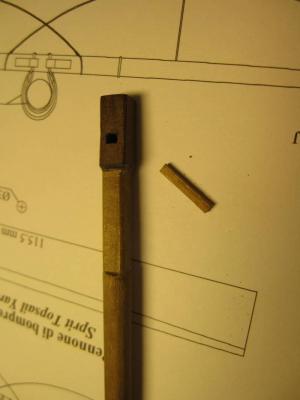
The making of the bowsprit was a bit a puzzle because dimensions were missing and the drawing isn’t clear. With James Lees’ help I tried a solution as shown below.
The missing dimensions for the jibboom were taken out of the drawings with a little help from James Lees again.
First a square end and a tendon were filed.
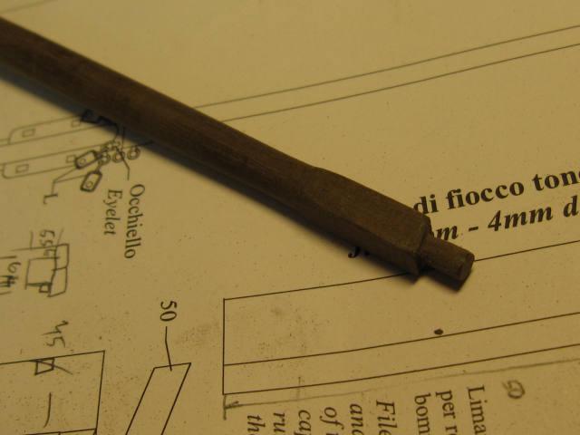
Then one side was filed down to the level of the tenon.
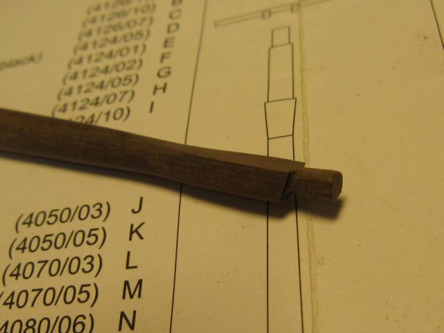
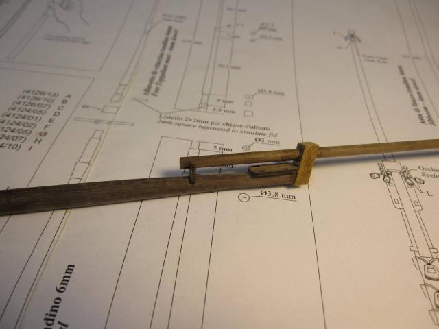
Bees added
I keep asking myself, if on smaller ships as this one the jibboom really wasn’t fixed with a lashing (none is shown in the drawings).
Was it then only held in place by the friction in the cap and the pressure onto the end resulting from the pull of the stay?
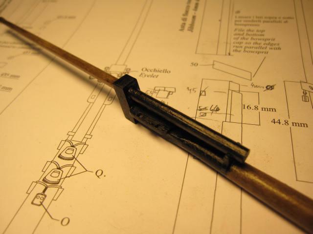
Jibboom fixed...
...and painted.
-
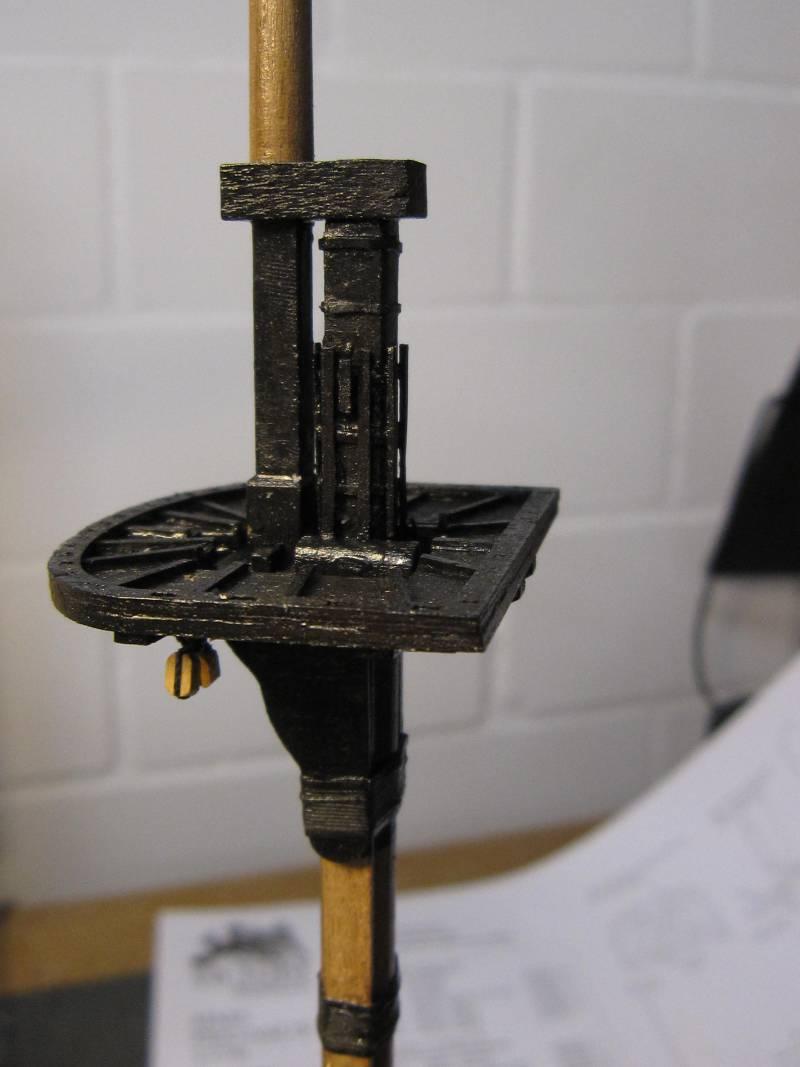
Topgallant mast added
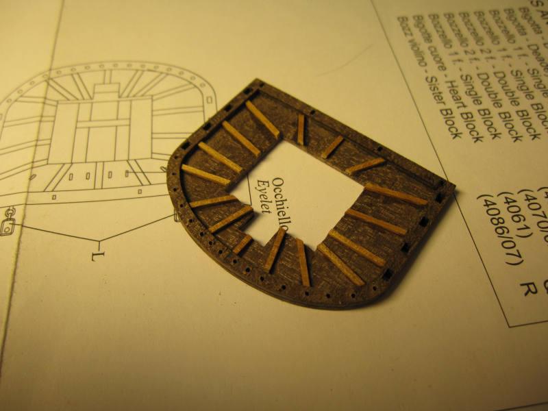
The deadeye for the mizzen stay is fixed a bit higher up than on the plan to let the stay clear
the quarterdeck rail and the hammock cranes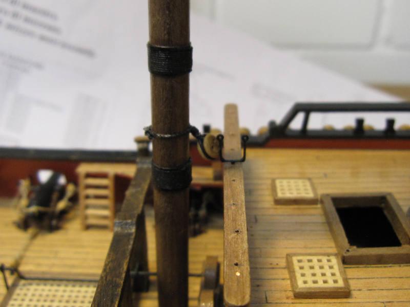
-
Hi Paul
It’s good to have you and your monstrous yet elegant beauty back online!
Keep up the terrific work.
Cheers
Peter
-
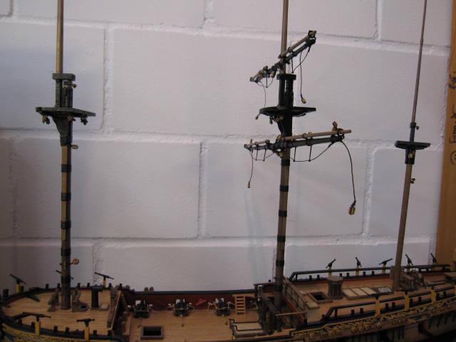
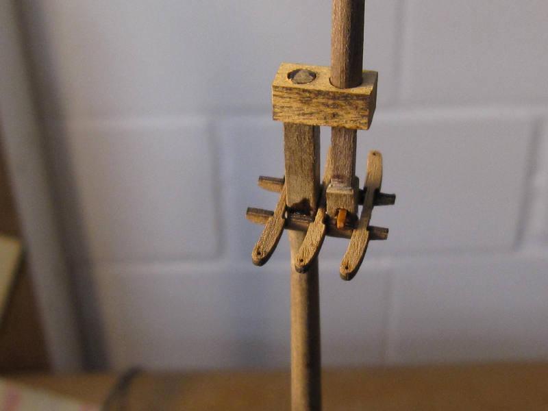
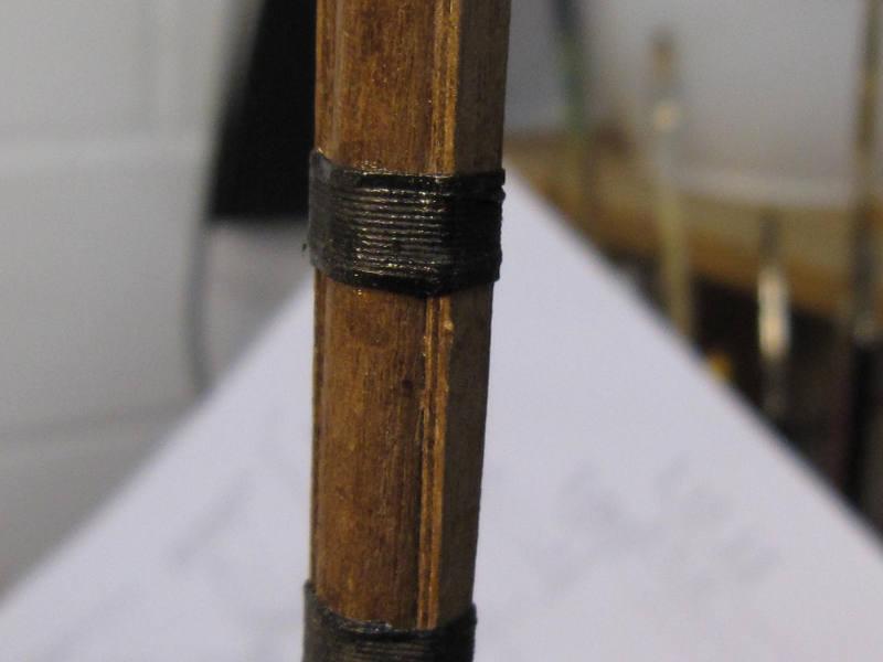
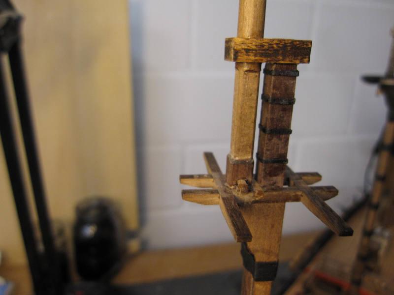
On Pegasus’ mainmast and foremast I added mast bandings made of paper and battens made of leftover deck planks.
Foot of a topmast
The mainmast is taking shape

The wooldings are protected with simulated wooden hoops made of paper.
mast bandings made of cartridge paper
The battens added


A finished masttop.
This and other details are added according the descriptions in James Lees ‘The Masting and Rigging of English Ships of War’.
This book costs a bit of money but it is an absolute gem and a great help if your building and rigging manual doesn’t show enough details.
-
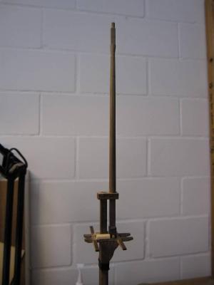
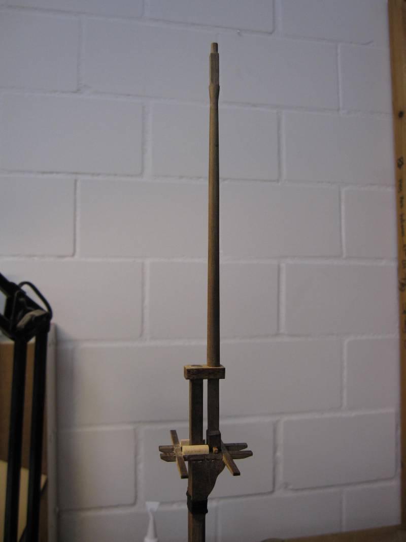
The next step is the assembling of the masts. The first is the most simple – the mizzen.
Having no turning lathe I just use a file or a small plane and a drilling machine to form the different parts.
On each mast I work from top to bottom. First I file all the square parts and the round parts are made into 8- or 16-sided polygons.
Then I put the mast - with some extra length on the lower end - into a simple handheld electrical drilling machine.
To form the round parts I use sanding paper of increasingly fine grade with the other hand.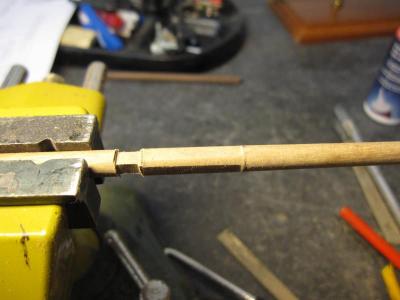
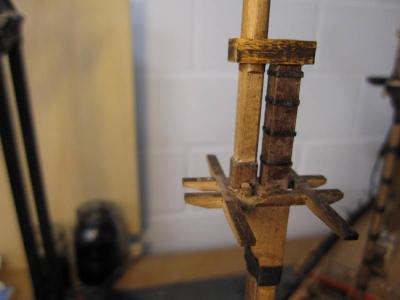
Lower end of main topmast

Mainmast parts ready to be glued togetherWith this kit there is again the problem that the manufacturer expects you to file a dowel of 6 mm diameter into a 6 mm sided square and I still don’t figure how to do that. (Recent repetition of basic geometry problems with my daughter didn’t help.)
So I made the square part of a piece of the next thicker dowel and glued it to the rest. To give some more strength I used a pin to put the parts together.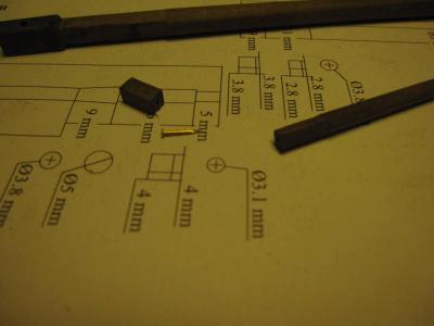
Lower end of main topgallant mast
On the fore topmast I tried a different solution: a tenon was filed on the lower end and a suiting hole drilled into the extra part. Gluing the two parts together this way gave more strength.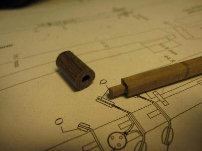
Alternative method on fore topmast
The finished mast foot
Another solution I saw in this forum is to form a smaller square and glue some planks onto the sides to make up the missing size.
In any case this part of the mast will be painted black, which will cover the traces of the working process, the difference in wood colour and the glue.(I will have to figure however, how to make the spare topmast to be placed across the waist with other spars. I think these spare parts there were left in raw wood (maybe oiled to protect them) and only painted when used.)
- billocrates and Mirabell61
-
2
-
Hi Frank
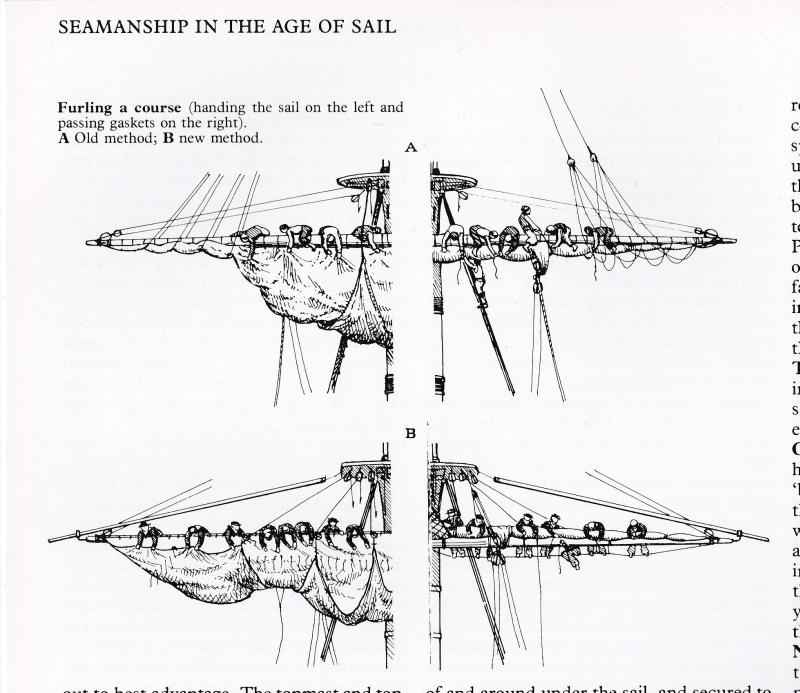
Some more about furling the sails:For deciding how I would make up my furled sails I was mainly using John Harlands ‘Seamanship in the age of sail’.
I tried to follow the method used to furl sails. It’s not a straightforward description and I’m not sure if I read it correctly. But the main steps seem:
- Pull up the sail with its gear. This would bring the clews to the clewline blocks which are near the slings or about 1/3 of the length of the yard from the mast.
- Then fold after fold of the sail was brought up its front, the last fold covering all the rest to protect the bulk
of the canvas from the weather. The furled sail rested on the front upper side of the yard.The clew would lie over the last fold back down the front side of the yard.
- Secure the sail with the gaskets.
In merchantmen the canvas was probably distributed as equally as possible along the yard. The whole description goes over several pages and sometimes overstrains my English.
The illustration is from the same source.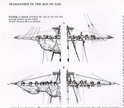
And by the way… I really think you underestimate enormously your abilities by using a book called …for dummies’ (Isn’t the most useful in the series perhaps ‘crash tests for dummies’?
 )
)
Cheers
Peter
-
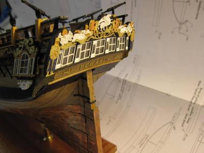
The port lids and several small parts, likely to break off, such as hammock cranes, hatchway rails or swivel guns will be put in
place after the rigging.
And yes, somebody will have to go over the transom with some blue and white paint to refresh the carvings’ colour. Most probably it will have to be me, which is only fair as I obviously didn’t always ‘mind the paintwork’.
- Mirabell61 and chris watton
-
2
-
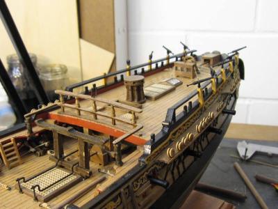
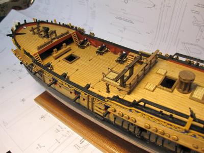
The general idea about colour was to use it as sparse as possible. So all the deck furnishing along the centreline was left in
wood. As far as I know, they did also use varnish to protect the wood in the 18th century.
The gun carriages are also just varnished. With those wooden ones this is fortunately possible and I like it better than red.(One of the comments to my first build log pointed very correctly to the rather ugly narrow sides of all the plywood parts. He was right of course and later I did try to mask them, where still possible, according his suggestion with wood colored paint. On future builds I will do this before assembling and building in.)
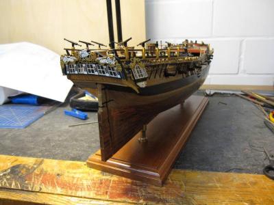
A lucky shot against the sun rising behind the forecastle

- granta, Mirabell61, billocrates and 1 other
-
4
-
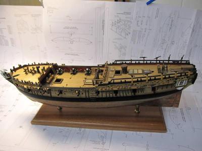
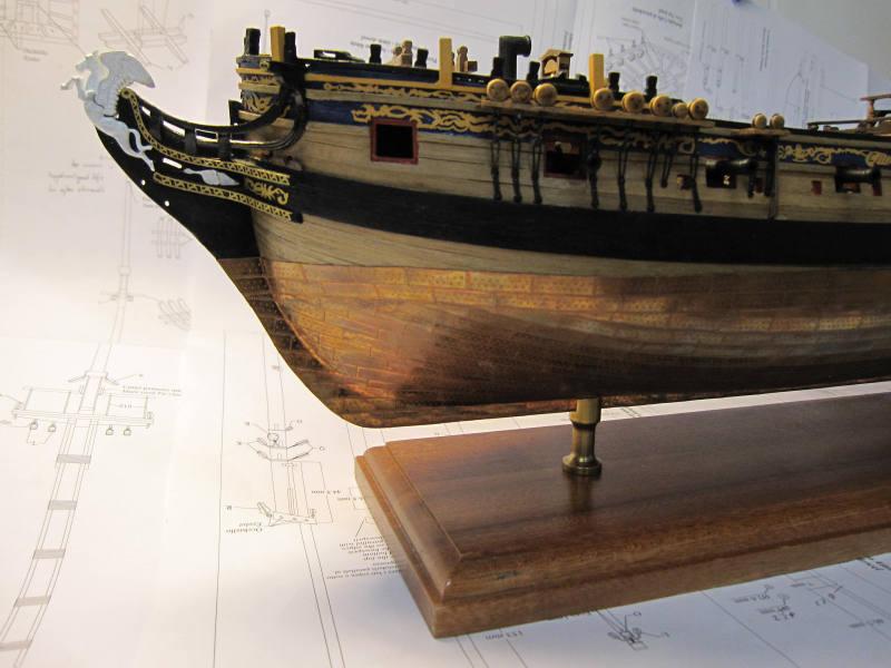
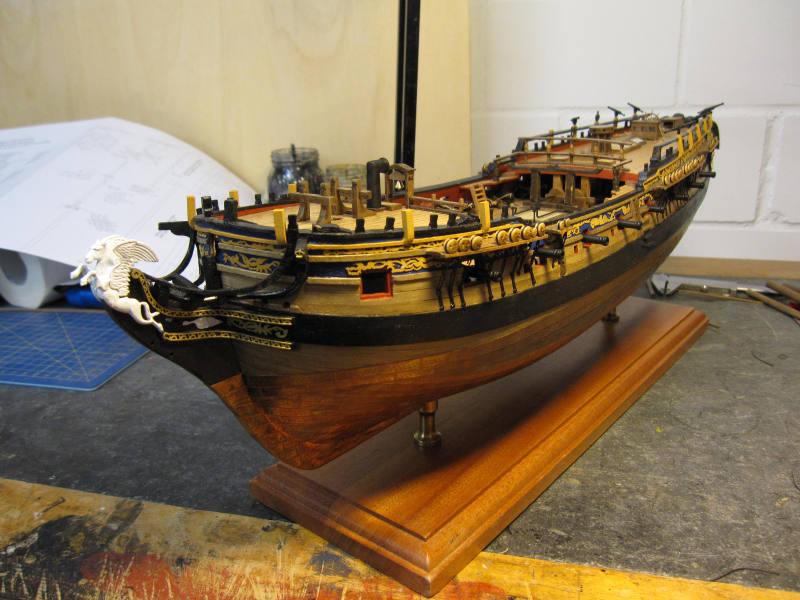
Finally the almost finished hull was fixed on its stand.

- Kathy Teel, Mirabell61 and billocrates
-
3
-
Hi Frank
Weeeel … my friend, since you asked …
The color of the sail looks nice, worn and a bit shabby; I think that’s what you are looking for. The way you fixed the sail to the yard looks fine as well. But…
After checking all my clever books I think that the furled sails should look different (at least on a warship, where you have plenty of hands to furl the sails). When furling the sails they took the sides in and up and then rolled it up the front to form a roll, which is thicker towards the middle, with just the two lower corners falling forward over that roll and then all the lines were straightened.
It’s a bit difficult to explain as I’m actually sitting in a hotel in Far East and don’t have those clever books with all the correct terms available.
I try to show what I mean with a picture of my Granado’s furled sails.
I had those sails made by a seamstress with just the vertical seams and the seams around the edge and then sewed a boltrope around the sail. Then the sail was fixed to the yard and then furled and only now the yard was fixed to the mast. The furling went easier with the sail dampened.
I am not sure how smooth your sail material actually is but usually it’s still rough-textured. Just use the very finest cotton you can find.
I don’t mean to criticize your work - heaven forbid!
 – I am just giving you my honest thoughts and still think yours is a really outstanding build.
Take care
Peter
-
Thank you, Aldo.
I’m sure your scratch build oven will look much better than mine.
Cheers
Peter
-
Hi Aldo
Great build and superb quarter badge! I look forward to your further improvements and regret that it’s too late to include them myself.Thank you for sharing.
Take care
Peter
-
Hi Frank
Thank you for the very kind remarks.
I look forward to how you make the sails. I’m still undecided. On the last boat I asked a professional seamstress to sew them. But her finest seams still look oversized.
I might try the method of pulling threads I found in one of the old forums. But this still leaves the seams around the edges…How to mix pictures and text – that’s rather easy on the new forum.
You must use the ‘More Reply Options’ option. If you now upload your picture to your unposted reply you see it at the bottom just above ‘Attach Files’. Below the small picture of the file you see 2 possible actions: Add to Post ¦Delete. If you click onto ‘Add to Post’ you create a text-placeholder in the text section where the cursor stands. This placeholder can be moved around like any text block. If you now push the button ‘Preview Post’ or ‘Add Reply’ the post will be displayed with pictures and text mixed.
Take care not to scrape yourself on those barnacles!
Cheers
Peter


HMS Pegasus by flyer - FINISHED - Victory Models
in - Kit build logs for subjects built from 1751 - 1800
Posted
Something more about my shortcuts in the rope work:
On my first one and a half models I tried to do rope work as close as possible to the original. Of course I wouldn’t splice but at least try to give a stropped block a close to the original impression and do the seizing by the book. It took forever and the result would nevertheless make any decent bosun stare. This was probably the main reason for the Wasa to stay half finished for over 10 years. When I restarted ship modelling a few years ago I tried to expedite rope work so as not to lose motivation again after half a model. That has carried me far into the third model (after finishing Wasa first).
Now about my lazy shortcuts:
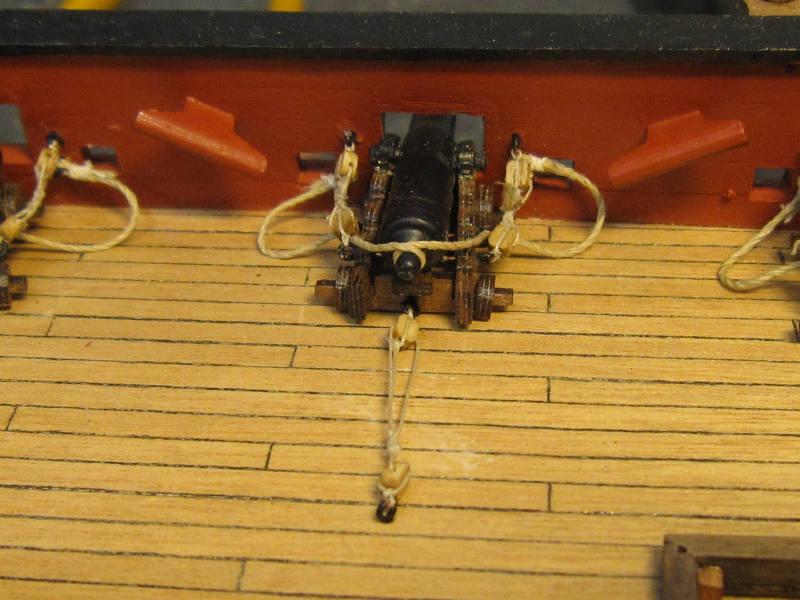
A block is first held with a single knot. Then a seizing holds the line and the loose end together.
To put on a seizing I use now a row of 5 to 7 slings as in the second picture. The ends get a double knot and all is fixed with diluted white glue.
Where a block was held with a single strop around a yard with the 2 eyes lashed together I use a reef knot as an approximation.
Of course the bosun will still stare but luckily the stare is diminished by 1/64 and I’m going to hide behind the mainmast if the he is nearby. And the work is done in a reasonable time.
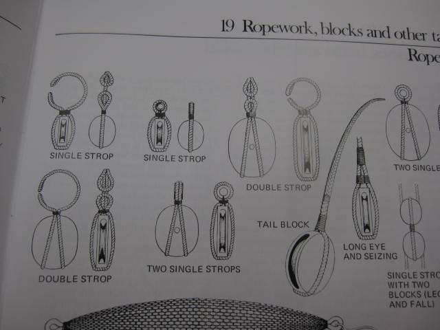
The picture here shows the stropping of blocks as we all know how it should be.
Putting on a ‘seizing’
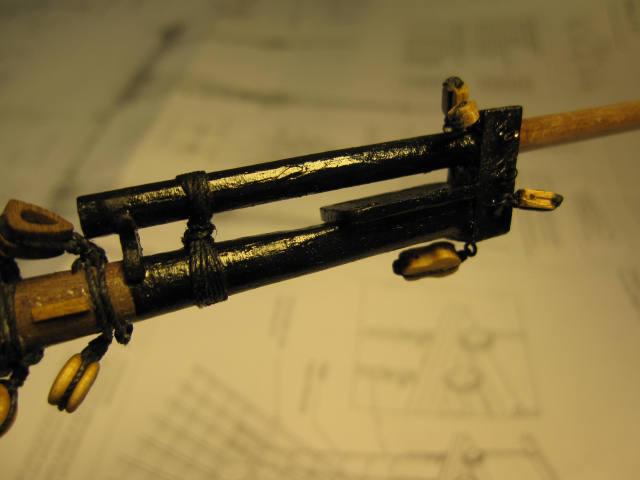
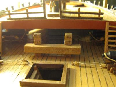
Two ends of line with a block ‘stropped’ in each are laid around the end of the boom and on both sides of the boom a ‘seizing’ is put on.
The result
Double blocks knotted close to each other into the line which is closed around the boom with a reef knot. 2 short seizings hold the blocks.
Result seen from above