


flyer
-
Posts
1,011 -
Joined
-
Last visited
Content Type
Profiles
Forums
Gallery
Events
Posts posted by flyer
-
-
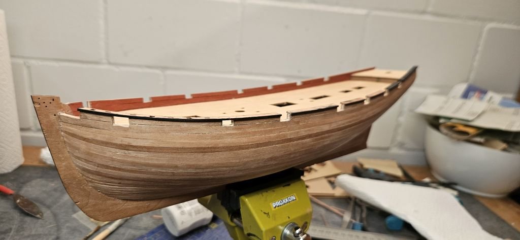
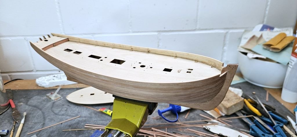
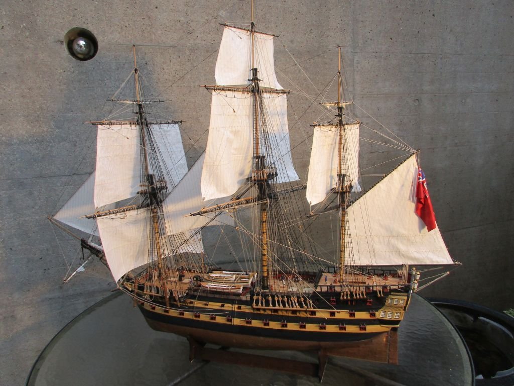
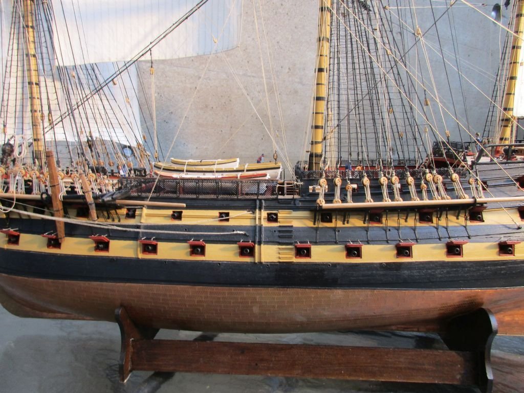
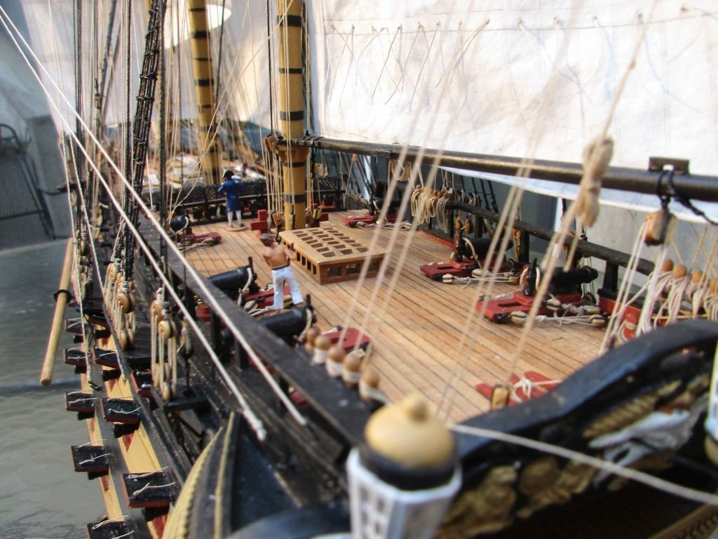
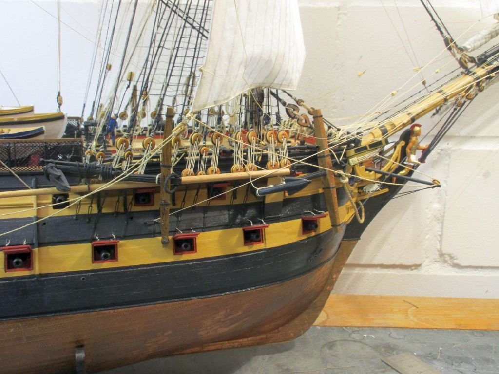
Next step was installing the deck and planking the inner side of the bulwark. Below the two 4mm planks I added an additional 1mm strip. This gives the bulwark a bit more height and could be an approximation of the waterways.
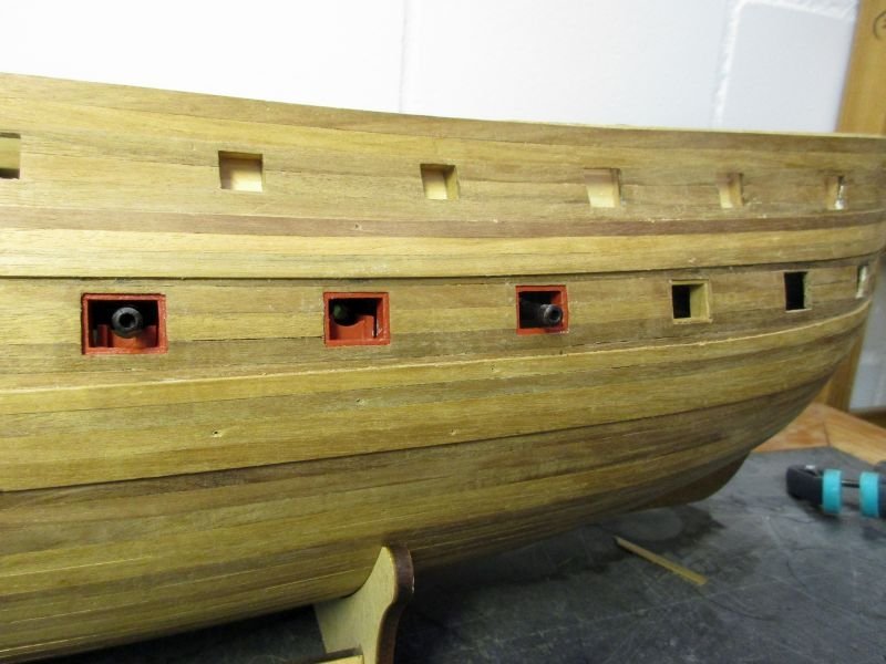
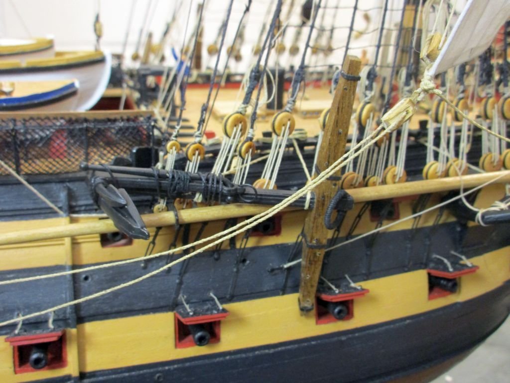
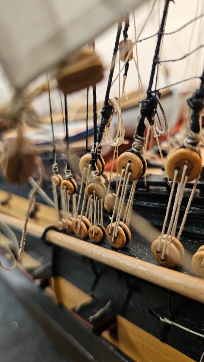
Then I marked the positions of the gunport openings with the help of the provisionally installed drift rail. The openings were the filed down to 5mm above deck level. After some final trimming of the bulwark top, the rails were glued on, the required slots cut out and the gun ports trimmed.
During that process I noted that the foremost gunports (which are covered by the drift rail) don’t work because the drift rail conflicts with the cannon. After rechecking the instructions as well as the size of the gun I decided to let that stand but would grant the skipper the use of a saw when he sees the need arise to use that ports in earnest.
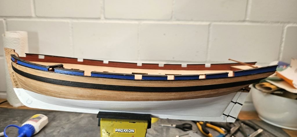
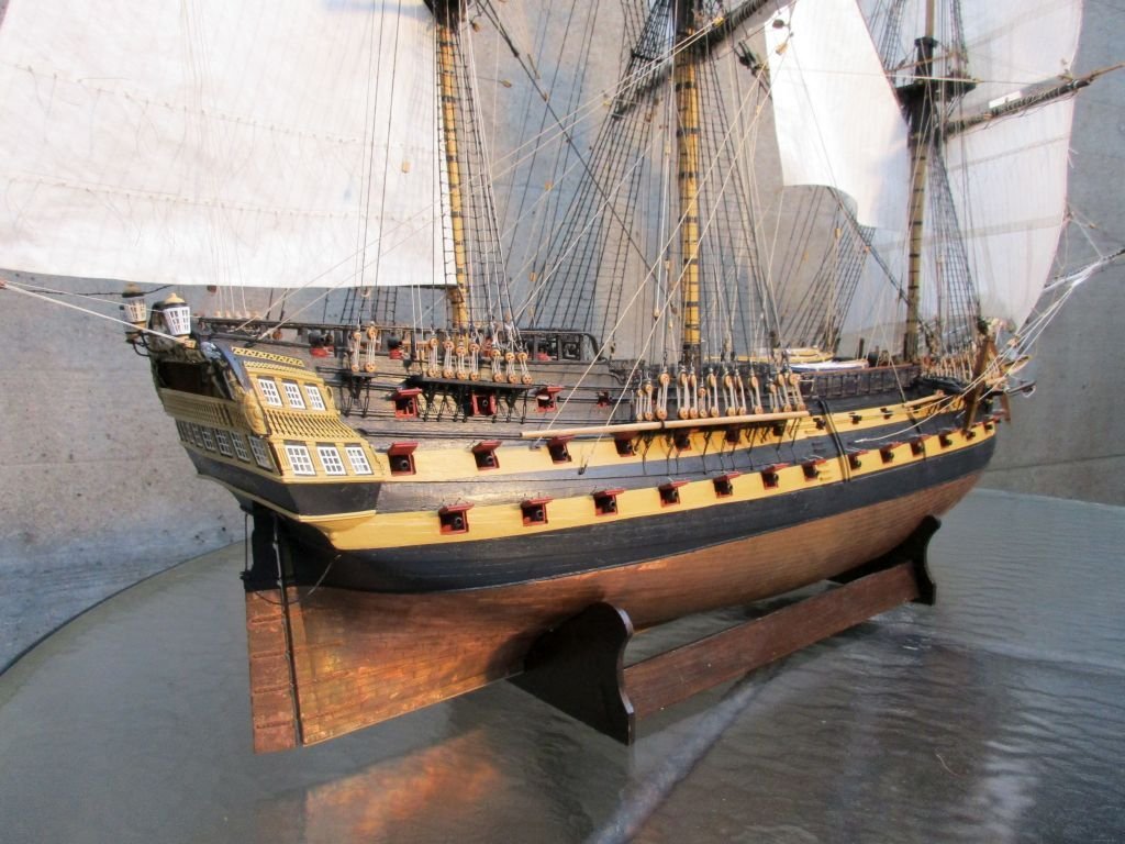
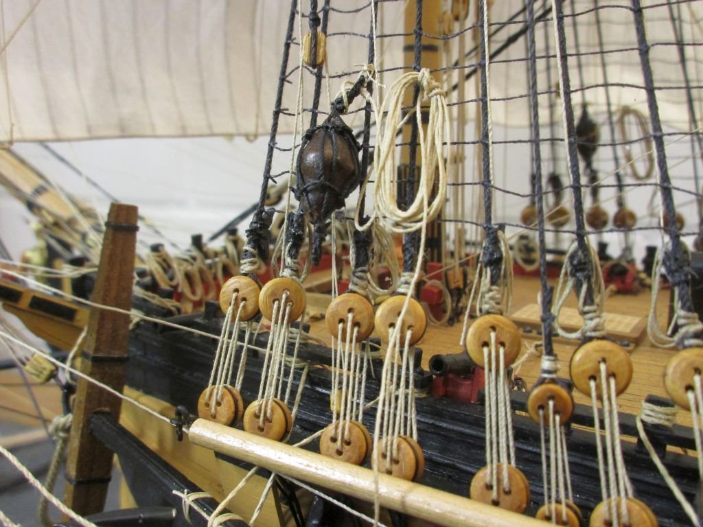
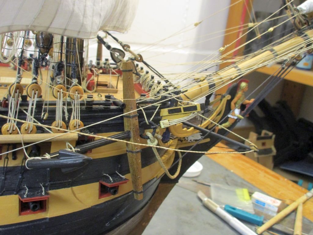
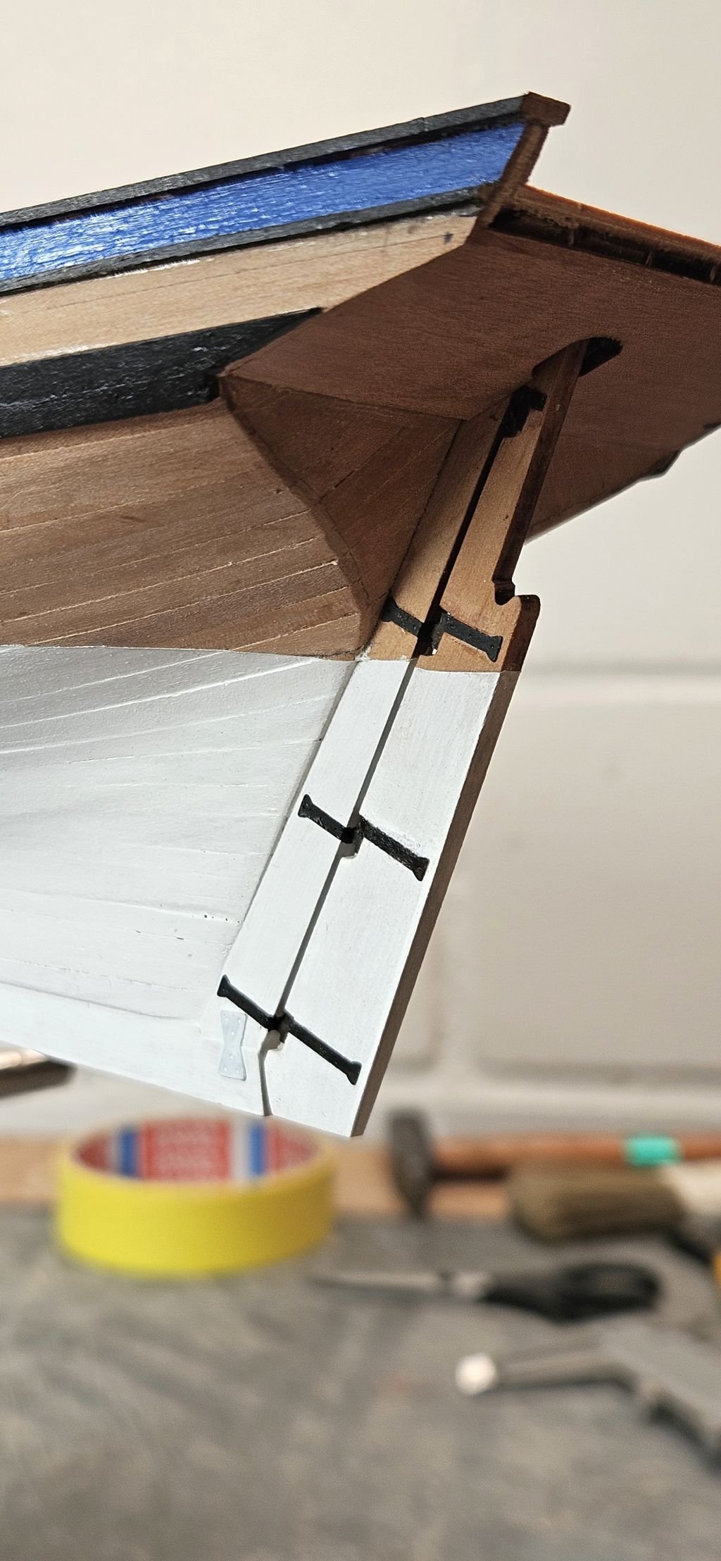
Now the strips marking the sheer rails and finally the main wales were glued on in the appropriate height.
For better definition of the colour, I tried to paint all parts as far as possible before glueing on. This is helpful when installing the inner bulwark planking but worked as well on the wales.
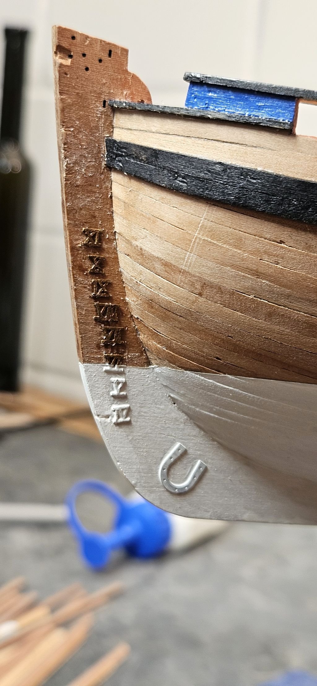
Now I did place the draught marks and horseshoe and fish plates on the keel.
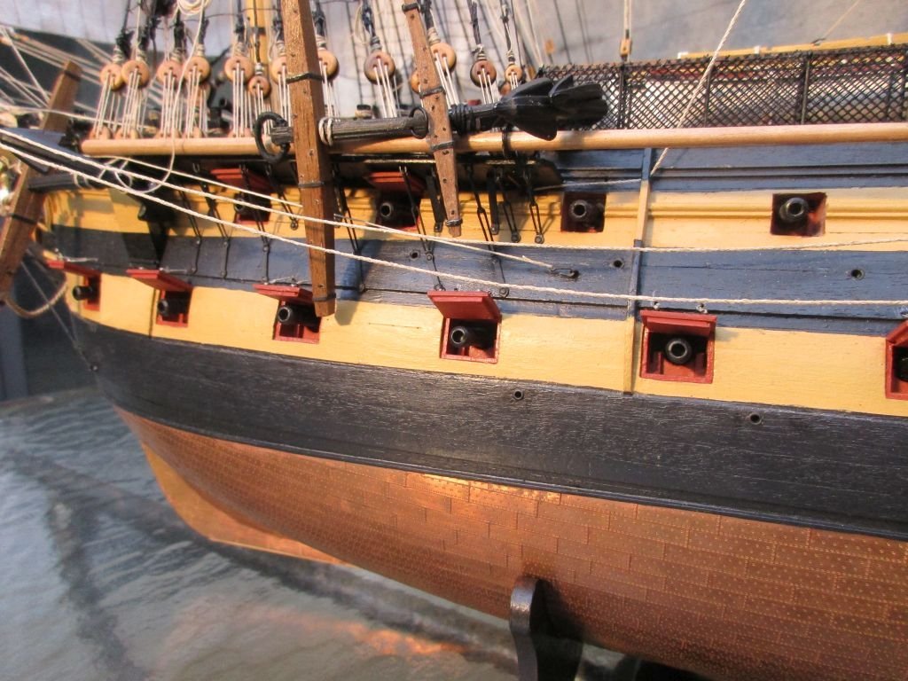
With a mixture of whitewash, dull white and about 5% dull black I painted the lower hull and the lower part of the rudder. The rudder fittings were blackened and glued onto rudder and hull. The rudder is only provisionally fixed.
I deliberately painted over the keel plates and the lower drought marks as I consider them part of the construction and they may benefit from the protective cover with white lead paint. On the other hand, I left the rudder gear blank as it is part of a mechanical device which should move freely and may need to be occasionally checked for wear and tear.
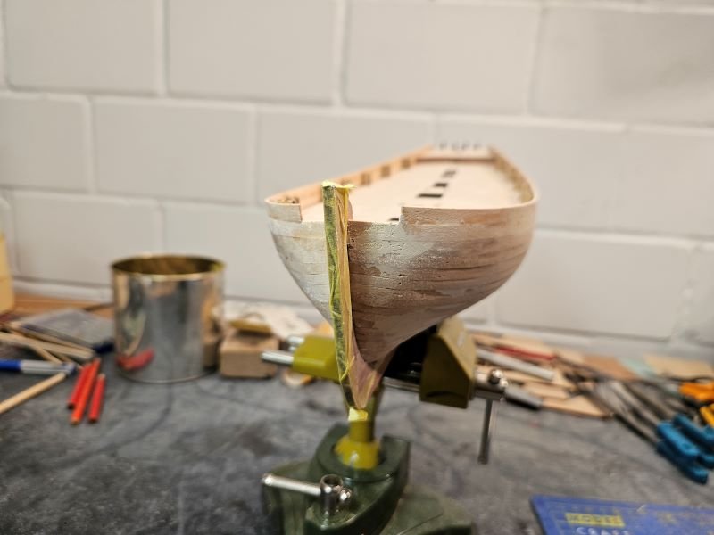
Trimming the rails
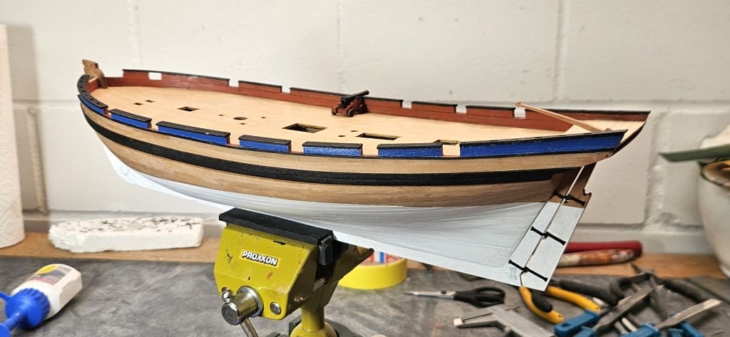
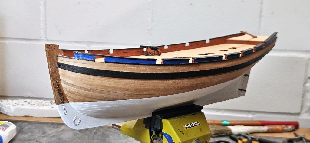
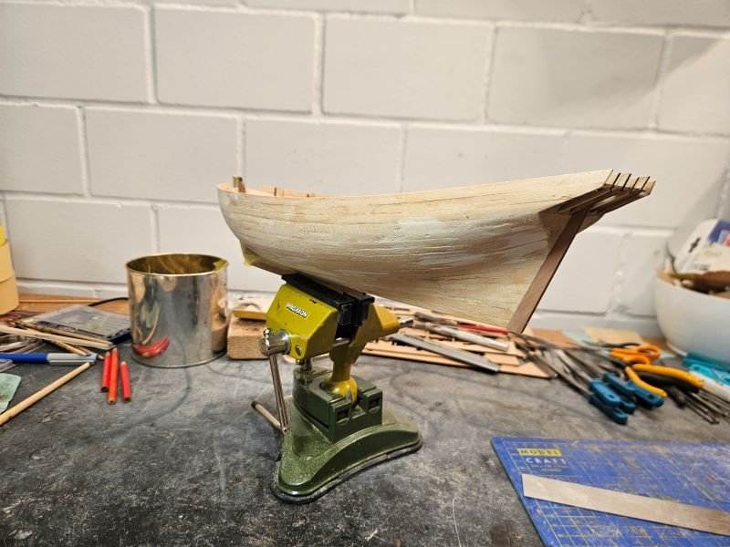
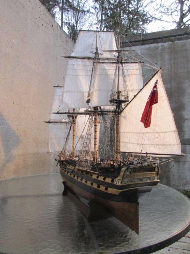
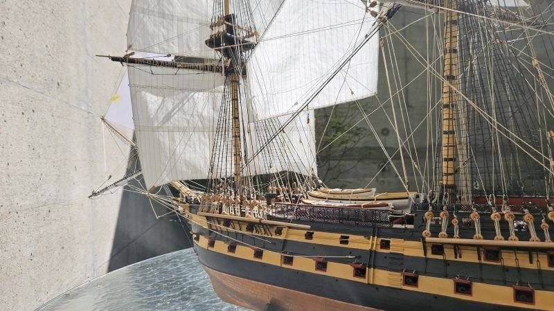
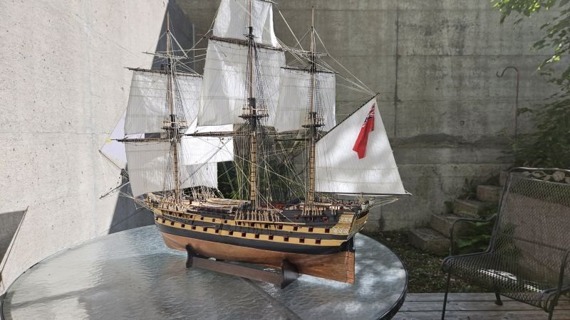
Hull almost finished

rudder

Seems one of the carpenters was a bit careless with his axe
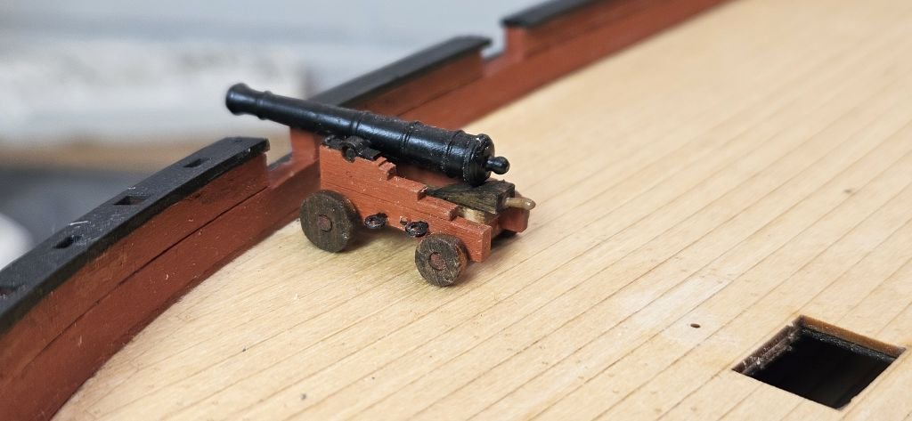
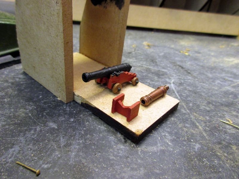
6 pounder gun
looking elegant
- Knocklouder, brunnels, ccoyle and 4 others
-
 7
7
-
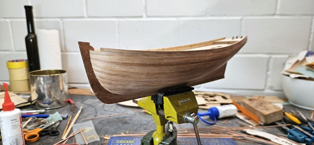
The second planking is now finished. It took rather long due to being a bit fiddly (and my sometimes lacking motivation).
The outcome is unfortunately to my liking. Unfortunately, because I intended to paint the lower hull with an off-white paint. Now with the quite acceptable planking I’m having second thoughts about covering my woodwork…
Next the wales and different wooden strips will be placed ‘from inside to outside’. The height of the bulwark was set somewhat by eyeballing and is now too high. I will install the deck, mark the height of the bulwark on the inside, sand it down and measure the position of wales and decorative strips on the outside from the top down. Nex time I build this kit I will take care to correct the upper edge of the first planking to the correct height above deck BEFORE starting the second layer!

- ccoyle, Knocklouder, rcweir and 3 others
-
6
-
The shipwrights in my wharf worked rather slowly lately. After Bellerophon any project seemed a bit trivial.
A longer inactive period has now ended and they are set to proper work again.
I used the beautifully laser engraved lower deck to try different methods to caulk the seams. But neither following the seams with a sharp pencil or fine marker nor filling the seams with black paint and scratching the deck clean again produced acceptable results.
Finally, I decided to use the main deck just as it is, with a layer of clear varnish.
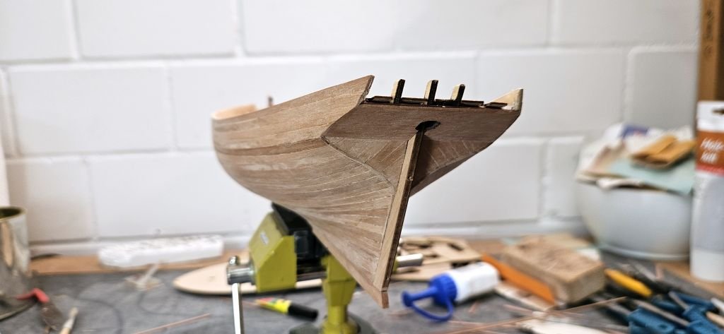
Now I glued, filled and sanded the first planking layer. During that task I found that my worry about perhaps building a too simple kit was rather invalid and the task was as demanding as ever but fortunately included a much smaller hull than the last one.
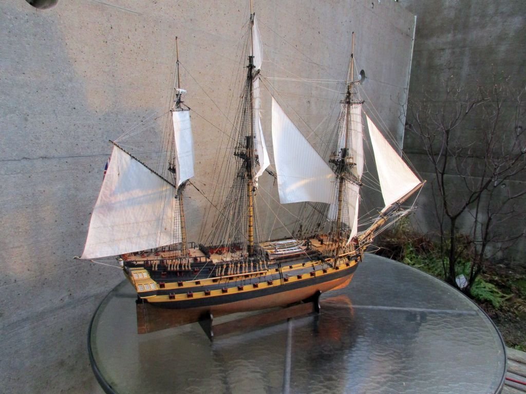
I love the elegant lines of Alert’s hull
- chris watton, Knocklouder, rcweir and 4 others
-
7
-
Hi Techtonic
Thanks for the hint and congratulations for finishing that monster. And what a lovely result you got and in such a short time! Did you ever sleep?
About using others’ ideas in one’s own build: I’d rather call it borrowing because I don’t keep them but preferentially pass them on. Some details you found in my log were other’s brainchild. And anyway, I’m rather flattered that you found my example helpful.
Cheerio
Peter
-
A smaller boat is very high up on my wish list too. Logic dictates that any ship definitely needs at least one boat to communicate with the shore and for various other tasks.
In ‘The Naval Cutter Alert’ Peter Goodwin writes about boats:
“… For conveying stores, dispatches and officers and crew, the Alert carried a single boat. (…) In all probability, 6- or 8- oared cutters varying between 12ft and 18ft in length were employed. Alternatively, a long boat either 14ft or16ft in length may have been used. (…) In December 1763 one such (Admiralty) order decreed that during winter only one small 4- oared boat should be allocated and that it should be carried rather than towed to avoid being lost. An order of June 1779 mentions 16ft boats for cutters while another of July 1783 recommends the addition of a second boat.
(…)
When not in use the boat was stowed on the upper deck between the main jeer and topsail bitts and the two elm tree pumps abaft. (…) When required the boat was either swung out or hoisted inboard from tackle suspended from the boom. Should the vessel encounter action the boat was towed astern…
The ships boat also served to convey boarding parties onto vessels ordered to be searched; and for laying out the kedge anchor for warping the ship; or for towing the ship when becalmed. ”
A contemporary model of the naval cutter Hawke kept at NMM shows a small boat stowed on deck.
I guess that all this information is also valid for any other ship or smaller vessel. So, each vessel must have had at least one boat. It may not always be shown on contemporary models because smaller vessels may have towed it quite often but for heavy weather there must have a been a possibility to take it aboard.
I really would appreciate a model of a small 12ft or 14ft boat which would also fit all your small models. With a small stand to place it on deck included, you should be able to sell at least one model to every serious model builder who bought one of your smaller kits 😉.
Peter
- Canute, thibaultron, Pitan and 9 others
-
12
-
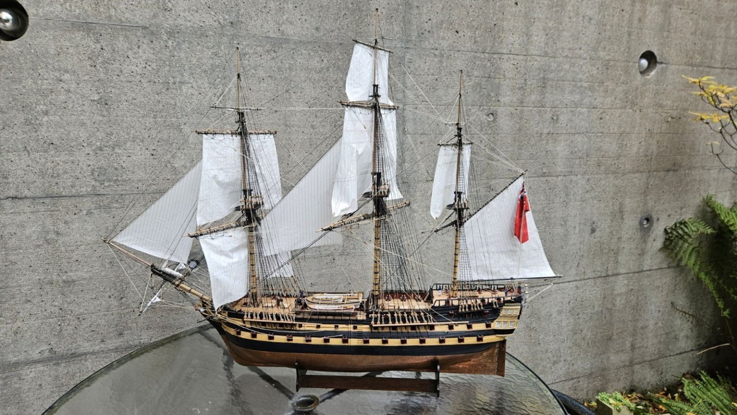
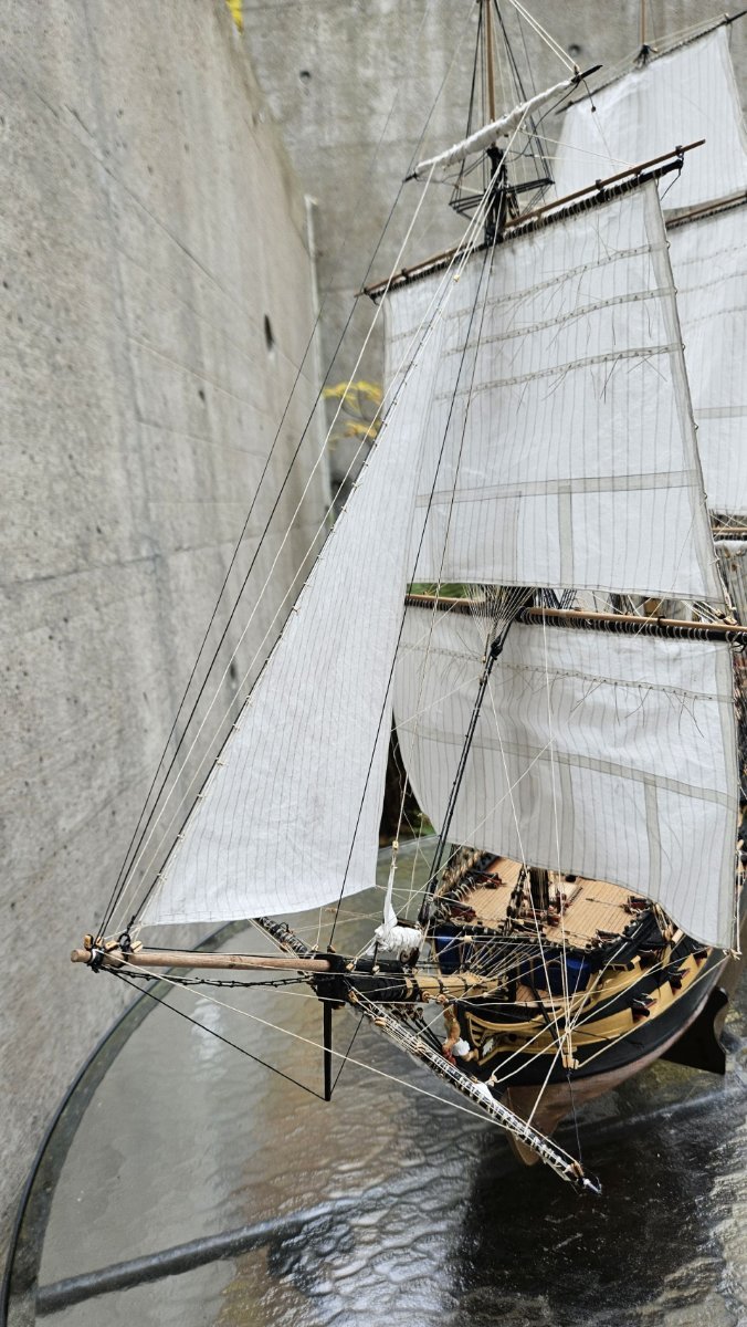
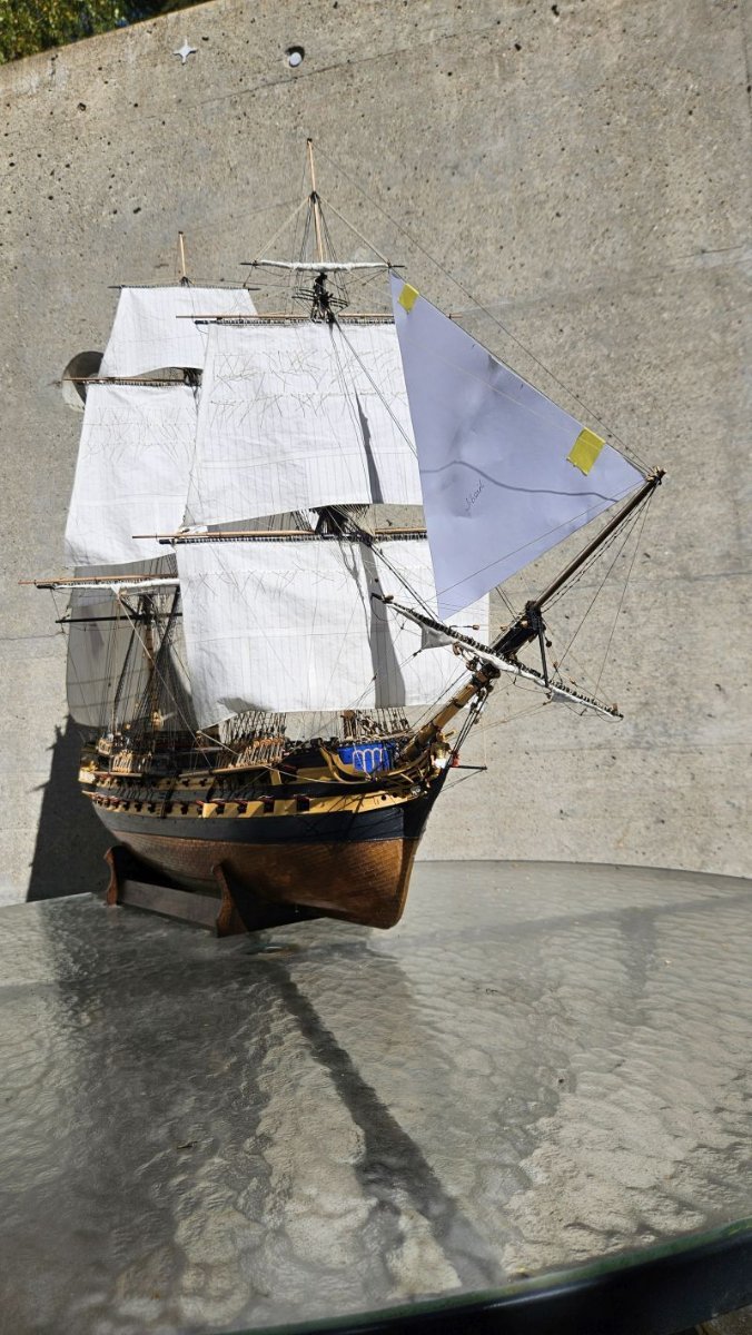
The Naval Cutter Alert by flyer - Vanguard Models - scale 1:64
The next project is another step ahead in kit quality – a Vanguard Models kit. The HMS Vanguard kit itself was also a Chris Watton construction, however with his own line of products I believe he took quality one or several steps further.
Although the kit looks great, there are – fortunately - still possibilities to change it to my liking or even to improve it a bit. For additional information I will count on Peter Goodwin’s ‘The Naval Cutter Alert 1777’, a book of the AOTS series.
My first thoughts are:
The cutter must have a boat. With the kit I ordered Vanguard Model’s 18ft cutter with the intention to shorten it to 14 or 16ft to easier find room on deck. In the meantime, Chris Watton announced that he will soon offer a printed 14ft cutter. I will consider this or – if it is still too large – perhaps commission Caldercraft’s 14ft jolly boat.
Sails will be hoisted. But I will make my own as the kit’s ones are not to my liking.
The rigging layout could be changed to an improved and standardised cutter rigging without spread yard and with spreaders for the shrouds. However, right now, I think the kit’s rigging scheme has its very own charm and is not only confirmed by the contemporary model of the cutter Hawke but also by contemporary paintings of Charles Brooking. Decision to be taken later.
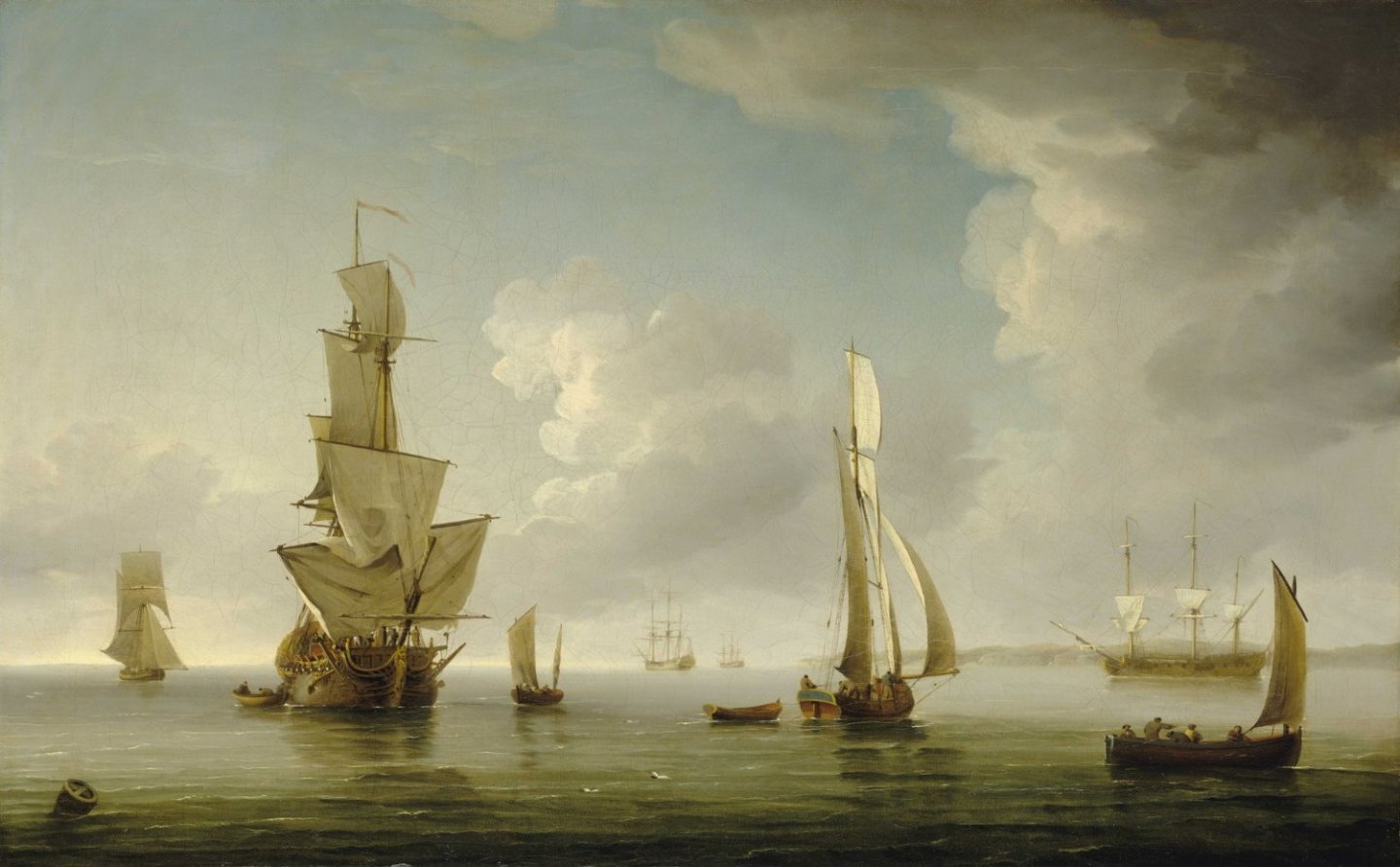
Shipping in Light Airs in the Thames Estuary by Charles Brooking 1723 – 56
-
Very nice!
This seems to be a 18ft cutter. Do you also plan to offer a smaller 12ft or 14ft boat, suitable for your smaller vessels, such as Alert?
- mtaylor, thibaultron and Canute
-
3
-
Hi Nils
As we would say in Swinglish: I pull my hat before you (ich ziehe meinen Hut vor dir).
Not only have you built another unique, detailed, outstanding gem but you also finished it in about 8 months! From scratch! Without plans!
Wonderful!
Cheers
Peter
- Keith Black, mtaylor, Canute and 3 others
-
6
-
Hi Allan,
And a happy new year to you too!
Yes, Lees mentions '...through blocks under the fore top...' several times and the drawings show those blocks fixed at the extremes of the trestle trees - except on page 102 where a 'double block is seized to the crosstree'.
I wonder if regulations in those times really went as far as to specify the exact locations of those blocks. Lees, in his introduction, mentions that his written sources mainly deal with size and dimensions. I guess that the actual run of the lines of the running rigging he shows is an average of the many but still limited number of models he studied.
I'm always tempted to follow kit instructions if they are not directly contradicted by e.g. Lees. Respectable kit designers may use Lees or their own research for the rigging plans and certainly try to be as historically accurate as possible. But even somebody like Chris Watton may have to use approximations sometimes to construct a practicable and sellable kit. And then sometimes I'm just lazy and tempted to take the easy way out.
Cheers
Peter
- Keith Black, allanyed and mtaylor
-
3
-
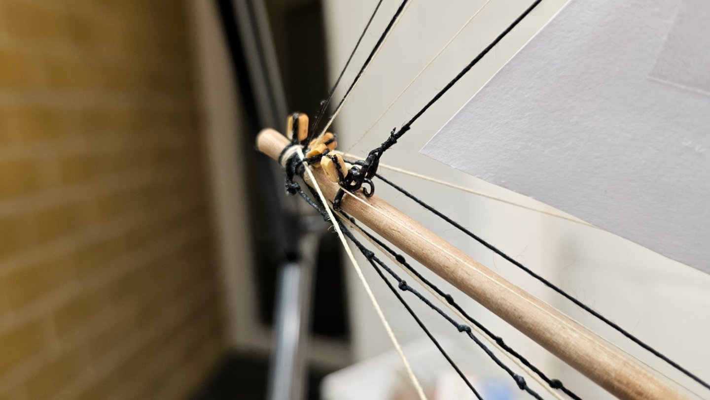
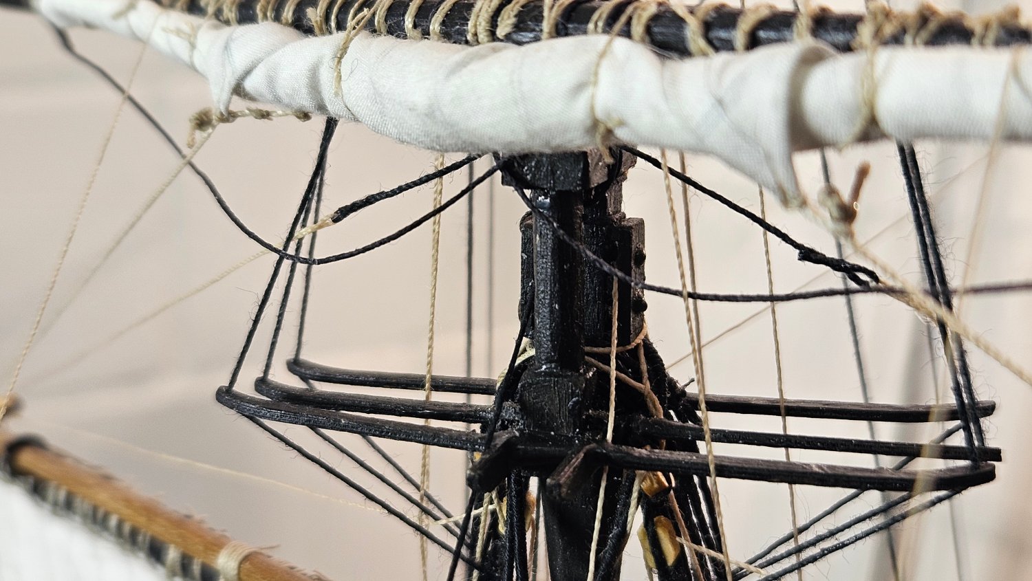
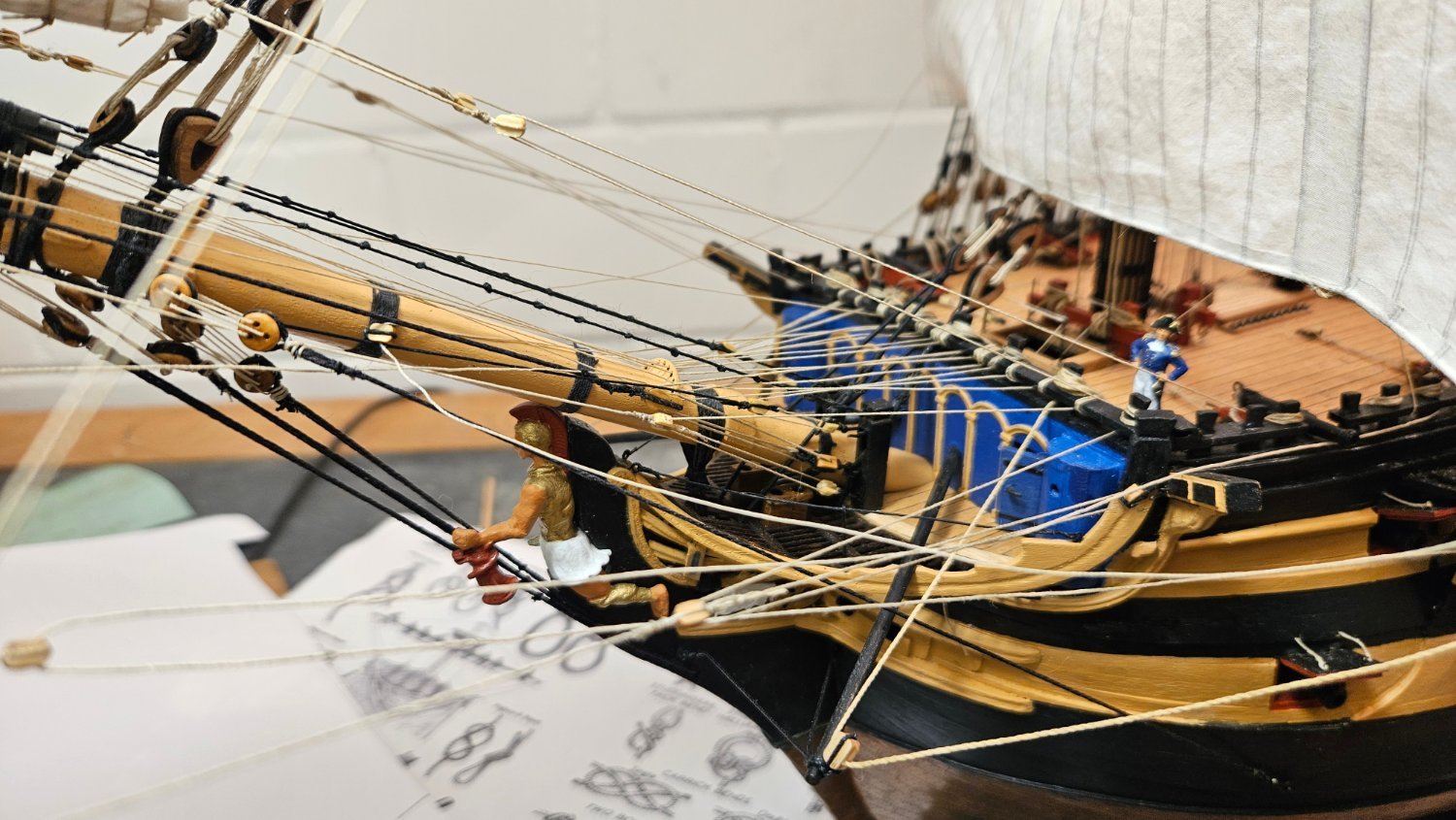
The question I tried to answer was about the green circled blocks in the 2nd picture of #1:
I took those as indication of having two identical rows of blocks on the forward and aft crosstree. The lines then are going through the identical blocks on each crosstree thus leading free of and above the fore yard, perhaps to give some space to brace the yard.
In Lees' book you find on page 73 top right an illustration for the buntlines, installed that way. (BTW on Bellerophon I used a similar arrangement also for the main yard.)
The two outboard single block pairs were thus used for the buntlines and the inboard double block pairs I used for spritsail and sprit topsail braces. This is confirmed by Lees again on page 101 respective page 105.
- Keith Black and mtaylor
-
2
-
conclusion
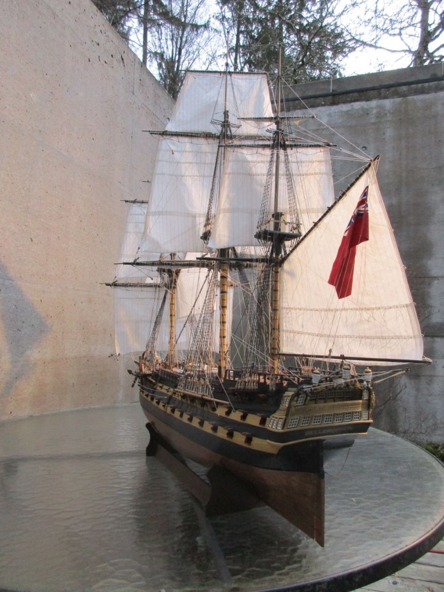
After more than 6 years, I'd say it was a rather longish journey but I really had a lot of fun along the way and it was definitely worth the effort. The outstanding quality of the kit and the possibility to build 3 different ships makes it easy to overlook a few shortcomings, such as questionable details in the rigging plan or the very questionable gun carriages. On the plus side are also things like the very detailed plans such as the sail plans, the boats or the many fine details to build bulkheads or stern and side galleries.
A perfect kit where you may build just out of the box without research or rounding out with additions might be just a bit dull - I will probably find out more about that with my next project.
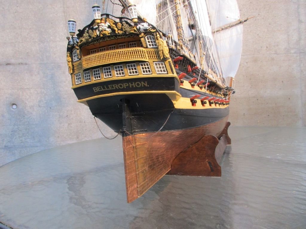
In any case this kit enables you to build a wonderful model of a 74, the backbone of the wooden walls protecting Great Britain during the Napoleonic wars. Finding a good enough place to present the rather large end result is another story...
a few final pictures.
-
Thank you all for the compliments as well as for all the support carrying me through this build.
And a very happy New Year to all of you!
Peter
-
changes, amendments and mistakes
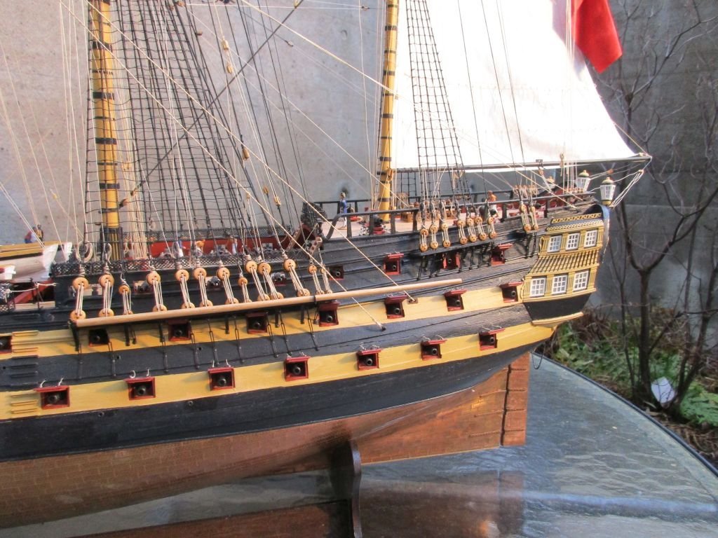
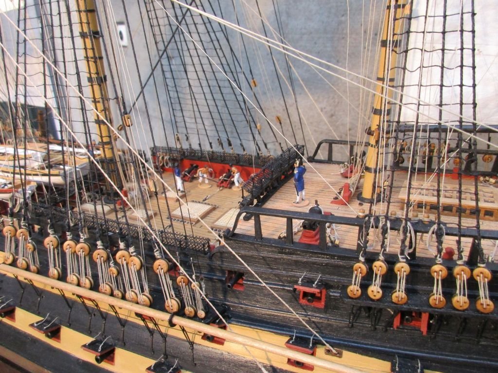
The biggest changes were the dummy gun carriages on the gun deck and the cast gun carriages, the stern decoration as well as leaving of the spritsail topsail and its yard.
The most rewarding improvement, in my opinion, were the dummy carriages. Thank you, Michael (md1400cs). On any kit which includes such dummy guns, installation of a sort of dummy carriage should be tried.
Minor amendments were the changed curve of the stern, the scuppers, the sails fabricated my way, the flag, shot garlands, the captains skylight, the taffrail, the rudder chains, the anchor bolsters below the fore channels, the traveler on the bowsprit, anchor buoys and several minor changes.
The biggest, uncorrected mistake is probably that I did set up the preventer stays above the stays, thus having to hang the staysails onto the stays themselves.
slightly reworked gun carriage for the upper gun deck and dummy carriage for the lower
gun port with dummy-carriage and -gun / carriage and no gun / gun and no carriage
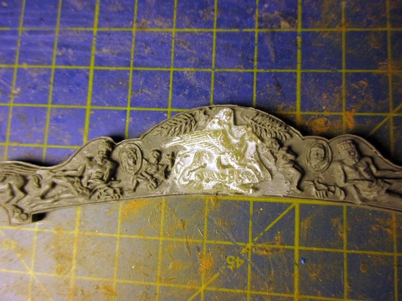
the elephant was scratched away and replaced by a epoxy-cast of Bellerophon
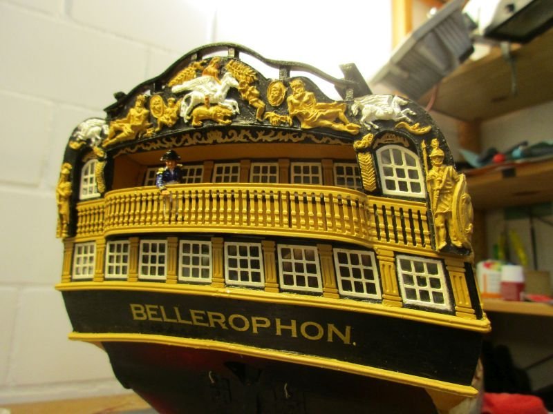
finished transom with new rail on top

spritsail without topsail and traveller on the bowsprit, holding the jib stay
- Knocklouder, KARAVOKIRIS, AON and 5 others
-
8
-
Thank you, Nils. When I see what quality you achieve, scratch building your Ergenstrasse, I appreciate your compliment even more.
Oh, and a very happy new year!
Peter
- Mirabell61 and Mr Whippy
-
2
-
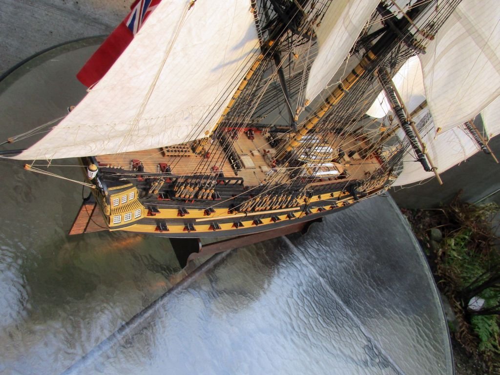
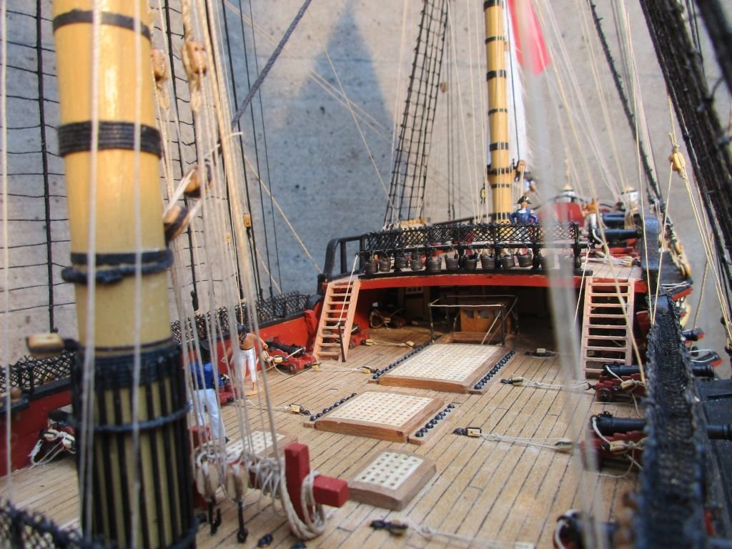
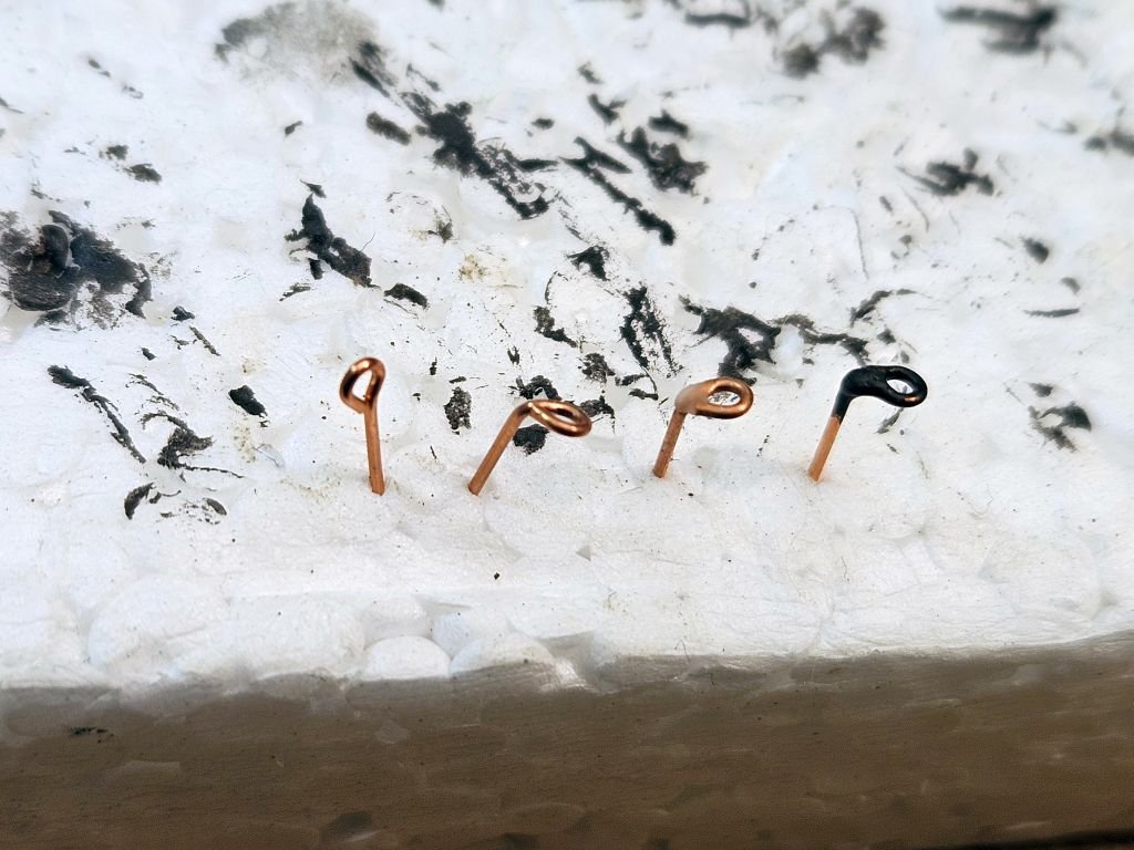
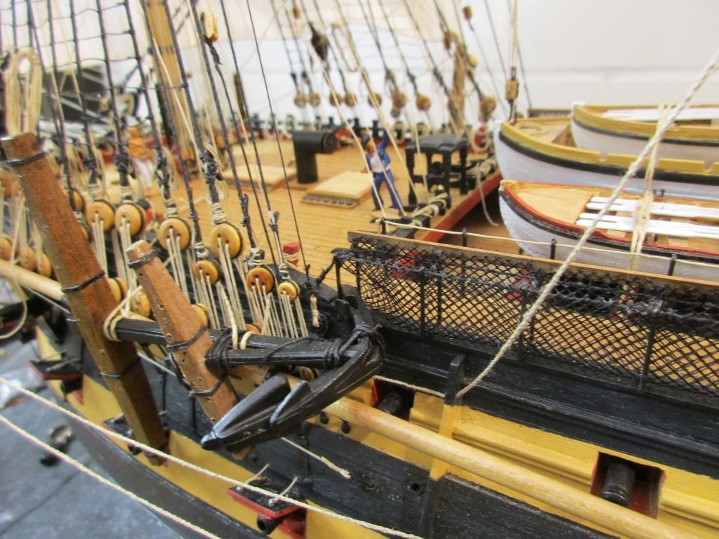
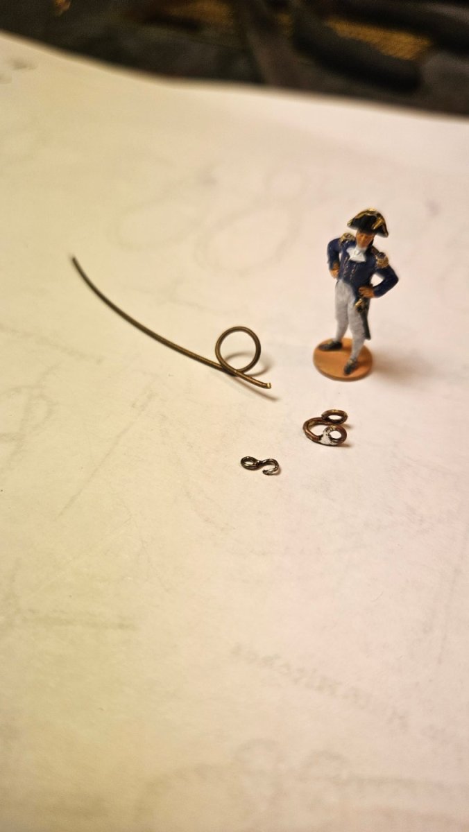
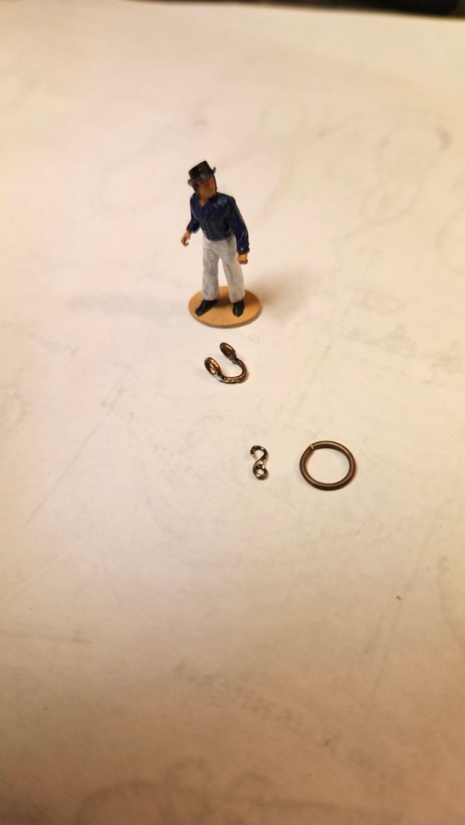
empty belaying pins and ringbolts, loose ends
Despite having to overcome a shortage of usable belaying points on the forecastle there were still a few unused pin positions on the poop deck.
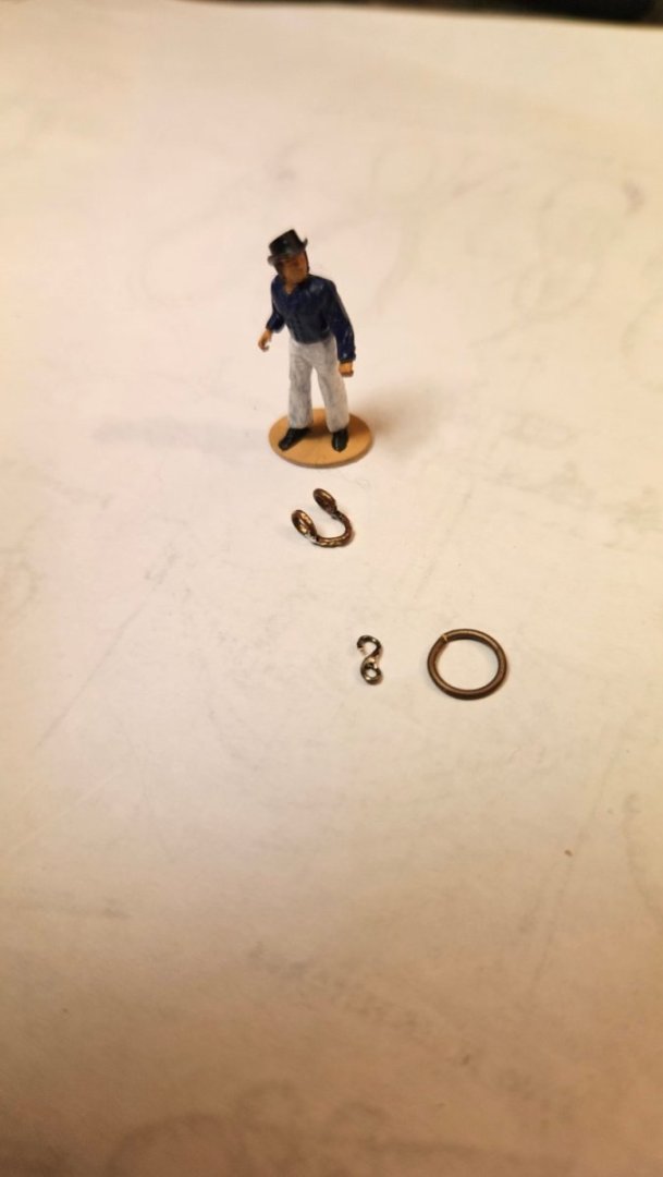
Also unused ring or eye bolt positions around main and mizzen mast had to be filled. The kit instructions put eye bolts into those locations. However I think that ringbolts, allowed to lie flat when unused, would be more sensible when mounted on the deck. I didn't find much about that in the web but thought it would be easier to run about on deck if you wouldn't have to fear to catch your bare feet in a ring, take a tumble and break your ankle.
To imitate a ringbolt with a small fixed ring which encloses the movable one tightly, I bent an eye bolt 90° and put a drop of glue onto it to simulate the fixed ring.
After fixing all loose ends I could find, finally...finished!
 the way I fabricated the imitated ringbolts
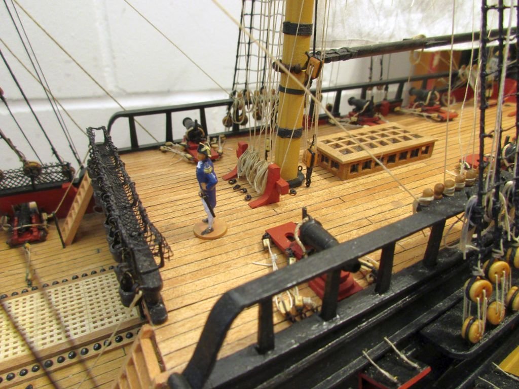
unused ringbolts around the mizzen mast foot
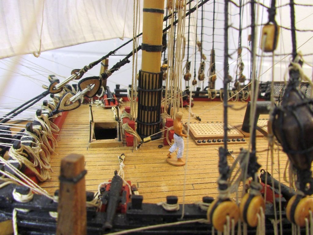
fore mast foot with eyebolt(with tackle) to the left and one of the empty ringbolts lying flat on the deck
moderately busy scene on the finished forecastle
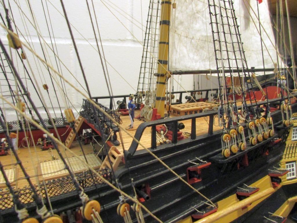
the skipper seems quite fond of his ship - and so am I...
-
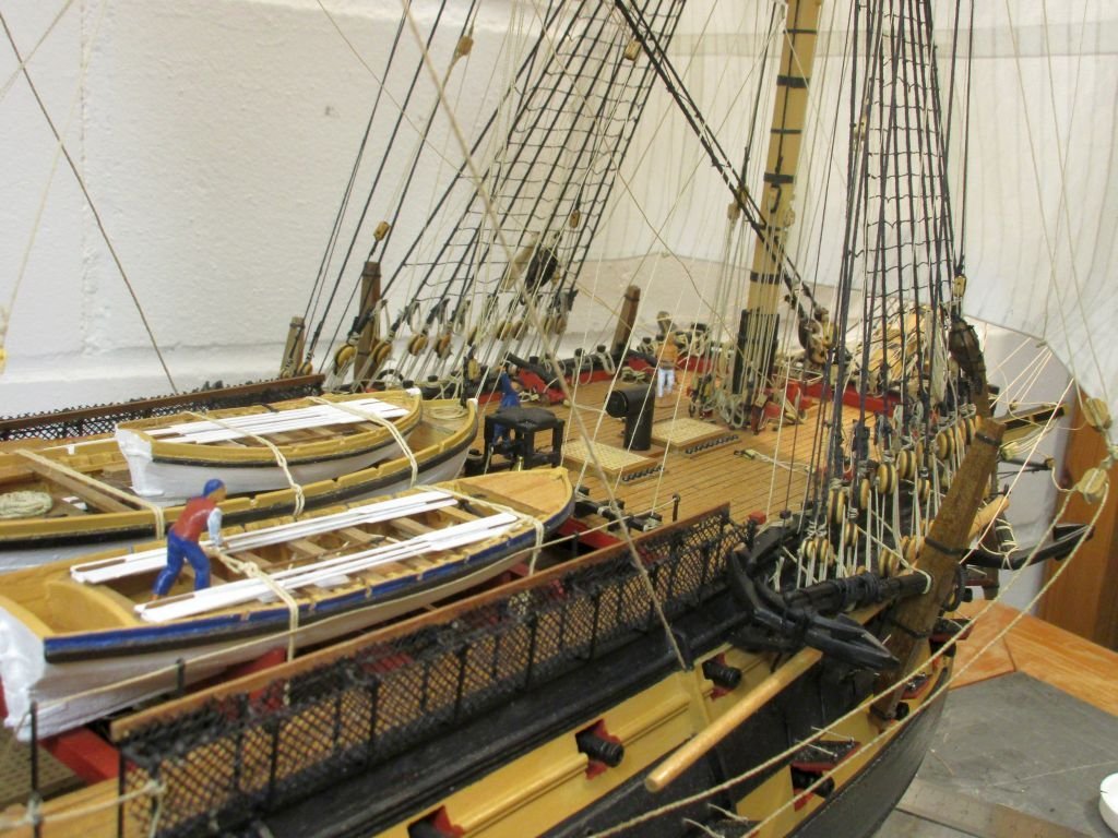
anchors
A suitable stream anchor was added to the 5 anchors from the kit, all completed and stored. A conflict for space occurred between the sheet and bower anchors and the lower stun sail booms. The only way I could think of, was to place the anchors on top of the booms. Thus, to set booms you have to move them from under the anchors.
Anchor buoys were formed with some 2-component putty and hung into the shrouds. As I understand anchors were buoyed and buoys should therefore be shown whenever a cable was bent to the anchor making it ready for use. For size I used information from John Harland who writes that '... the anchor buoy was in length one-quarter the length of the anchor shank, in diameter, one-eight...'.
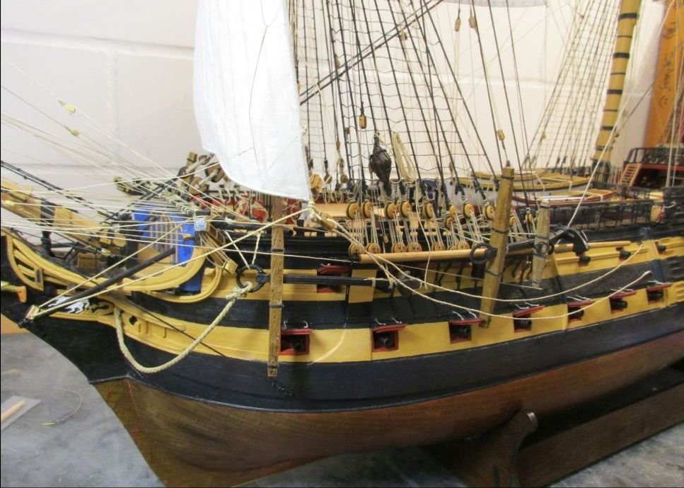
port side with sheet and bower anchors and the extra stream anchor lashed to sheet anchor
stream anchor
the cable is attached to the bower anchor and the cat block with tackle is hooked into the ring
starboard with sheet and bower anchors and the kedge anchor lashed to the sheet anchor
kedge anchor
anchor buoy stowed in the fore shrouds
 the buoy rope lashed to the anchor
- Techtonic, Ronald-V, GrandpaPhil and 6 others
-
9
-
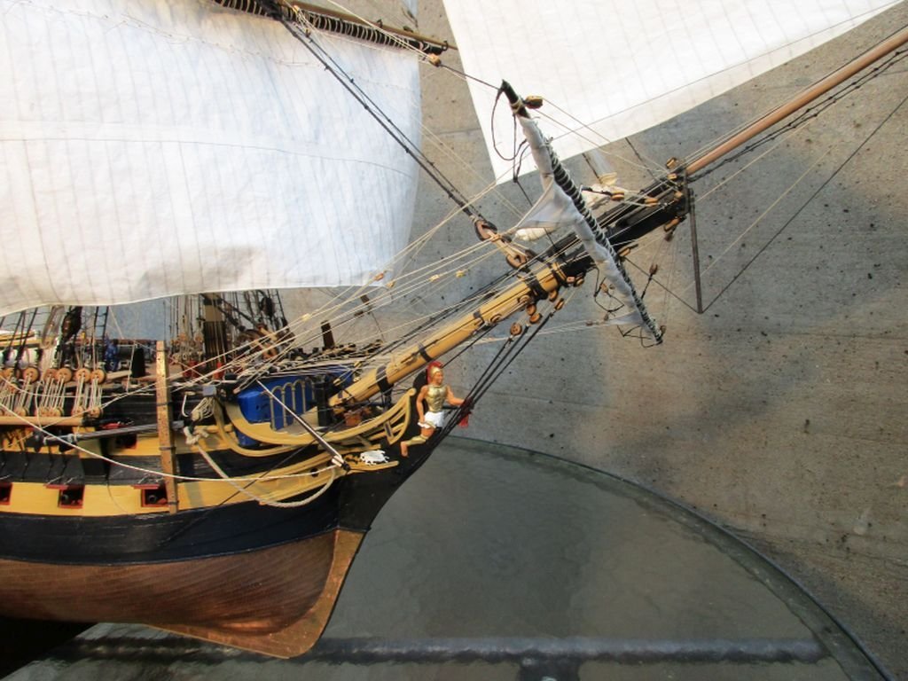
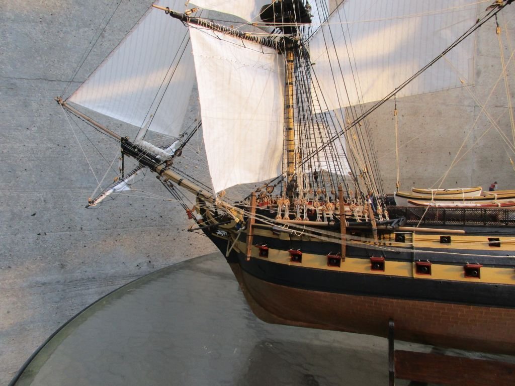
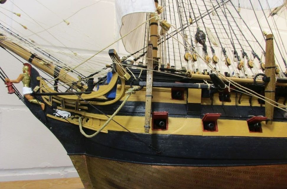
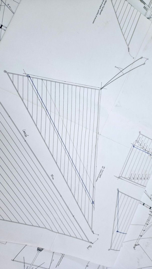
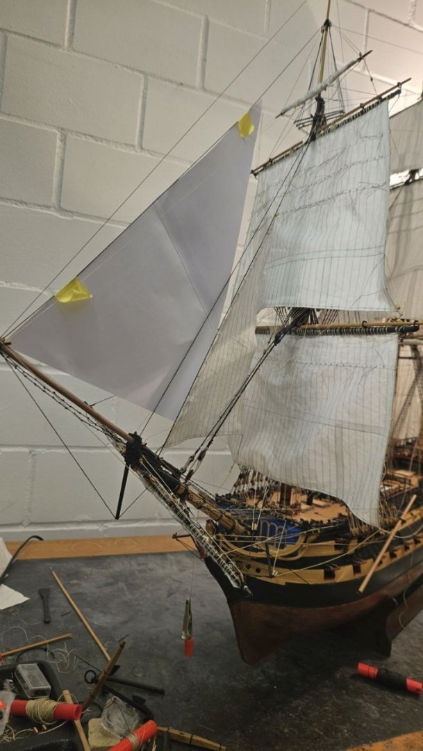
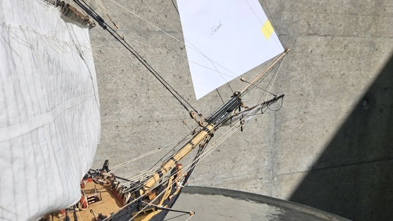
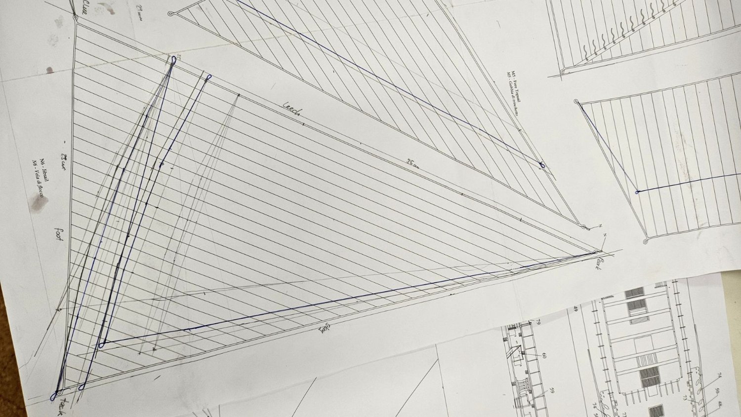
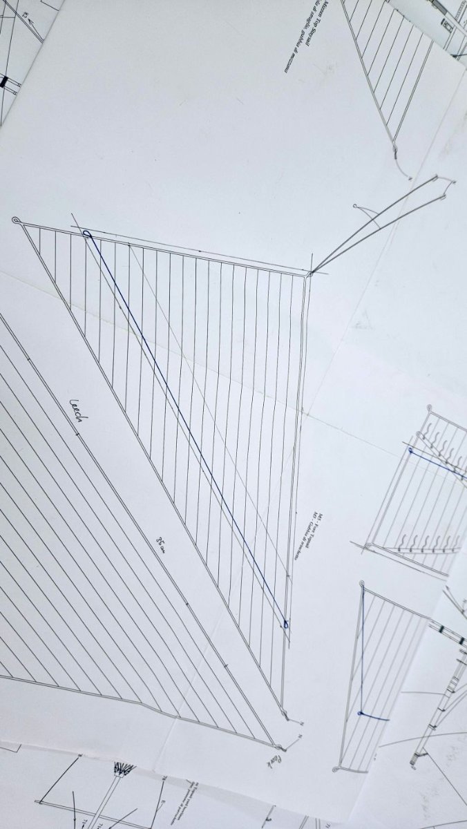
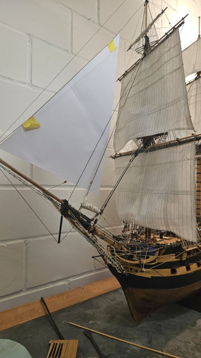
jib sail
Several tries were necessary to find an adequate size for the jib sail. To me it was clear, that the kit's plan for the sail was grossly unfitting. Trying to draw one following the description in James Lees in 'Masting and Rigging of English Ships of War' was more difficult than expected. Several attempts were tested with paper templates just to prove unsatisfactory. Finally I tried to use the same proportions in regard to rigging and the other sails as Pandora's jib in the ATOS series has. Judging by eye it looked about right.
To bend the jib to its stay I used again figure-of-eight robands. The tack was hooked into the traveler and the rigging set up with help of the kit plans and instructions and some clarification by Lees.
Now I only have to install the anchors, to check the natural hang of all lines and to clean up everything...
Oh yes, and to find a suitable berth for a rather big model...

trying to find the right size - the smaller blue outline is the final one
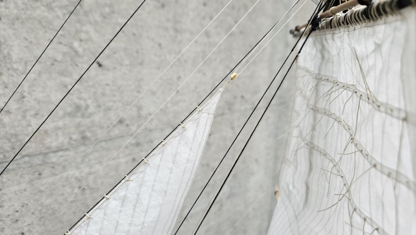
detail of the peak

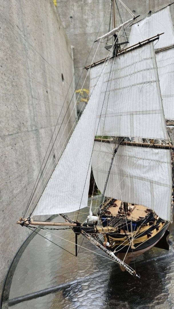
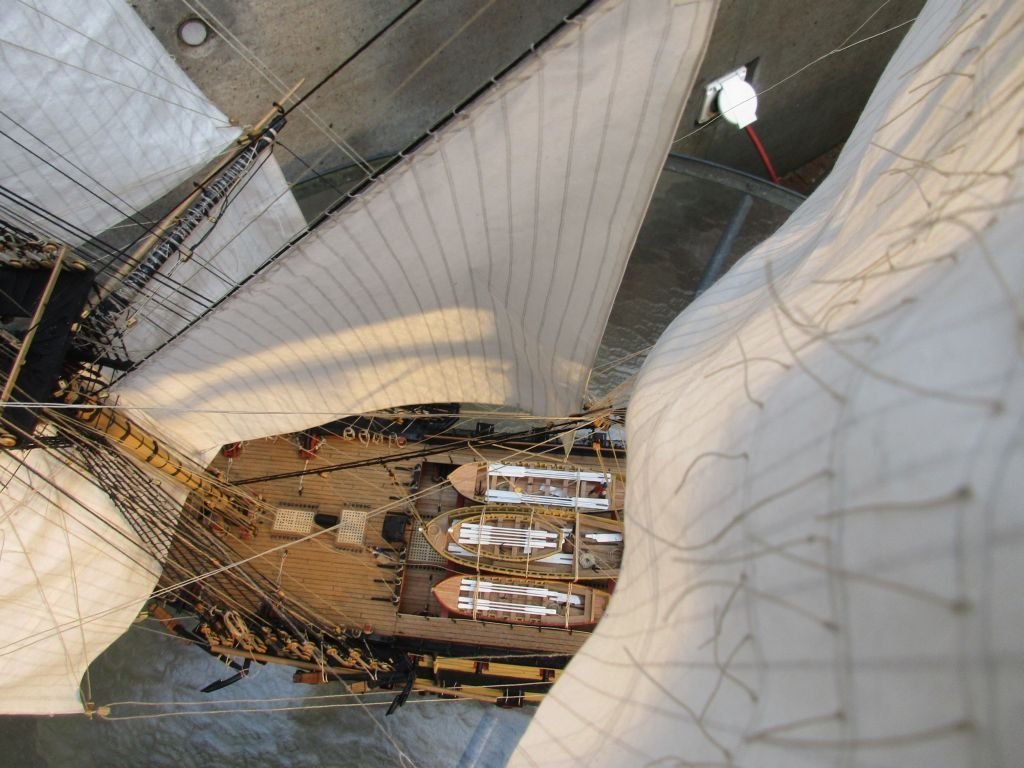
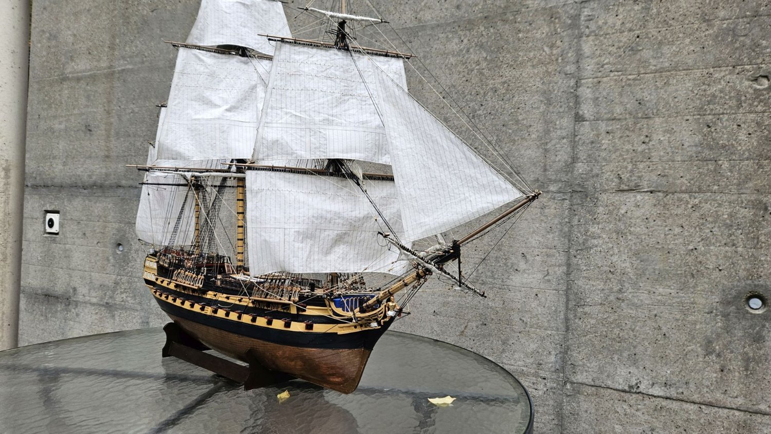
all sails are now installed
-
Brian Lavery in 'The Arming and Fitting of English Ships of War' also writes of using cuprous alloys. He doesn't say what kind of alloy exactly but he writes about the problems with the strength of bolts made from pure copper and the search for a suitable alloy almost as strong as iron.
Comparing different copper alloys I think the solution probably was some bronze - copper and tin - as it is the strongest. What the cost of such fittings was, is another question but losing a ship because of the decay of iron bolts was certainly costlier.
Peter
-
Hallo Franz
Your Barbara plan seems to me a really valuable discovery. Building her with the Pickle kit seems an excellent idea. If you like you could still name her Pickle and be probably closer to the real boat as Caldercraft or me.
By the way - I didn't suggest that Calcercraft was using the Adonis class plans but that I would use them to overwork their Pickle.
You could further consider a contemporary painting by Robert Dodd which probably depicts Pickle in the foreground on the right. There you see a vertically stepped foremast.
Looking forward to your build log!
Herzliche Grüsse
Peter
-
Allan's advice is of course good and sound - and you really are your own skipper and use the paint you like.
However to ensure a lasting joy of your build I would like you to consider something I also wrote in my present build log:
(In a book, written by a professional model railroad landscape builder he explains about colour scale. By that he means that if you look at a model in scale 1/100 from a distance of 50cm it should look the same as the prototype from a distance of 50m. And from that distance colours look less bright because of the air absorbing some of the intensity. He says that's the reason that models tend to look like toys if you use original colours. He recommends to always mix in a bit of white or grey and to avoid shiny colours.)
Following this advice I always mix about 15% of dull white into all paints, including black. And I use only dull colours. Some very nicely built models are in my opinion made to look like cheap toys, only because of the use of too bright and gaudy colours.
Peter
-
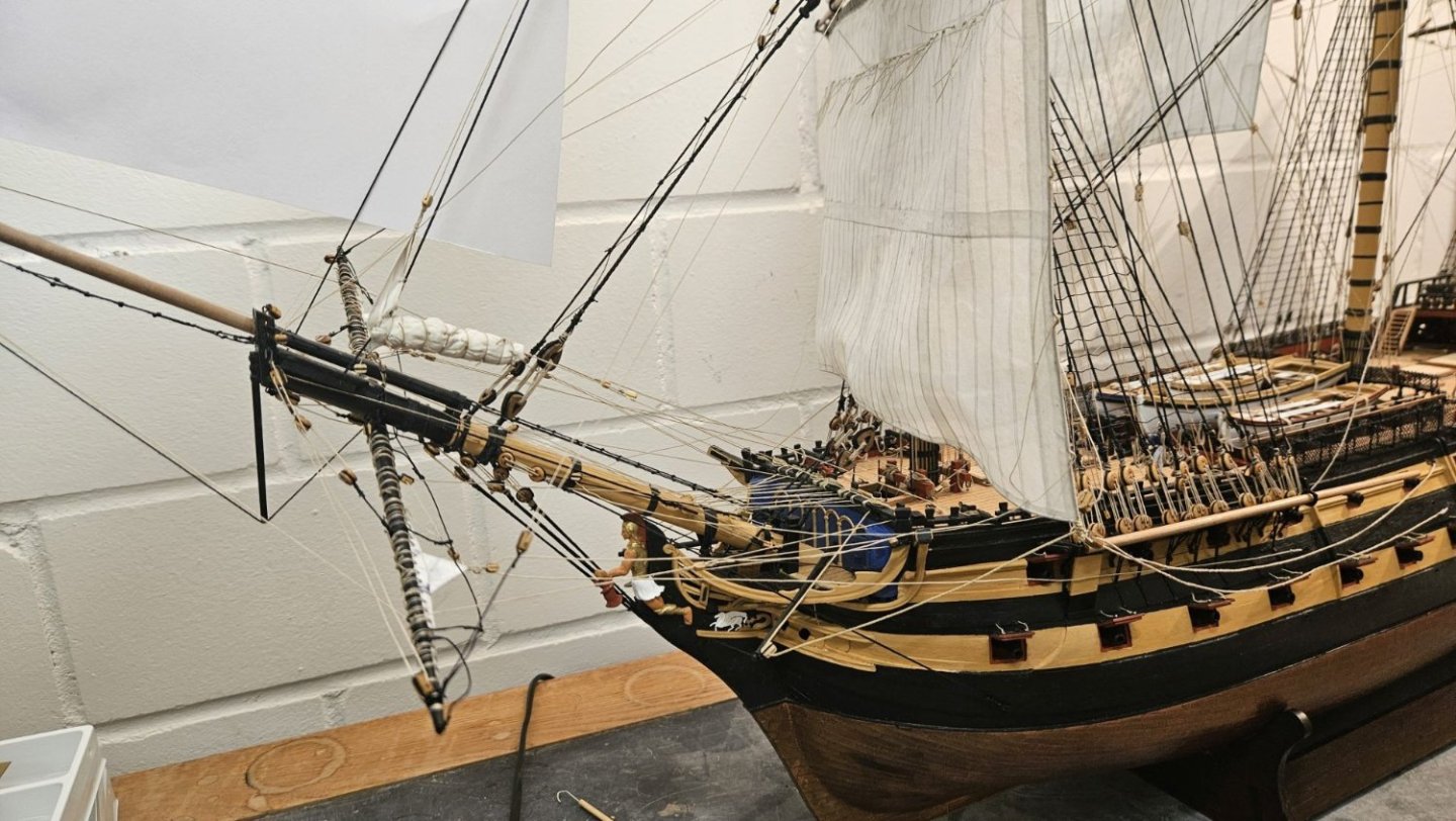
do kit designers dislike travelers? or
setting up the jib stay
Since I started making the sails I had problems with one of them: I simply didn't like the cut of that jib.
Although in the book Bellona of the AOTS series the jib looks similar or perhaps even stranger than that on the kits plans, all other sources showed quite differently cut jib sails. First I tried to reshape the sail more in accordance with Lees explanations. Very slowly I finally realized, that in the kit the jib sail was wrongly set on the fore topgallant stay and the jib stay completely omitted.
I guess sometime during the making of the bowsprit I was glad not to have to make a traveler for the jib stay assuming that on a 74 a different arrangement was used. Well, it wasn't.
Furthermore I think, I never met so far a kit with a decent traveler included. Perhaps there were some approximations like combining stay and out hauler and leading the stay directly through the hole in the jib boom which represents the sheave or setting up a simple ring around the bowsprit.
But after seeing how much thinking goes into representing beautiful, detailed stoves which are mostly invisible on the finished model a decent traveler shouldn't be asking too much for...
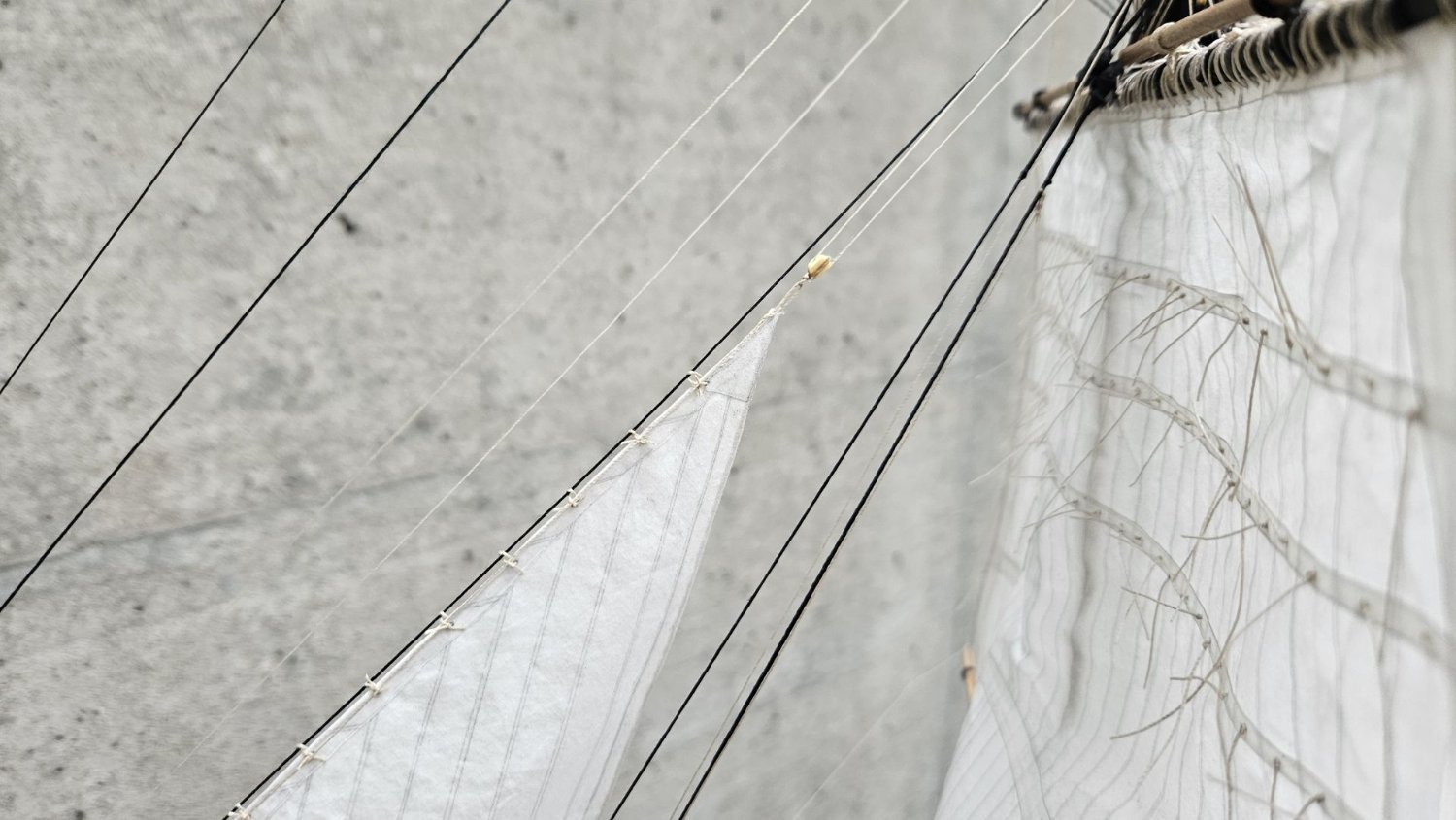
Fortunately the necessary cheek blocks on the fore topmast are included in the instructions. So, the difficulty was only to set up the traveler around the finished jib boom.
I searched some stiff brass wire with 0,7 and 0,4mm diameter in the leftover box and bent the 3 parts: ring around the bowsprit, shackle for the stay and hook for the tack of the sail. Owing to the reduced availability of material and my clumsiness the parts are rather a bit oversized.
Shackle and hook were finished with a bit of soft solder, threaded onto the opened ring, the whole forced onto the jib boom and the ring closed and soldered. While the jib boom was protected with some masking tape the whole arrangement was now painted. A small block was fixed to the ring for the down hauler.
As jib stay I fixed some 0,5mm black thread to the shackle, led it up and through the starboard cheek block on the fore topmast and down the fore channels. I set the end up with a simple tackle, hooked into a ringbolt on the channel. The out hauler is 0,5mm natural thread (slightly oversized again), leading through a hole in the outer end of the jib boom (this represents a sheave) and back towards the portside knighthead. Again it is made fast with a simple tackle, hooked into the lower part of that knighthead.
Now I made an adapted paper template to test the jib sail and found it looking definitely more convincing.
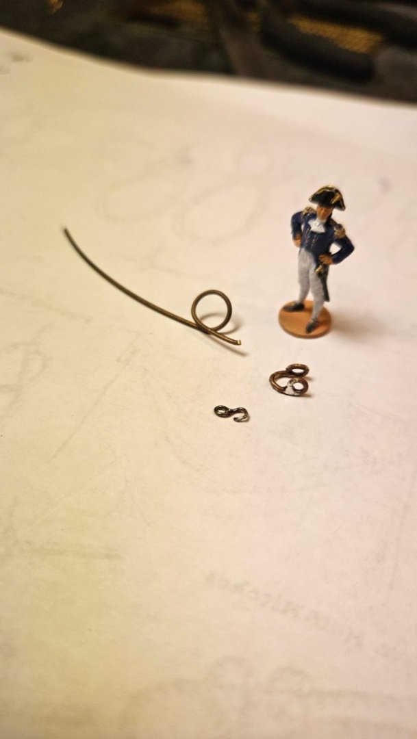
the skipper checks the parts of the traveler
the ring is not yet soldered
finished traveler in place
jib stay through the starboard cheek block

jib stay tackle inboard of the shrouds

in hauler set up with a tackle to the knighthead - its end is belayed in front of the skipper
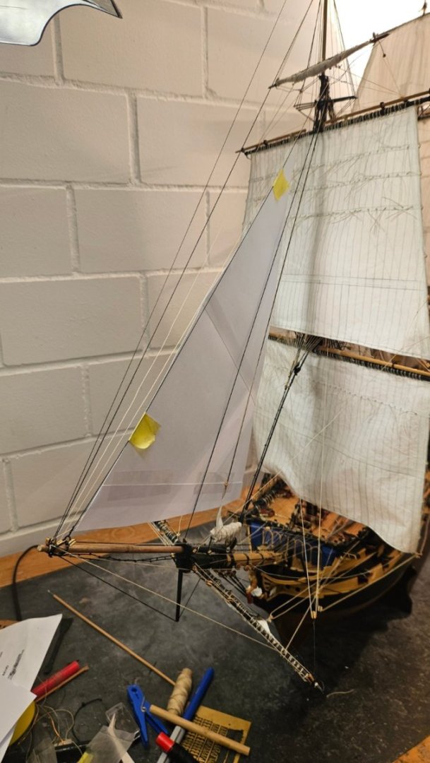
adapted jib sail template on the new jib stay
-
You should use the Victory Models plans only as a general guideline and check carefully with Lees. The plans are generally good but may have some disputable details.
There were also several changes in the rigging from Bellona to Vanguard - e.g. Bellona still had the lateen mizzen yard.
The Victory Models plans on the other hand show for example the topmast stays rigged below the associated preventer stays which is quite likely the wrong way around.
- GrandpaPhil, allanyed and mtaylor
-
3
-
fore topmast staysail
This as well is set furled. By reducing foot and leech each by 20%, I got a sail area of roughly 2/3 of that on the plan. The sail was again made in a simplified way and bent to the fore topmast stay.
Because I did earlier rig the preventer stay above the main stay I had to set the staysail on the stay itself. Perhaps thismeans, that the arrangement of the stays is in fact incorrect.
The sail was bent to the stay with robands and all lines were added.
While now furling the sail tried to follow the explanations of John Harland in 'Seamanship in the age of sails' - as well as I understood them. The outcome doesn't look to bad and after belaying the lines, I'm now ready to move on to the last sail, the jib.
plan with reduced sail area
sail set, not yet furled

...and furled
looking ok
-
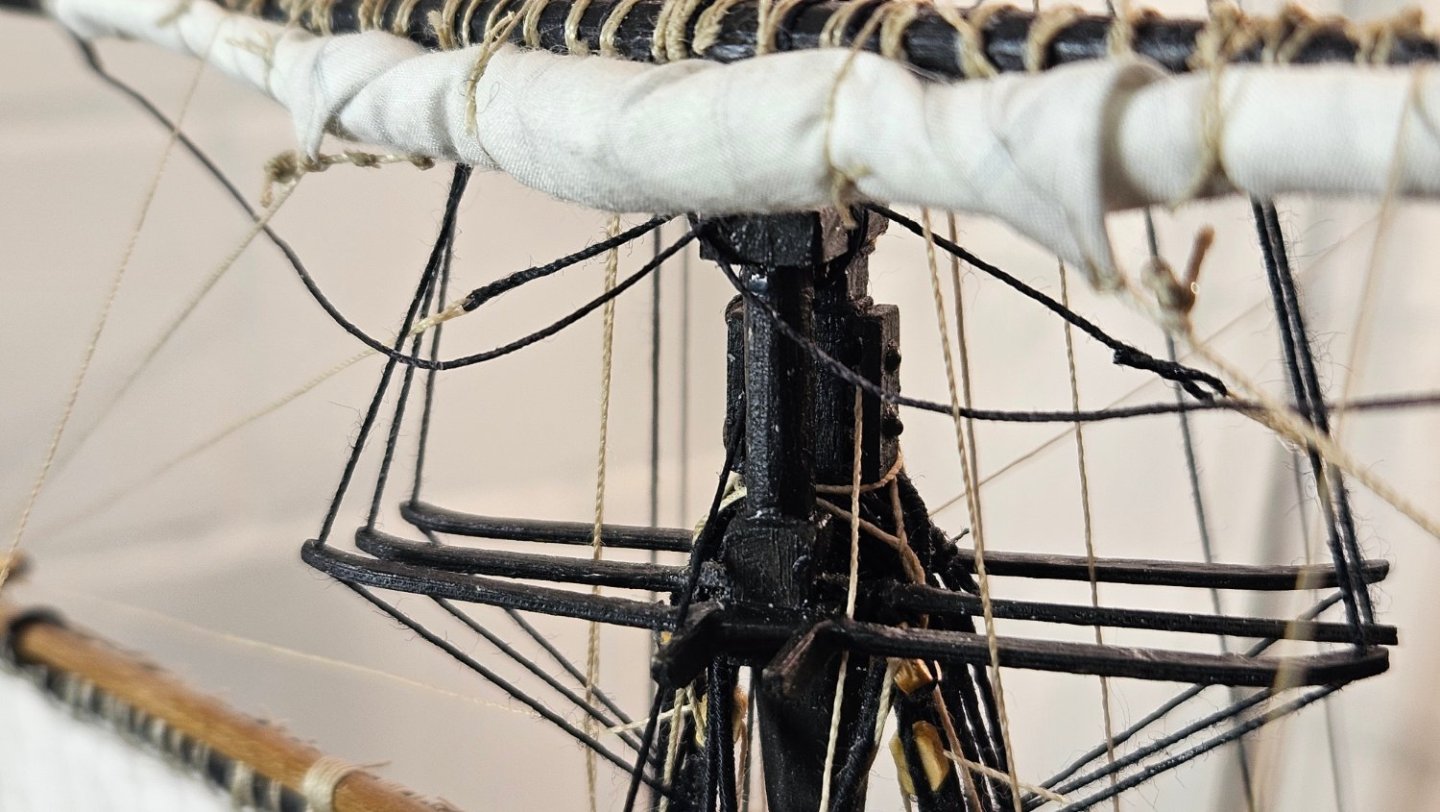
spritsail yard and sail
A by 30% reduced and furled spritsail was bent onto its yard. Without the spritsail topsail yard the rigging could be a bit simplified. On the other hand I did add the guys according to Lees' description. The yard was triced up by about 20°, as on the painting above.
I rather like the dynamic impression Bellerophon gives with this arrangement.

- DonSangria, KARAVOKIRIS, BenD and 14 others
-
13
-
 4
4


HM Cutter Alert by flyer - Vanguard Models - scale 1:64 - naval cutter
in - Kit build logs for subjects built from 1751 - 1800
Posted
Thank you and I will do my very best.
A visit to your Alert showed me what could be possible. Presently I do not plan to attach the friezes but will try to achieve the impression on the cover of AOTS Alert instead.
Making my own sails and adding a boat should nevertheless create a sufficiently sophisticated result.