MORE HANDBOOKS ARE ON THEIR WAY! We will let you know when they get here.
×


piratepete007
-
Posts
513 -
Joined
-
Last visited
Content Type
Profiles
Forums
Gallery
Events
Everything posted by piratepete007
-
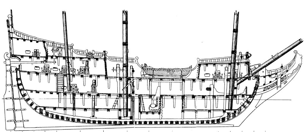
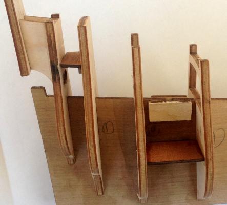
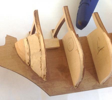
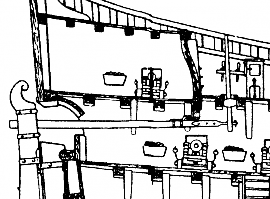
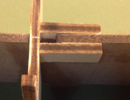
 With a long strip of wood placed longitudinally down the hull side, the frames were checked for alignment. I was pleasantly surprised that neither packing or reduction was necessary along the frame edges.The top edge (beams) contour of the frames supporting the deck was checked and I found that all were good except for Frame 7 which although it been seated in correctly in the keel and the bottom edge seemed to fit the contour of the other frames, I still needed to shave off approx. 1.2 mm. from the top edge. It was essential that there was a continuous supporting surface presented by all the beams when laying the deck as this ship is the only one without the usual Euromodel laser-cut plywood decks on which planking occurs. In this ship, all the decks are simply made from 2 x 4 mm. walnut strips. Nothing surprising so far. The following diagram shows some of the detail that can be found in the typical Euromodel drawings. There is ample material here for the person who wants a taste of scratch building. What is clearly evident is the Gun Battery which extends the full length of the ship and the Quarter Deck which of course is only partly visible. Nothing unusual - sure. However, Euromodel has engineered small plywood pieces to insert for these decks where it is necessary to support gun carriages. A simplification for sure but it does make the building easier (but does not prevent the ardent enthusiast in putting them in). There are three laser-cut plywood pieces supplied: 2 x ’15’ used either side between Frames 9 & 10 to form part of the Battery Gun Deck 1 x ’15 bis’ used between Frames 10 & 11 to accomodate two Quarter Deck guns. The Battery Deck pieces fitted tightly between the frames but the Quarter Deck piece was a loose fit and I had to use support strips underneath against Frame 11. Both pieces are shown in the photo.
-
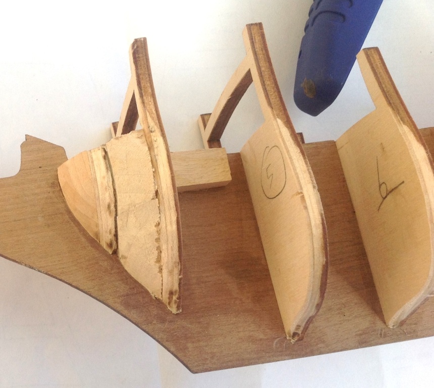
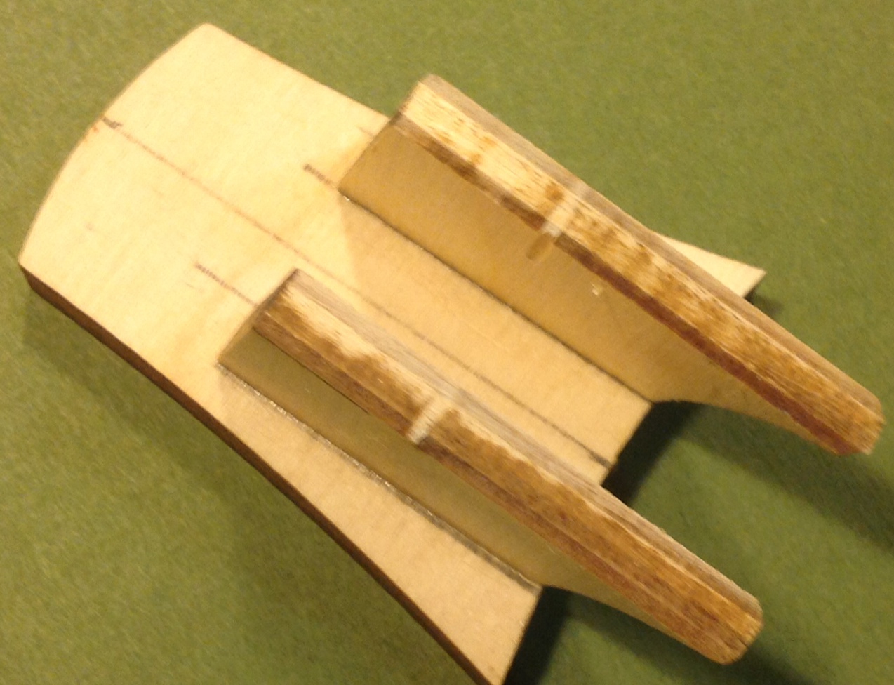
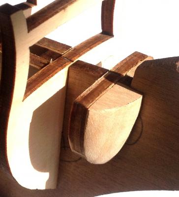
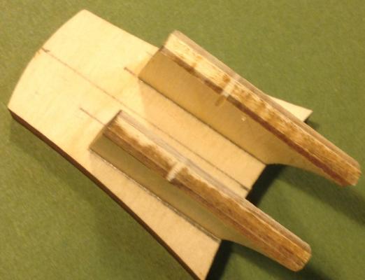
Using the supplied drawing templates, two bow filler blocks were shaped from the 10 x 20 x 80 mm. block supplied. I also inserted EXTRA filler blocks behind these (between Frames 3 & 4). Creating the curvature on these blocks then enabled me to continue the curvature over the original filler blocks forward of Frame 3.
-
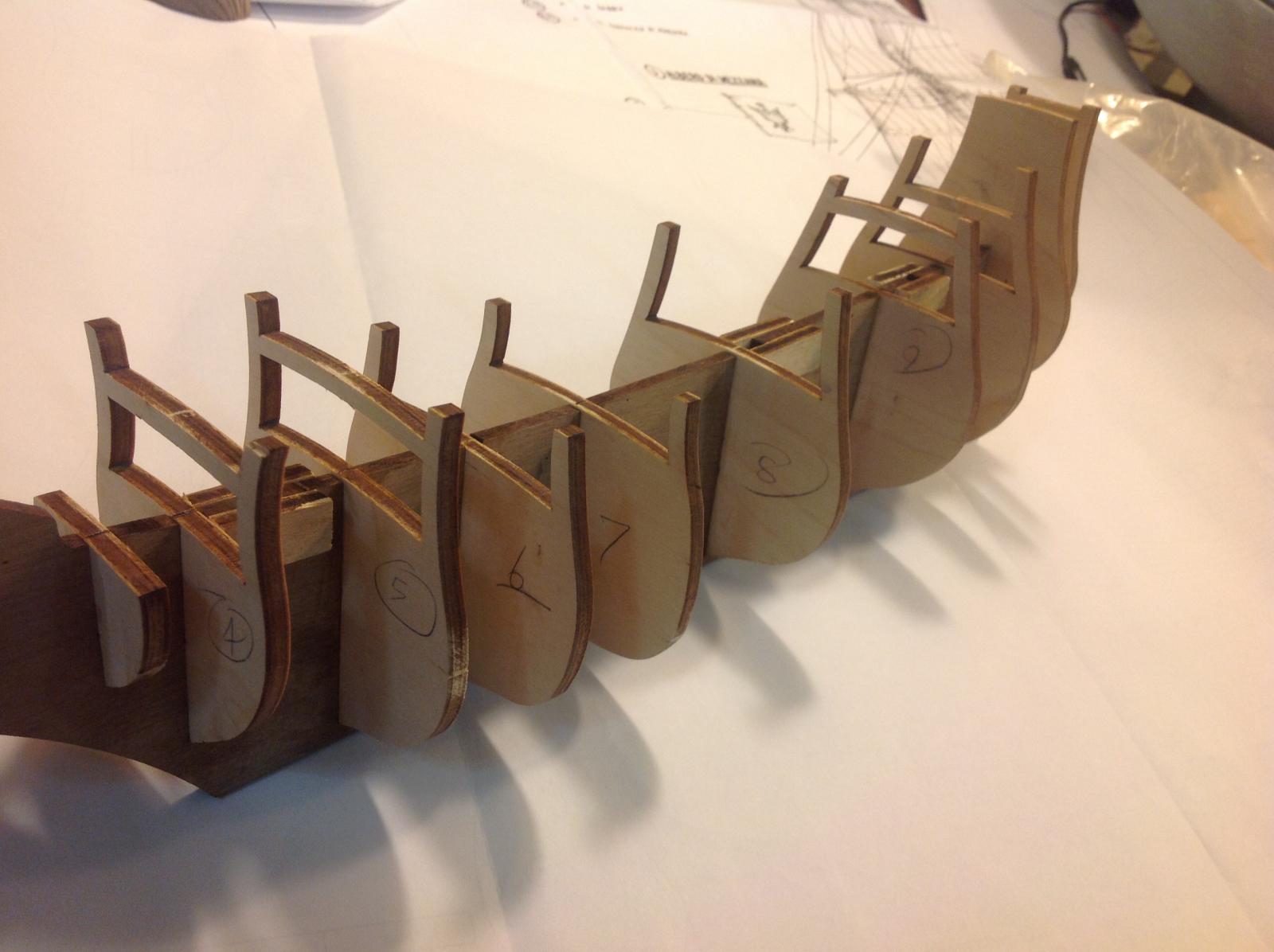
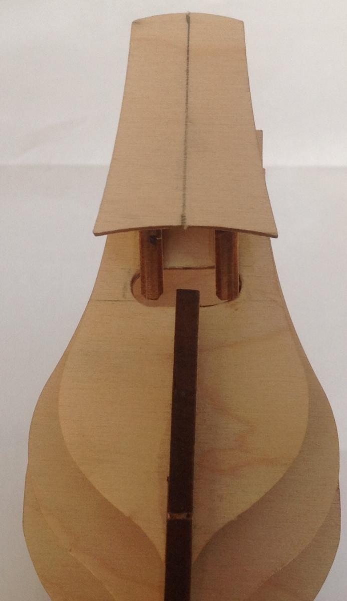
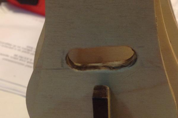
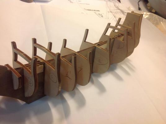
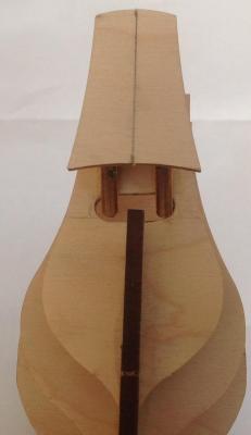
The Euromodel Defflinger is typical of their other models with high quality timber, accessories and detailed plans. OK, that's enough of the usual preamble ! The longitudinal keel is laser cut from quality 5 mm. walnut and slotted to accept the plywood bulkheads and to form the three mast steps. The laser-cut plywood is of marine quality - unaffected by water, uniform in thickness and excellent quality. Ten of the eleven transverse pre-cut ‘bulkheads’ were slotted into the keel as a dry run to determine which joints were too tight and which too loose. Frame 13 – the transom – was fitted afterwards. All the joints were extremely tight and a fair amount of sanding of the fitting surfaces was required. They were not fixed at this stage. This frame required a cut-out to be made and here is the first time in this build I needed to make a decision. The method of steerage requires a tiller arm to extend inwards from the rudder through Frame 12 into the hull. This then connects to a moveable upright whipstaff that allows steerage to occur. Since the tiller will not be seen, it could be omitted thus negating the need for a cutting through Piece 12. I chose to consider the possible linkage through rudder-tiller-whipstaff and so made the cut-out. The dimensions for the cut-out were not that critical – the drawing indicates approx. 30 mm. wide but in reality it is determined by the space between the transom supports, which is approx. 12 mm. In any case, I made it 30 mm. wide and It may be that the steerage system may not actually work but I was prepared to try it. The frames were glued in position using PVA glue. The main, fore and mizzen masts all have cut-out slots provided in the false keel. However, to hold the bottom of the masts in place, the mast steps had pieces of plywood glued either side of the slots to form a useful seat for the masts when inserted at a later stage. The two supports were glued in position onto the transom. The assembly was glued in position onto the stern side of Frame 12. To assist in the alignment/ positioning of this piece, a line was drawn to align with the keel beneath.
-
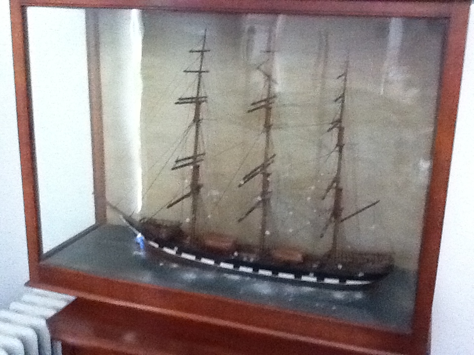
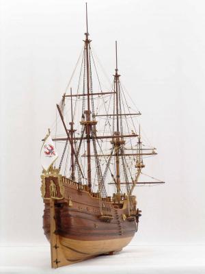
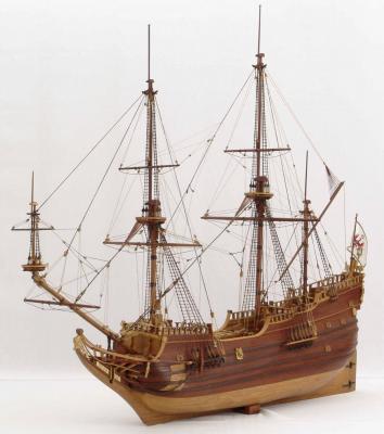
Well shipmates, this will be a very different post to the usual. Full of suggestions and alternative approaches. So hang on ! The Euromodel Derfflinger is a Dutch fluyt (pronounced 'flight') The fluyts are different to ships used in Europe in the seventeenth century with: a lowered quarter deck, and a pronounced round shaped-hull. Their dimensions were long and the long hulls had a very narrow cross-section compared to other square-sailed vessels. They were first produced in 1595 with square sails on their foremast and main mast and a lateen spanker on the mizzen mast. These vessels were requiring only a small crew to operate them and had the advantage of being cheap to build. Pieter J. Lioorne-Hoorn (Holland) is credited with their design with the first feluccas built in Lubecca, Germany in 1618. The last one was built around 1780. The ‘Friede’ felucca, as an example was built in Berlin in the dockyards of Berlin in 1682 – its length was 32 metres. ‘Derfflinger’ had two decks. Towards the bow was located the galley and areas for the storage of munitions, food and water. Below these areas was the stone ballast. Towards the stern, there were medium-size cannons and the compass. The forecastle generally contained four cannons, as did the stern area and quarter deck.

-
I have discovered a real gem. Euromodel have a 'fleet' of large ships that require a fair degree of skill and interpretation which I find challenging and 'just what the doctor ordered'. I unearthed a smaller ship of theirs which has largely gone un-noticed by most builders. It offers almost all the challenges presented by the larger ships, is much cheaper and allows the enthusiast contemplating some of the Euromodel ships as the Royal William or the Friederich Wilhelm zi Pferde a chance to quickly gain an insight into what the plans are all about. Its smaller size means that you can go through any constructional stage more quickly - right through the hull construction and up to the detailed sails. Anybody interested in seeing this post ? If so, the text and photos will be presented with many, many points being open-ended for you to make your own choices. A little different to what is normally posted. Pete
-
Hans - just an early piece of advice. Much has been said in other logs about how difficult it is to bend the metal castings provided. My experience with a number of Euromodel ships and the long metal stern gallery-type windows is that they come pre-curved and IF your build in this area is correct, then they require very little, if any, further bending/ curving ! That is the simple truth of the matter. I have recently finished fitting (but not fixing) the myriad of metal pieces on the Falmouth stern and they all went together like clockwork and I just sat back in amazement. I knew the pieces were going to fit and so was open to making small adjustments to the shape of timbers surrounding them. To achieve this, during the build I just kept measuring and re-measuring (and re-measuring) the various heights above the keel at the stern as well as taking into account the widths between decks. Not at all difficult but just time consuming. Plan Sheet 2 shows a longitudinal section from bow to stern but I had to keep reminding myself that this is for a scratch build so I had to take into account slight differences in deck thickness and various other nuances. It was just a matter of being totally in tune with the drawings. I think it is helpful to know that the pieces will/ do fit. Pete
-
Crackers - have you taken some photos of the finished sails on your Falmouth build ? Would love to see them finished and in place.
-
Richard, both kits extend your skills and both are begging for your own variations. Personally, out of the two, if I had to choose, then I would go for the Falmouth due to a number of factors. For example, the stern construction requires some interesting thinking (which I have written about) and the fact that it has a 'Sun Deck' for overhead protection whilst working in the tropics. Those two points make it a great project. It is distinctly different. But there again, that applies to all the Euromodel ships ..... Pete
-
Richard - there are two new updates for the Falmouth, one of which contains a considerable amount of stern detail. So have a look at the Euromodel website for FAL.INT.03.v3 (and FAL.INT.01.v4). Pete
-
Hans - there are updates for the Falmouth on the Euromodel website. I have put in a very thorough description of a major part of the stern build. Have a look at that update (FAL.INT.03.v3) as well as FAL.INT.01.v4. Good luck with yours. Pete
-
Just think about it Hans - problem solved for you but it involved Australia, Italy and Norway ! Those stringers should arrive shortly and that will be great. Pete
-
Nigel, my notes on the Euromodel website for the LaRenommee need some updating and adding to so I will be looking forward to your comments during the build - and any helpful criticism on what I have done so far. It is a beautiful and different ship, so enjoy. Pete
-
Hello Hans, fantastic that you are building this ship. I am currently working on this merchantman and will be following your efforts with great interest. There are never any problems with missing parts (rare that it is) being replaced. Pete
-
Ponto - great to read that you have purchased the Euromodel LeRenommee. I am currently working on the Euromodel Friederich Wilhelm zu Pferde (a German frigate) which is full of surprises and challenges and that is what you will experience with your French ship. This is the sleekest ship from their 'stable' and like all of their models, the challenges will be aplenty. I have posted construction notes for some of the hull construction on their website. Good luck. Pete
- 8 replies
-
- 1
-

-
- Euromodel
- Royal William
- (and 1 more)
-
Mathew, if you like to contact me via a PM, I can give you the lady's email address. Pete
-
DO YOU LIVE IN ADELAIDE, SOUTH AUSTRALIA ? ... if so, please read on. I have been approached by a lady who has a complete re-rigging of a ship and I do not have the time to do it. I believe she is more than happy to pay whatever it costs to do this task so if anybody out there can help, please, please,let me know. The ship is important to her and her brother and they come from a LONG line of sea-fearing captains. So, all in all, it sounds like a very interesting project. Pete
-
Tony - there are a few pieces of timber strips that are 760 mm. in length. My suggestion is that you get one of those postal cylinders/ tubes, put the lengths in there and carry on board as a separate piece of hand luggage. Alternatively, that length should fit inside a normal case ? Pete
-
I wish I was as good with words as you are Brian. That is what I have been trying to say all along. Pete
-
Amfibius - you have raised a number of points in your recent posting and as always, great for discussions. I guess we can pick out little points in kits from all manufacturers. I would be saddened if this forum turned into a kit 'bashing' rather than the sharing of ideas and concerns. The notes are useful and I know you have been reading them but you have to have the kit in your hands to appreciate it. I will pass on the concerns that I read to Euromodel - but I am not on their payroll. The beakhead at the bow supporting the head rails is laser cut so not sure what was intended there. Were you referring to the quarter galleries at the stern ? If so, as you build the ship, you would find that laser cutting would be of little use in a 3D carving. Regarding the price factor, I spoke to Euromodel a few minutes ago and this is an unfortunate aspect of market pricing out of the hands of Euromodel. The prices are highly inflated making other brands more attractive but there is an attractive option - purchase direct from them from their on-line shop. I did this and it was a seamless exercise. They also tell me that they will have a phenomenal sale in mid-March. Brian C - what was supplied for the deck planking of the Royal William was good quality walnut but I chose to use Tanganyika which is a much lighter timber ... and so we go on. Puckotred - I guess this is where the MSW is valuable because concerns by individuals can grow out of all proportion. Have a look at the stern of the Euromodel Pinco Genovese. The kit does include metal decorations. Pete

-
Fair comment Brian but almost a contradiction of sorts. Euromodel kits have always been seen as more than a standard kit build (I have always thought of them as 'quasi scratch' builds). It is for that very reason I began writing these files as I realized there was a gap out there for kit builders wanting to build a Euromodel ship. I thank you for describing my notes as 'excellent' although I often revisit them to re-write them ! In the light of these notes, then, I agree prospective builders need some experience (not really half a dozen builds as you suggest) but it is my hope that the notes will guide people through the necessary steps. I have done/ are doing the necessary interpretations of the drawings and have recorded my results for all to see. That must make it easier. Pete
-
Phew .... sanity prevails. Thanks Nigel Pete
-
If you guys are interested, go to the Euromodel website homepage, look at the files under "Customer Assistance' or even better, once you have looked at that, download their free app 'FreeReady, and automatically receive any new updates which I post - they generally occur every two to three weeks covering many ships. Pete
-
Thanks Jean-Pierre. We are on the same wavelength about anchors but in the light of a thorough amount of commentary over the last 24 hours, what more can be said ?. In the end, it comes down to the degree of excellence shown by any one builder. Some are more excellent than others ! The more excellent the builder, like yourself, the more that person will question. I come back to the point that at least Euromodel in their drawings not only show the anchors but include actual dimensions. I think that that is the critical point. Appreciate seeing the evidence in those photos ! Pete PS Maybe somebody can start up a new post because as Nigel said, the original topic for this thread has been well and truly covered ?
-
Amfibius - downloading my pdf's onto a tablet, reading in bed and dreaming about ships - you do have a problem (just joking !). I see Euromodel have a free app called FeedReady which will notify you of any updates that I have posted, so that should keep you going ! That horseman on the transom is one little challenge as you will have seen. Do you draw the figure and paint it in or do you carve it in 3D like I did ? That is the beauty of Euromodel ships which keep presenting alternative approaches. So it will be with the windows and lanterns and as you say, brass strips etc would be useful for the lanterns. Not something I have tried to do as yet. Happy dreaming Pete PS apologies for any flippancy !