
MORE HANDBOOKS ARE ON THEIR WAY! We will let you know when they get here.
×


piratepete007
-
Posts
513 -
Joined
-
Last visited
Content Type
Profiles
Forums
Gallery
Events
Everything posted by piratepete007
-

RIGGING THE ROYAL WILLIAM
piratepete007 replied to piratepete007's topic in Masting, rigging and sails
jbshan - thanks for your comment. R.C. Anderson's book title is .... ? Pete -
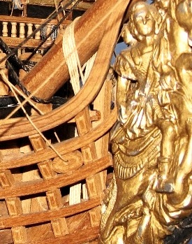
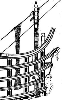
Vince - I agree with Greg - your ship, your way. There are so many 'twists and turns' to make with the rails (pardon the pun) that small differences will influence the outcome greatly. However, your build is rich in detail and interpretation and that is what it is all about. I am including a photo and a diagram for everybody's interest just to show how variations do creep in. In hindsight we are all very wise. Spot the differences and yes it is the same ship ! Pete
- 593 replies
-
- 2
-

-
- royal william
- euromodels
- (and 1 more)
-
RIGGING THE ROYAL WILLIAM
piratepete007 replied to piratepete007's topic in Masting, rigging and sails
Whow, JerseyCity Frankie - that lengthy explanation is so much appreciated and sounds logical even if I have to read it through a number of times to fully comprehend it. Thanks for the time taken to explain it to me - and others. Any chance of pointing me to a diagram to cover what you said ? Pete -
RIGGING THE ROYAL WILLIAM
piratepete007 replied to piratepete007's topic in Masting, rigging and sails
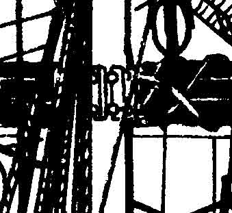
Mark - you could be correct since I have enlarged that portion of the drawing by about 400%; sensible suggestion because it is just so odd. Pete -
RIGGING THE ROYAL WILLIAM
piratepete007 replied to piratepete007's topic in Masting, rigging and sails
Mark - it sures does but it appears on both the Foremast and the Main Mast. Not too good on the guitar but guess I will continue to play my own song !!! Suspect it must be some sort of tensioning block ??? Pete -
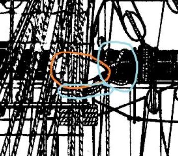
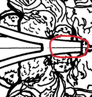
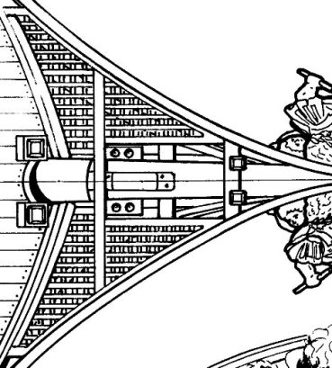
With my limited knowledge of rigging, I am seeking some help/ guidance on the rigging of the Main Mast of the Royal William. The drawing for the total ship contains so much detail but here goes. I am gathering together a mass of general detail to put into a 'Resource File' that will be available to all. The topsail yard is attached via what I would call a normal parrel (some spell it parral) and I am OK with that. It can be easily seen in one of the attached drawings. These were in use until the late 18C. In the early 19C, iron parrels came into use. The main yard from the drawing appears to be attached with a truss pendant ? (shown in blue) but there is an odd-shaped 'something' (shown in orange). Can anybody throw light on what this shaped 'thingy' might be ? Thanks for reading this and your possible help. Pete
-
Just doing a little 'surfing' for rigging and came across this post. The bowsprit saddle was the supporting piece that sat between the bowsprit mast and the jibboom but the piece described as 'croissant de beaupre' or the 'bowsprit saddle' in the posting above is incorrect. That often somewhat semi-circular piece is a fairlead designed to stop lateral movement of ropes and also giving an advantage to seamen having to haul vertical ropes. Such ropes passing down the bowsprit and through the fairlead were then behaving as near-horizontal ropes allowing more seamen to haul on the rope. Pete
-
Frank, If I can answer for Mark - the bending of the stern you refer to - this laser-cut transom piece is made from good quality 3 mm,.plywood over which various metal ornamentation pieces are added so it simply forms a base surface. Naturally, it comes in a flat form in the kit but for convenience of use, it is soaked in water for a while and then bent and dried over some suitable surface to create a curve. By their very nature, Euromodel kits actually encourage builders to modify - if they wish to - and so in the build logs on MSW many variations are seen from various very enthusiastic builders. The question, then, of accuracy comes down to the degree of modification carried out. The more the personal interpretation, the more work there is in modifying various parts. On the other hand, the build can be kept relatively simple with virtually no modification - but this is never seen on MSW. Pete
- 652 replies
-
- 5
-
-
- royal william
- euromodel
- (and 1 more)
-
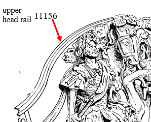
Keith, Vince, Mark - mystery piece 11155 for the RW is not a mystery. It is the final extension of the top head rail at the bow. The side view and top views show this. Depending how your build goes, it might be included, thinned down or omitted. Pete
- 593 replies
-
- 6
-
-
- royal william
- euromodels
- (and 1 more)
-
Mark, I am on the track of that one but everything except my computer is packed away for a shift a few thousand kilometres away - plans, ships, parts, everything !! Its got me tricked temporarily but I WILL get the answer. Pete
- 593 replies
-
- 1
-
-
- royal william
- euromodels
- (and 1 more)
-
Mark, looking at your planking over of the plywood transom, the vertical placement of the planks is more logical than my horizontal ones. Why didn't I think that one through like you did ? Ouch ! Pete
- 652 replies
-
- 1
-
-
- royal william
- euromodel
- (and 1 more)
-
Actually, Kevin and others, the Euromodel kits uniquely allow you to work at many different levels of difficulty. What you are seeing on MSW are some very skilled builders - like KeithW - who are 'pushing the boundaries' and thoroughly enjoying what they do. So what is presented is not the standard level of build. Their work in milling out the windows is a high skill level BUT many, many completed Euromodel ships (and others) simply have the solid window panes painted over. It does not have to be complicated ! Have a look at the Euromodel photo gallery and you will see what I mean - every ship is shown there in quite some detail. I don't think any of those displayed models have their windows milled out. There are just so many things you could do to enhance these models. While on their site, notice they are having a really big discount on all their models. Pete
- 593 replies
-
- 4
-
-
- royal william
- euromodels
- (and 1 more)
-
Vince, pretty difficult to assess the position of your top rail from the photos above but I thought I would throw in the attached photo which could/ should serve as a guide to the top rail/ grate positioning. The photo does not clearly show the fact that the grate frame is almost totally above the top rail mid-way along. The drawings in side view do not show any of that frame - it seems to me that some will be visible however the rail is curved. In the end, you have to go with what you produce. I have a large data bank of photos to assist in your interpretation of this ship, so if there is any hiccup, send me a PM and I could send a few photos. Pete

- 593 replies
-
- 5
-
-
- royal william
- euromodels
- (and 1 more)
-
Vince, you have experienced that 'Euromodel challenge' in producing those rails - and what a great job you have done. This is what sets Euromodel 'kits' apart from so many others. The opportunity to put your own interpretation into the build and not having to do everything in a lock-step method... and this is what you are doing. Interestingly, I had to assist a person from Sydney through his Euromodel build - which he completed; he then thought that was enough of Euromodel, went on to another manufacturer and a standard kit, got bored with it and went back and bought another Euromodel 'kit'. He missed that unique challenge ! That is why I, and many others, are following your build with great interest. We like to see how your own individual approach evolves. Keep at it and keep posting. Pete
- 593 replies
-
- 2
-
-
- royal william
- euromodels
- (and 1 more)
-
So now I am wondering if the treenailing I see on some models is overdone - says he who has never done treenailing. That's not a criticism, just trying to rationalize things. Pete
-
Not sure where this comment will finish up ..... I am reading an article by William Layman 'Precursor to an Expose on Forest Trees' [January 1, 1813] and archived by Google. The article deals with the strengths and weaknesses of timbers and how so much of it was sourced from a number of European and Asian countries including Russia, Germany and India. Fascinating enlightenment to me. There are some amazing references there from the 16C - 18C and beyond. William Layman was a Fleet Admiral and he is addressing his concerns about supporting the Navy ship-building industry to his Royal Highness William Duke of Clarence. Sort of a 'straight from the horse's mouth' commentary. What caught my eye was a short paragraph (on page 19) about treenails ' Tree Nails'. To quote verbatim .... 'The use of tree nails in the ship-building not only consumes the very best oak in the making, - but very much diminishes the strength of the timbers transversely cutting the ligneous fibres in boring; and they are, after all, fastenings. On the same principle, any fastenings which require the timbers to be so perforated are objectionable.' Anybody like to make a comment about this ? I thought treenailing was the common method of fixing ? Is he just making a point about the obvious ? Pete PS An article worth reading
-
Looked at the Micro-Mark catalogue - the bender looks like a little beauty. It handles widths up to 2 1/4 inches (57 mm.) and thicknesses up to 1/8 inch (or 3 mm.). Pete
- 593 replies
-
- 1
-
-
- royal william
- euromodels
- (and 1 more)
-
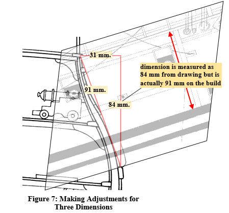
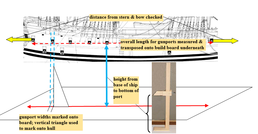
Hello All, Generally I sit in the background watching all these builds of the Royal William with a myriad of variations which are always fascinating. I admire each and every one of them and enjoy the solving of the problems that these variations create. These builds have moved away from the basic kit build - but that so easily happens ! There is an 'invitation' hidden somewhere that invites these changes. In the meantime, I am making changes to my files as a result of what I see on MSW. I feel moved to make a comment on one basic point - gun port positioning. The positioning of ports on the gun and main decks is already pre-determined by the supporting blocks but it is the upper ports that need careful alignment so that they fit in with the metal ornamentation. Also the port adjacent to the transom side gallery needs to be cut out after the transom is completed. In simplistic terms, the gun carriages - already constructed - mounted on the deck surfaces will themselves determine the height of the port. It is the longitudinal positioning that becomes critical to match in with the metal ornamentation. The problem will always be that some builders take their measurements directly off the drawings which is TOTALLY INCORRECT. The problem comes about due to the inward curvature of the hull that creates a larger measurement than the drawing indicates. The first diagram below (from the Euromodel Resource File for the Falmouth) illustrates this point by comparing a vertically arranged drawing with the actual ship behind it. The second diagram (thanks to advice from Nigel) illustrates a useful method for determining port positions. Here a vertical marker is used to determine the actual height above the keel, taking the measurements off a vertically arranged drawing. If this does not make sense, send me a PM to save room on Keith's post . Pete
-
Just a 'one-liner" but had to put it somewhere .... looking at the cramped height conditions surrounding the Main Deck capstan on the Royal William and thought it had to be a mistake .... the drawings showing only 1600 mm. height from deck surface to underside of Quarter Deck above ? Did some research and found military records of the time showing the average height of males during this era .... and guess what ? It was only 1600 mm or 63 inches. So 1600 mm. is a passable height after all (maybe as long as you kept your head down a bit !) Gee, the average height of males has increased over the years !! Pete
- 652 replies
-
- 3
-
-
- royal william
- euromodel
- (and 1 more)
-
Mark, Hope this makes sense ... the rudder blade typically had bearding (i.e. short sections of timber added along the forward edge between the pintles). This is not shown in the drawings for the Royal William. What I think most people do is to cut notches into the supplied blade.
- 652 replies
-
- 1
-
-
- royal william
- euromodel
- (and 1 more)
-
After almost eight years, I am revisiting my interpretive notes on the Euromodel Royal William and starting to re-write much of it by visiting every post on the MSW for this ship. I hope to include some notes but mainly photos from other builds to include so that others can get an immediate overview of different approaches made by different builders. It is a very humbling experience indeed from what I have seen so far. So in the near future, that will be re-posted back onto the Euromodel web site. I will be approaching the individual 'postees' to ask their permission ! This ship is a mighty ship because it caters for the individual who wants to make their own interpretation in their build. It just seems to throw that idea straight at the builder. Pete
- 652 replies
-
- 4
-
-
- royal william
- euromodel
- (and 1 more)
-
Now here is a philosophical comment which might just make things a little easier or maybe more difficult. It may be a little cavalier of me to say so but whilst the drawings from Euromodel are accurate and historically correct, I have been wondering of late whether I should or need to be absolutely precise to a fraction of a millimeter. When all the stern ornamentation is in place and the second planking is there, the positioning of the wale could well be a little subjective ! How come ? Well, we are looking at a three-dimensional model that is accurately portrayed in a two dimensional drawing. No question on that. Reality is that say, 45 mm. measured vertically off the plan could easily be 49 mm. when measured on the hull surface since the hull curves inwards. The purists will throw their hands up in the air but the most simple approach is to eye-ball the plans(along with measuring) and produce a 'best fit' for the wale positioning. My point is that in the past I have been critical of those who do not have the wale exactly butting up against a certain point on the stern metal castings. Is there room allowed in our thinking to tolerate small discrepancies ? After all this is a quasi-scratch build anyway. So look at the various photos in the Photogallery for the Royal William on the Euromodel website and compare what you see against what is in the drawings. Many small variations will be noticed. In summary, the important thing with the wales is that they follow the line of second planking (as they would have done historically) and that the stern ornamentation inclination follow the lines of the wales. If the conjunction of the wales and metal pieces varies a little, maybe this is not a big issue ??? It depends on what you want to achieve but what I am saying is maybe we should be prepared to exercise a degree of your own interpretation. I have yet to see two identical Royal William ships. So much for a little bit of raving on my part. Pete
- 652 replies
-
- 5
-
-
- royal william
- euromodel
- (and 1 more)
-
Keith - my notes are already amended and also include a few of Mark's photos (with permission). By soaking those wales in dilute ammonia (cloudy ammonia in supermarkets) for a minimum of seven days, they become so pliable that clamping them down onto the first planking until dry works a treat. Of course you guys would know about the use of ammonia but maybe some others who read this may find that useful to know. The only problem of adding those reformed wale strips on after the second planking is that historically they would then project out from the hull surface a little too much - but lets not get too pedantic. Pete
- 652 replies
-
- 2
-
-
- royal william
- euromodel
- (and 1 more)
-
Mark - all seems to be going well so far. I like the addition of the small strips to ensure correct transom supporting block angle. As I sit here in the background, I just wish I had the availability of all these RW posts when I did mine. These postings in fact are encouraging me to go back and do some savage re-writing of my original notes !!! One thing I am reconsidering is to actually bend the wales into the 'final' shape over the first planking in what I consider would be their approximate position. After drying, they would be removed. That way the major forming is done. When the second planking and stern ornamentation is completed, the wales can be added - I think - without too much extra trouble. Just a thought and would appreciate a few comments without hi-jacking your post. Pete
- 652 replies
-
- 3
-
-
- royal william
- euromodel
- (and 1 more)
-
Euromodel were more than happy to replace those incorrect pieces but Mark - to his credit - substituted his own. He is to be commended for taking this approach; many others would not ! I think the essence of problem solving is good communication and Mark and I did that through a series of PM's. Pete
- 652 replies
-
- 2
-
-
- royal william
- euromodel
- (and 1 more)