HOLIDAY DONATION DRIVE - SUPPORT MSW - DO YOUR PART TO KEEP THIS GREAT FORUM GOING! (Only 13 donations so far - C'mon guys!)
×

Erebus and Terror
-
Posts
410 -
Joined
-
Last visited
Content Type
Profiles
Forums
Gallery
Events
Everything posted by Erebus and Terror
-
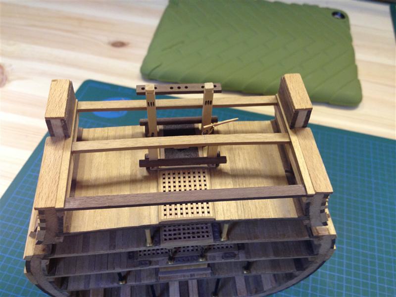
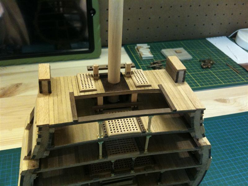
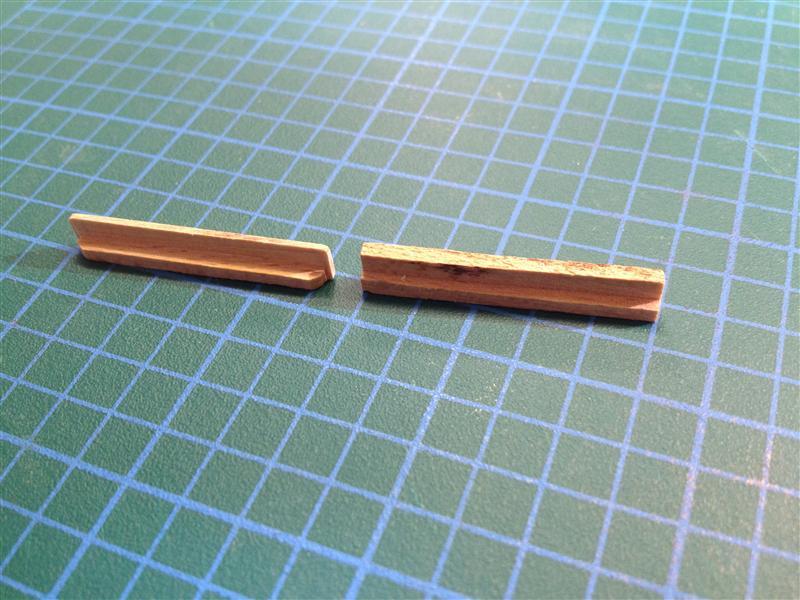
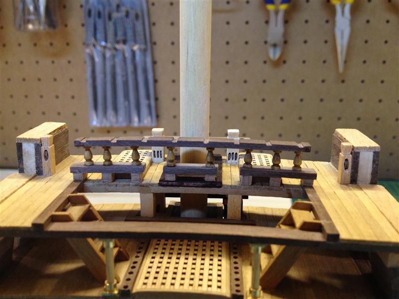
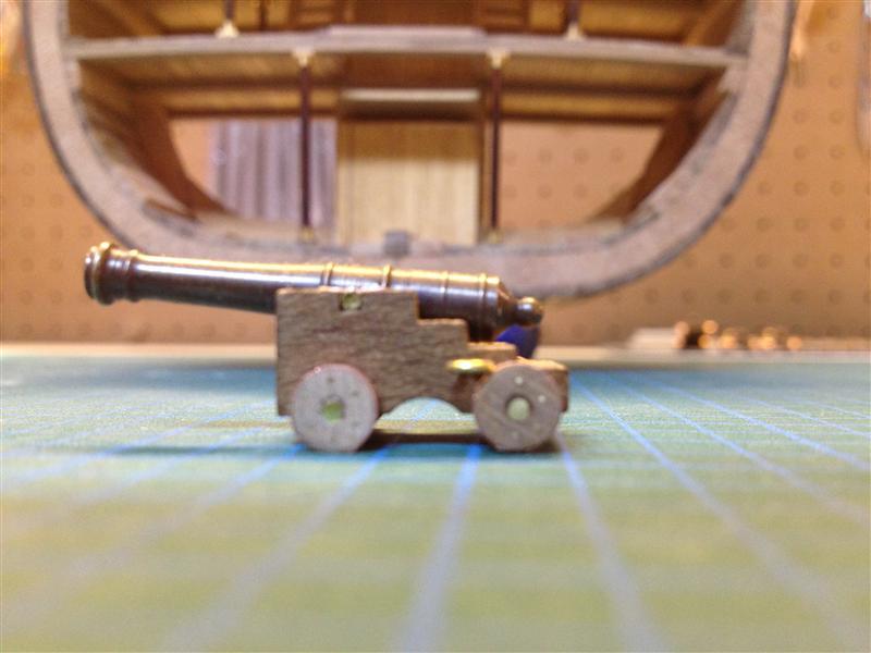
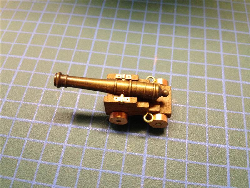
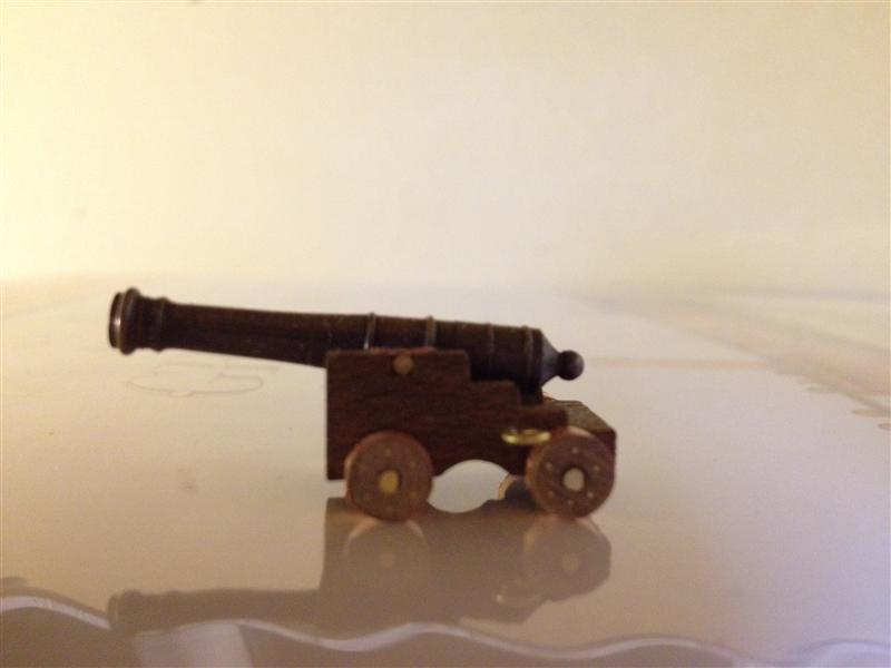
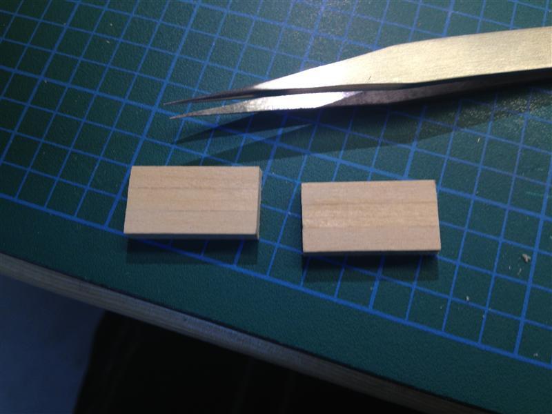
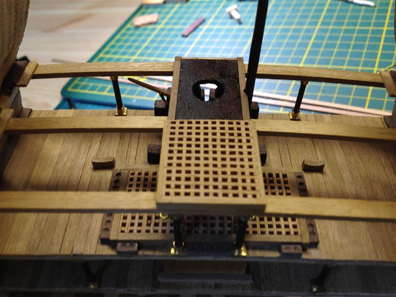
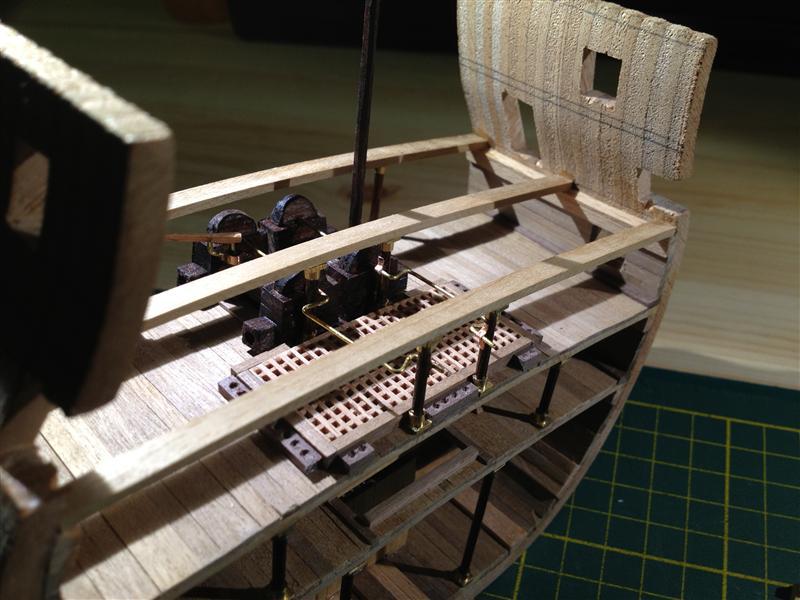
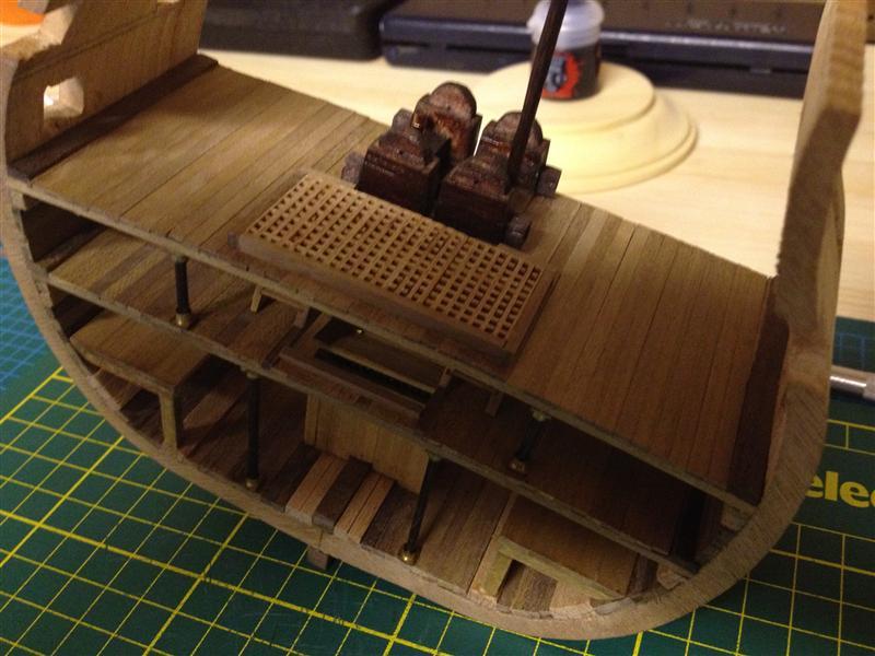
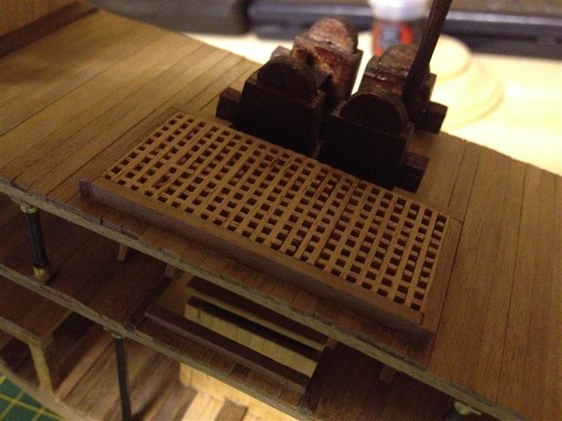
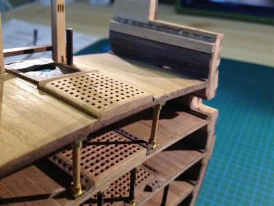
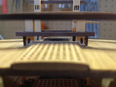
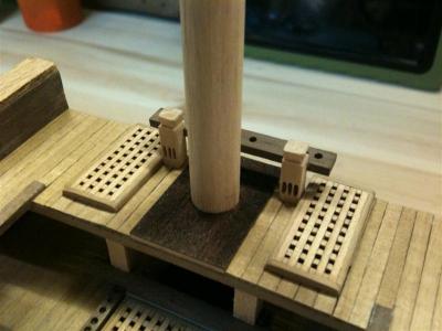
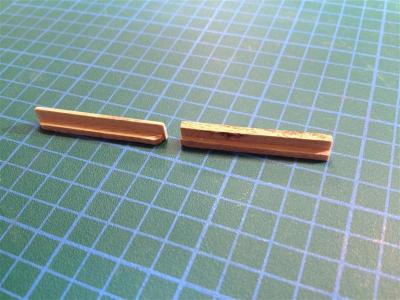
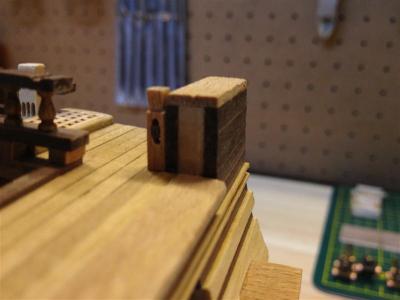
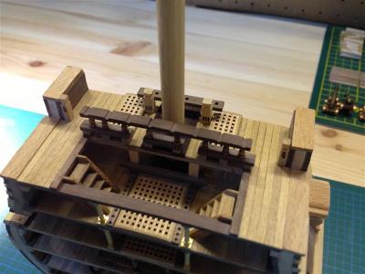
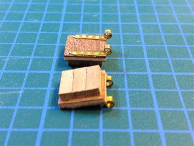
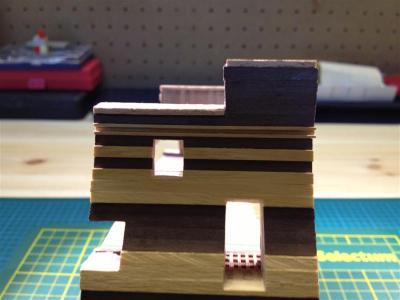
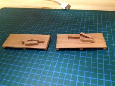
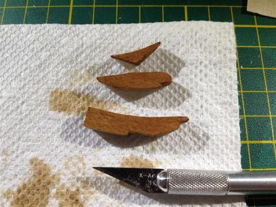
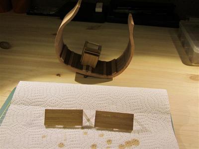
 It’s been some time since my last post, but that doesn’t mean I haven’t been working on my Victory. I’m fairly happy with the progress to date; as I proceed I’ve been trying to refine my technique following the example of the great craftsmen and craftswomen on this forum. Most of my recent work has been on the upper gun deck and the quarter deck surrounding the main mast. In this photo the grating for the hatchway has been installed on the upper gun deck, this time with a proper camber! Topsail sheet bitts (scratch built, not included in the kit). The scratch built jeer bitts were installed with the middle gun deck. Port elm tree pump (scratch built, not included in the kit). The quarterdeck beams are shown here as well. The framing in the kit isn’t accurate and it’s one of the aspects of the kit I haven’t tried to fix, given that it would require too much extra walnut board. In this photo the quarterdeck planking and gratings have been installed. Here I’ve attempted to simulate caulking by rubbing the edges of the plank with a charcoal pencil. It certainly looks better than the lower decks, but I’m still not 100% satisfied. On my next model I’ll try a different technique, I think. The port kevel block (scratch built, not included in the kit). The extended bulwarks are scratch built as well. Surprisingly, they aren’t part of the kit (see my previous post). Ladders from the quarter deck to the upper gun deck as well as the rail with slots for the hammock cranes. I’ve been working on the cannons for some time. Some of the iron work here has been done in copper, with brass wire inserts for the truck bolts. I know that the victory trucks weren’t clad, but on my victory they are (a little aesthetic license on my part). Currently I’m working on the steps. Corel provides a laser cut “L” shaped board for these, but they don’t look realistic when modified as per the Corel plans. I’ve extensively modified each by filing and sanding them down for a more accurate look. I have to admit that this has been the most tedious part of the build to date, but I think the effect justifies the effort. In the photo the “L” cut board is on the right, and my modifications are on the left. Finally, here are the gun port lids ready for installation.


- 42 replies
-
- 1
-

-
- cross-section
- corel
- (and 2 more)
-
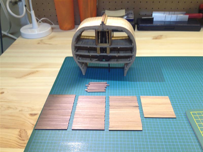
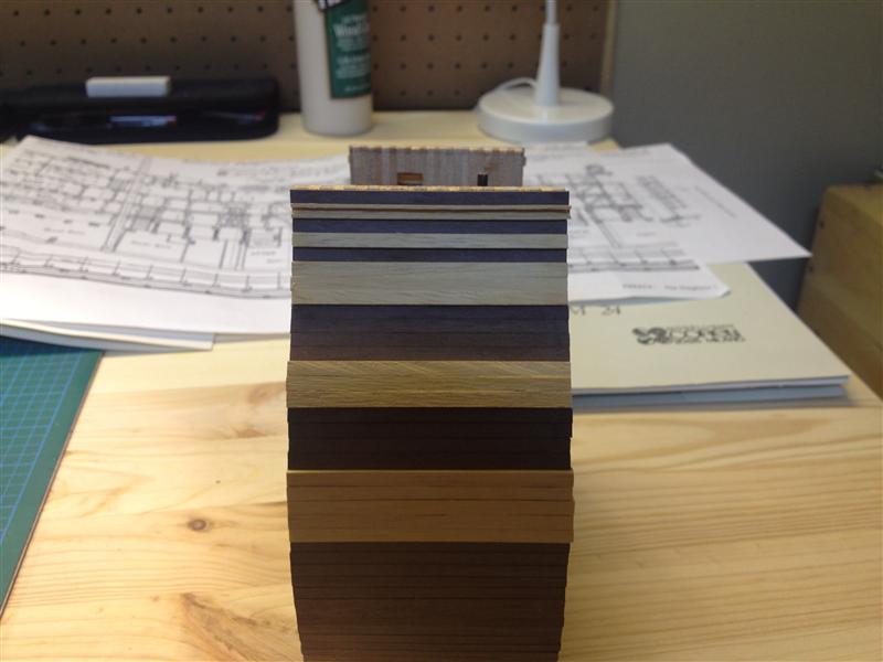
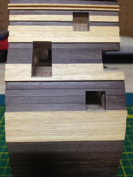
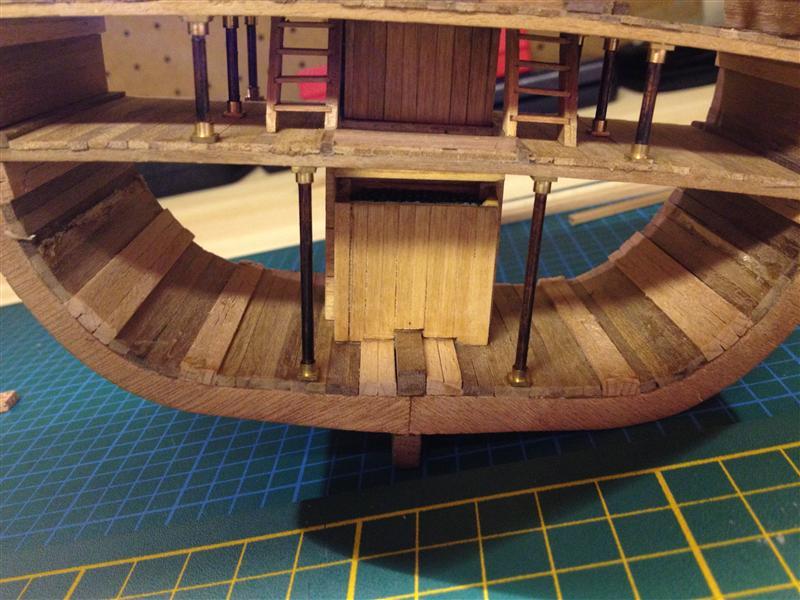
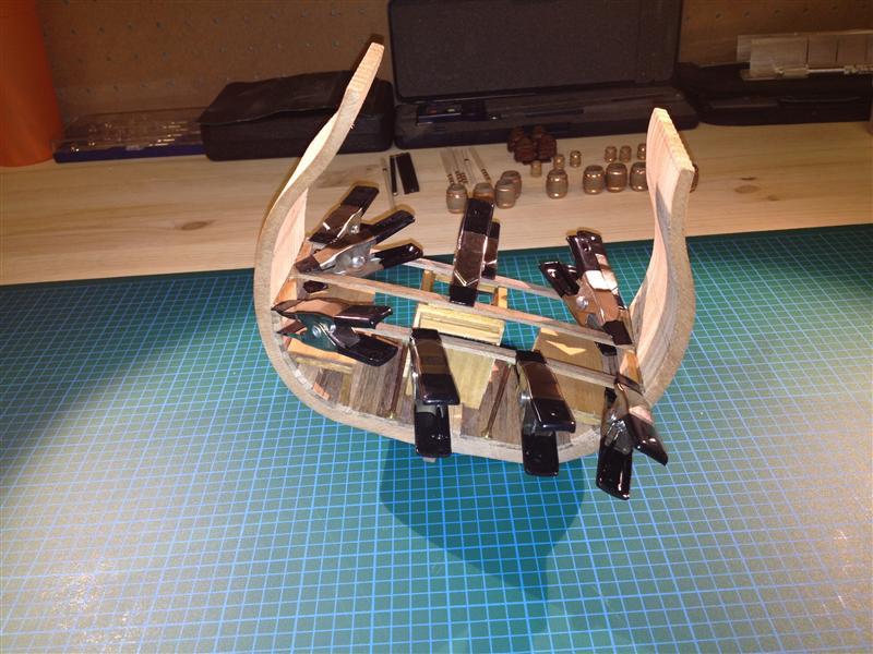
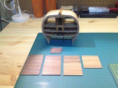
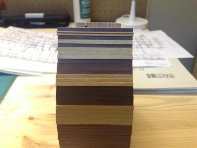
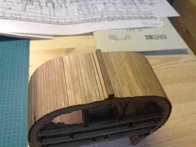
I haven’t had much time to work on my Victory in the last three weeks, but I’ve made some good progress in the last four days. For a change of pace, I decided to plank the outer hull. I started by cutting the required number of strakes, and then sorted them by colour. The lighter walnut will be used for the areas nearest the keel that will be covered in copper plating while the darker walnut will cover the exposed areas (I don’t plan to paint the model, so the colour of the wood is important to me). Walnut cut and sorted. The keel fully planked. Port side fully planked. I really like the contrast between the boxwood and the walnut. Perhaps this is a nitpicky point, but I think this is the exact opposite of the colour scheme on the actual Victory. I’m not sure why Corel chose to do this – probably because boxwood is more expensive than walnut? Starboard side fully planked. Port and starboard gun ports and entryways (I cut these out by hand using a #11X-ACTO knife and a small file). As I mentioned earlier, while I like the kit, it simplifies and generalizes many details. This section of the Victory should include a portion of the bulwarks, so I’ve had to construct these from scratch. Much sanding is still required on the cross section face.


- 42 replies
-
- 1
-
-
- cross-section
- corel
- (and 2 more)
-
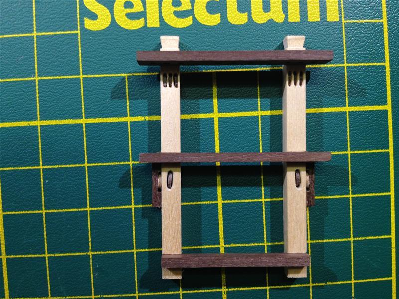
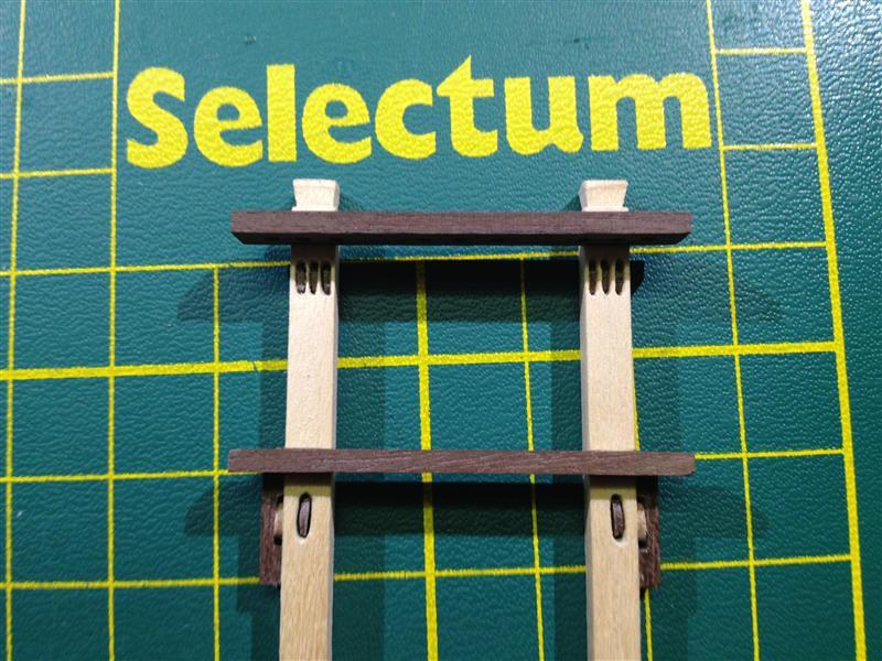
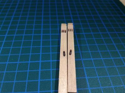
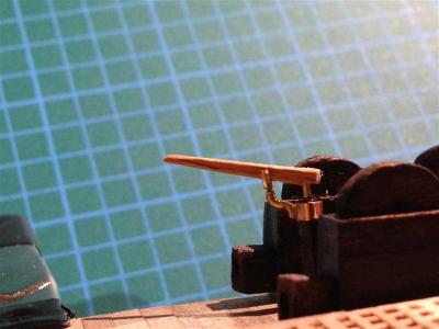
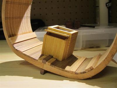
As I've mentioned, the Corel kit omits many details, including the jeer bitts. These extend from the middle deck to the upper deck. I crafted them from boxwood and walnut, with all the sheaves cut out and installed by hand (# 11 X–ACTO blade). The hardest part of making the jeer bits was keeping everything square during the gluing and installation.


- 42 replies
-
- 1
-
-
- cross-section
- corel
- (and 2 more)
-
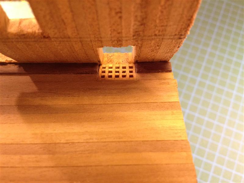
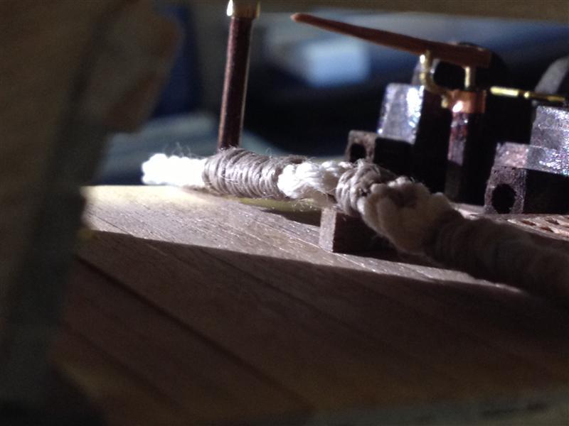
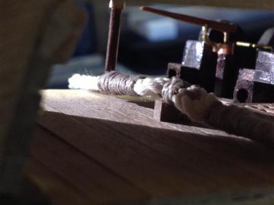
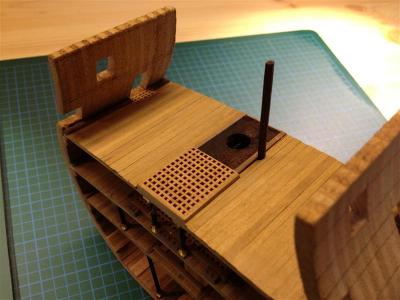
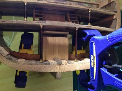
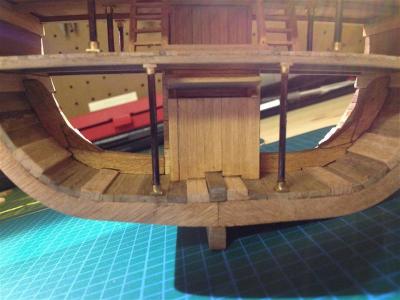
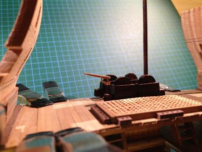
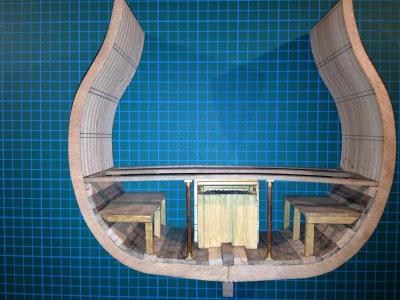
I made a little progress on my Victory cross section this week; I’m currently waiting for some walnut strips to arrive to fabricate new bitts, so I have time for an update here. I finished construction of the gun deck (I’ll install the cannons later) by adding the cradles for the anchor cables. These were made from walnut scrap. The anchor cables are modeled after an image in Longridge. Thus is just a dry fit, as I plan to finish the model with tung oil and will glue them in later. They look very large in photos, but they are built to scale, or very close. I’m not happy with their “fuzziness”, so I’ll have to trim them under magnification. The middle deck on the Corel kit doesn’t include entry port gratings, so I’ve added them (to scale) here. I’m fairly pleased with the result. According to McKay, their scale is supposed to be the same as the hatchway gratings, so I used some leftover stock from the kit. Progress shots of the middle deck. Next time: scratch built bitts!


- 42 replies
-
- 2
-
-
- cross-section
- corel
- (and 2 more)
-
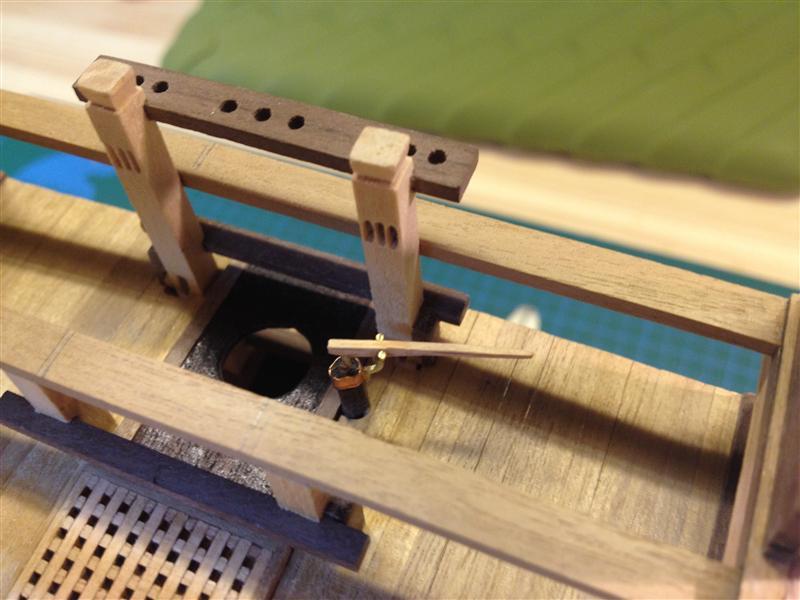
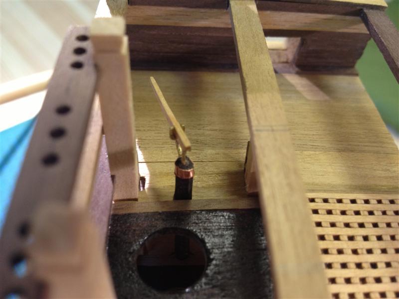
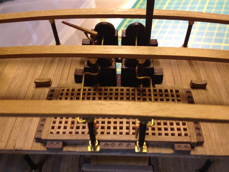
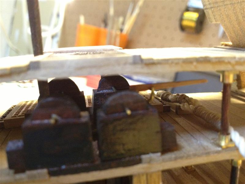
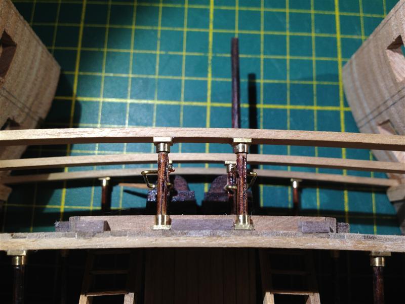
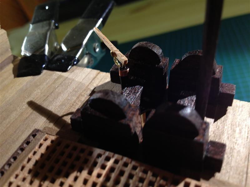
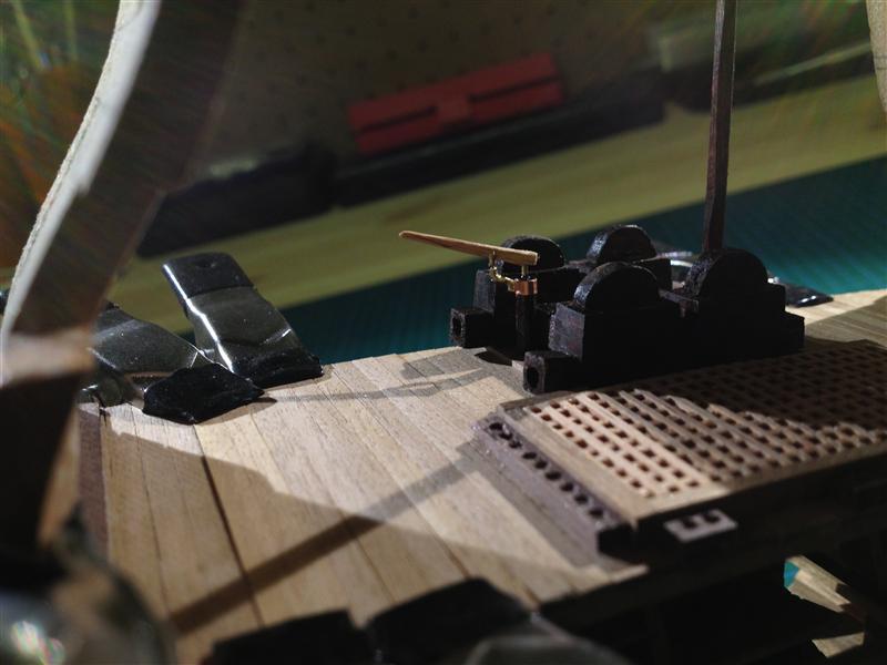
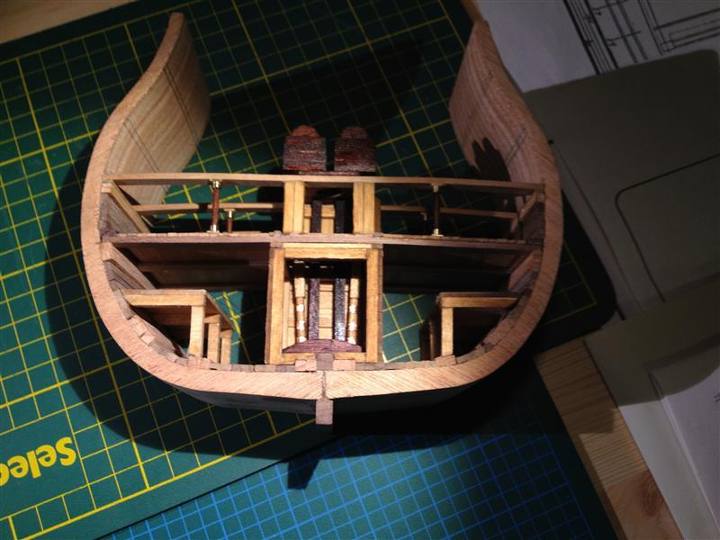
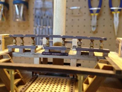
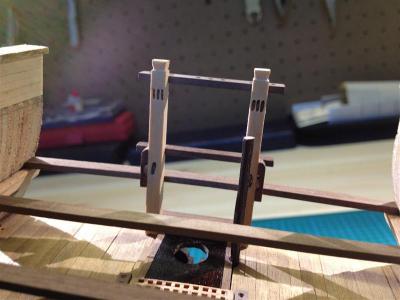
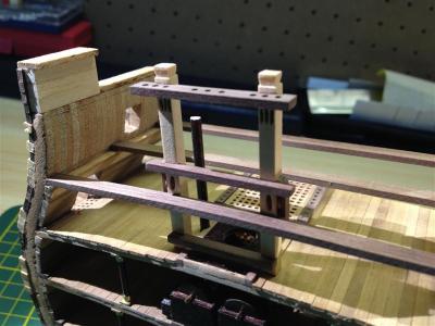
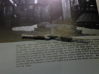
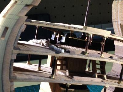
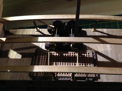
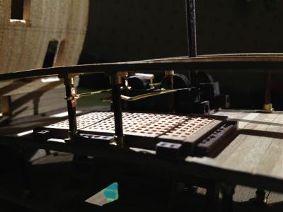
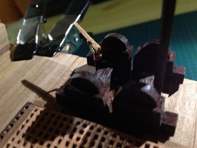
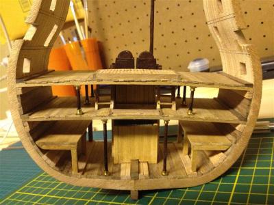
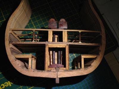
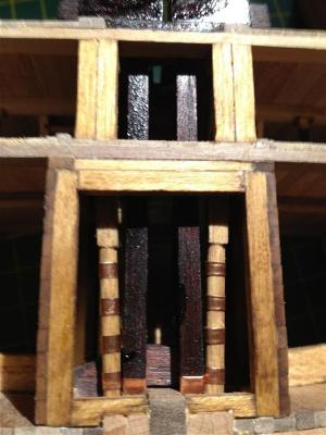
It’s been a busy week, but I’ve finally had a chance to install the chain pump crank handles and the pillars. Both sets of the forward pillars are in the proper positions but the aft pillars are not. On the real victory the aft pillars are just behind the pump casings, in a location not represented by the cross section. However, to maintain the convex shape of the middle gun deck I had to install the aft pillars, so these are placed slightly forward and lateral from their actual position on the ship. The crank handles are constructed from brass wire and attached to the pillars with copper strips. Both fittings are made from iron and painted black on the actual Victory, but, as I mentioned in a previous post, I’ve decided to use only brass and copper for metal fittings in this build.


- 42 replies
-
- 2
-
-
- cross-section
- corel
- (and 2 more)
-
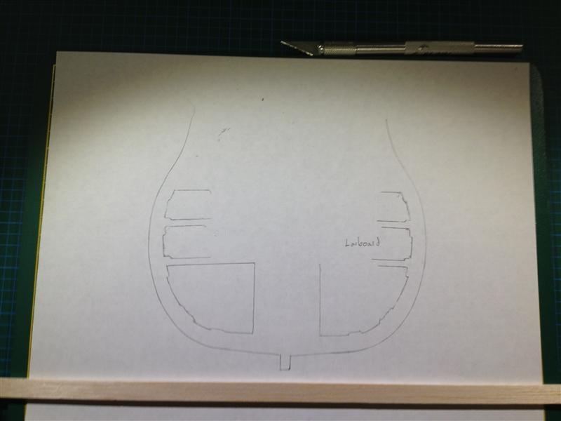
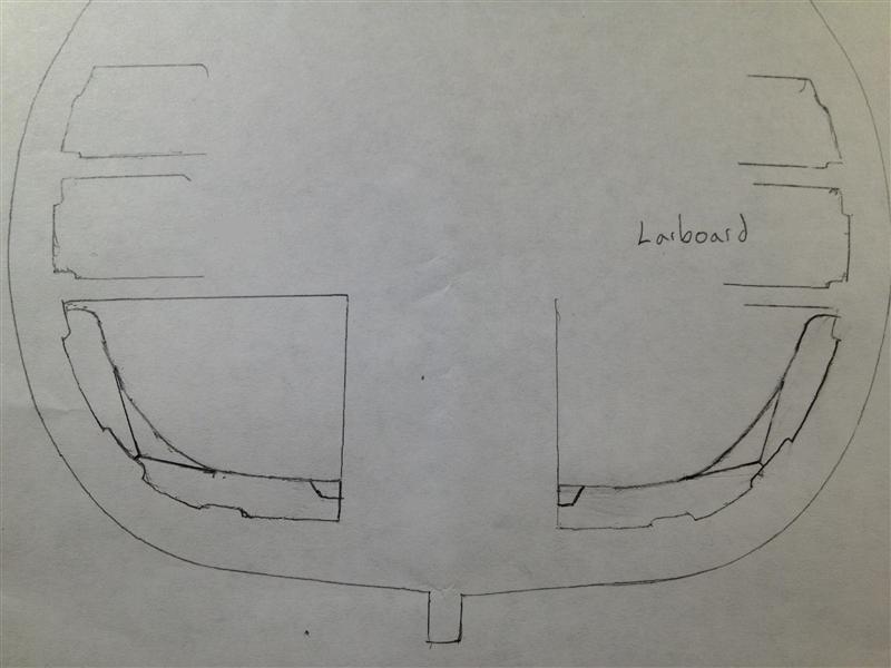
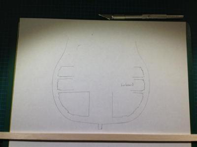
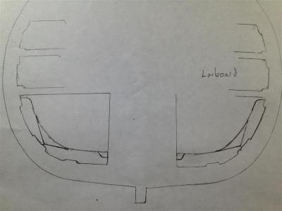
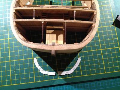
After making some progress, I've decided that I should have added the one rib that occurs within this cross section of Victory to the model. At this stage in the build, this represents three problems; 1) I’ve already installed the orlop deck, 2) I’ve installed the hold well, and 3) I’ve installed the hold platforms. The rib runs through all three, on both sides of the ship. My solution was to remove the hold platforms and build the rib in two sections placed on either side of the hold well (the area where it passes through the hold well can’t be seen anyway). I’ll cut and fit the hold platforms to sit around the ribs, but I determined it would be too destructive to cut through the deck and install the upper portion of the rib. So, the upper portion of the rib will be left out of my model (and I’ve learned a good lesson for the next build). Here are some pictures of the process: Hold platforms removed, revealing a mess of dried glue. Broken hold platforms. Not to worry, this will give me a chance to make more accurate framing and posts! A tracing of interior of the hold deck was needed to create a custom template for the ribs. Lower portion of rib sections drawn to scale… The finished templates. Three sections of the port rib, with a light oak stain. Gluing the ribs in place. The final installation.

- 42 replies
-
- 1
-
-
- cross-section
- corel
- (and 2 more)
-
A photo of the shot garlands installed. The instructions only called for shot garlands on the port and starboard margins, but I’ve added the fore garlands as in the original ship. Unfortunately, I used all the shot provided with the kit in the shot locker - I’ll have to order more!
-
Here are some images of the elm tree pump on the gun deck. The original has black painted iron for the pump assembly, which I’ve reproduced here with brass wire and copper tape. I found it very challenging to glue the brass and copper together – even CA wouldn’t work. I had to buy a special metal one metal glue.

- 42 replies
-
- 1
-
-
- cross-section
- corel
- (and 2 more)
-
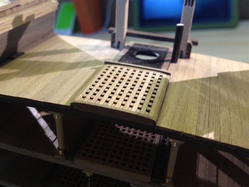
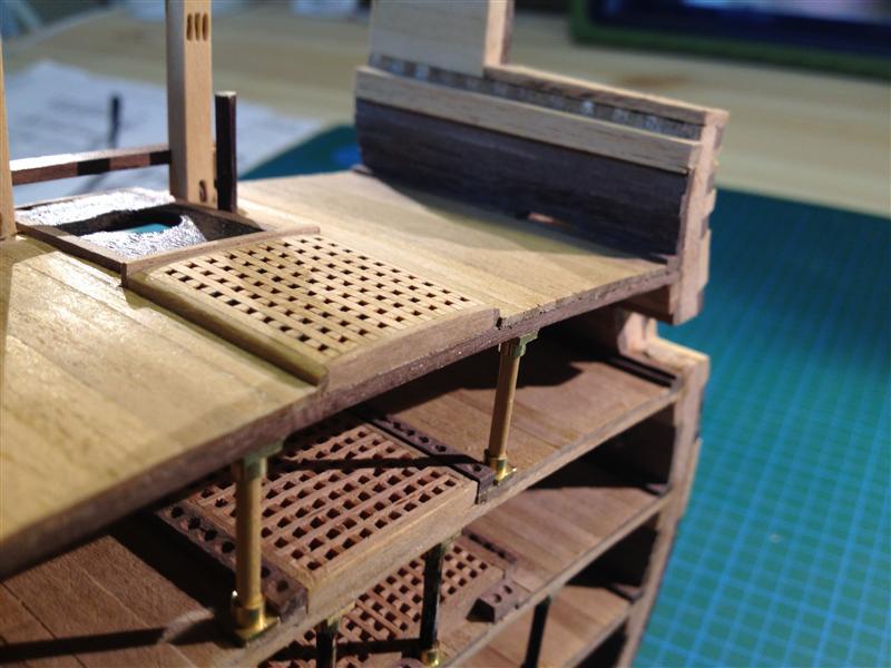
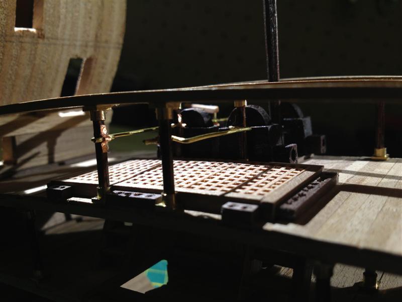
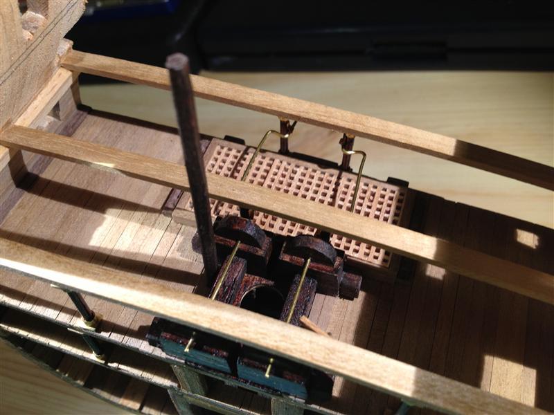
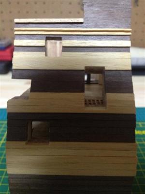
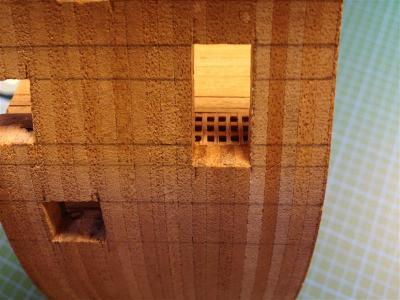
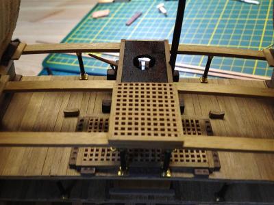
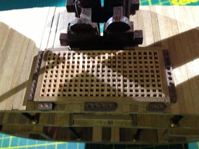
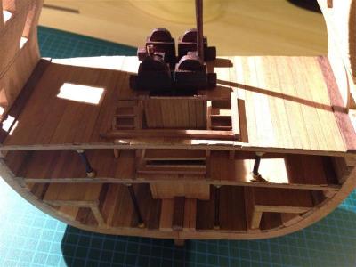
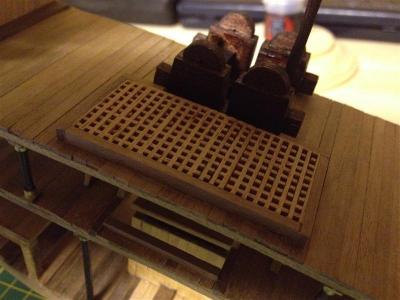
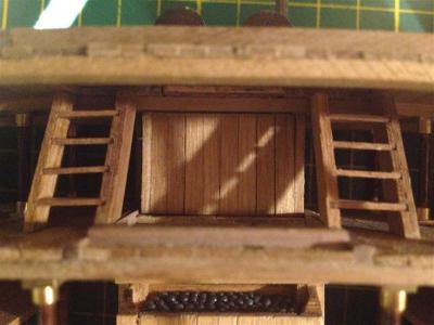
Here I’ve installed the gun deck planking, hatch, and companionways. The companionways aren’t positioned here in the real Victory (they are just foreward of this location), but I’ve included them anyway to display this aspect of the ship’s construction. As a result of the companionways, the hatchway is somewhat larger than the Victory’s hatch in this location. This picture also shows the chain pump casings more clearly, as well as the spouts I’ve added to all four casings. The elm tree pump shafts are also installed here. The Corel model instructions indicate that the hatch on the gun deck is to be open, but in the real victory a grating covers this hatch, so I’ve installed one here. Cutting the gun and entry ports involved some careful measurement and patience; I drilled two holes in each port and then cut them out using a new # 11 xacto blade. Here is a macro shot of the orlop deck; despite being slightly inaccurate, I like the look of the companionways here.

-
In this sequence I have installed the pump room and pump casings, along with the pump shafts. I’ve left the back of the hold well open so that these can be seen (the aft cross section cuts through this area in almost exactly this position anyway). The step can be seen in the hold well in this view. The elm tree pumps and pump casings are stained with a red mahogany finish (still wet in the photos).

- 42 replies
-
- 1
-
-
- cross-section
- corel
- (and 2 more)
-
This is a better view of the hold platforms and shot lockers from the last post. I made two mistakes here; first, by not building the posts and frames of the hold platforms to scale, and second, by not installing the riders when I had the chance. I originally didn’t want think it was necessary to install the riders (I thought they would be obscured by the ballast, hold platforms, and barrels, but I’ve since regretted this. Later on in the build fix the scale of the hold platforms and install riders. More on that later...
-
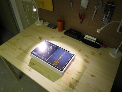
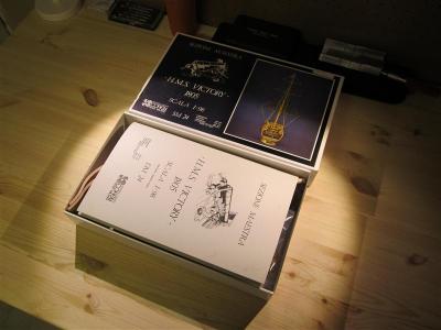
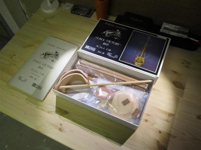
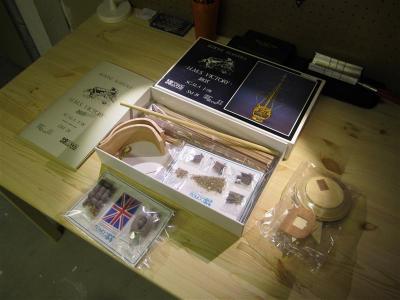
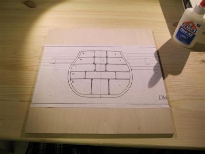
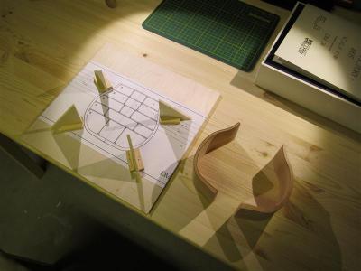
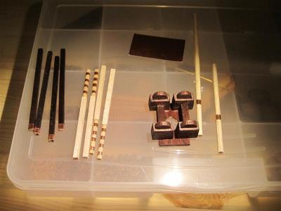
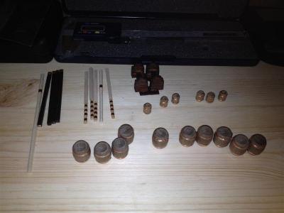
Here goes my Victory cross section repost on MSW 2.0!! ---------------------- Hello Everyone, I have been a long time visitor to the MSW forums and I have marveled at the craftsmanship and attention to detail displayed in so many of your projects. Now it’s time to share my first build with you. I’ve started small, with a 1:98 scale HMS Victory cross section kit by Corel. While I find the kit to be excellent, it is a simplified model, so I’ll be modifying it to include more detail. As my guides I’ll be using McKay’s and Longridge’s books, hundreds of internet photographs, as well as all of the great information on MSW. I’ve also found the following website very helpful, as it includes a well-reasoned list of modifications to make the kit more accurate: http://www.mountainhaven.com/VictoryXCP/index.html My goal isn’t to follow this list precisely (for example, I won’t me modifying the deck framing to be more accurate), but I will be adding major details such as the step, chain pumps, shot lockers, elm tree pumps, hold well, pump room, and other details. I’m a few months into the project, so it will take me a little while to catch up here. Like many of you, I’ve also removed and reworked/improved some of my earlier modifications to add more detail, so expect some changes along the way. Until the next post, enjoy the “unboxing” photos. E&T My workspace and the kit: The unboxing: Gluing a photocopied plan to a board to create a jig: The finished jig for aligning the frame: Keel, keelson, deck planking, shot locker and pump well installed. Unfortunately I forgot to take a picture of the step, but you’ll see more of that later. The pump well and locker are made from balsa, with a light oak stain. The hold platforms prior to installation: Parts fabricated for installation, including the chain and elm tree pump shafts and the chain pump casings. The shafts will be fitted inside the hold well and pump room and will extend from the hold to the lower deck (gun deck), where the chain pump casings and starboard elm tree pump will be installed. I’ve decided not to paint the model, but to use natural oiled or stained finishes. Any metal fittings will be made from brass or copper. Here, iron fittings are replaced with copper (including barrel hoops). So far, I like the look. Here you can see the framing for the orlop deck being glued, with the fabricated pump room in the background waiting to be installed.

- 42 replies
-
- 2
-
-
- cross-section
- corel
- (and 2 more)
-
This looks like a great kit and you are making fantastic progress. What is the scale?