Erebus and Terror
-
Posts
410 -
Joined
-
Last visited
Content Type
Profiles
Forums
Gallery
Events
Everything posted by Erebus and Terror
-
 Beautiful clean work - the ports look lovely.
 -
I have to agree with Sherry. You certainly practice what you preach. Superb work.
- 1,215 replies
-
- 2
-

-
- sloop
- kingfisher
- (and 1 more)
-
Wonderful work!
-
Very fine work. I'm still marveling at the symmetry. Ships of this era (and style) don't receive enough attention, and I'm glad to see such a detailed log.
-
Thank you Ed, I certainly will do so. I've actually found deionized water at my local Canadian Tire (if you live in Canada that is).
-
Wow - that is complex. Just excellent work.
-
Jason, Karl, and Gabe thank you for the words of encouragement. Much appreciated. Gabe, those are excellent books, Barrow's Boys in particular. It's a fascinating period for the Royal Navy, and these ships are really the bleeding edge of technology for the day. Peake, Seppings, and Lang really poured a great deal of creativity into the vessels, most of which spilled over to the rest of the fleet.
-
Good advice, Ed. Many thanks! All three are pretty serious chemicals so I don't take chances; safety goggles, rubber gloves, and open ventilation are a must. You and Druxey have given me good advice on alternate agents and I'm certainly willing to experiment....with all the metal work on this ship I need to find some process that will give consistent results.
-
Alex and Ed, many thanks for the positive reinforcement! Ed, thank you very much for your detailed comments. I have seen your posts about copper and I admit that I am intrigued - especially by the use of copper solder. I have never heard of WinOX but will have a look for it. I feel that if I could recall my high school and university chemistry better I might at least be able to understand why I get such variable results! As Druxey mentioned, I suspect my water and prep may have something to do with it. Perhaps not enough time in the HCL...
- 346 replies
-
- 1
-
-
- terror
- polar exploration
- (and 2 more)
-
Having just completed much simpler (i.e. flat) straps on my build, I have to say that is very nice indeed. Impressive detail.
-
Interesting, thanks Druxey. Blacken-it sometimes doesn't play nice with solder...I'll definitely check it out.
-
Thanks for the advice, Druxey! I use bottled water. I've never tried deionized water, but will give it a shot next time. I've also thought of changing brands, but blackening agent is hard to come by in Canada.
-
Thanks for the compliment, Druxey - much appreciated. Unfortunately these are already buffed multiple times so this is going to be about as good as it gets. I've never been able to achieve anything but an uneven and flaky surface with Blacken-it, despite relatively rigorous preparation with muriatic acid and acetone.... perhaps I'll do a post about it tonight. So, all that work and still the uneven appearance. Despite that, I'm fairly happy with the finish. I think the highs and lows approximate real wrought iron fairly well. Oh, and good eye for the wood. These metal pieces aren't glued in place yet, and I still have lots of work left to do on the wood.
-
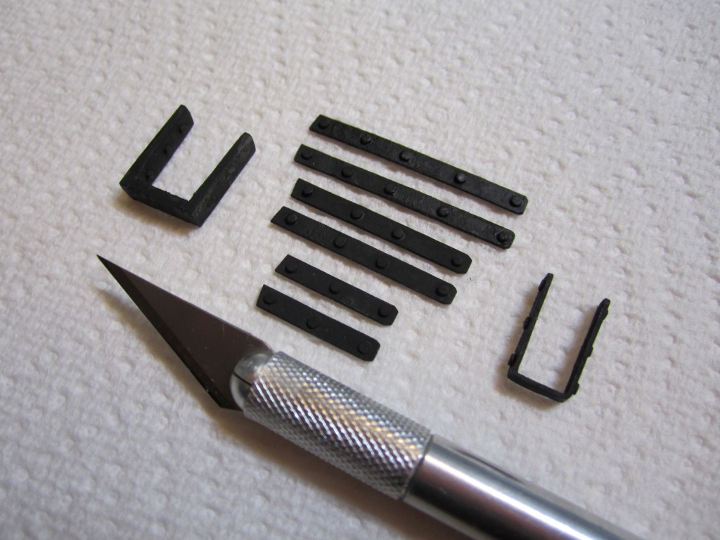
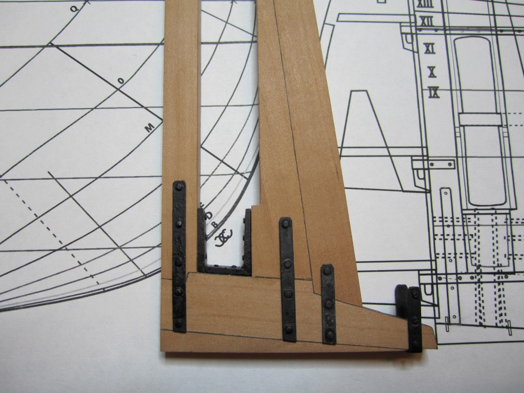
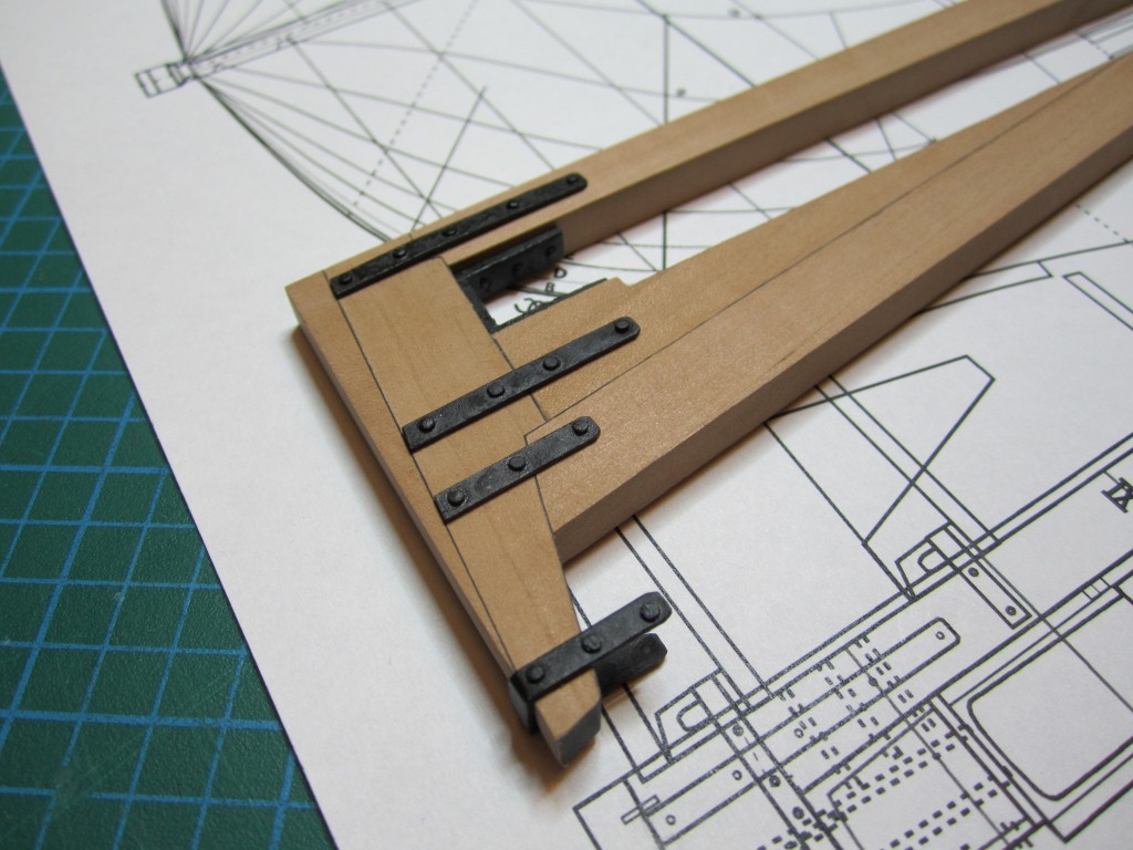
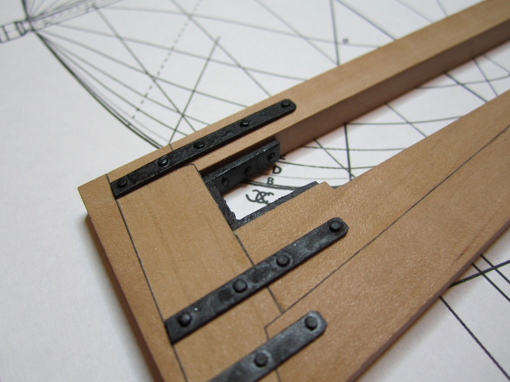
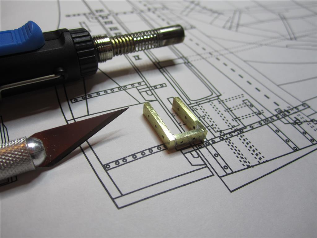
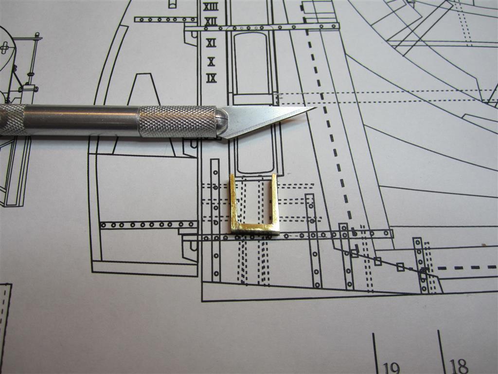
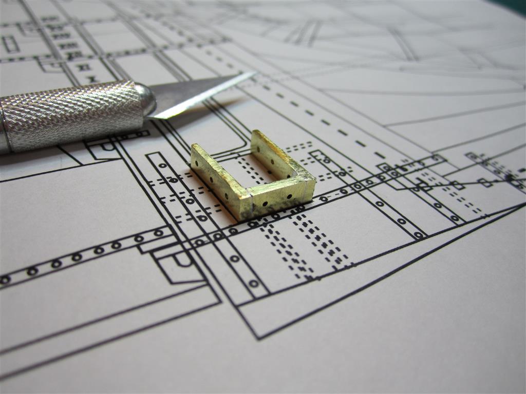
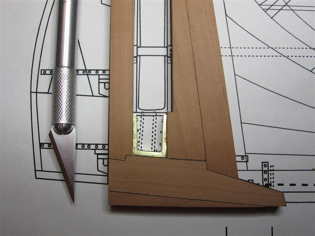
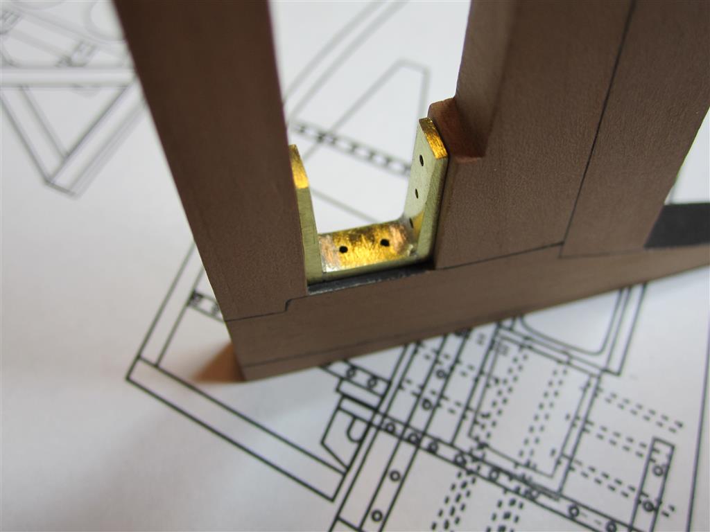
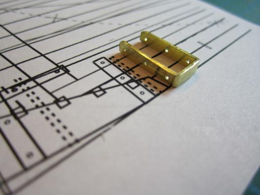
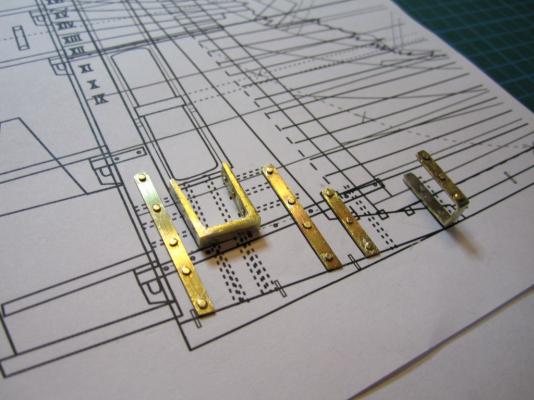
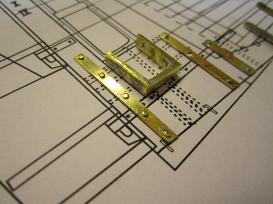
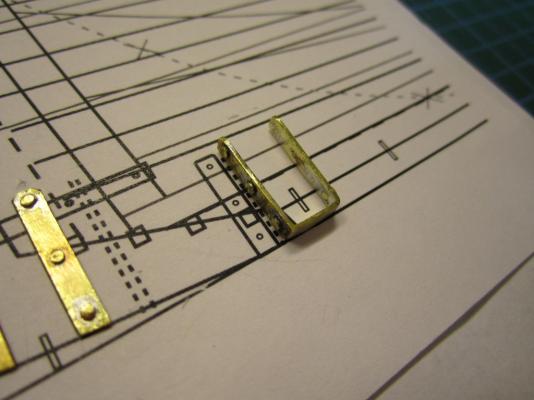
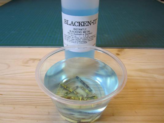
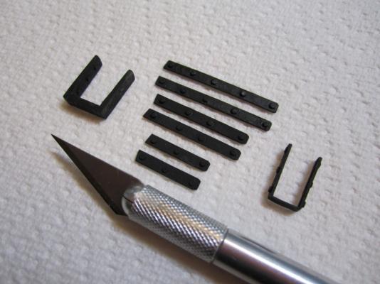
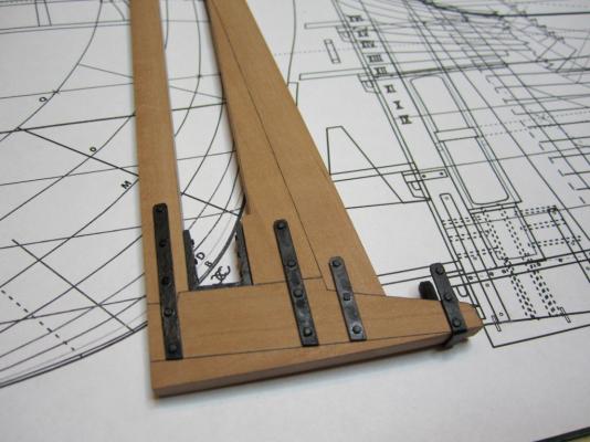
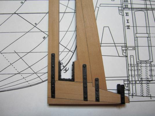
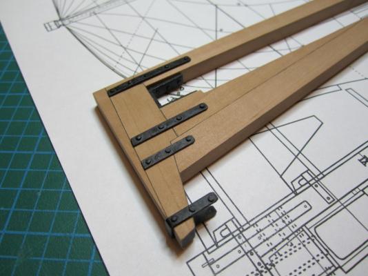
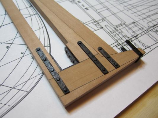
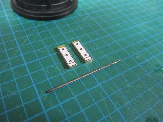
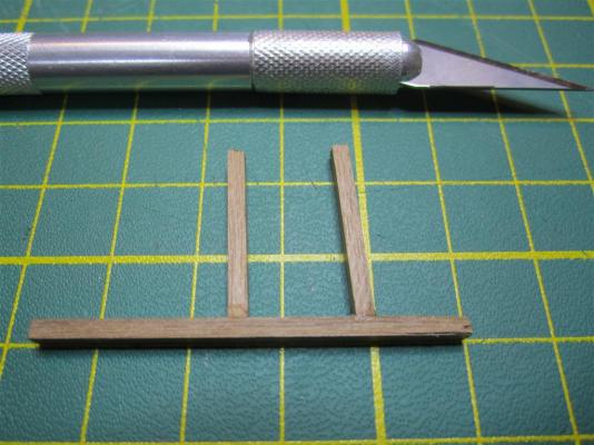
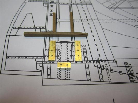
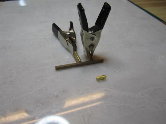
IRON WORK Oliver Lang’s 1845 modifications to Terror’s stern involved a significant amount of iron reinforcement. In my last post, I documented the design of the iron staple knee, which was central to the construction of the propeller well and new rudderpost. However, Lang also added four large iron straps to reinforce the joints between the keel, the rudderpost and the sternpost. These straps were u-shaped and passed between the false keel and the keel, permitting the former to break free in the case of the stern running aground. According to Lang’s notes, the straps appear to have been bolted entirely through the width of the stern to provide extra rigidity. This created an exceptionally strong iron-laced structure, a design which exposed Lang's worry about the ice pressure to be exerted on the Terror’s stern. The 1845 stern modification plan reveals that the straps were 4 and 1/2 inches wide, with bolts approximately 1 and 1/8th inches in diameter. I estimate, based on bracing and strapping shown on cross section plans of HMS Erebus/Terror and HMS Investigator, that they were ca. 1 to 1.5 inches thick. All of the parts shown below are made from larger brass strips, which were cut, filed, and drilled by hand. The bolts are made from brass straight pins; the heads were filed by hand to scale (2 inches) and soldered into place. The brass was then blackened to simulate iron. The foremost strap prior to adding the bolts. The staple knee and remaining straps with bolts soldered in place. The three aft straps would normally look similar to the one on the right, but I've decided only to model the visible portions of the straps (i.e. the portions not buried between the keel and false keel). Each is composed of two parts to be glued on opposite sides of the model. Detail of the newly added bolts. Brass parts soaking in the Blacken-it diluted to 6:1. The finished parts. The iron reinforcements in place (dry fit only until the propeller rails are completed). Again, just a test to see how they will look when finally installed.

- 346 replies
-
- 18
-
-
- terror
- polar exploration
- (and 2 more)
-
Beautiful photos. Looks like the real deck....and nice save on the knees!
-
Very clean and precise...beautiful brass work and planking. She's really coming along!
-
Nice progress on her. Very fine work.
-
You consistently raise the bar, Remco. Simply Amazing.
-
Wonderful work!
-
Druxey, Mark, and Michael thanks for positive the comments. Yes, the joint is incredibly strong. Still being a novice, I used far too much solder initially and had a lot of clean up to do on the piece. The pictures were far too ugly to post here!
-
Beautiful, beautiful work....
-
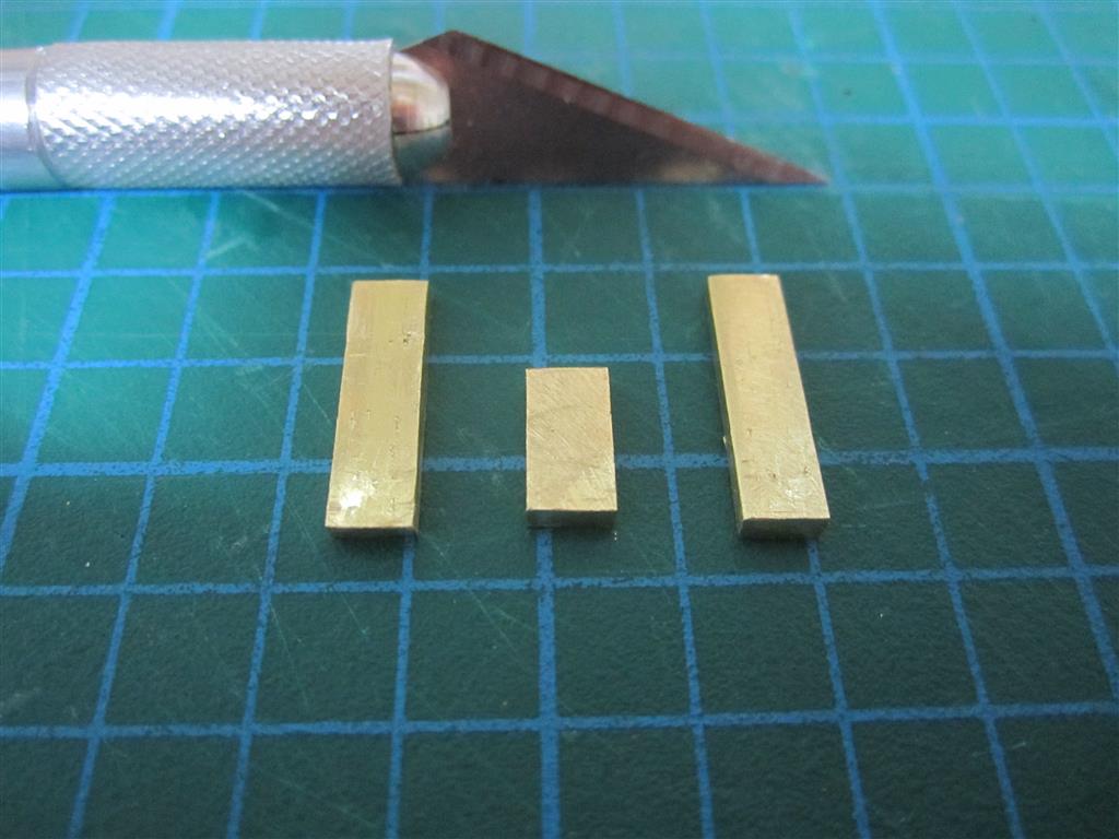
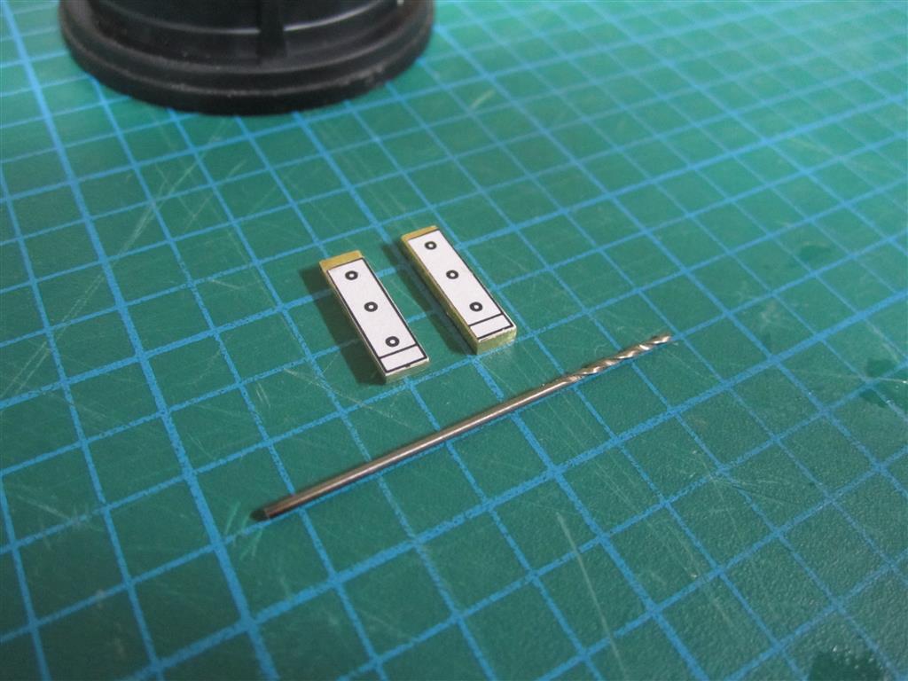
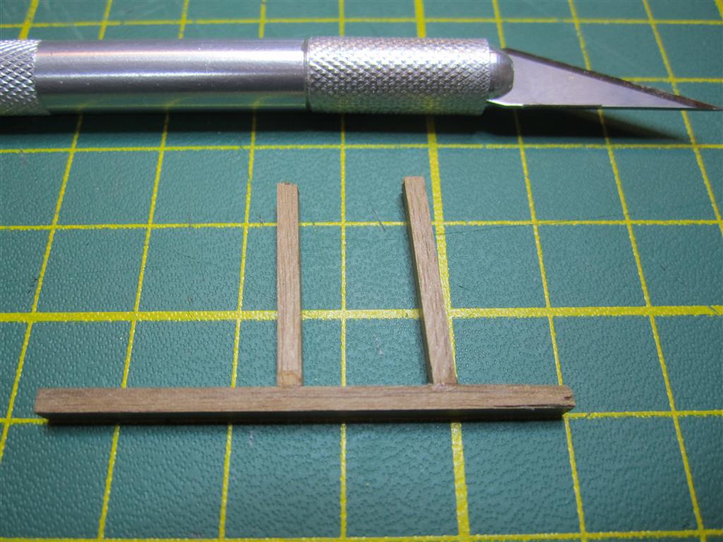
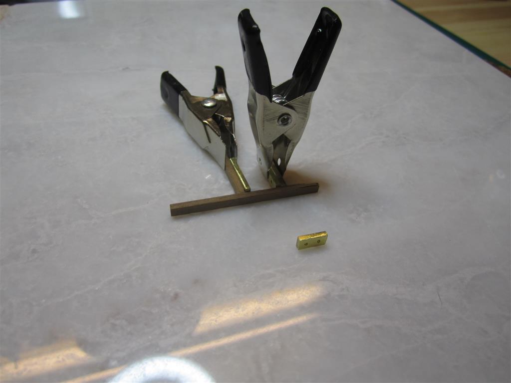
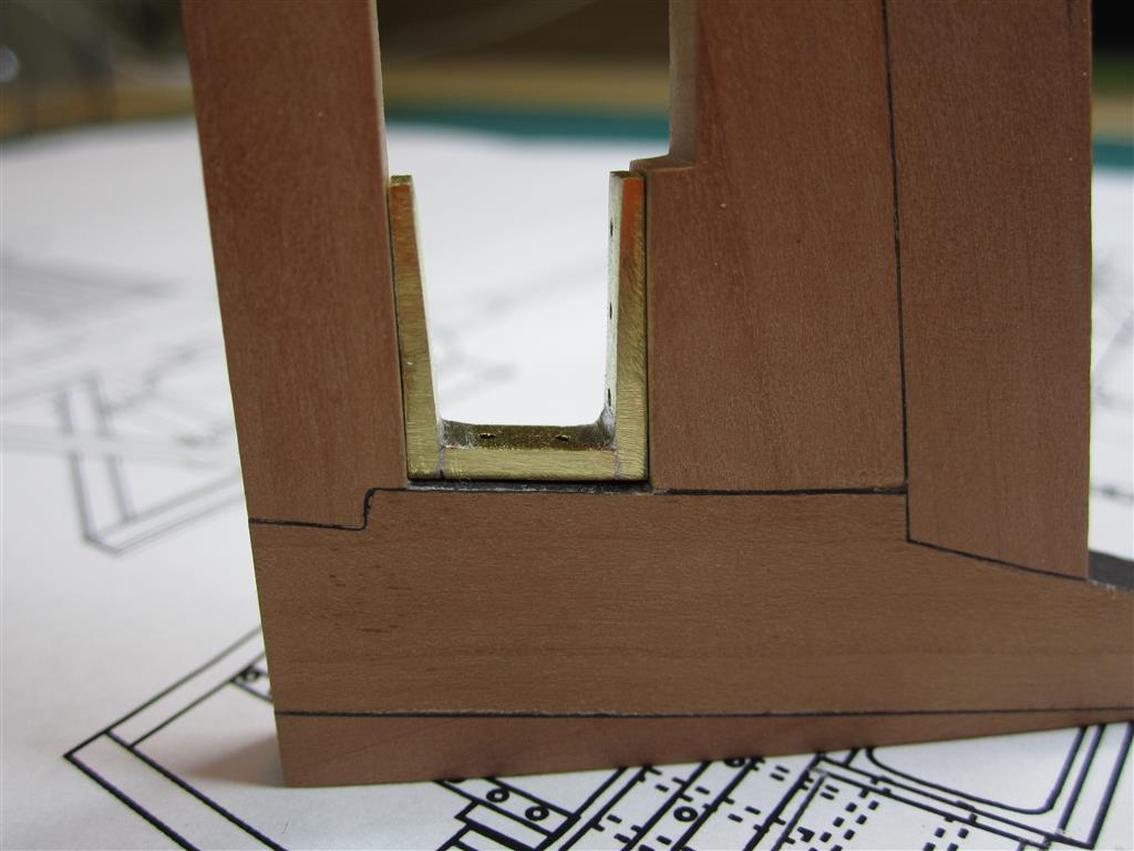
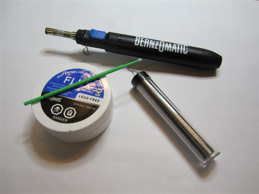
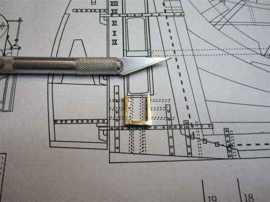
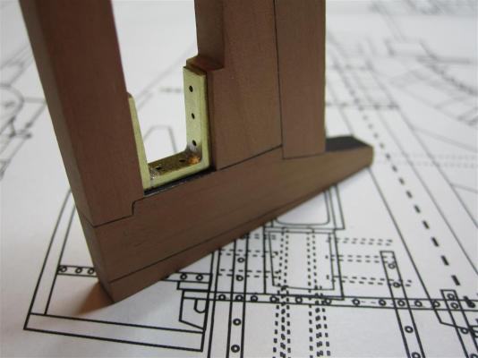
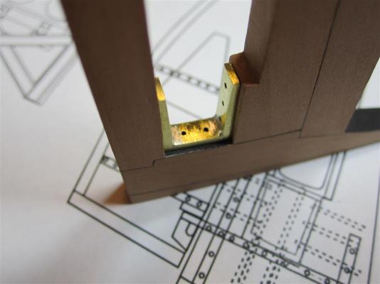
MODELING THE "IRON STAPLE KNEE” In my last post, I described Oliver Lang’s unique modifications to HMS Terror’s stern to accommodate the screw propeller. A primary component of this modification was a massive 3.5 inch thick “iron staple knee”, which securely bound the keel, original sternpost, and rudderpost together. To model this part, I originally attempted to bend and hammer a 1.85 mm thick piece of brass into the correct shape, but try as I might, I could not create the appropriate angles accurately and only produced a mangled mess. Finally, I resigned myself to the fact that I would need to cut three separate pieces and then silver solder them together. I had never attempted this before, but I found a great deal of information on Model Ship World, and decided to give it a try. Brass stock cut to match the dimensions of the three sides of the knee. Preparing to drill the holes for the bolts. The drilled pieces. A rough jig necessary to hold the pieces in place while soldering. My new pen torch and other soldering equipment. Clamping the pieces to the jig. It was a tricky task not to burn the jig, but thankfully the joints were small and the brass heated rapidly. The knee after soldering. The joints are much stronger than I hoped they would be. The final part filed to shape and compared to the plans. An alternate view of the finished part. The knee dry-fitted to the stern piece.


- 346 replies
-
- 18
-
-
- terror
- polar exploration
- (and 2 more)
-
Thank you, Druxey. Much appreciated.
-
Thanks Antony, David, and John!