HOLIDAY DONATION DRIVE - SUPPORT MSW - DO YOUR PART TO KEEP THIS GREAT FORUM GOING! (Only 13 donations so far - C'mon guys!)
×

Erebus and Terror
-
Posts
410 -
Joined
-
Last visited
Content Type
Profiles
Forums
Gallery
Events
Everything posted by Erebus and Terror
-
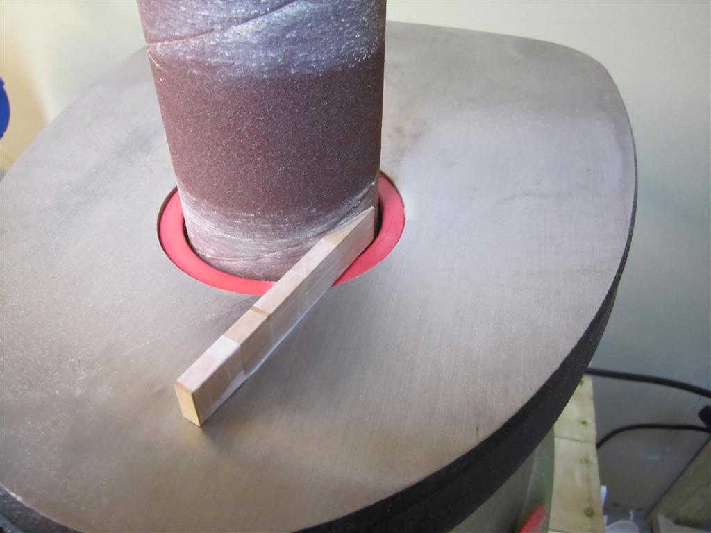
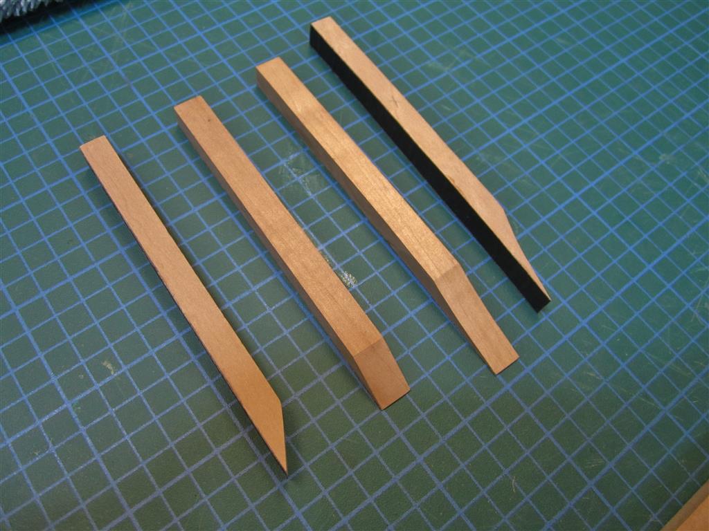
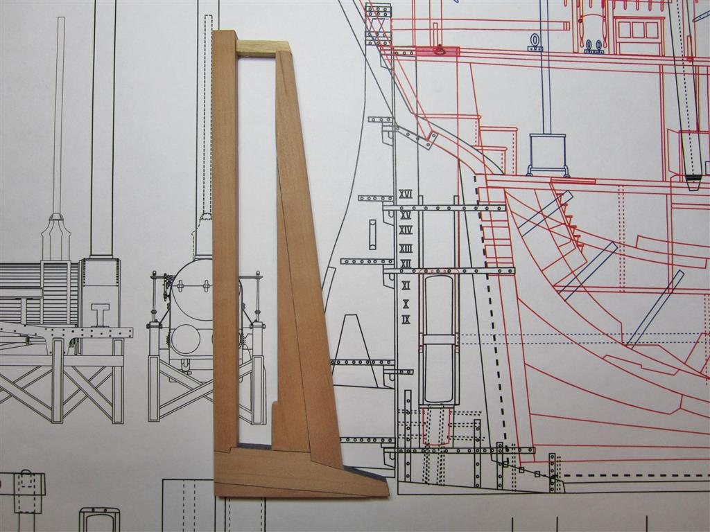
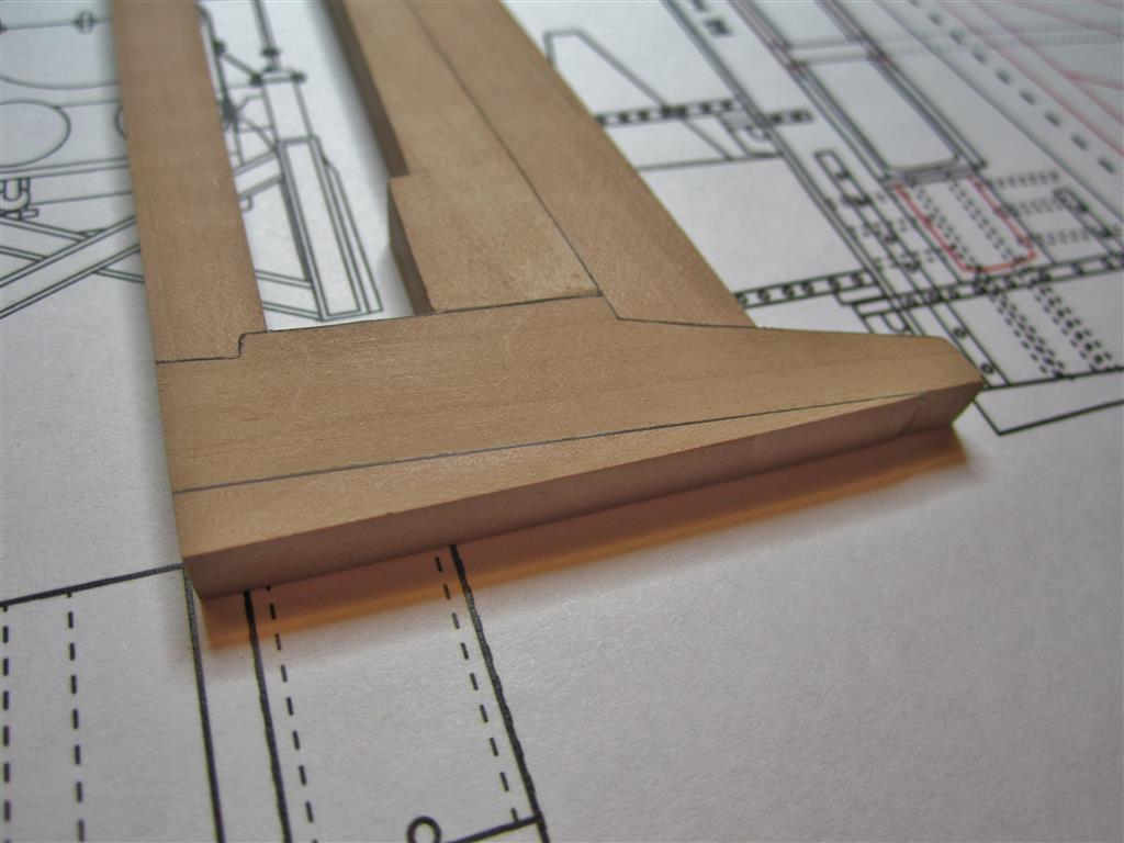
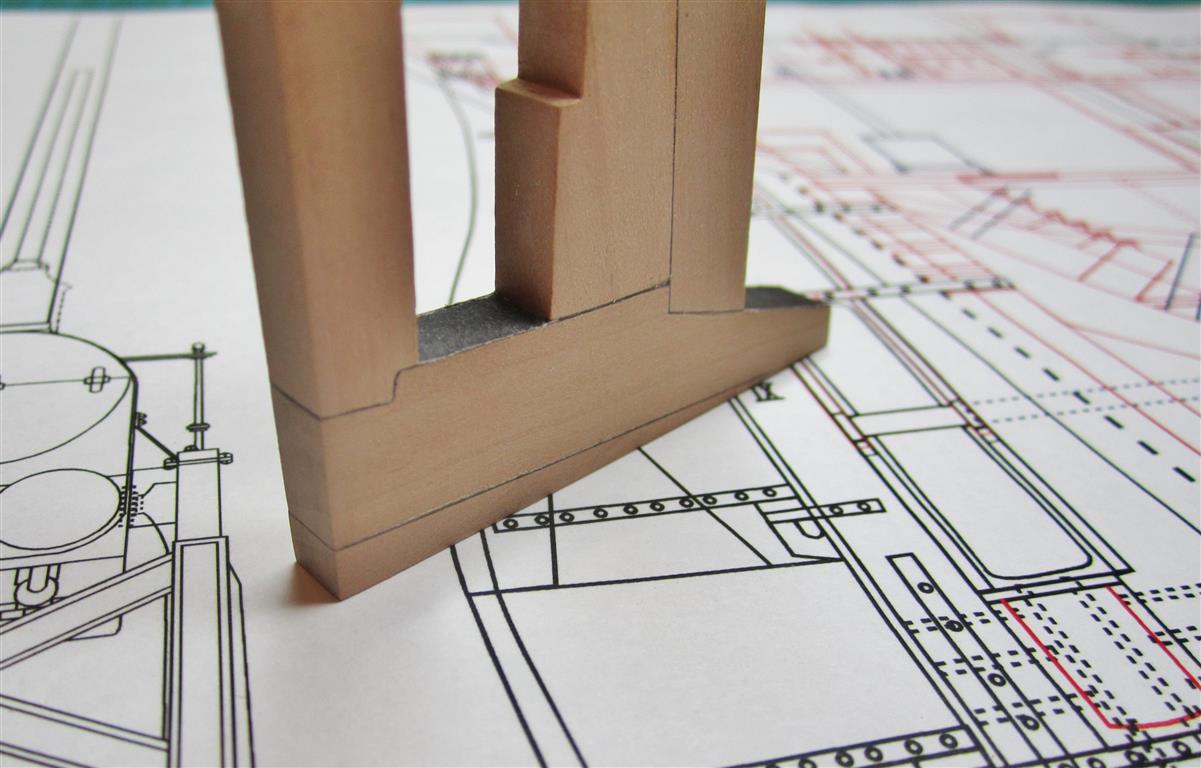
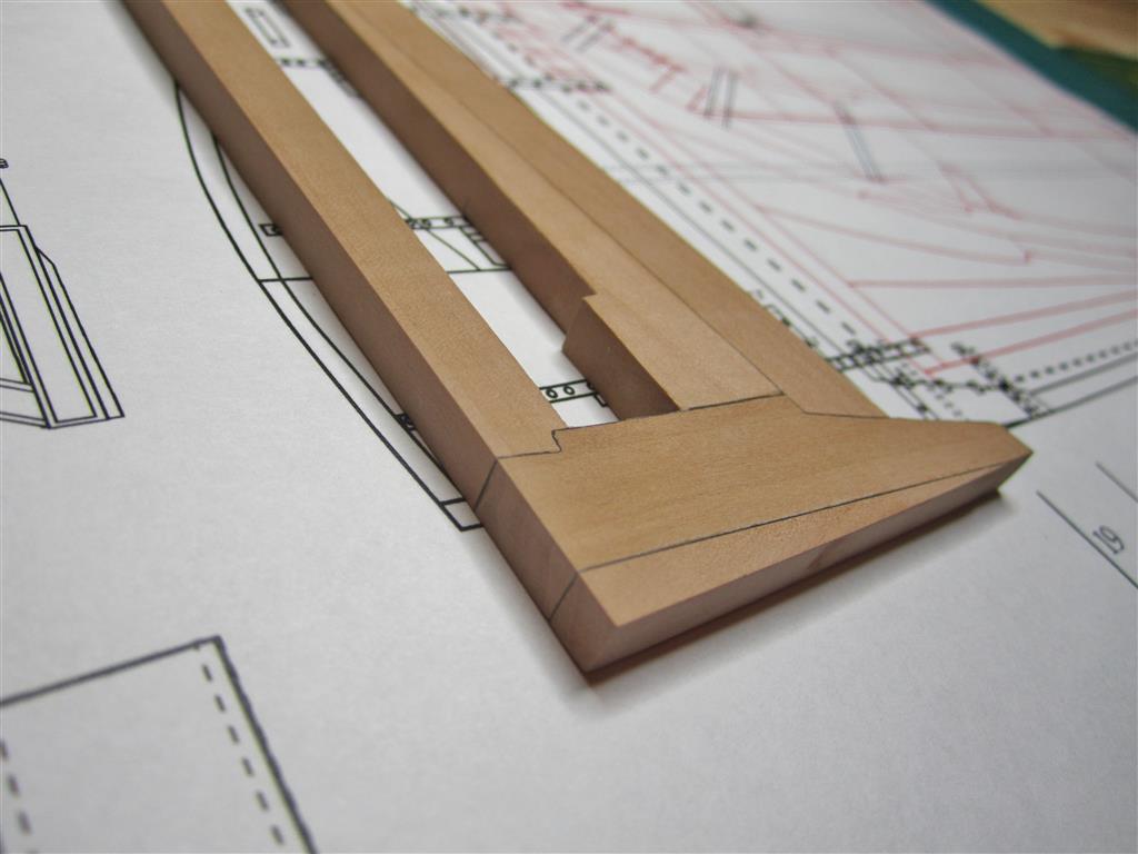
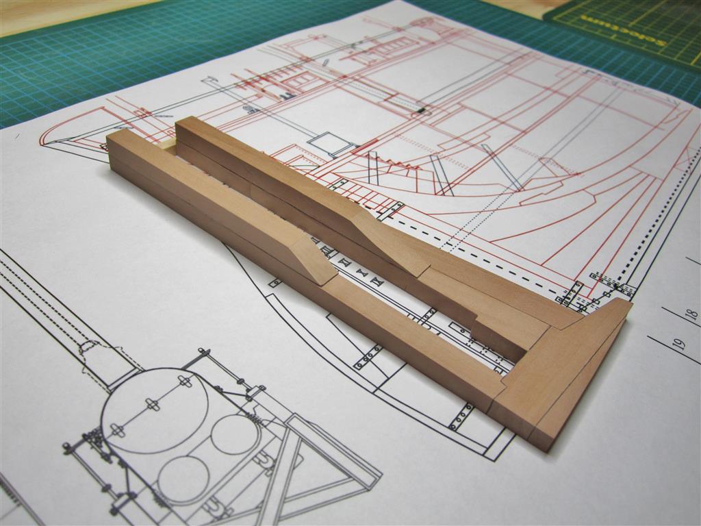
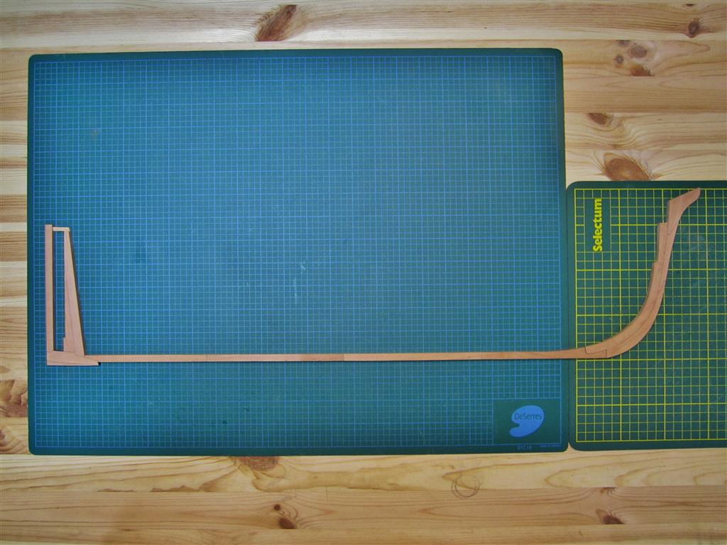
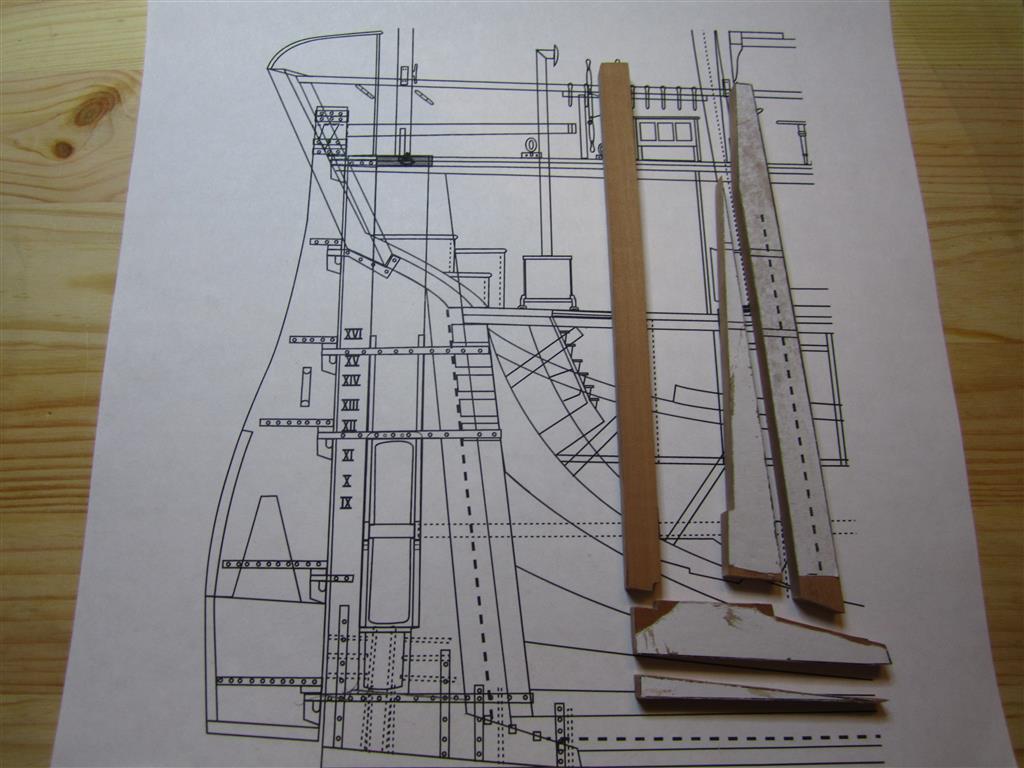
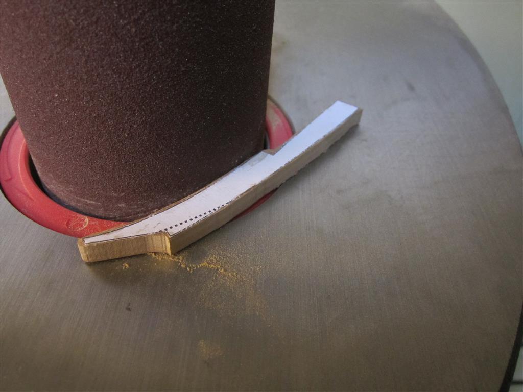
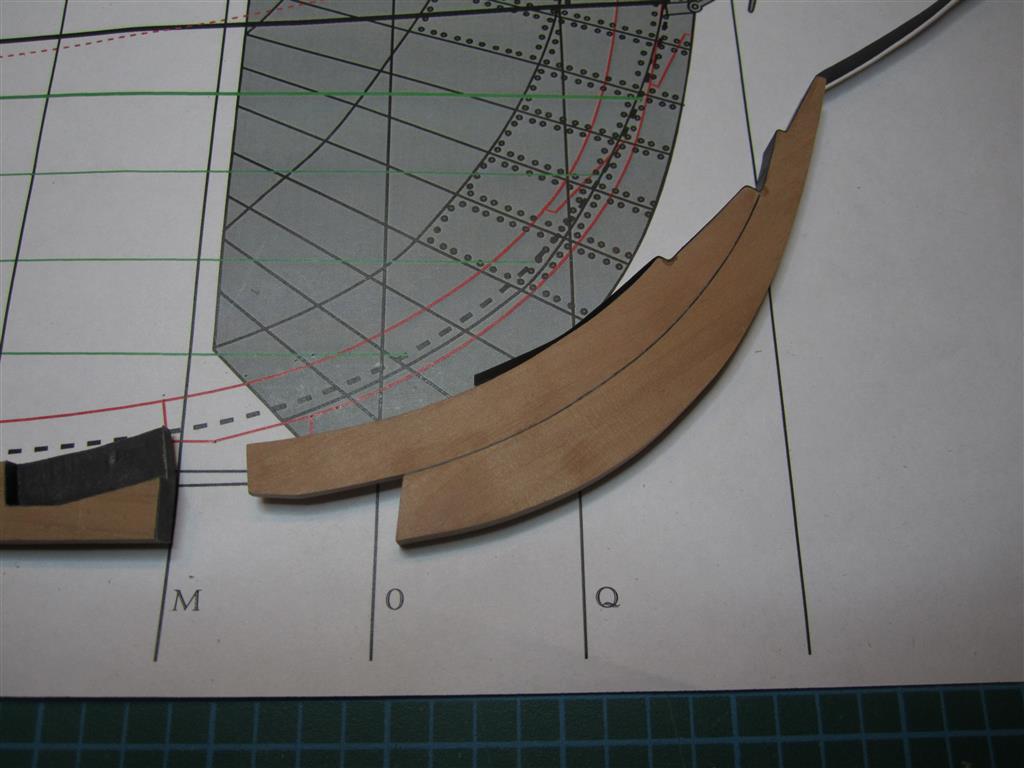
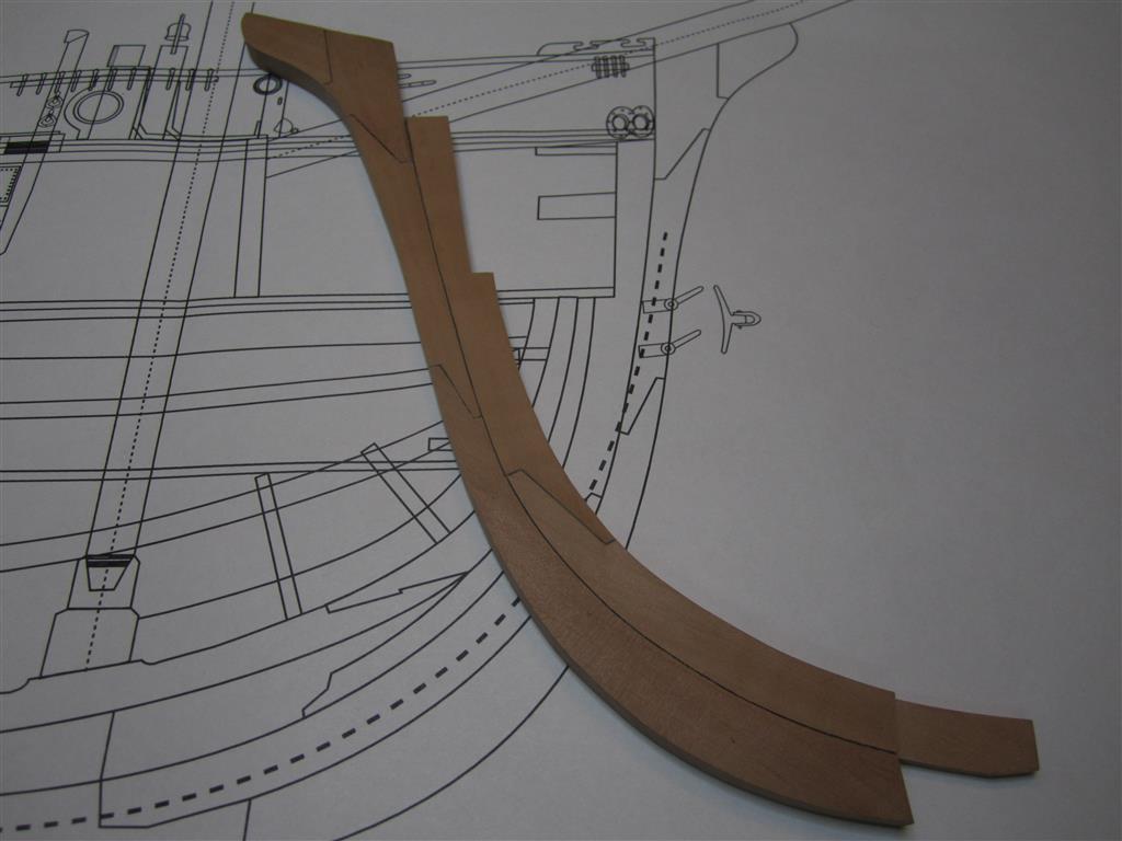
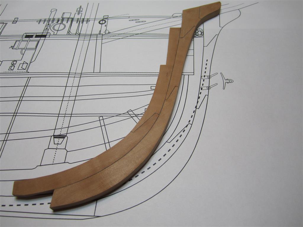
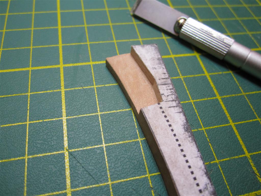
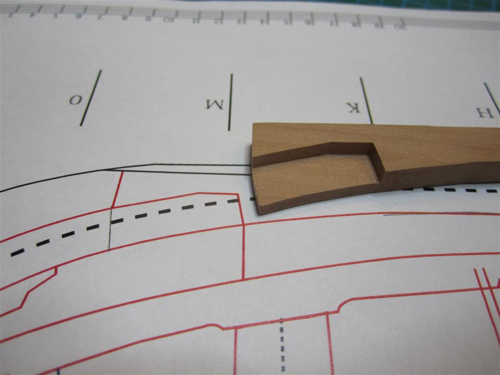
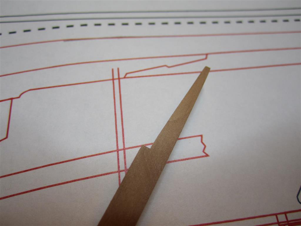
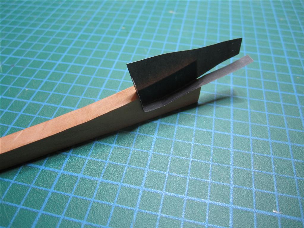
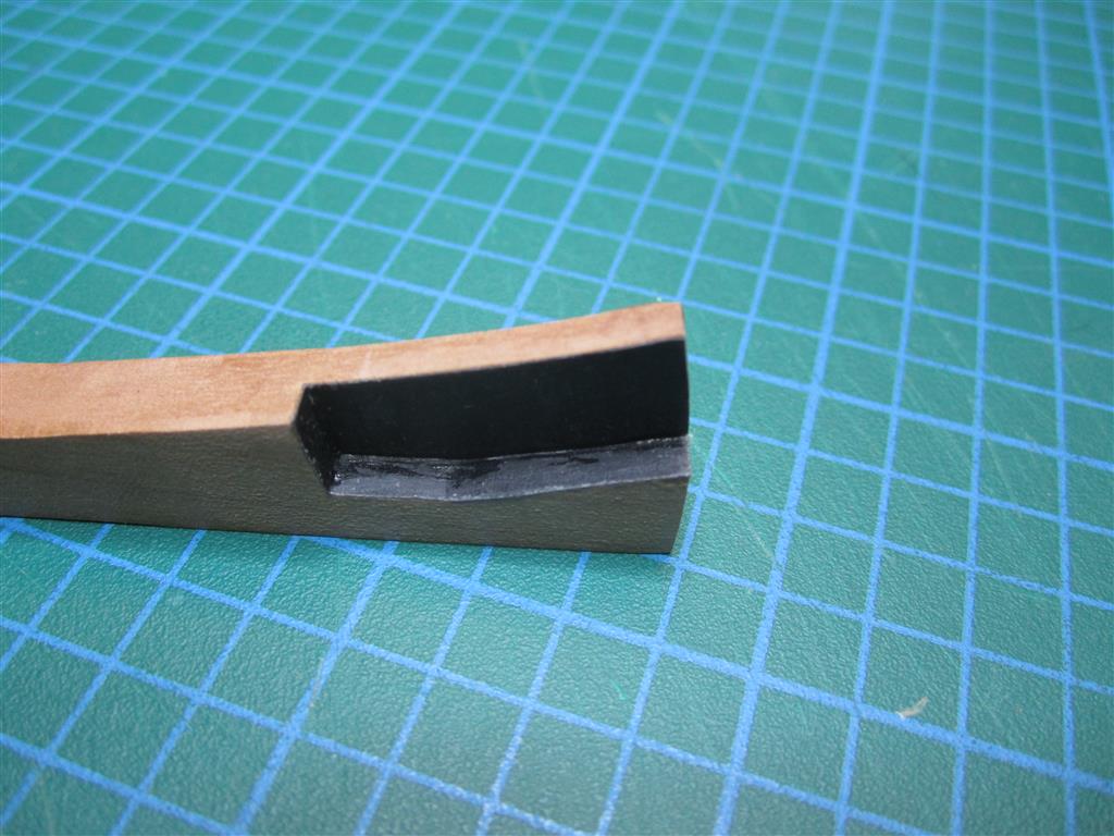
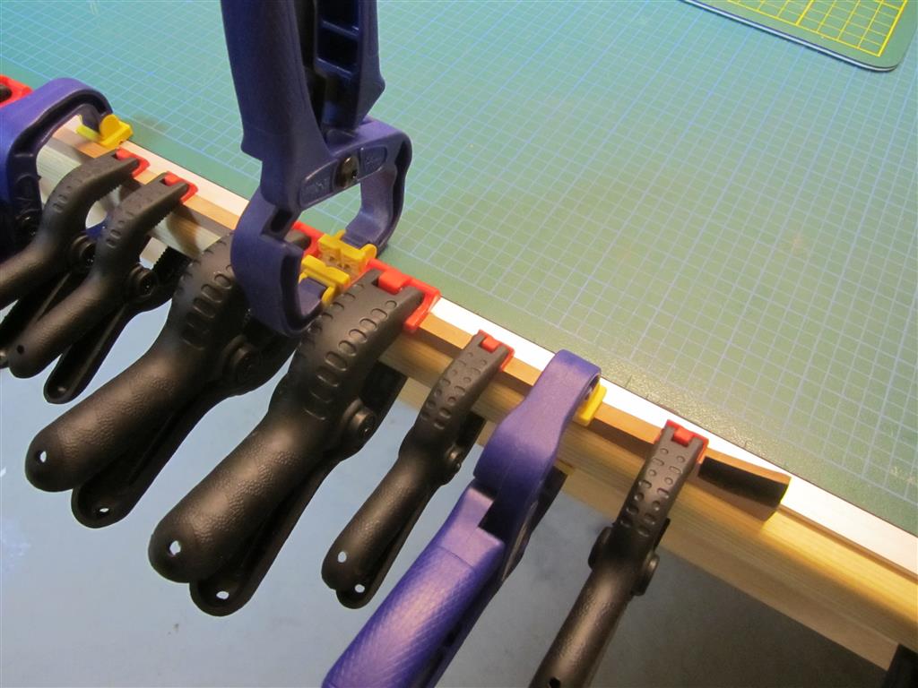
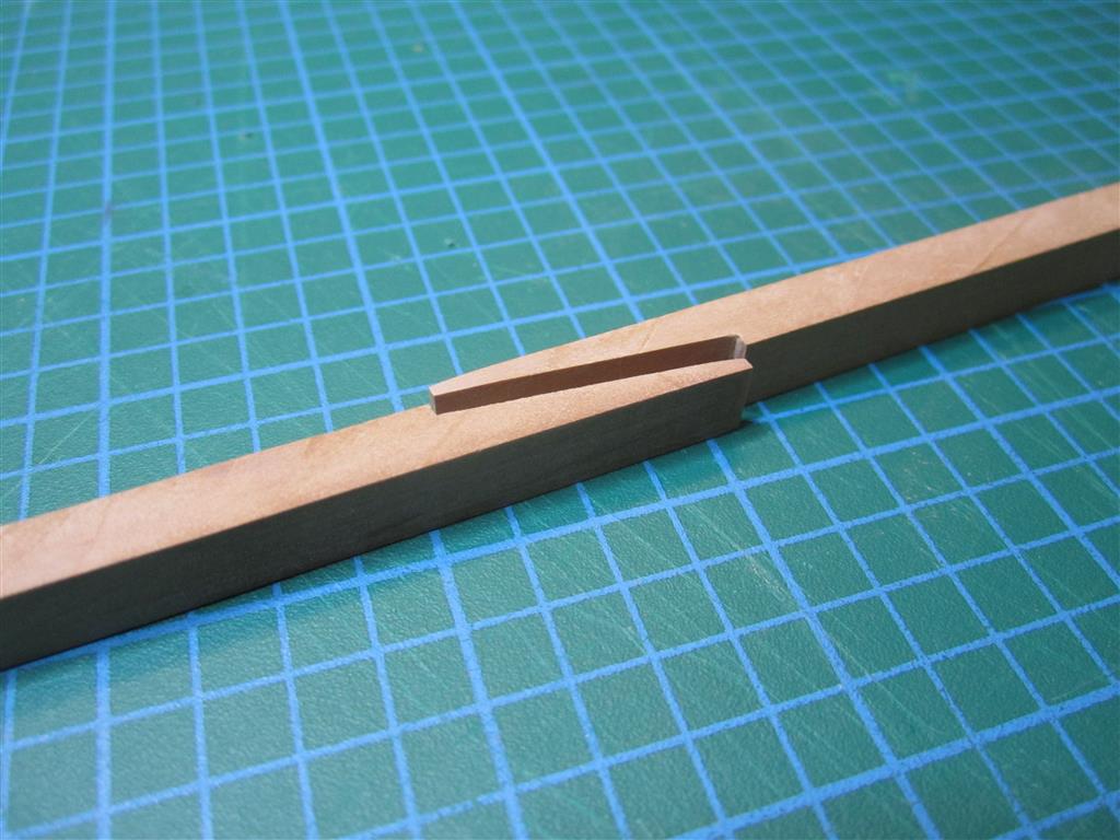
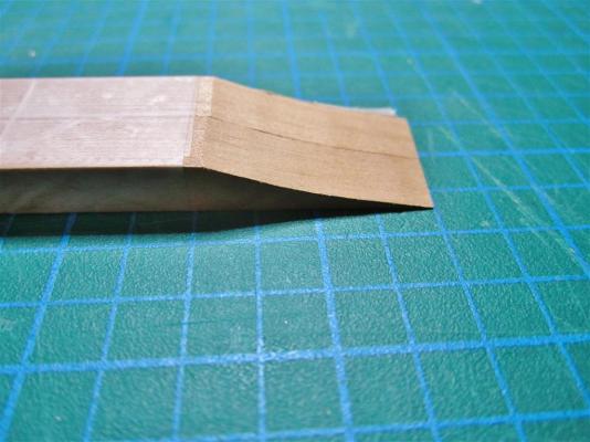
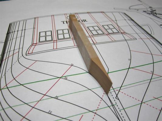
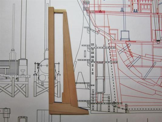
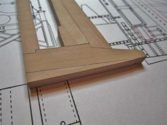
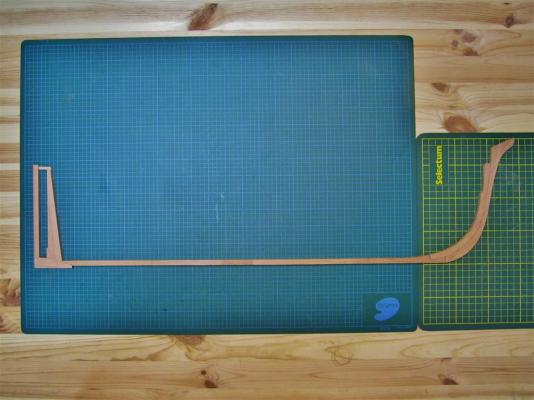
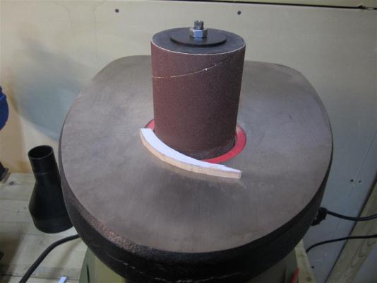
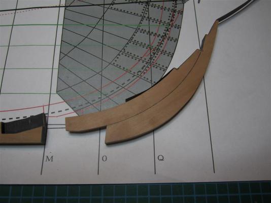
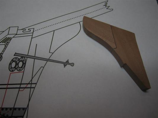
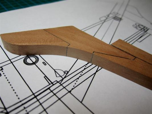
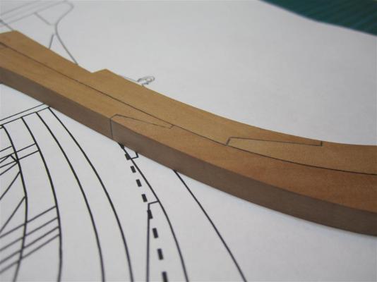
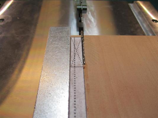
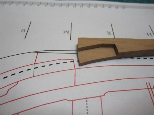
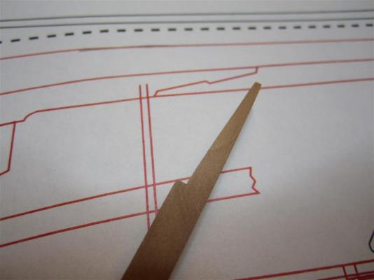
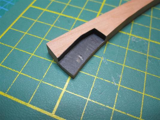
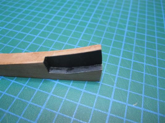
 OLIVER LANG’S STERN In February 1845, Oliver Lang, Master Shipwright at Woolwich, faced a daunting challenge. The Admiralty, under pressure from Parry, had decided to outfit HMS Erebus and Terror for auxiliary screw propulsion, powered by small passenger locomotives. Screw propulsion was in its infancy and contemporary designs, based on patents filed by Francis Pettit Smith and others, called for the placement of the propeller opening in the deadwood of a steam powered vessel (Bourne 1855:28). However, applying such a modification to polar vessels would critically weaken the stern, and Lang knew from the Terror’s first arctic expedition that even the most robust sternpost was severely vulnerable when overwintering in sea ice. How could he protect the ship’s stern from the pack when a gaping hole had to be cut in the deadwood for the propeller? His solution appears in a plan dated March 17th, 1845, which was subsequently transcribed onto the 1836/37 profile plan for HMS Terror. Instead of altering the ship’s existing stern, Lang simply extended the stern of the ship aft by adding a new keel section, onto which a new rudderpost and aperture for the propeller were attached. The 1836/37 plans seem to show that Terror’s original sternpost had been modified for Back’s voyage, but the 1845 annotations clearly indicate that Lang reconstructed it to the same configuration used in Terror’s original design (alternately, it is possible that Terror’s stern was not modified in 1836 as planned). Lang’s 1845 design called for a triangular piece of wood to be bolted to the original sternpost, creating a vertical face for the propeller aperture. The new rudderpost and the angled fitting were both tenoned into the keel extension, as indicated by the presence of horizontal bolts on a contemporary model of the design. The entire structure was then bolted to a massive u-shaped “staple knee”, made from 3.5 inch thick iron, which was the same length as the propeller opening. Lang next turned to the problem of protecting the new rudderpost and propeller aperture from ice damage. He settled on a well system which could be used to ship and unship the propeller, similar to a design patented by Joseph Taylor in 1838 (Bourne 1855:32). However, Lang’s system included a new innovation; when the propeller was unshipped, the well would be filled with a series of stacking wooden and steel chocks. The chocks were shaped to match the dimensions of the new rudder post and deadwood and would completely fill the well, thus reinforcing the rudderpost against forces exerted by the ice. Taylor’s patent described that the propeller could be shipped via “vertical grooves cut in the true and false stern posts … in which frame the propeller is placed” (Bourne 1855:32). However, the use of reinforcing chocks required that this system be modified. Lang replaced the grooves in the stern and false stern with robust iron rails which themselves had a vertical slot running much of their length. The protruding rails were necessary to secure the chocks in the propeller well and needed to be very strong to endure the pressures of pack ice (I’ll present more on the configuration of this rail system and the propeller in a subsequent post). While we may never know how Lang’s chock system faired after two years in the grinding pack off King William Island, we can surmise that it must have worked relatively well because the Terror survived its first winter at Beechey Island in sailing condition. Further, we know that the same chock system was installed on the Intrepid and Pioneer (Anonymous 1850:8), steam tenders used in the Franklin search effort, and that both ships survived multiple winters in sea ice before being abandoned in relatively seaworthy condition. Scantlings for Terror’s Sternpost and Rudderpost Sternpost Sided At Head = 13 and ½ inches At Heel = 10 and ¾ inches Moulded depth = 17 and ½ inches Rudderpost Sided At Head = 13 and ½ inches At Heel = 10 and ¾ inches Moulded depth = 13 and ½ inches References: Anonymous 1850 Naval Intelligence — The Arctic Expedition. The Times. Monday , 6th May, pg 8. Bourne, John 1855 A Treatise on the Screw Propeller with Various Suggestions for Improvement. Longman, Brown, Green, and Longmans, London. Cut stern pieces prior to assembly. Assembled stern architecture (significant iron work has yet to be installed, and the temporary basswood piece is to provide rigidity until the propeller well is completed). Detail of keel piece and opening for the staple knee. Aft view of the unique rudderpost joint with the keel. Another view of Lang's design. Sanding two of the sternpost bolsters to match the aft station (the bolsters provide width needed for the propeller well). Detail after sanding. Comparing the bolster to the body plan. Completed rudderpost and sternpost bolsters. Two of the bolsters in place, showing how they add width to the stern to accommodate the propeller well (these aren't glued and cannot be until the bulkhead is attached). Current progress on the stern, keel, and stem.
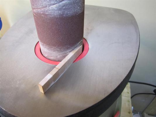


- 346 replies
-
- 21
-

-
- terror
- polar exploration
- (and 2 more)
-
A great start for the Mark II. I'm glad to see you salvaged some of the great work you did on the MARK I version.
-
Beautiful work, Ed. She's going to be sleek when planked....
-
I'm really looking forward to your adventures with pewter. I need to make a "gunmetal" propeller soon, so I'll be taking notes!
-
This looks very interesting. Great start with the turned pieces! Interesting error in the pintles - working with multiple drafts of the same boat can be frustrating and illuminating all at the same time.
-
Mark, Michael- Thanks for the words of encouragement. Much appreciated!
-
TERROR’S STURDY STEM Completed bow timbers compared to sheet plans (note that the fore edge hasn't yet been trimmed). Nowhere is the strength of HMS Terror’s frame more evident than in her bow architecture. Already stoutly built as a bomb vessel, Terror’s 1836/1837 plans indicate that the bow was significantly altered for conversion to polar service. The 1836 deck plans show that her stem was sided 12 and ½ inches, the same as her keel, but it was much thicker/deeper than normal. In fact, its moulded depth was greater than a vessel three times her tonnage (see scantlings below). This robustness was also transferred to her apron, which was consistent in size with that used on a 36 gun frigate. Terror’s external bow timbers were also modified in 1836; all ornamentation pieces were removed, as were the cheeks, forefoot, bobstay piece, gammoning, and lacing. In their place, a very robust and simplified architecture was installed which consisted of a gripe, stem piece, main piece, and a short chock to support the bowsprit. Again, these pieces were very robustly built, and were sided the same as the keel, diminishing to only 10 inches at the fore edge. Aft of these bow timbers, the stemson was similarly solid, sided the same as the stem and just as thick. However, in 1836, the stemson itself was reinforced by massive oak chocks the same width as the stem, but this time up to 16 inches thick. At the position of the third waterline, this effectively created a single massive block of wood, 12 and ½ inches wide and extending from the stem piece more than eight feet aft. Indeed, it was strengthening like this that permitted Crozier to use the Terror as an icebreaker during the Antarctic voyage of 1839 (Ross 1847:147). Scantlings for Terror’s Stem and Apron: Stem Sided: At Head (same as the keel) = 12 and ½ inches At the Heel = 12 and ½ inches (larger than vessels of her size) Number of pieces = 2 Moulded Depth = 16 inches (larger than 36 gun frigate) Scarphs in length = 3 feet 9 inches (boxing) and 3 feet (upper) Lips of the scarphs = 3 inches (consistent with standards for a 12 and ½ inch sided keel) Bolts = 8 (consistent with 76 gun vessel, standard for bomb vessels) Bolt diameters = 1 and 1/8 inches (consistent with 36 and 74 gun vessels, standard for bomb vessels) Apron (false stem) Sided (same as the stem) = 12 and ½ inches Moulded depth = 9 inches (consistent with 36 gun frigate) Moulded depth diminishing to the head = 7 inches Scantlings for Terror’s Knee of the Head: Sided (all pieces): Aft part of knee (same as the stem) = 12 and ½ inches Diminishing to the fore = 10 inches Lower scarph in length = 2 feet and 1 inch Upper scarph in length = 4 feet 2 inches References: Ross, Sir James Clark 1847 A Voyage of Discovery and Research in the Southern and Antarctic Regions, During the Years 1839-1843: Volume I. John Murray, London. Sanding the lower stem piece to size. Shaping the upper stem piece. Finished stem and gripe (vellum simulates tarred flannel used on a real ship). Finished main piece and chock to support bowsprit. Detail of scarph joints. Main piece joined to stem piece. Port side view (note that the fore edge has not yet been shaped).


- 346 replies
-
- 10
-
-
- terror
- polar exploration
- (and 2 more)
-
brilliant job on the pumps!
-
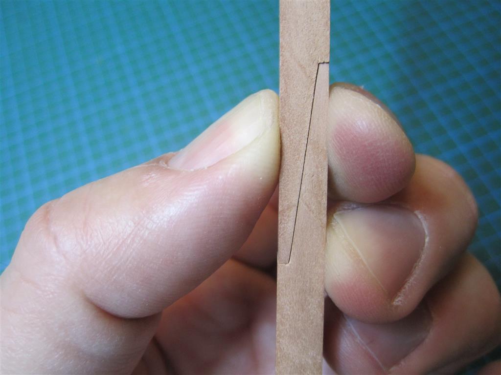
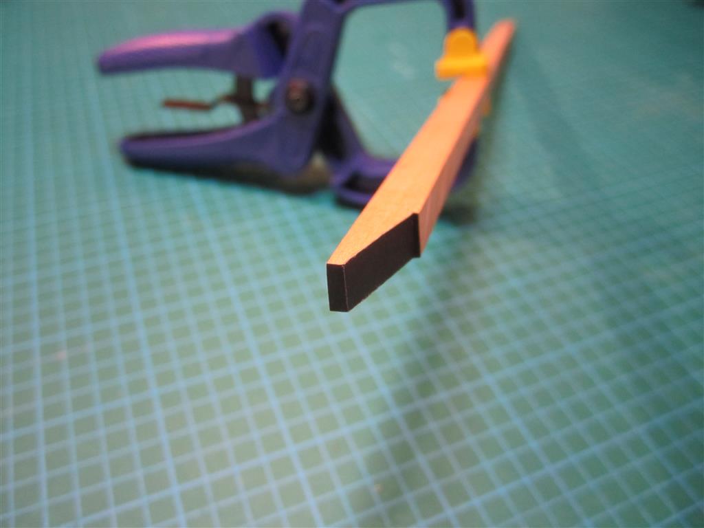
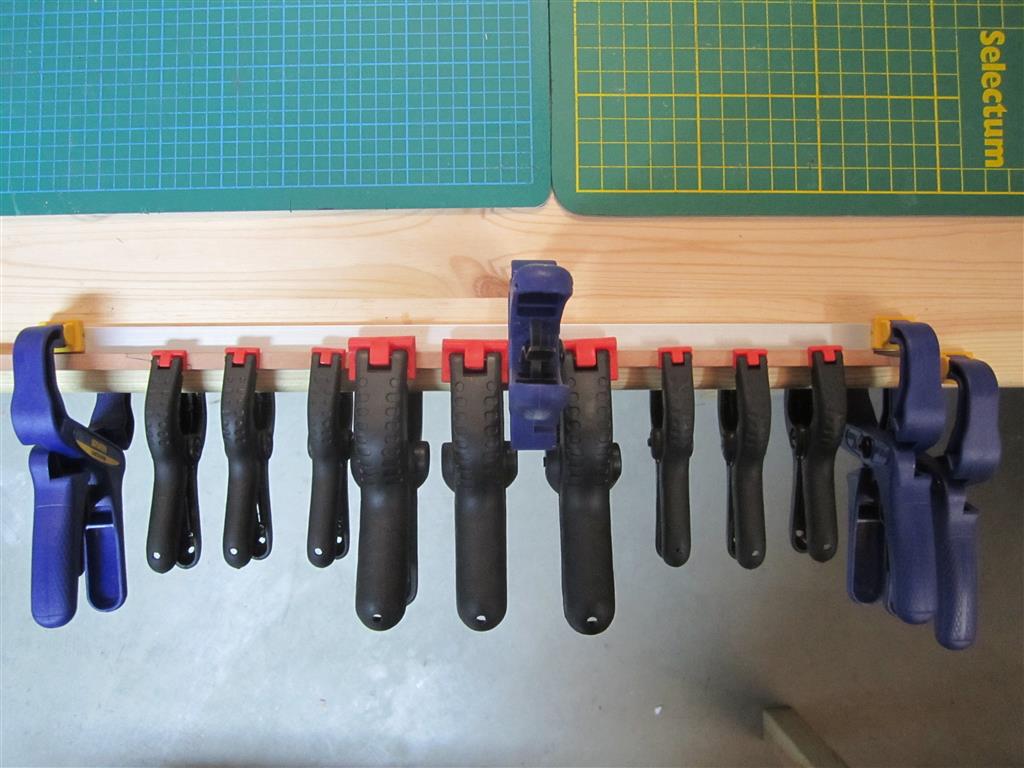
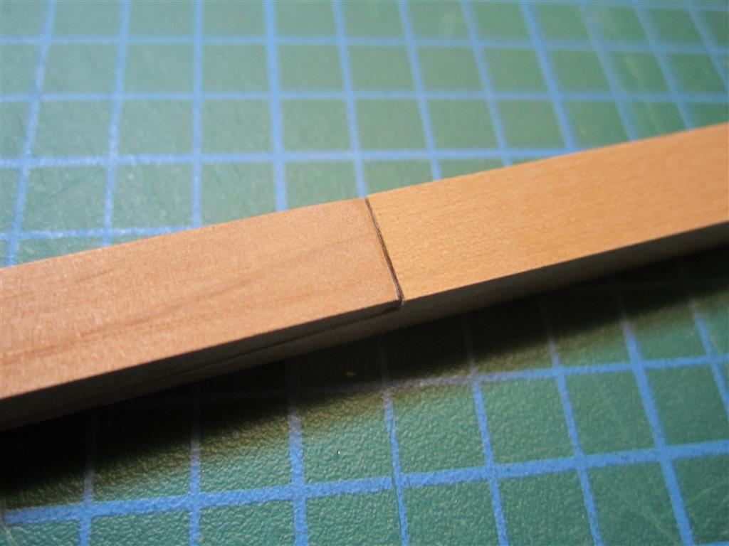
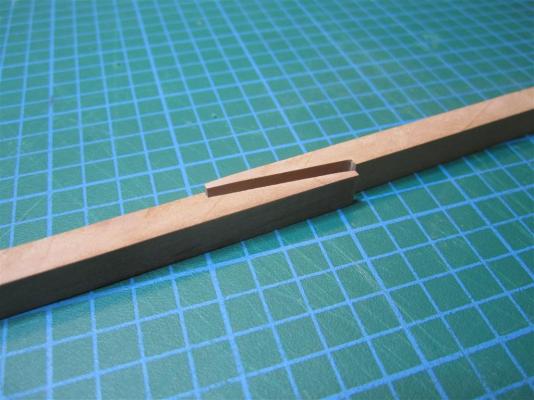
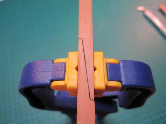
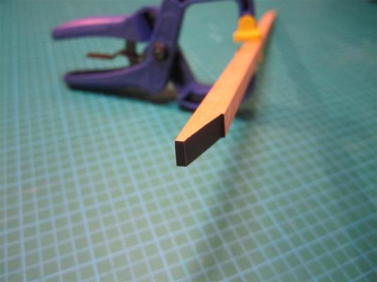
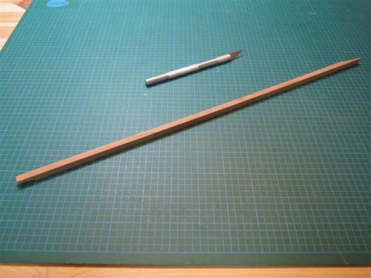
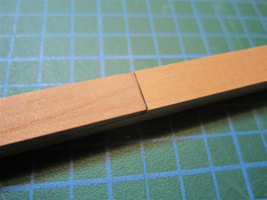
BOXING SCARPH This section represents the final piece of the keel for my model and was the most difficult to make. I temporarily glued a paper template to the swiss pear blank, then I cut it out with a mini table saw and scroll saw. I sanded the piece to the precise dimensions using a spindle sander and modeler’s files. The box scarph was carved by hand using a small chisel, and then scraped flat with a razor blade. Like the rest of the keel, I lined the boxing with vellum to simulate tarred flannel. Cutting the aft part of the keel section. Chiseling out the box scarph. Finished scarph compared to plans. Plain scarph at aft of keel section. Gluing the vellum in place. Vellum trimmed to fit. Finished box scarph. Section glued to the rest of keel.


- 346 replies
-
- 8
-
-
- terror
- polar exploration
- (and 2 more)
-
Hi Alistair, Thanks for the nice comment. I have read Barrow's Boys. It's a very good book and he does an excellent job of describing the context of the program of exploration. I haven't referenced it yet because my focus is really on the ship and her systems and not directly on the expeditions it was involved in. But it is a great read and certainly anyone interested should look at it. In fact, I recommend they read it prior to any of the first-hand accounts by the expedition commanders themselves! Regards, E&T
- 346 replies
-
- 1
-
-
- terror
- polar exploration
- (and 2 more)
-
Thanks Druxey, that means a lot coming from someone as knowledgeable as you. A book? It's early days for that yet.
-
Can I have copies of your plans? Hello Folks, Over the past six months I've had great feedback on my topic here on MSW and on my blog. The chance to interact with modelers of such ability is a real privilege. I've also received a lot of requests for high resolution copies of my plans. I’m extremely happy that people want to build the Terror, which I consider to be one of the world’s greatest exploration vessels. She deserves the attention. I do plan to release copies of the plans at some point (and yes, I do intend to make full masting and rigging plans for her). However, I'm still at the beginning of my project, and my plans are not proven by construction. I know they will require some modification as I build. I don't want to send them out with errors, as that would just make more work for people. When I'm finished my build and the plans are complete, I'll make them available as a set. And I'll post it here on these boards so you are the first to know. Does that sound reasonable? I hope everyone understands! E&T
- 346 replies
-
- 4
-
-
- terror
- polar exploration
- (and 2 more)
-
Many thanks for the encouraging words. They are really appreciated. More soon (I hope)!
-
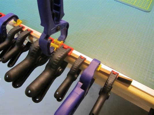
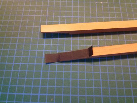
Laying the Keel In September, 1812, around the same time that Napoleon was entering a deserted Moscow on his push to the Kremlin, HMS Terror’s keel was being laid down in Topsham shipyard on the River Exe. Her keel construction exposes much about her design; it incorporated some traits of a merchant vessel of her size (ca. 325 tons), but was generally overbuilt to the standards of much larger ships. The Vesuvius class bomb ships were based on the lines of merchant vessels (Ware 1994:64), but with a much stronger frame to withstand the punishing recoil of the mortars. Sir Henry Peake, Terror’s designer, achieved this sturdiness by incorporating some aspects typically reserved for 36 gun frigates (ca. 1000 tons) and even 74 gun third rates (ca. 1500 tons). Scantlings for Terror’s Keel: Sided = 12 and 1/2 inches (consistent with merchant vessel of the same tonnage) Depth of keel = 1 foot 3 inches (consistent with a small fifth rate frigate) Number of pieces = 4 (consistent with merchant vessel of the same tonnage) Scarphs in length = 4 feet (consistent with 36 gun frigate) Scarph type = plain (with tables) Lips of the scarphs = 3 inches (consistent with standards for a 12 ½ inch sided keel) Bolts = 8 (consistent with 76 gun vessel, standard for bomb vessels) Bolt diameters = 1 and 1/8 inches (consistent with 36 and 74 gun vessels, standard for bomb vessels) Depth of False keel = 7 inches (thicker than a 74 gun vessel) The keel of my Terror model is made from swiss pear, with black dyed paper vellum used to simulate the tarred flannel used to line the scarphs in a real vessel. I use acid and lignin free vellum which is both colour stable and dimensionally stable, and takes wood glue very well. As in many model ships, my scarphs aren’t tabled as they won’t be visible when glued. References: Ware, Chris. 1994 The Bomb Vessel: Shore Bombardment Ships of the Age of Sail. Naval Institute Press, Annapolis. Vertical keel scarphs prior to gluing. Dry fit of keel scarph. Vellum glued to scarph. Trimmed vellum on horizontal scarph (stern). Keel scarph with vellum. Profile of scarph with vellum. Gluing the keel sections. Finished keel section.


- 346 replies
-
- 15
-
-
- terror
- polar exploration
- (and 2 more)
-
Interesting ship and a great scale. Very nice work so far. Thanks for posting this - I'll follow along.
-
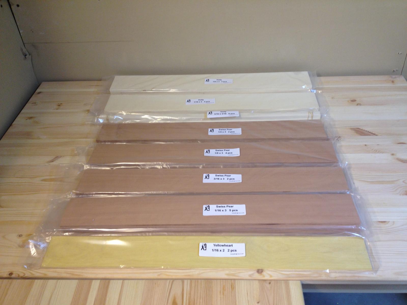
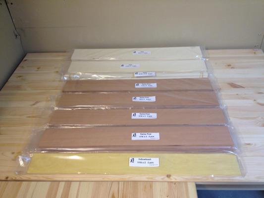
There has been little progress on my build over the last several weeks due to demands at work and with the holidays, but I just had to post an image of an (early) Christmas gift. My stock of building material from HobbyMill arrived a few weeks ago! Swiss pear, holly, and yellow heart, all milled and finished to Jeff’s exacting standards. It was a real pleasure dealing with him and the wood is top quality. In fact, the swiss pear is so nice that I’m starting to rethink my plan to dye it…
- 346 replies
-
- 2
-
-
- terror
- polar exploration
- (and 2 more)
-
Wow - she's going to be huge! What a difference from the little Corel models we built. Beautiful work Antony!
-
Thanks Antony! if I can match half the skill displayed in your current Victory build, I'll be very happy!
-
Hi Druxy, In fact, I'm relieved to see you write this about the rudder colour. I was trying to be objective about the colour scheme in all the paintings - just presenting the data. But I've tried a few mock-ups and a white rudder or a black rudder with white trim just looks goofy against a black hull. As I mentioned, the weight of evidence suggests a black rudder. I know that vessels like the Granado had white rudders, but here the ship's hull was painted white as well. I've looked all over for information about standard RN paint schemes of the era but have found only a few references. It seems in general the rudder colour matched the hull colour, but I have no solid reference to cite in this regard. E&T
-
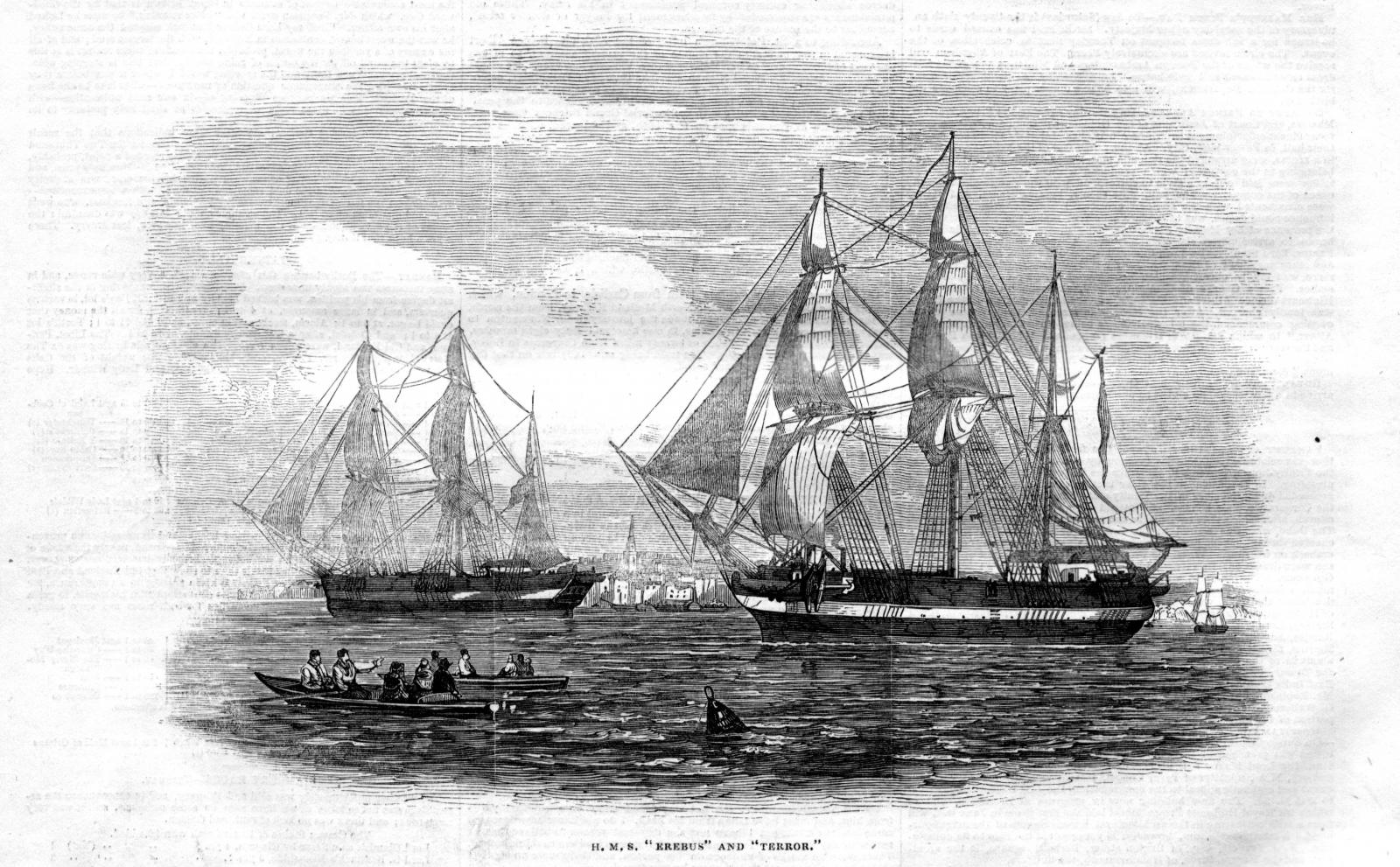
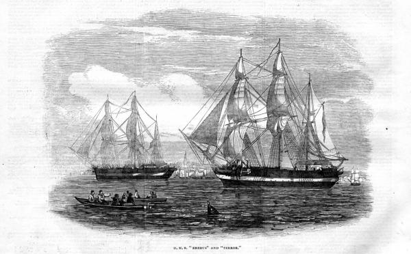
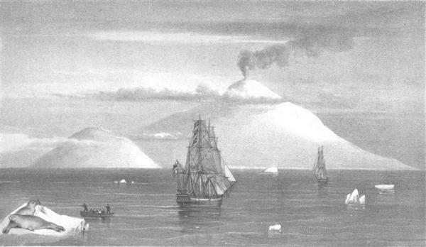
HOISTING TERROR’S COLOURS HMS Terror’s paint scheme is considered to be well known. Richard Cyriax, who produced the most authoritative work on Franklin’s last expedition, states: “Both ships were flush-decked, and had black hulls, white masts, and yellow weather works...” (Cyriax 1997:39). This passage has long been interpreted by subsequent researchers to mean that the ships had a yellow stripe along their outside hull (e.g. Parks Canada, Canadian Geographic, and published work too numerous to list here). Cyriax based this description not on a primary source, but on a popular work by his friend, Rupert T. Gould (1928:112); unfortunately Gould appears to have misinterpreted the primary source material. Gould’s information came from a remarkable parliamentary record, which documents an Admiralty investigation into two ships spotted trapped in an iceberg off the coast of Newfoundland in 1851 (Inglis 1852). The investigation focused on comparing the eyewitness testimony about the iceberg ships to the firsthand knowledge of the shipwrights who worked on Erebus and Terror. While the Admiralty determined that the iceberg ships could not be Franklin’s vessels (the size difference between the ships was too large and they were not barque-rigged ), the report contains critical primary information on the paint scheme of the Erebus and Terror from Oliver Lang, the master shipwright responsible for the 1845 refit of the vessels. The correspondence between Lang and the Admiralty is worth quoting here in its entirety (Inglis 1852:18): Admiralty, 17 April 1852. Sir, I am commanded by my Lords Commissioners of the Admiralty to desire you to call upon the officers of the yard under your superintendence to report how Sir John Franklin's ships, the " Erebus" and " Terror," were painted when they sailed. I am &c. (signed) J. H. Hay, pro Secretary. Commodore Superintendent Eden, Woolwich. Woolwich Yard, 17 April 1852. Sir, With reference to their Lordships' letter of this day's date, we beg to acquaint you, that Sir John Franklin's ships, the " Erebus " and " Terror," were painted when they sailed, black on the outside, and weather works inside yellow. We are, &c. (signed) O. Lang, Master Shipwright Further information about the colour of the masts was also requested from Lang and appears below (Inglis 1852:35). Admiralty, 2 June 1852. Commodore Superintendent at Woolwich, Referring to your communication of the 17th April last, upon the subject of painting the " Erebus" and "'Terror," my Lords desire that you will state for their information how their lower masts were painted. By command of their Lordships. (signed) W. A. B. Hamilton. Woolwich Yard, 2 June 1852. Sir, Agreeably to your minute on Captain Hamilton's letter of yesterday, we have to acquaint you that the lower masts of the "Erebus" and "Terror" were painted white when they left this port. We are, &c. (signed) O. Lang, Master Shipwright.. H. Chatfteld, Assistant ditto.' (Mr. Peake sick.) The Commodore Superintendent. Submitted for the information of their Lordships. Henry Eden, Commodore Superintendent. The Secretary of the Admiralty Lang’s choice of words in the first correspondence appears to be the source of the enduring discrepancy regarding the ships’ paint schemes. It seems Gould, followed by Cyriax, and then myriad others, interpreted the phrase “weather works inside yellow” to mean a band of yellow on the outside hull of the vessel. Indeed, the “weather works”, or upper works of a ship, are those areas of the vessel above the waterline exposed to the weather, including the upper hull and bulwarks both inside towards the deck and outside on the hull. However, Lang specifically states that the “weather works inside “ were yellow, meaning that the inside bulwarks were painted yellow. He makes no mention of a stripe on the outside hull, although a solid paint scheme without a stripe would have been unusual for a Royal Navy vessel of the era. Thankfully, a watercolour painting by Owen Stanley, who accompanied the ships across the North Atlantic to Greenland in 1845, provides important primary evidence which dispels much ambiguity (see below). The painting shows conclusively that the Terror and Erebus had black hulls with a white stripe along the outside weather works. The painting indicates that the white stripe was contiguous with the chock channel and that it ascended the outside stern frame of the Erebus at an angle. Another watercolour, which may also be the work of Stanley (it is clearly based on his 1845 drawing), confirms these characteristics, and also shows the yellow painting on the inside bulwarks (note also the very rusted condition of the iron bow plating). This image also suggests that the white stripe extended forward around the knee of the ship. The presence of a single stripe along the hull, which extended around the knee of the ship and up the exterior stern frames, appears to be confirmed in other contemporary sketches by Stanley, Gore (also here), and Fitzjames, as well as by the Illustrated London News (which also confirms the white stripe on the outside stern frame, see below). A white stripe painted on the exterior weather works is entirely consistent with Royal Navy standards of the mid-19th century. Yellow and black striping, or the “Nelson Checker”, was common in the Royal Navy vessels up to about 1815. However, after ca. 1815, Royal Navy vessels began to adopt the black on white pattern first established by the American Navy around the turn of the 19th century. In fact, black hulls with white stripes remained the standard paint scheme of Royal Navy vessels well into the steam era (see Konstam 2010 for good summary). It therefore seems obvious, given all of the available data, that Erebus and Terror were painted with the standard white on black scheme of the era, which may explain why Lang didn’t deem it necessary to mention this standard attribute to the Admiralty. Most Royal Navy ships placed the white stripe over the gun ports above the waterline; when opened, the ports/lids created the “checker board” pattern. However, all contemporary images of the Franklin ships show that the white band corresponded with the solid chock channels grafted on to the ships. It is important to note that this paint scheme is different than that utilized during the 1839 Ross voyage, where the ships appear to have had two bands of white on the outside weather works. This watercolor of HMS Terror by Davis shows that one of the white stripes was contiguous with the chock channels, as in the 1845 expedition, while the other white stripe was a little lower, perhaps contiguous with the band of copper sheathing that extended below the chock channels for most of the ships' length at this time. The colour of the top, horizontal, surface of the channel is less certain, as the Stanley watercolours provide little detail in these areas. One of Stanley’s sketches (see here) seems to indicate that the tops of the channels were black, while another suggests they were potentially white (see here). However, the famous image from the Illustrated London News clearly shows that that the top of the channels were painted white (see image above). An image of the Terror beached on the Irish Coast in 1837 by Owen Stanley (see here) also shows that the tops of the channels may have been painted white (or at least a lighter colour), though how consistently the ships were painted on subsequent voyages is unknown. Since the paint scheme is ambiguous, I intend to try both versions on the model and choose whichever seems to fit better with the overall colour scheme of the ship. Similarly, contradictory information exists about the paint scheme on the rudder and transom of the ships. The 1845 watercolour by Owen Stanley seems to show that the transom and rudder were painted black, although the lighting effects on the painting suggest that those areas of the ships may simply be in shadow. Other contemporary sketches by Stanley and Graham Gore (also here) suggest that a lighter colour was painted on the stern window frames and on the entire transom of the ship, while the rudder remained black (perhaps with white trim?). The Illustrated London News image is slightly different (see above), showing a thinner arch of white surrounding the windows of the ship and a darkly painted rudder. Colour paintings of the Erebus and Terror produced for the Antarctic expedition by Davis (see also here) show that the entire transom was painted white and the rudder was black, again perhaps with white trim (although lighting might play a factor here as well). Interestingly, the Davis paintings also show detail of an arch-shaped feature surrounding the windows. Similarly, a sketch of the Terror from 1837, by Owen Stanley, indicates that the transom was painted completely white (Back 1838:400, see below). A water colour of the Terror on the same voyage by William Smyth also shows an all white transom, this time with a white rudder. HMS Erebus and Terror under sail . Note lighter colour of transom (Ross 1847a). On balance, the available sketches and paintings suggest that the transom was painted completely white, and that the window frames were as well. The rudder is more ambiguous, but again, the weight of evidence seems to indicate that it was painted black, perhaps with white trim (the Terror did have several separate trim pieces grafted to the aft margin of the rudder). I assume the black hull paint extended to the keel, as we know that HMS Terror and Erebus were not coppered below the waterline, as noted in The Times on 26th April, 1845: “The decks of the Erebus and Terror are constructed on the diagonal principle, and about twenty feet on each side of the bows has been cased with strong sheet iron. There is not any copper sheathing on either of the vessels, as no danger is to be apprehended from the attacks of shellfish or barnacles, the ice soon clearing them from encumbrances of that description.” (The Times, London, 26 April 1845) This is in contrast with the Illustrated London News image of the ships which appears to show a copper plated hull, which must be an error. One of the things I enjoy about ship modeling is that it is woodworking – often with very fine hardwoods. Like many ship modelers, I don’t want to cover beautiful wood with paint; instead, I intend to present the Terror’s historic paint scheme using minimally treated natural or dyed/stained wood finishes. My plan is to use dyed or stained Swiss pear for the keel, stem and stern timbers, and hull planking; holly for the transom, chock, and deck planking; and yellowheart for the inside bulwarks. I’ve order the material from Hobby Mill, all planed to exact scale thicknesses, which I will discuss in future posts. My wood arrives in early December; until then, I will keep cutting stations! References Cited: Gould, Rupert T. 1928 Oddities. Frederick A. Stokes Company, London . Inglis, R.H. 1852 Vessels in the North Atlantic. House of Common Parliamentary Papers, London. Konstam, A. 2010 Naval Miscellany. Osprey Publishing, Oxford. As always, for better images please see my blog!
- 346 replies
-
- 6
-
-
- terror
- polar exploration
- (and 2 more)
-
Thanks for the info Danny and Druxy - you guys know more about the vessels of the period than most historians (and I've corresponded with quite a few)!
-
Wonderful work. I'm learning a lot just by following. May I ask what is the width of deck planking on the Swan class sloops? You mentioned it is less than 8 inches, but I wonder what is the "average" width? I ask because the width of deck planks on HMS Terror is 7 inches (drawn from archaeological data), and that appears to be unusually small. They were also double fastened, which is also unusual (as you say, less than 8 inches typically received a single spike/treenail), but not for polar vessels.
-
Interesting project for an interesting institution. I'm following and enjoying it very much!
-
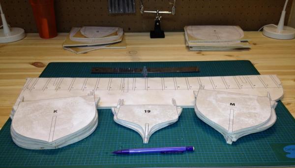
STATION UPDATE Over the past several weeks, another woodworking project has kept me away from HMS Terror. However, I’ve made a little progress on preparing the bulkheads for assembly. These are made simply enough; the plans are glued directly to the plywood board using spray adhesive and then cut out using a scroll saw with a fine blade. You can see from the picture that I’ve intentionally left a rough 1-2mm gap surrounding the plan outlines. It is impossible to cut the bulkheads accurately with the scroll saw, so they will be carefully reduced to the precise dimensions using a spindle sander and file. The midline slots will be cut with a coping saw and filed, again to ensure accuracy. If you look closely, you can see the shrewd eye of Crozier overlooking the outfitting of his ship (he’s 1:48 scale as well).
- 346 replies
-
- 8
-
-
- terror
- polar exploration
- (and 2 more)