DONATION DRIVE - SUPPORT MSW - DO YOUR PART TO KEEP THIS GREAT FORUM GOING!
×


Rick
-
Posts
43 -
Joined
-
Last visited
Content Type
Profiles
Forums
Gallery
Events
Everything posted by Rick
-
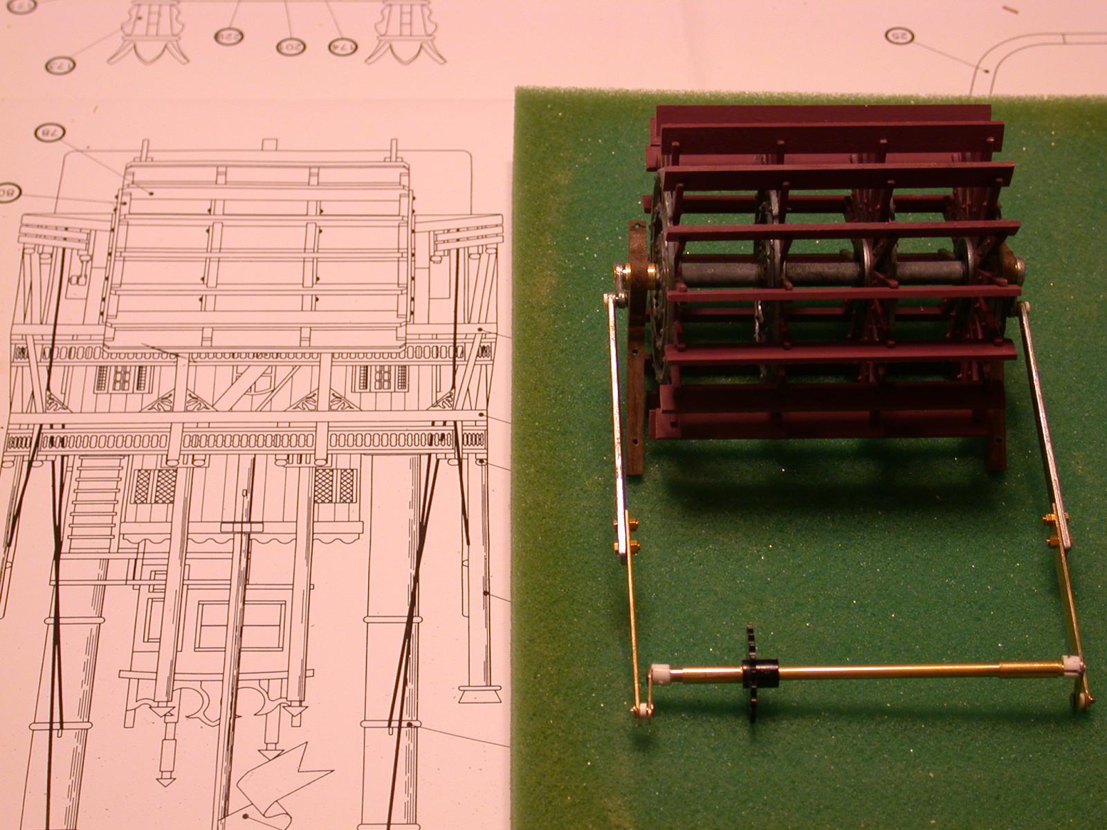
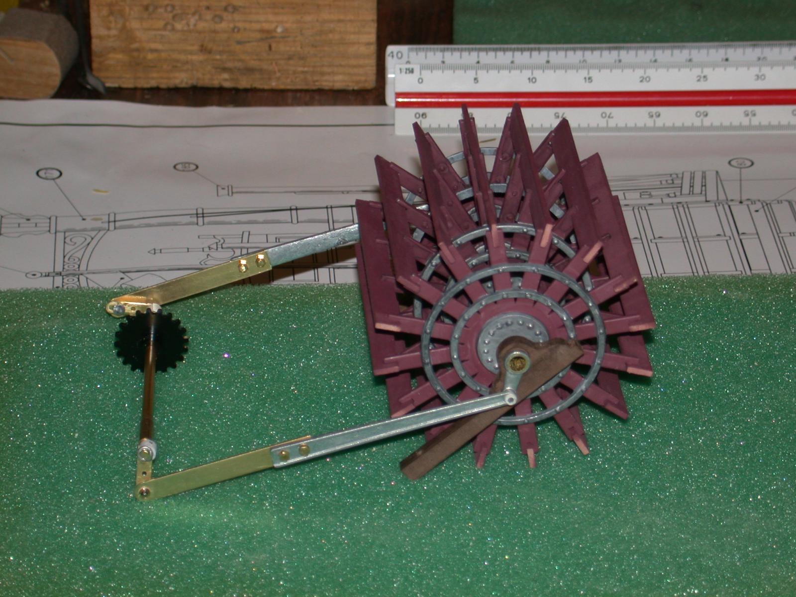
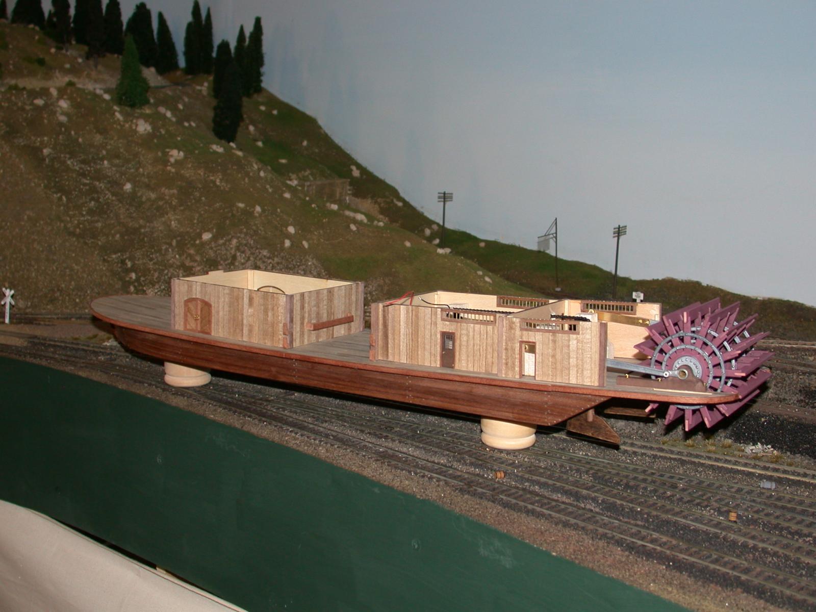
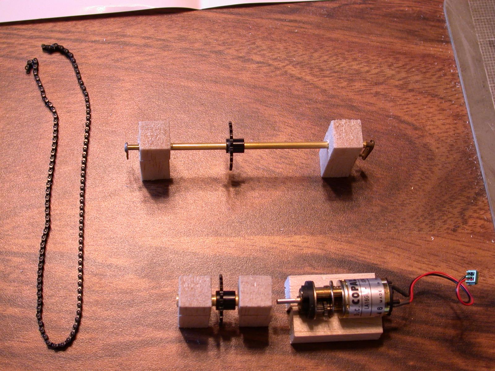
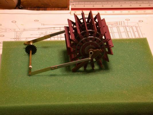
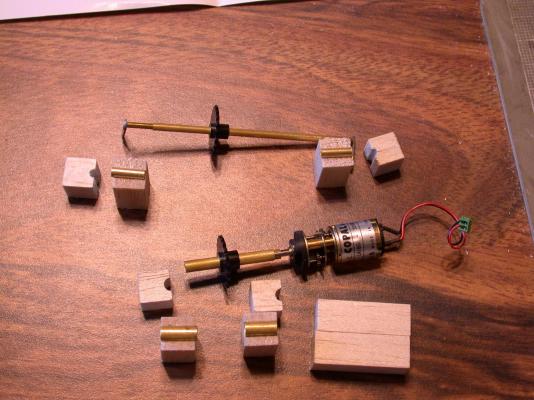
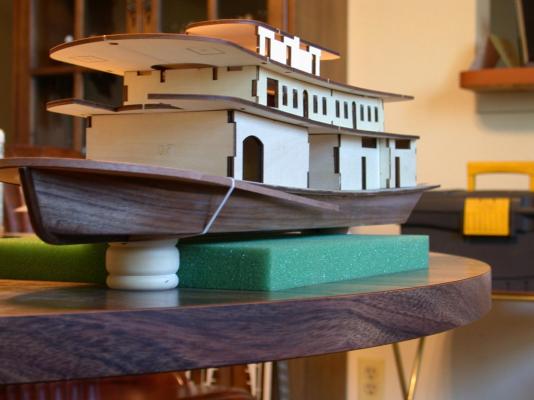
 Moving the paddlewheel by a steam engine was simple in the old days. Pressurized steam pushed and pulled a piston in the cylinder in a back and forth motion. To change into rotating motion, they devised what is called the cross-head guide at a joint in the piston rod to follow a crank that went around an axel, which was the paddlewheel. To make this work it took two pistons, rods, cranks setups to get past top dead center. The engineering of this is called quartering, in that the cranks had to be exactly 90 degree from each other when mounted on the axel. This had to be done in miniature on the KoM. It is not practical to use a small reciprocating steam engine. Instead, I had a nice, smooth running electric motor that ran in slow rotating motion. As shown in the previous post I made a new set of cranks and extended the rods to reach from the engine room to the paddlewheel. The tricky part is now I have four cranks that needed precise quartering. In short, a very flat surface (plate glass) and a true right angle (small machinist square) with good lighting and patience got the job done. Send me an email if you need a step by step setup of the procedure. The dimensions of the support bearings and the lengths of the rods also had to be very accurate. I used hat pins to temporarily anchor the positions of everything. Without the motor and chain attached I made subtle adjustments until every thing rotated smoothly by hand. The first three pictures show the crank and rod assembly outside of the boat. The first is comparison to the full size drawing, the second without a flash and the third with a flash. This last picture is the setup where I tested the paddlewheel the first time with power from my other hobby. I was able to get a reasonable video of the test and I am working on how to get an MP4 file in my next post. Hopefully very soon, Rick
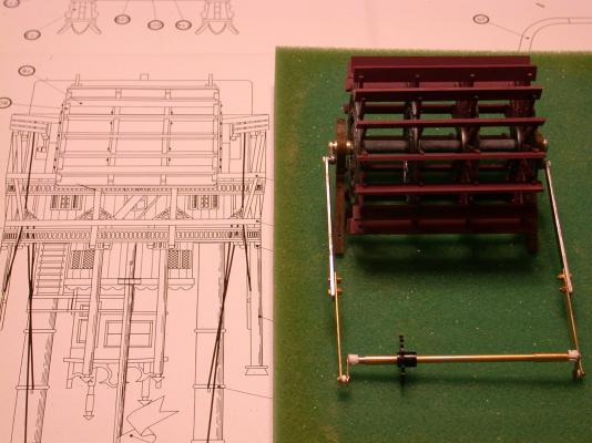

- 44 replies
-
- 3
-

-
- king of the mississippi
- artesania latina
- (and 2 more)
-
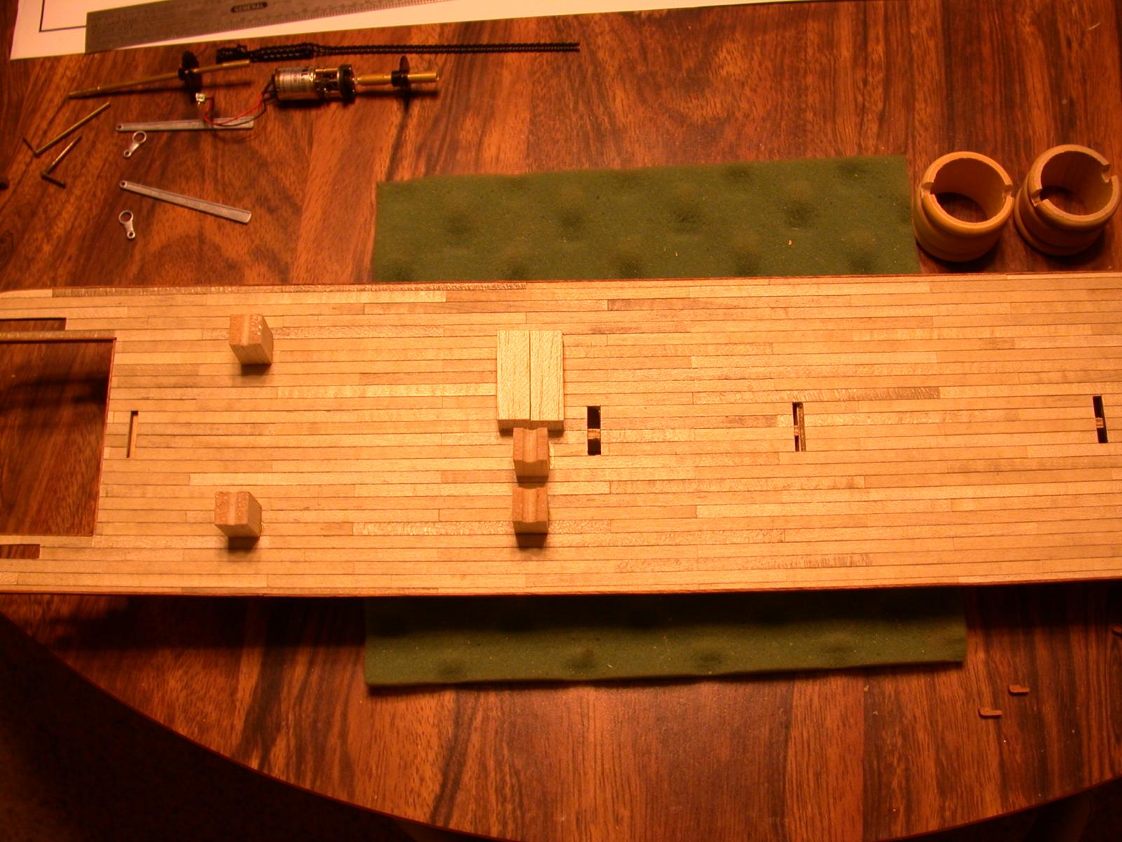
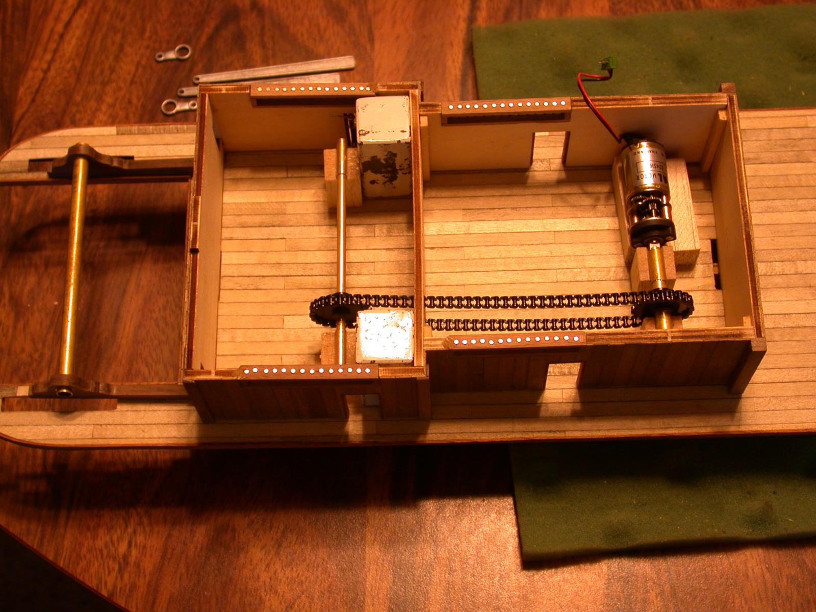
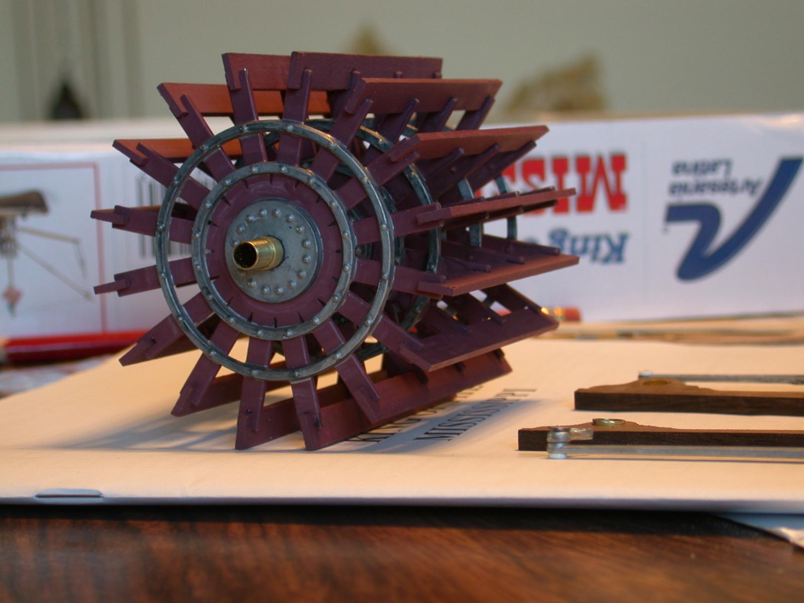
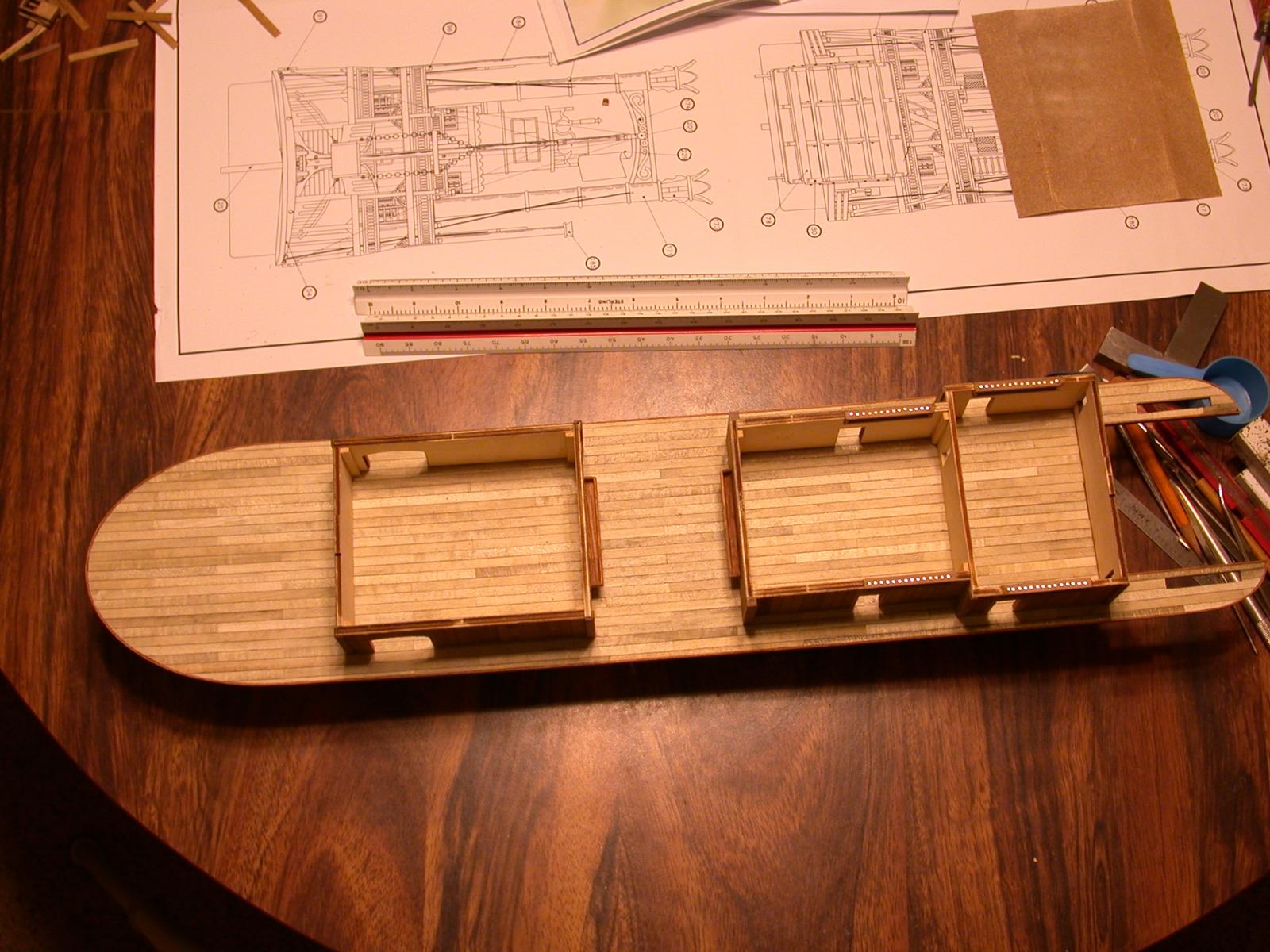
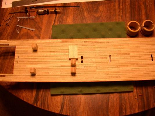
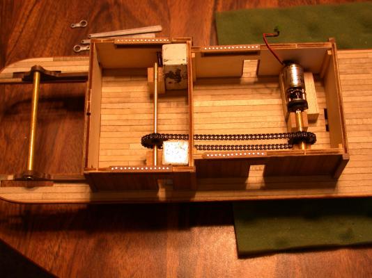
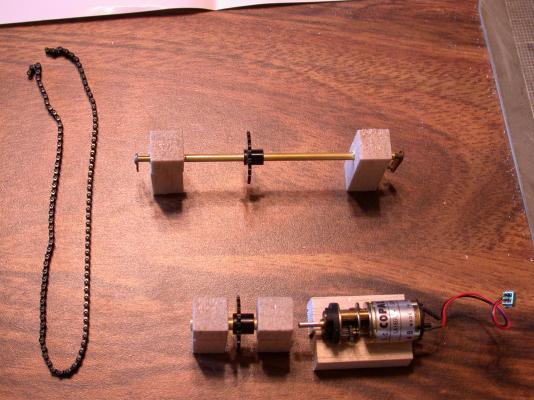
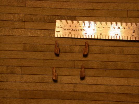
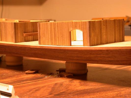
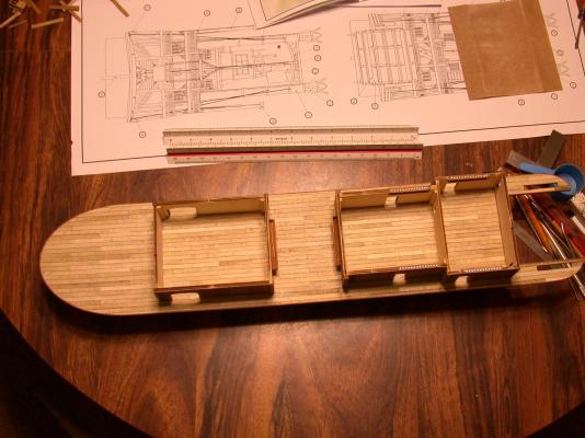
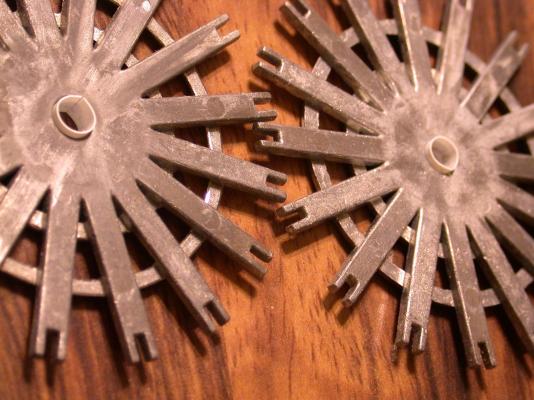
Some of you are waiting to see how it looks to motorize the sternwheeler kit from Artesania Latina. The previous post shows the drivetrain mechanism but now you need to see the modifications to the paddlewheel itself. Instead of the kit provided wood shaft I pressed the spoke castings on a larger diameter tube that fit snugly to the crank castings. AL did not make it easy. The spoke castings are about 0.020 inches too big and the crank casting are about 0.010 inch too small. Drilling out the crank very carefully to a tube size and making shims from 0.010 inch styrene made the spokes stay pretty good. I figured with four spokes and 16 paddle boards locking them in place should hold it firm to the axel tube. All this was laid out in the first photo with precise dimensions to position the wood blocks supporting the crank axel and the power axel. Seeing the pieces go into place was gratifying. The tube between the paddlewheel blocks is the same tube in the heart of the paddlewheel (the pictures are out of order). But this tube must spin freely in next size larger tube bushings pressed in the support blocks. Of course AL made it so it had to be drilled out first. This is a dry fit of the two axels. It is hard to see but the cranks will fit within about two millimeter clearance between the inside of the engine room walls. Thanks to Adrieke's suggestion I am making the rear wall of the engine room removable. Next time, final adjustments, Rick


- 44 replies
-
- 3
-
-
- king of the mississippi
- artesania latina
- (and 2 more)
-
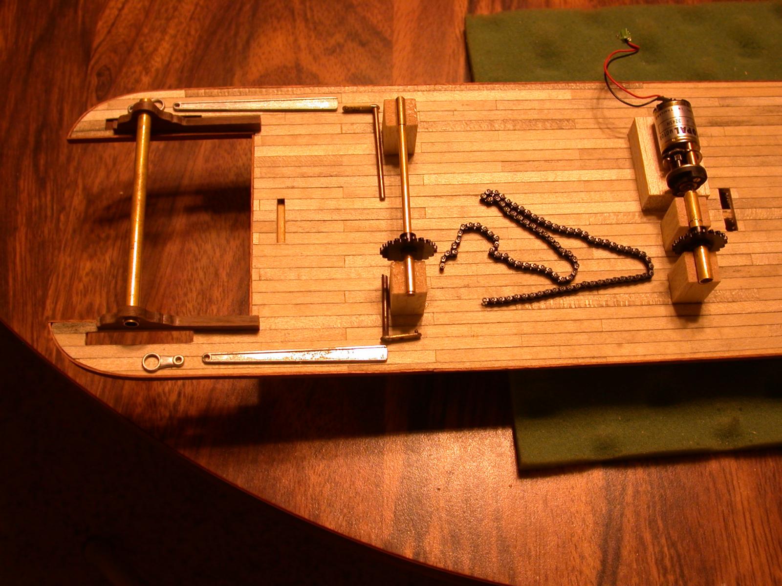
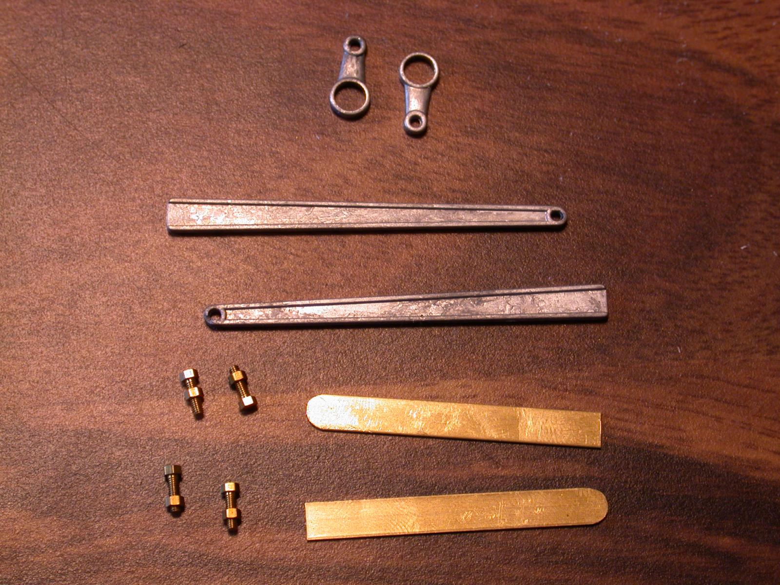
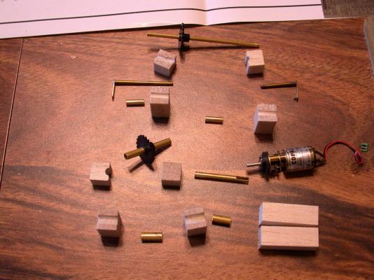
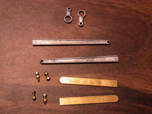
I am going to explain in this post my plan to motorize the paddlewheel on my KoM kit. Some of these items I had on hand but most are available at a good hardware store or hobby shop. I wouldn't have attempted this motorizing project if AL hadn't included the quality of castings that it did. The cranks and rods looked workable and I was impressed with the paddle wheel castings, which I call them "spokes". However many of the aspects of the KoM kit just fit with about 1 millimeter to spare. Plus many parts didn't fit but I figured I could drill them out or shim them in. Here in the first photo are the basic items for the drive completely unassembled. From the top is 1/8 inch diameter brass tube with a 7/8 inch diameter sprocket pressed onto the tube. The two thinner brass shafts have crank arms soldered on each end and fix nicely within the I/8 inch tube. Down from there are balsa wood blocks shaped to hold the two short tubes below them. The short tubes are the next size larger of the 1/8 inch tube and fix nicely as a sleeves or bushing. The slightly taller balsa wood blocks are the supports for the sprocket tube and bushings and hold them up half of the height of the engine room walls. Next in line is another sprocket on a larger tube. Next to it is the next size smaller tube with a slot cut in it. This was needed to couple to the flat tab on the small DC motor. It has a reduction gear built into it which results in about one revolution per second at about 1 volt. It was originally used in revolving display cases. On the bottom are larger bushings and support blocks the powered tube set. I start to assemble the components to show how they fit together. When fully assemble many pieces fit inside each other and are not visible. The third photo shows the assemblies are placed in a logical order to explain how the power gets to the paddlewheel. The plastic chain is part of the sprocket set that I ordered from Servocity.com. They deal with hobby robotics and RC stuff. The cranks and rods are critical parts to this project. The rods provided by AL just reach inside the walls from the paddlewheel. Barely good enough for a static model. I used the 1/4 inch brass strap and #72 hex head bolts to extend the rods. Measuring the effective length of the crank casting was one of the harder part of this project. In short, the paddlewheel motion will be driven by the short AL crank castings that will be connected by a pivoting pin to the AL rod which will be extended by bolting on brass straps which will be very accurately drilled for another pivoting pin to be attached to the brass cranks (they have to be exactly the same length of the cast cranks). The brass cranks are permanently fitted the small sprocket tube which will be driven the chain from the larger sprocket tube (the sprockets are the same outside diameter). The larger tube is coupled to the motor output shaft with little rotational slack but some sideways play to prevent binding. Clear as mud. :mellow: More, later, Rick
- 44 replies
-
- 1
-
-
- king of the mississippi
- artesania latina
- (and 2 more)
-
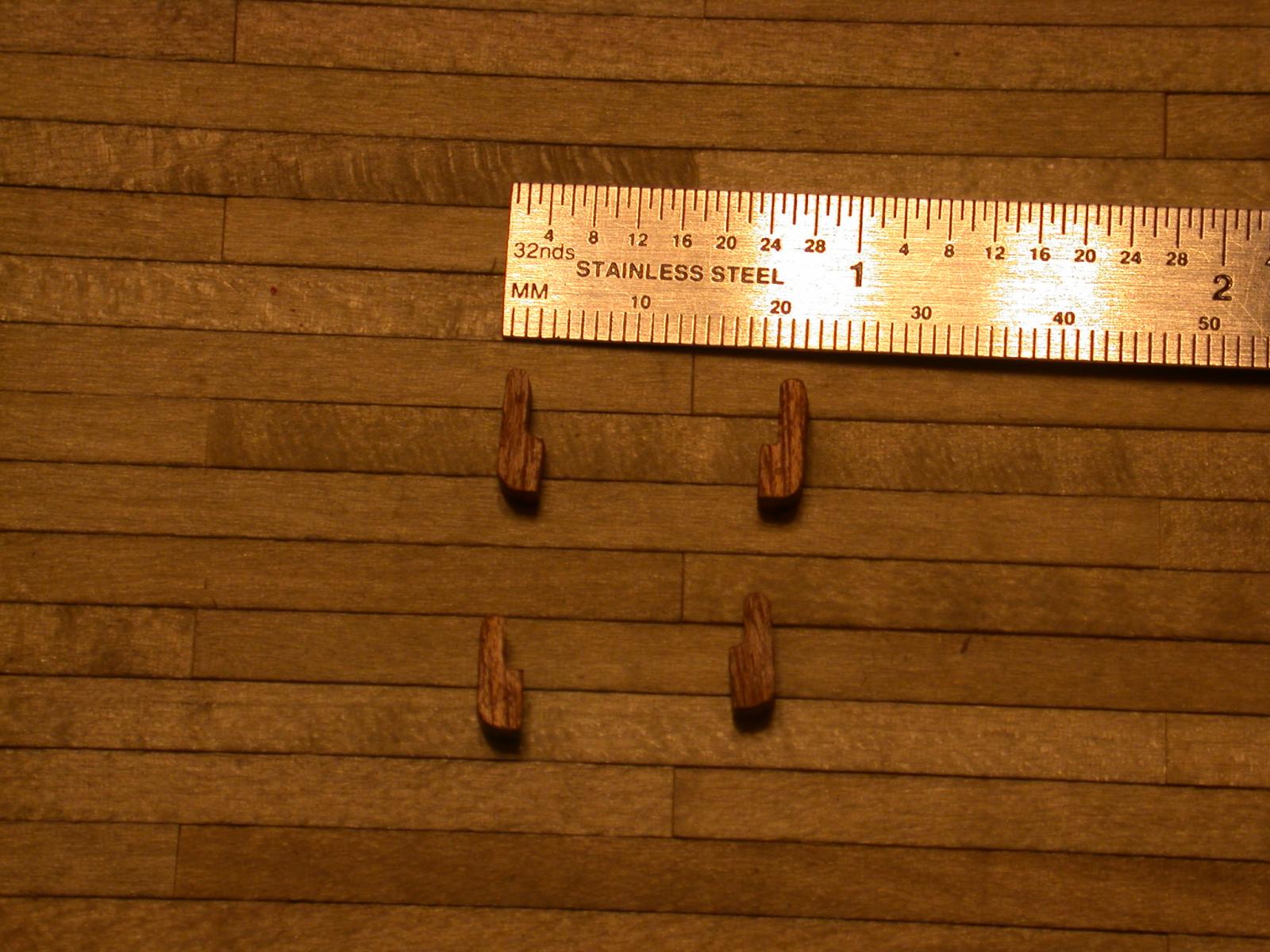
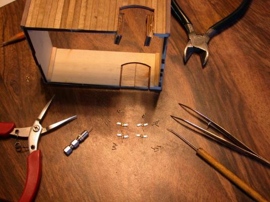
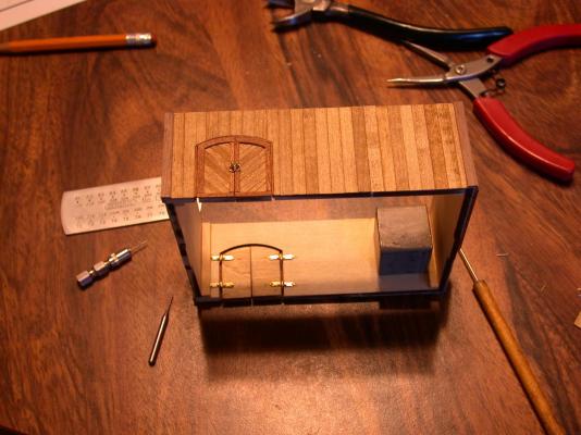
Thanks Adrieke, for your interest and assistance in building this boat. I'll keep trying to keep you all informed, one way or another. The doors on the boiler room are interesting and practical for a steamboat. I am sure they would of moved a lot of firewood through those doors as wells as a few large parts to repair the boilers. I am not to fond of the hinges; they remind me what might be found on doors in a dungeon. No offence to anyone who used them. It's my personal taste and I am the builder of this boat and I have my own specs for this project. Since I do want the doors to open and the hinges are designed to work, I decided to install them on the inside of the boiler room. It took some tricky sanding of the thickness of the plywood but I think they came out alright in appearance. I modified the supports for the boards that corral the horses and livestock in the stable. I tried a more rounded pattern knowing that horses tend to scratch themselves on anything sharp. Most people won't see this detail and as a matter of fact, I can't see it either. More stuff coming soon, Rick
- 44 replies
-
- 1
-
-
- king of the mississippi
- artesania latina
- (and 2 more)
-
Thanks in advance for all your help I just checked what toolbars I have on this browser. None of them have a check mark by them so they aren't visible. Under View/Toolbars I have listed: Microsoft Live Search Toolbar, Qwest Toolbar, Google Toolbar, ShopatHome.com Toolbar. I don't use them and if they are causing problems tell me how to delete them. Here is a test photo: Rick This message just bombed twice. I am not reinserting the photo but we can try that later - R.
-
I tried just now a shorter message with 3 photos and the "page could not be displayed" message came up when I wanted to preview what I had done so far. Maybe something else is going on. I will try to copy a new post to Word next time before I even before I preview it. A while back I tried selecting the text and by using 'Control C' it should have been put on the clipboard. But after the "pcnbd" message and getting back into MSW the clipboard was empty. Rick
-
Thanks for the quick replies from Adrieke, Mark and Chuck. With your collective help we'll get this problem solved. I am using an HP Pavilion with Windows 7 and IE 10 just reinstalled about 3 months ago. My camera is an older Nikon Coolpix 995 set on normal quality resulting in digital images of 600 to 700 kb. I thought image size (singular) was 2 MB. Is it the sum of all bites from all the photos supposed to be below 2MB? Rick
-
I have not been able to get my posts uploaded. Still don't know what is wrong.
-
I have been working on my build log by adding photos to the text and everything goes well until I'm finished and I hit the ADD REPLY button and the result are frequently a page saying "This page cannot be displayed". The back arrow brings up the Reply edit screen with all of the text I added is gone. Sometimes the photos are still under the Attach Files button but my reply post is lost. It is very frustrating to work on a post explaining the latest step in my build and losing it completely. It has made me reluctant to keep adding to the build log. Rick, building a King of the Mississippi with a powered paddlewheel.
-
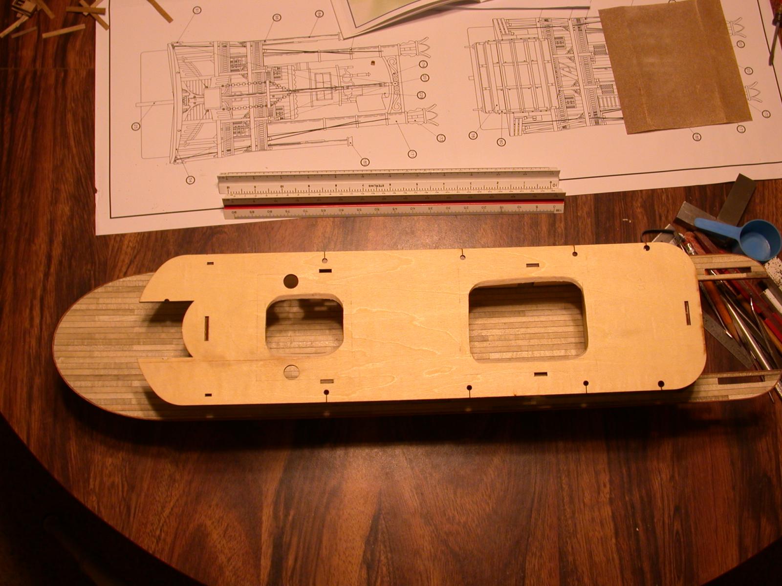
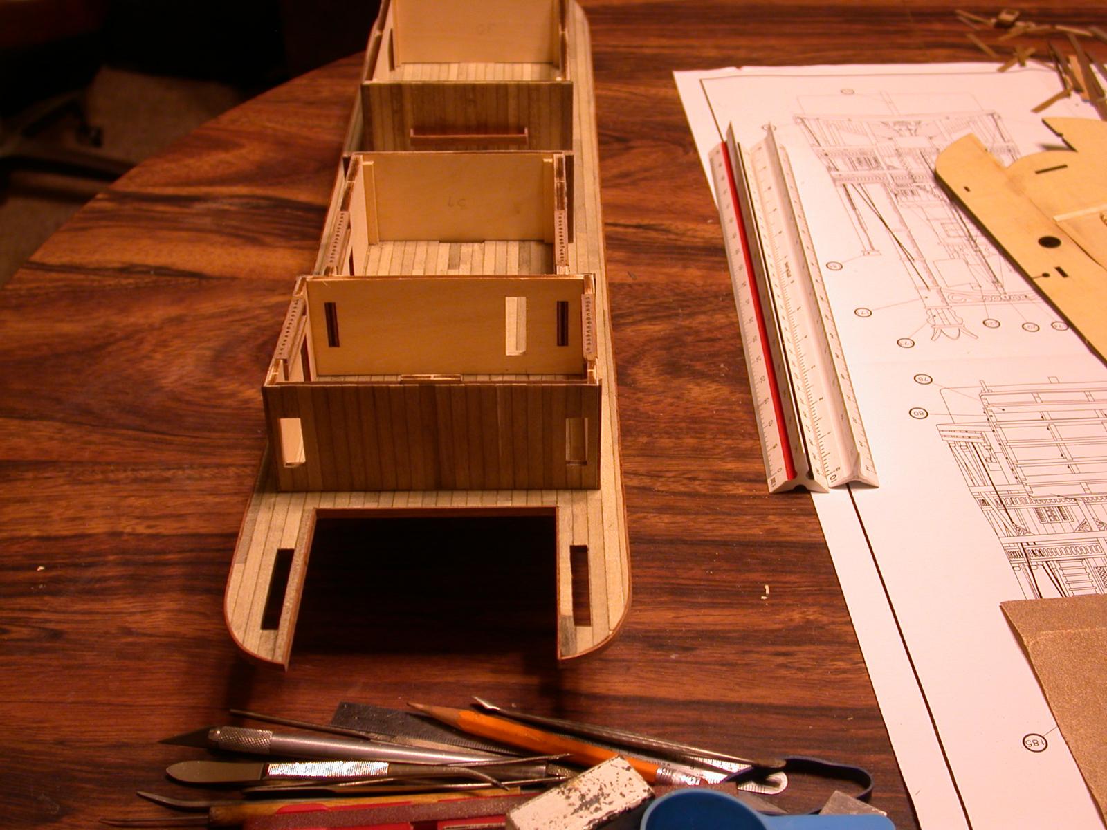
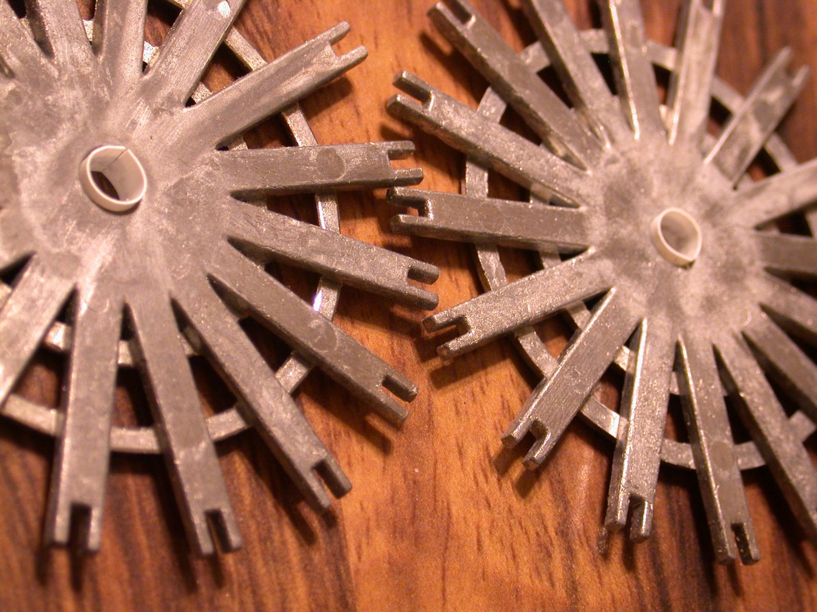
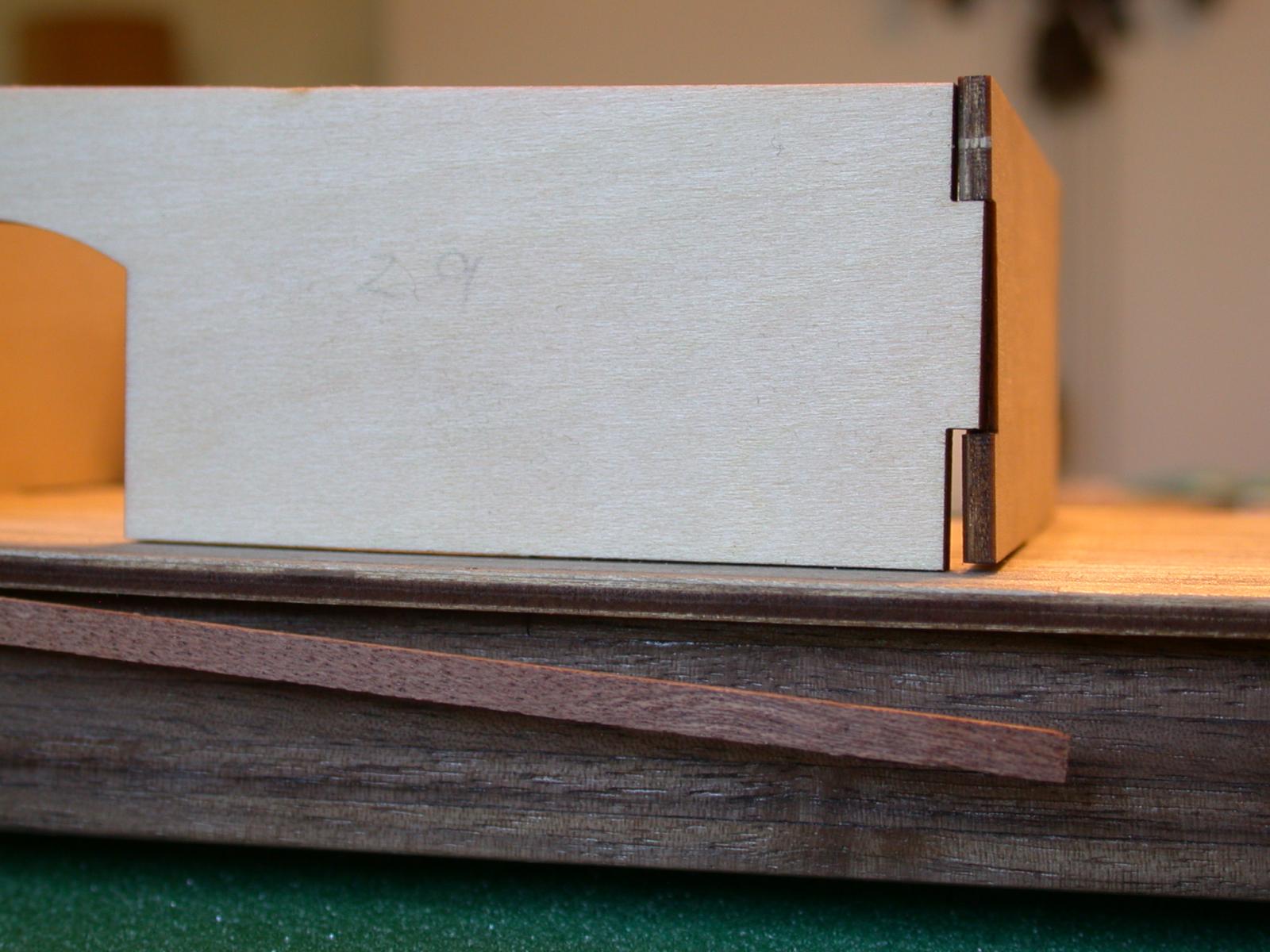
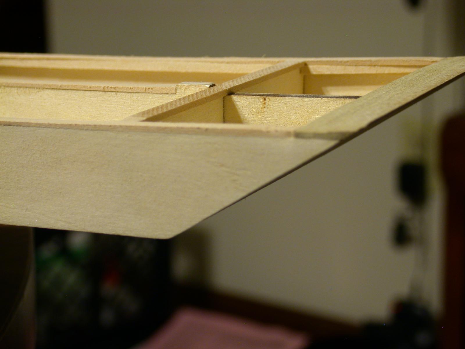
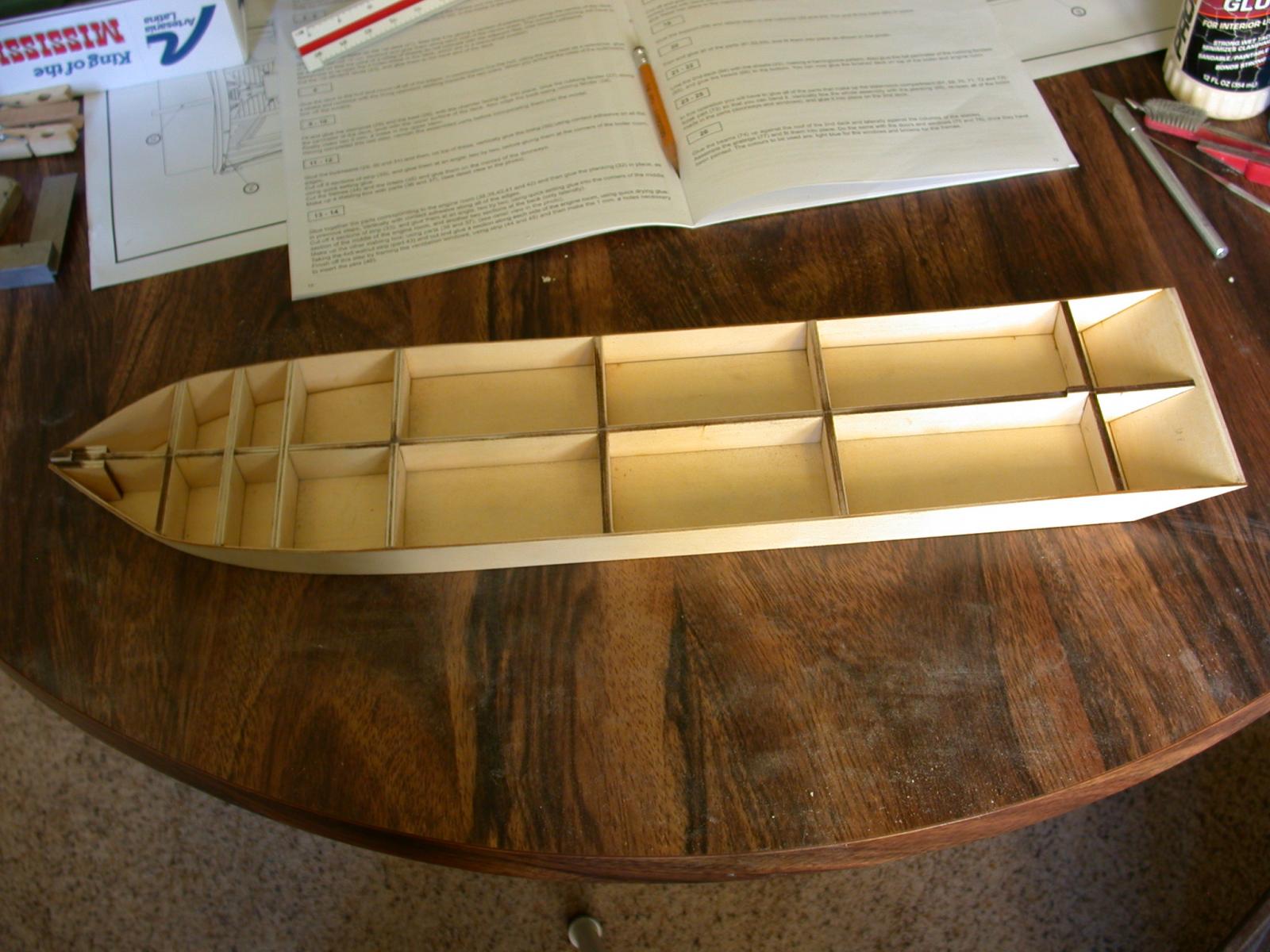
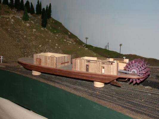
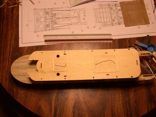
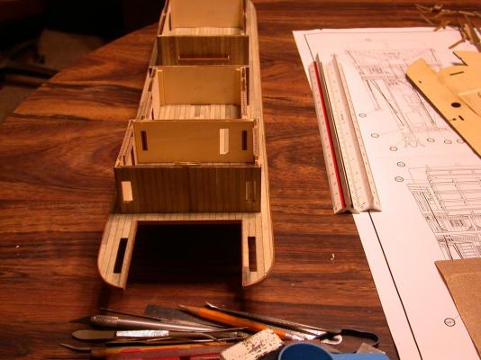
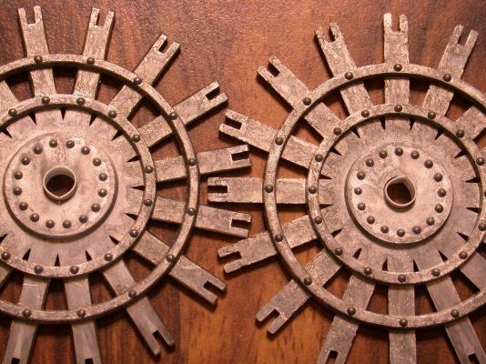
I've assembled and glued the boiler and engine rooms now that the slots have been corrected. I took some time and sanded the bottom of the walls so that they fit the curvature of the deck. This picture also shows the keel stands that I will eventually mount on a wooden plaque - both were purchased at the local craft store. The stands are actually wooden napkin rings. The second deck was dry fitted as seen on the previous post. I cut these access holes to be able to get into the engine and boiler rooms when the ship is finished. I planned to have the staterooms and top deck removable. This will leave only finger room, which I hope is enough. Some ship builders do it inside a bottle. I also plan to install lights and the access holes are a major leak between the decks. So I made up hatch covers from the cutout pieces. The original cuts were beveled - approximately 45 degrees to the center of the hatch. This was to allow the cutout piece to rest in the opening, but it did not work so well; the pieces occasionally fall in and are near impossible to get back out. Plus they still leaked light between the decks. The solution was to line the top edge of the hatch with planks to force everything flat and level. Chain and eyelets from the kit was to form a low profile handle to retrieve and replace the hatch. It seems to work well in tight places. The view from the rear of the boat shows a not so obvious cutout in the wall between the two engine rooms. It will be evident shortly how this is necessary for providing power to the paddlewheel. The last two photos attempts to show the difference of filling the edges off of the paddlewheel hub castings. the wheel on the left has been reworked. It is a lot of work and if I am the only one to notice it, so be it. Additionally, the styrene shims are visible where the new shaft will fit snuggly into the wheels. The kit provided wooden shaft did not fit the wheel castings, nor the crank and not even the block holding the paddlewheel to the deck. I don't what AL was thinking. More about this in the next post. Rick

-
Your ship is looking real good. I'll bet you will be getting a lot of first class passengers. Rick
-
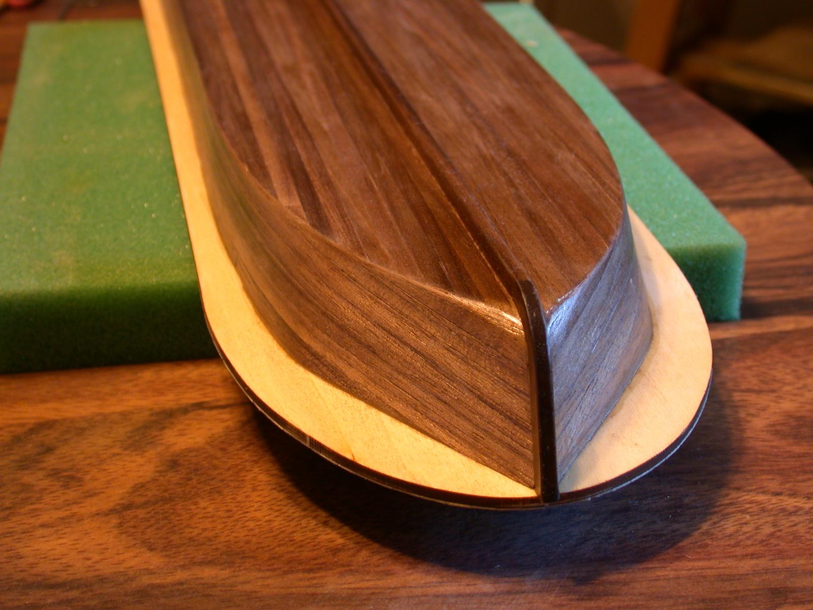
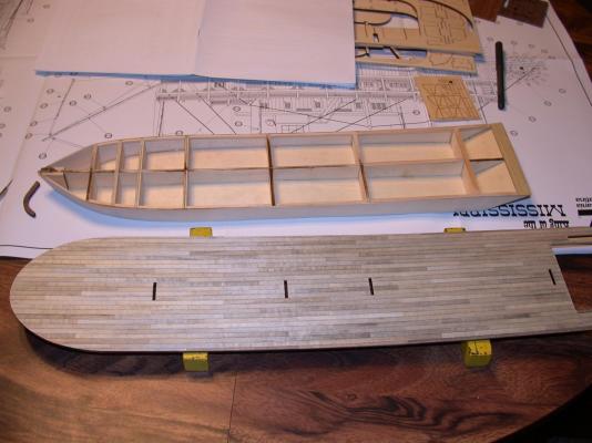
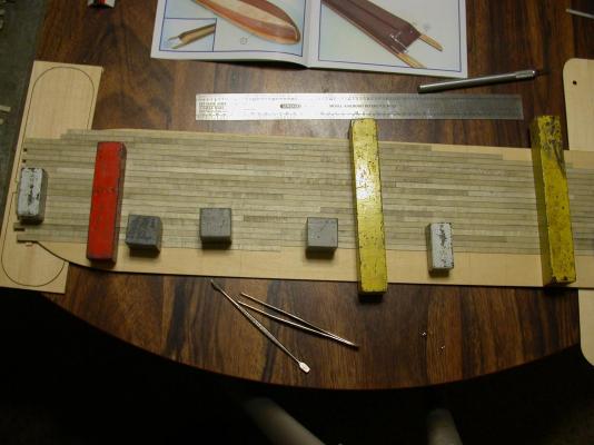
It has been awhile since I have added to this build log. I tried three times to update on Halloween night and thought it was internet gremlins eating my posts. They may still be out there. I am trying a different way of signing in and out of this site to see if this works Thanks Ollie for your interest in my build. I hope you continue to check in. Dragzz I appreciate the photo of your sternpost. It looks like a tight fit. The problem with my sternpost was it was too long where it meets the keel and too short where it meets the bottom of the first deck. I cut off the longer part of the sternpost and used the scrap to fill in the gap under the deck. It took some careful sanding and it worked by just taking my time. Laying down the hull strakes was an interesting application of weights and clamps. It came out better than I hoped. I now have an appreciation for those who plank on frames of ships with complex shaped hulls. I applied two coats of polyurethane and it looks beautiful. I hope the photos do it justice. With the first deck and the hull fully planked it seemed a good time to try a dry fit of all of the decks. It looked so cool I just had to include a photo. It was a good thing I did this test fit. I encounter the misplaced slot in the first deck that Adreike mentioned in his build log and was able to fixe that like, I think it was John suggested . Additionally I noticed a wall of the boiler room that would not settle right, so I widened that slot also. That's all for now.


-
This is a test. Four previous attempts failed to get posted. I do not know what is wrong.
-
Those stairs look great. It would be a real joy to walk up stairs like that.
-
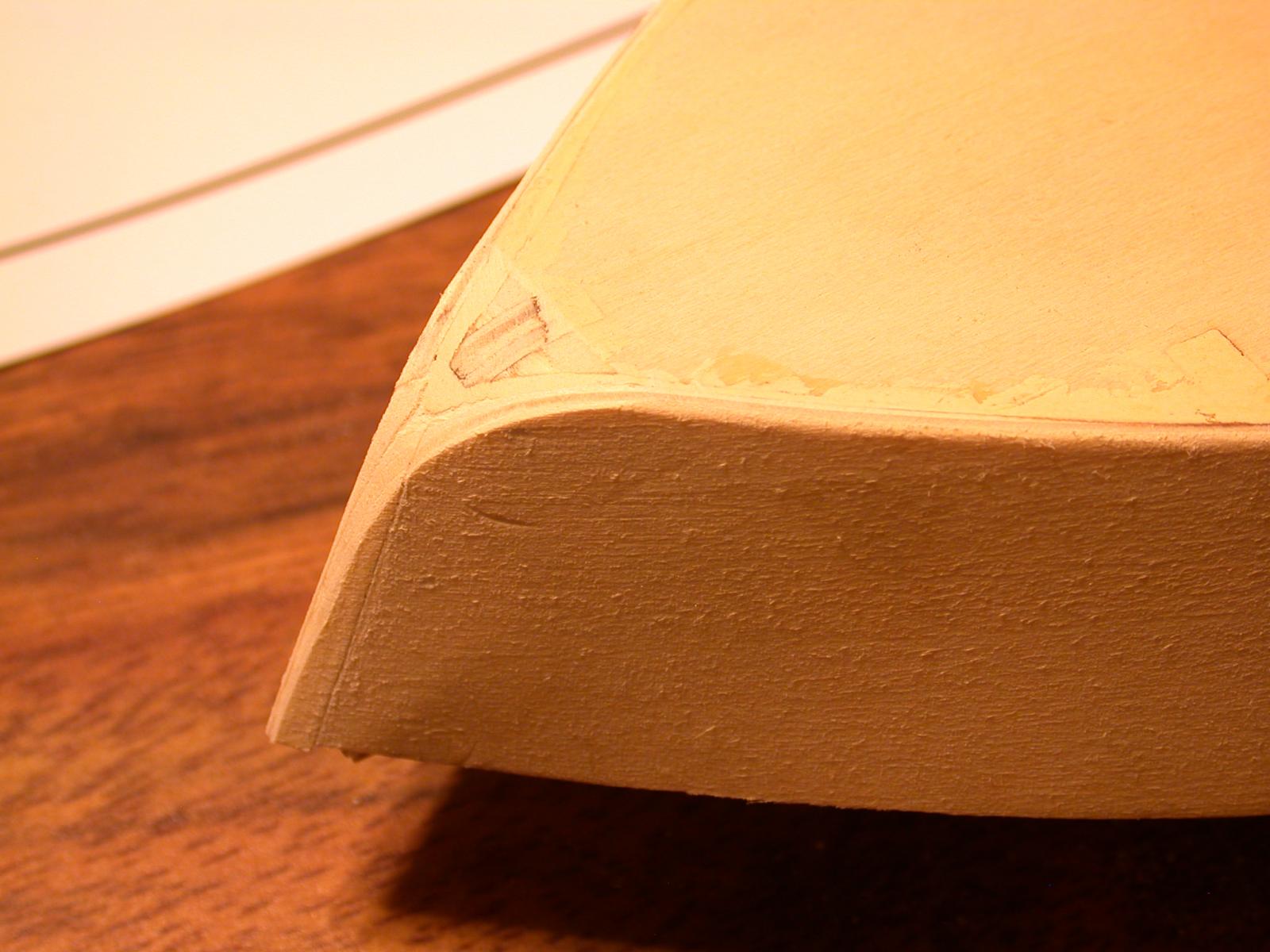
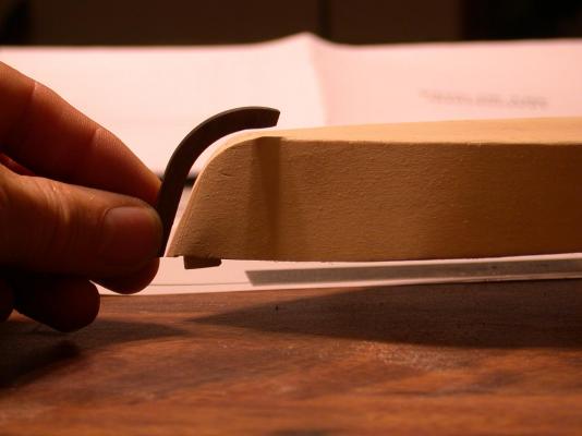
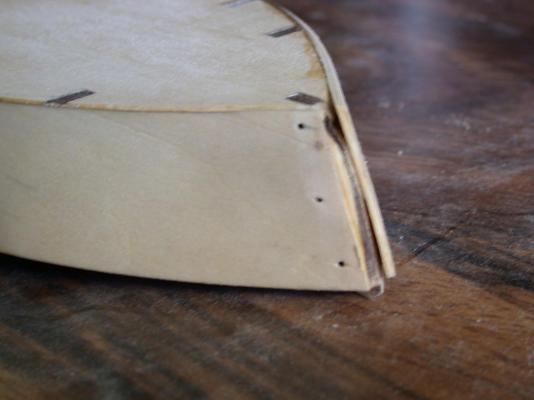
Progress is being made. I finished planking the first deck. I like how it looks being kind of rough. I imagine that older riverboats had weathered decks something like I got. I am currently working on sanding the bow after filling the small voids with wood filler. I am using Part 25 Sternpost (as AL calls it) as a pattern. By sanding straight across the bow (below waterline) I am making a simple curve that fits snuggly to the sternpost. This is supposed to allow the strakes on planking the hull to butt into the sternpost. But it nearly impossible for strakes on the bottom edge of the side bulkhead to make that last sharp bend to meet the sternpost. The next step then is sand the lower edge of the side bulkhead so the lower strakes can twist and curve smoothly and look like what a good bow should. (does that make sense?) Another problem with that %$#! sternpost is it doesn't seem long enough to reach the top of the bow. It is too short by about 5mm. Anybody have a solutions for this? Hope to have the hull planked before the next post. Rick
-
Dragzz, Your build is looking good. I have learned a lot by reading your build log. Your project is moving along fast which is good because you will stay ahead of me. My KoM build is better thanks to your comments. I will keep you posted. Rick
-
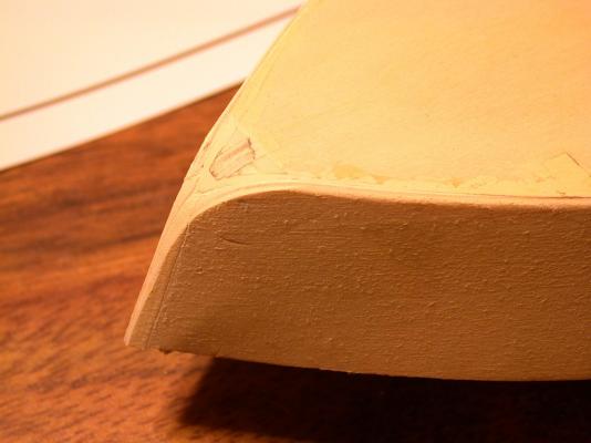
Dragzz, thanks for your reply and compliment. I did like you suggested and the bow looks so much better. It is nice and sharp like an ice breaker ship. I guess the next step is to sand it down to be more like the picture in the kit as well as like the bow of your build. And Don, thank you for looking in on my build and the nice comment. The next photos are of the stern of my hull. Most real steamboats have a big vertical bend both front and back. I think the bend of the AL hull needed a little more bend so I added about 3 mm at the very end of the stern. It looks like thicker bulkhead struts but they were all installed flush with the top of the original side bulkhead. I kept the curve under the deck as smooth as I could. I realize that all of the decks will be with a deeper bend, but that seems to be the way of steamboats. Look at pictures of the Natchez. And the last photo is a work in progress on planking the first deck. I like how it is coming out. I hope planking the hull is this easy. Rick
-
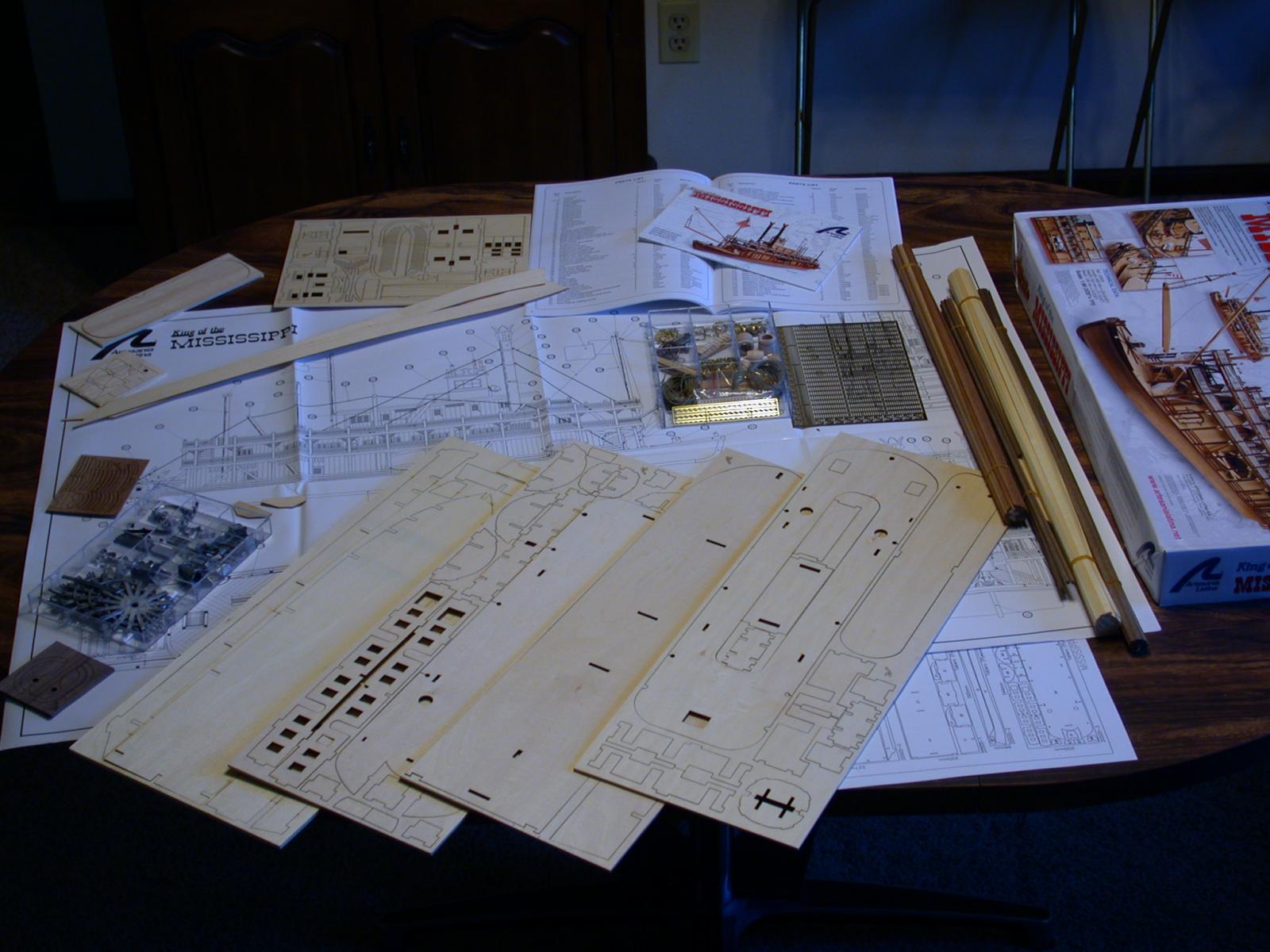
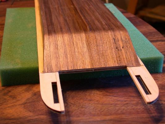
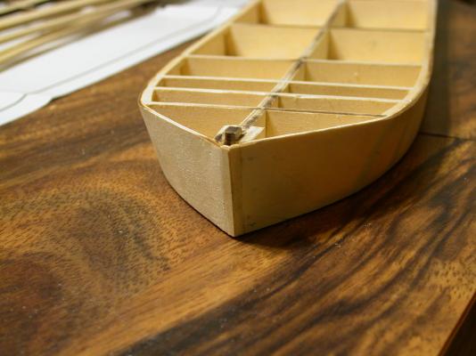
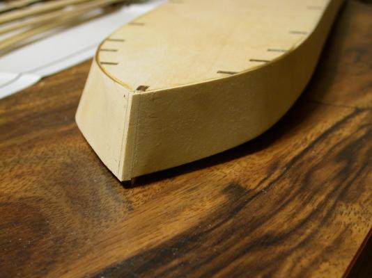
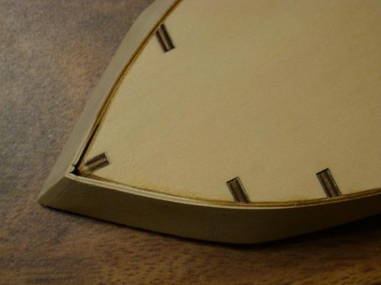
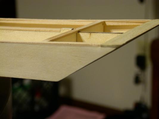
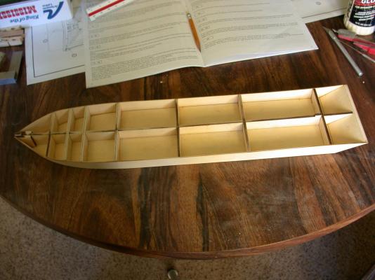
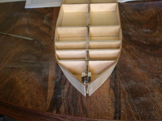
I have been so impressed with the modeling on MSW that I decided to join in on the experience of building a wooden ship. I really like steamboats and saw somewhere that the AL King of the Mississippi is one of the better kits but as I am finding out they all have their problems. My kit arrived a few days ago and I am already needing the advice found here on this site. I have enjoyed and learned a lot by reading the build logs. Before stating my current problem, let me state my ambitions for my KoM. I like the exquisite models with varnish and polished brass but I want to try make it look like it has been "down the river" a few times. I love the interior lights so I am going to try that. Being familiar with 1:87 in model railroading (HO scale) I am going to shift many of the modeling details about 10% and use what is available from local model train hobby shops. And lastly, with great apprehension, I am going to motorize the paddlewheel. Starting with photos the full contents of the kit, followed by a couple of shots of the hull, a close look at the bow. The two side bulkheads don't want to meet a the point of the bow. More sanding seems to distort the bulkheads. What am I doing wrong here? What do I need to do before I start the hull planking? I can knock it apart if I have to but I would rather not if there is another way to do this. Any help will be appreciated, Rick

- 44 replies
-
- 1
-
-
- king of the mississippi
- artesania latina
- (and 2 more)