HOLIDAY DONATION DRIVE - SUPPORT MSW - DO YOUR PART TO KEEP THIS GREAT FORUM GOING! (Only 20 donations so far - C'mon guys!)
×

Aa-schipper
-
Posts
61 -
Joined
-
Last visited
Content Type
Profiles
Forums
Gallery
Events
Everything posted by Aa-schipper
-
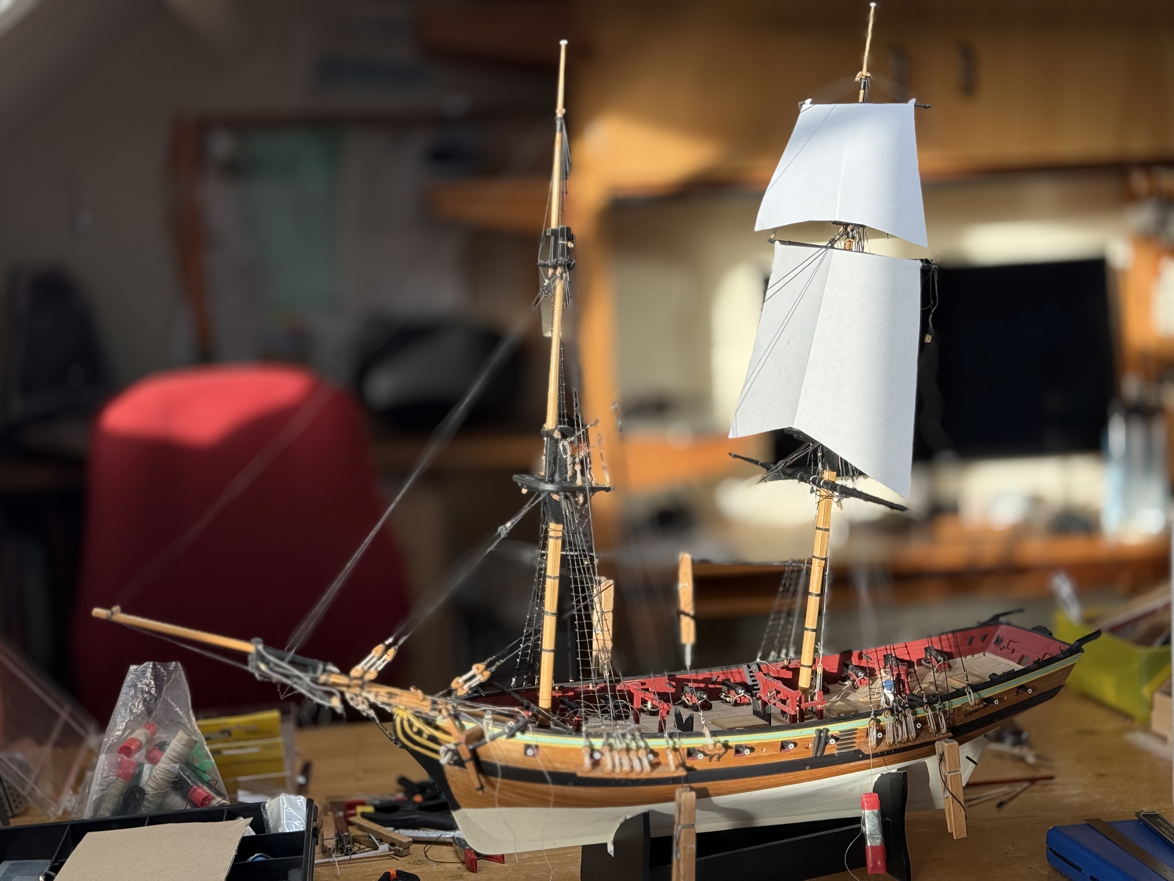
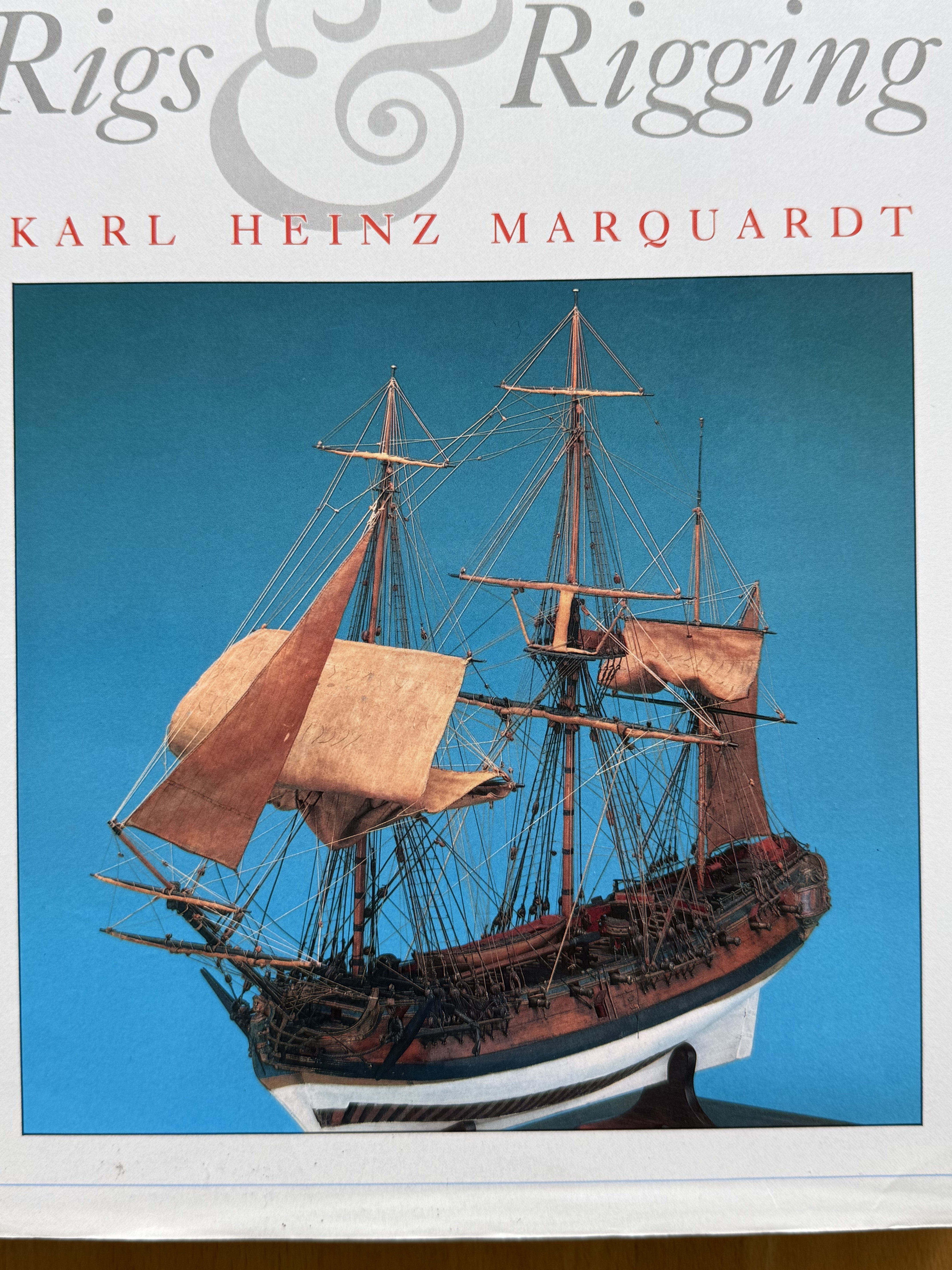
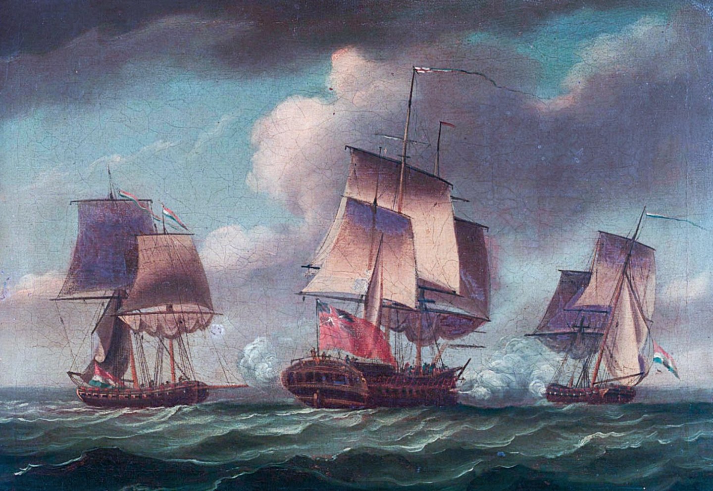
 In between other hobbies, the Mars is progressing bit by bit. The main step now is that I’ve attached the crossjack to the main mast—ropes and knots only, no tricks with pins, because later I may want to set the sails not quite squarely. I am now trying to determine the size of paper templates for the sails, by hanging the other spars on the main mast in place temporarily by a single thread, and stick the simple paper sails to the spars. I want to keep the spars detachable for the moment, so as to be able to tie the(still to be made) ‘silkspan’ sails to the spars separately, with some working space around them, before attaching the whole set to the mast permanently. The idea for the final result is to have some sails set, a few drawn up hastily, and the topgallants furled up more neatly, more or less as shown in Dodd’s (undoubtedly fantasised) painting of the Hercules and Mars in action against HMS Artois (detail from the painting on the website of the RMG, where the Dutch ships don’t have t’gallants), or on the cover of Marquardt’s Eighteenth Century Rig.


-
Enthused by Frolick’s recommendation, I searched for book reviews before committing forty-odd euros (plus shipping costs), and decided to let this one pass: it was recommended in the journal Sea History for its social history aspect and for publishing some unique illustrations, but was said to be faulty when it came to technical aspects—which would be my main interest (https://issuu.com/seahistory/docs/sh_087_winter-1998-99/45).
-
Revisiting this old question for my planned next build: agreeing that likely all (full-rigged) ships of the Royal Navy were long since copper-bottomed by the time of the Napoleonic wars, does this also apply to smaller vessels, such as cutters or schooners? And what about such smaller vessels in private use, both purpose-built privateers and merchant fleet? Your opinions would be welcome!
-
Hello Nipper, Probably you're correct about most of the sheets: the book, and of course your Caldercraft kit, will give you enough information to build the ship. However, maybe the deck layout may be a part of the kit you want to change from the kit to get closer to Irene. Therefore, I attach scans of the two drawing sheets (in halves, because of their awkward lengthy formats) that show the wheel, hatches, pumps, capstan etc. Might come in handy for you or others. (And gives you a chance to learn some nautical terms in Dutch 😉.) Irene deck lay out Petrejus.pdf
-
For figurines, I used several sources: - Some old-fashioned metal models from Amati; - From Vanguard Models (@chris watton) I obtained figurines of captain Lord Cochrane (as a stand-in for 'my' captain Pieter Hoogeboom) and of a crew loading a gun; - In different 3D-print file sources on the net I searched for '18th century mariner', 'pirates' and similar terms and browsed through many pages with images of the available .STL files; I bought a couple that looked convincing and had them printed on a resin 3D printer by a kind acquaintance. They're ready to be glued in place once I'm done with belaying the rigging on deck.
-
Hello @Nipper, Thanks for your renewed welcome. You mentioned Petrejus' book on Irene. I just received a second copy of the Dutch version of the book, which I bought online because I realised that my first copy missed all but one of the build plans on loose sheets. And now I wonder how many drawings there were in total, because mine are numbered, but not consecutively. However, since the highest number is 111, I doubt if there really were more than a hundred separate sheets? Maybe you can compare with your copy to see whether you or I miss some: Evidently, the 'Extra' photo copies and the black-and-white photo do not belong to the original book.

-
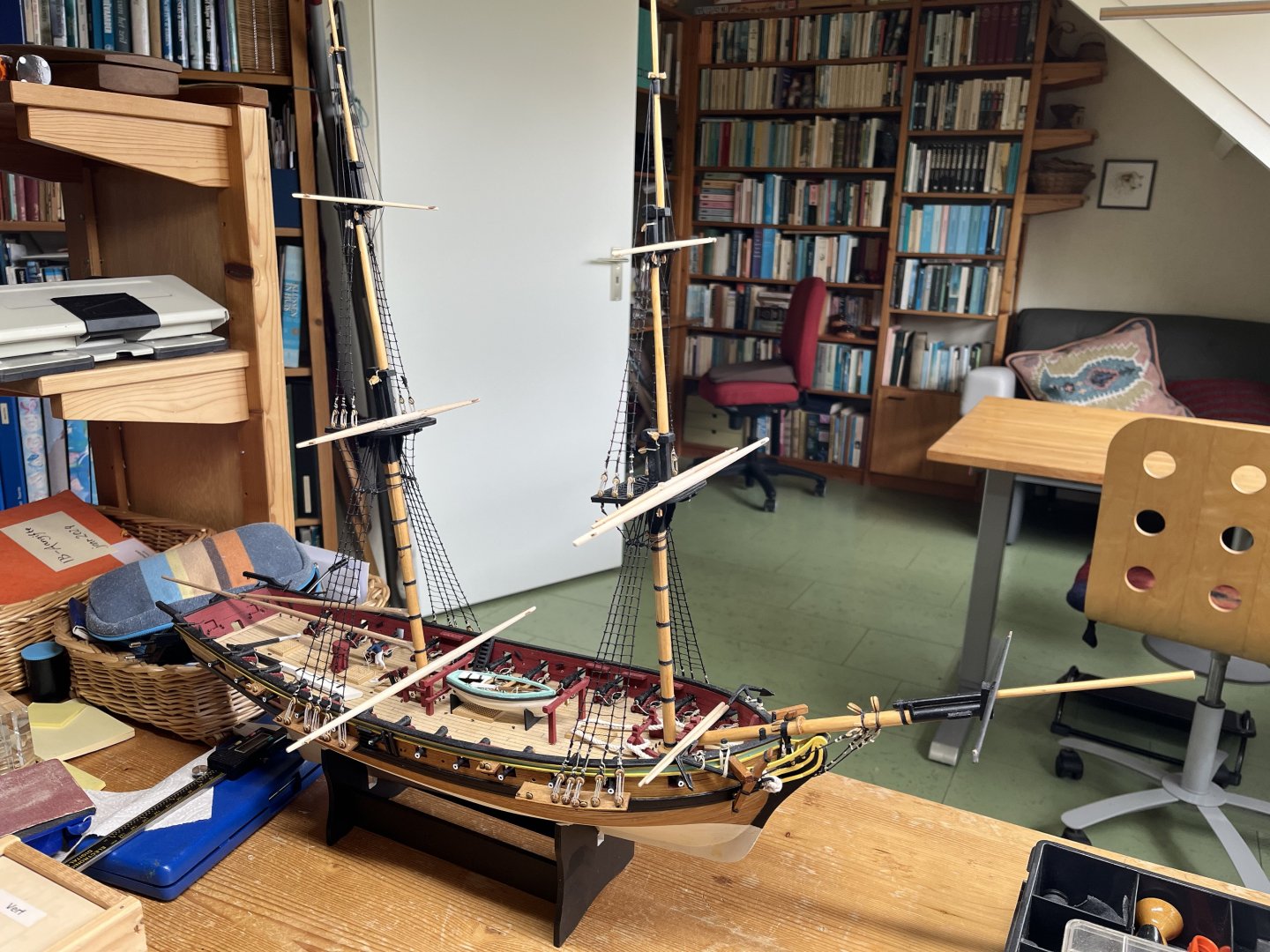
Alive and swimming I started following Gaffrig’s build log in which he apologised when he came back after a year of inactivity on MSW (link). Returning after a year and a half, I can't think of what I then have to say, short of kowtowing in public. Moreover, a week ago I had to commemorate (not celebrate!) the fact that I have had this kit for ten years already. Over the years I have come to know more than probably anyone else about the Mars, its crew and its owner, but the ship still is not finished. Anyway, I have some progress to report: - Following Julier's suggestion in his New Period Ship Handbook (and my own instinct) I glued the masts in place before mounting the spars on them. The idea is to have more working space to attach the rigging - I have installed the shrouds, fiddling a bit with the height of the deadeyes, because the simple jig suggested in the drawings of the building instructions did not work for me and the more sophisticated solutions to keep a couple of deadeyes on exactly the same height shown in some build logs (which I forgot to retain for linking here...) I discovered too late. Well, I assume that Dutch privateers did not work to the standards of Royal Navy officers, so maybe my sloppiness reflects reality somewhat. - Tying in the ratlines as detailed in the HMS Mars building sheet I found easy and even enjoyable. (Maybe building a three-mast ship model is not such a drag, after all!). - Most recently, I have planed and sanded the spars to shape from the round dowel in the kit. Somehow, I did not find the 4 mm piece needed for the driver boom and gaff, which goes to show you should check the box content thoroughly upon arrival--or to build faster so you don't lose things over the years. At a nearby hobby and art store I could stock up on dowel, so that problem was solved without much trouble or cost, though it's beech wood instead of lime tree(?) as in the kit. Since the spars will be painted black, no-one will notice. - In the meantime, I have studied some issues of historical shipbuilding and rigging, and found out about some more differences between British and Dutch shipwright insights and traditions. The upshot is that I will continue to try to adapt the kit to what the Mars may have looked like when she started her cruise against British shipping in November 1781, but without spending too much effort or money on buying or fabricating historically (more) correct pieces. For instance, Petrejus in his Brig Irene showed that the tops in Dutch ships had an almost semi-circular form as opposed to the squarish tops of British ships, but I am not going to remove the tops that I already glued in to the masts. However, I did strike the dolphin striker from the bowsprit as it was a British innovation popularised after Mars was built, and will adapt the run of lines accordingly. For another example, British rigging used open hearts in some lines, whereas Dutch riggers worked with double blocks. As a (more or less) novice model builder, and as the British version are available in the kit, I will keep the open hearts and other blocks from the kit. The result of this all will undoubtedly be a hotchpotch of British, Dutch and maybe even French characteristics, because my main source besides Petrejus is Eighteenth-century rigs & rigging by K.H. Marquart, who gives impressively detailed and extensive descriptions of British, French, German and Dutch rigging. But when he writes about "continental" ships, I am not always sure if that covers French and/or German and/or Dutch. Never mind; I'm not expecting maritime museums to make a beeline to buy my model once it's complete... As long as it satisfies myself, it's ok. - Talking about satisfying myself, I have decided to make a bit of a diorama of the model by putting a number of figurines on board (though by far fewer than the 146 heads that must have manned the Mars originally). Another way to make it more lively that I want to employ is adding sails to the model. The idea is that I want to show a privateer in action, with: (1) a crew charging one of the fans, (2) a number of hands ready to board an enemy ship (an alternative outcome of the battle with HMS Artois), (3) some musketeers firing from the main top. This will require sails set for a moment just before boarding: advancing at a slow pace (with most sails furled hastily) and the wind coming more or less from abeam so that some fore-and-aft sails can be shown. - I have decided to use silkspan for sails, as I think it will give a better scale impression than textile. The material has been ordered and I watched some YouTube tutorials, which I may linkt later once I'm coming to that stage of the build.
-
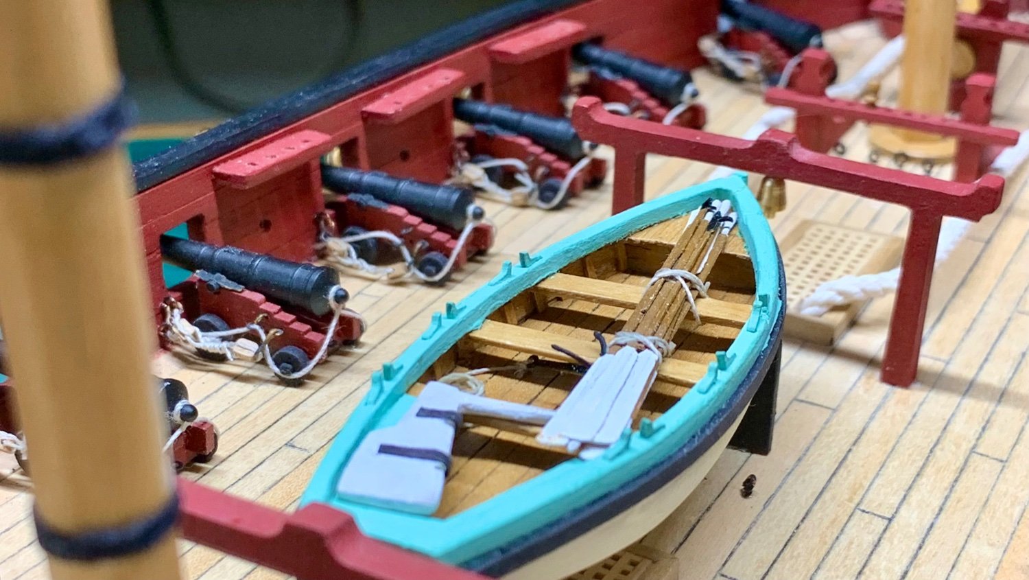
The deck is taking shape: the guns have their breeching and outhaul tackles. The outhaul tackle is an extra. Having seen the display of guns on HMS Victory, HMS Warrior and HMS Unicorn, it appeared that they must be shown, and it makes sense, because without outhaul tackle, you cannot stow the guns next to gunports and they take no precious space on deck, the ends being wound up between the blocks on either end. Hence I bought the smallest blocks I could find online (2 mm), measured out some 7 meter of .25 mm rope, and put in a bit of time. I had previously provided the gunports with four eyelets: two for the breeching rope and two for the outhaul tackle. In the picture, also the additional cutter is shown. According to Petrejus (and as one may read in any Aubrey/Maturin novel), ships had a number of cutters, gigs and the like, so two (the other one will hang in the davits a the stern, eventually) seemed to me the minimum for this privateer. To be honest, I'm fairly satisfied with the look of the deck like this.

-
I'm afraid you're right, @amateur! So slow, and still I'm too hasty and did not check the building plans sufficiently. Now I'll take another month to think of a solution.. 😉
-
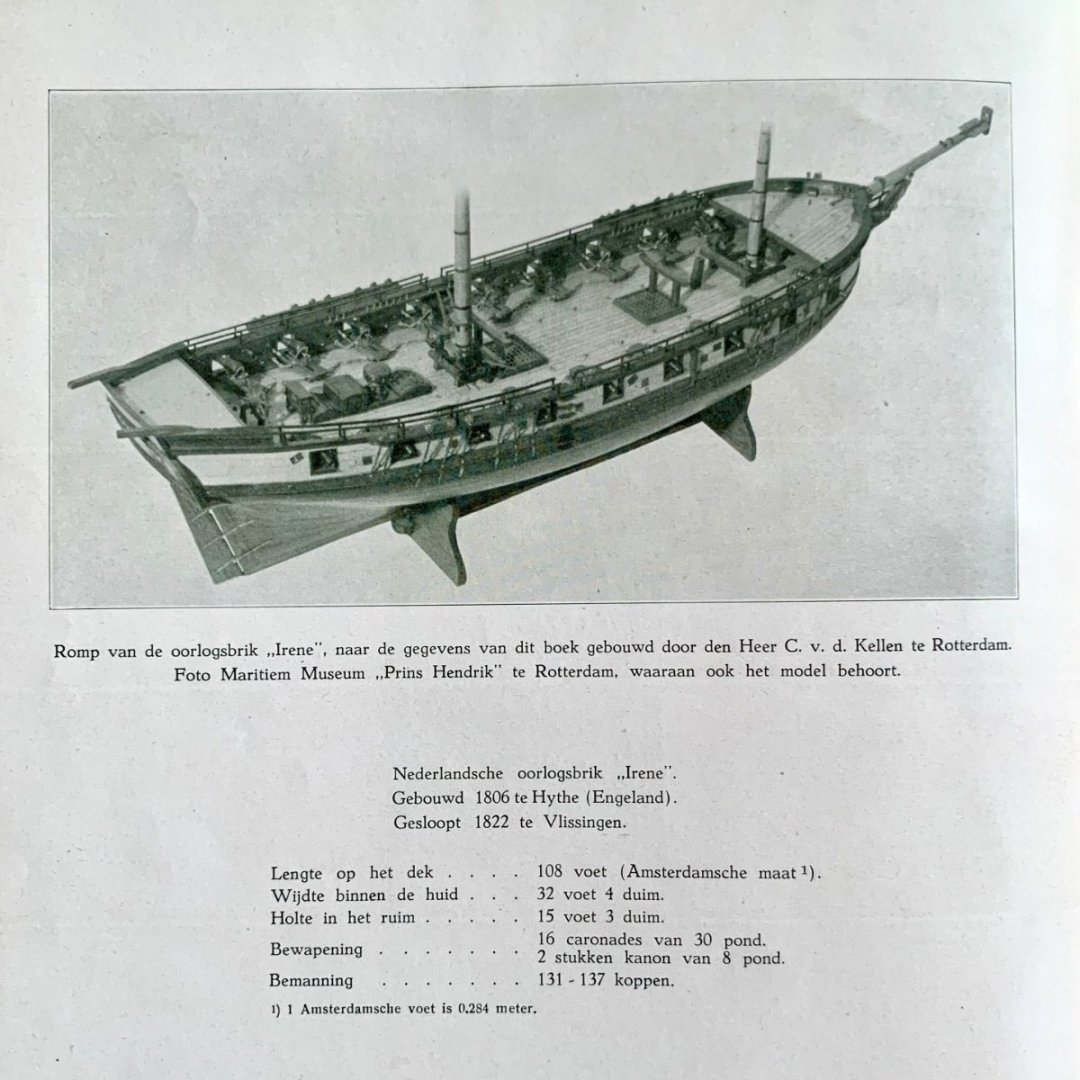
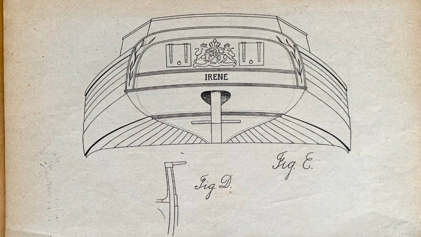
Well, Hardly necessary to respond to you anymore, @Nipper, as the main answers are already there: Irene started life as a Cruizer-class RN brig, but Commander Fanshawe struck to the Dutch fleet after foundering on the Dutch coast due to a heavy storm in December 1811. Let me add pictures of the frontispiece of Petrejus' book, which gives the sizes (in amsterdam feet = 0.284 m = 0.932 ft) and a detail of one of the plans in the book that shows the design of the stern.
-
Hello Nipper, Thanks for your kind remarks. Please give me a day to check that out. The book (long out of print) has some drawings and measurements that should be helpful for you. But I’m off for the rest of this day…
-
I wonder if anyone still follows my build log—I’m soooo slow. After enjoying summer, vacation, sports and other hobbies, which took me well into the new year, I finally have a little progress to report on Mars. The masts were filed and sanded into more or less correct shape—not down to the historically correct sizes at the level of a tenth of a millimetre, I admit, but no-one of my expected audience (very few family members, all bigger landlubbers than me) will notice and I find it downright scary to make the wood so thin and fragile. With my clumsy, erratic moves the risk of breaking something during the build is big enough as it is. But what makes it worthwhile to post about the masts, is that I found in the priceless Petrejus (confirmed by other online sources) that Dutch mastcaps followed the French design, with a closed ‘head’ on the cap rather than the simple oblong block with two holes in English style that are part of the kit. Starting from the provided English-style pieces, I simulated the Dutch/French style mastcaps with a couple of scrap pieces of 2 mm walnut. (Photo from before painting them black, for clarity). Also in Dutch rather than English style, and also found in Petrejus’ book on Brig Irene, I made two holes just above the fid for raising and lowering the topmasts by cables that were hung through the mastcaps when topmasts had to be taken down, e.g., in stormy conditions. In English style, that part of the topmast would have been octagonal with holes for cables in diagonal lay out, which Petrejus claims was more efficient as it avoided the cables getting entangled—but apparently Dutch shipwrights did not do such newfangled things.

-
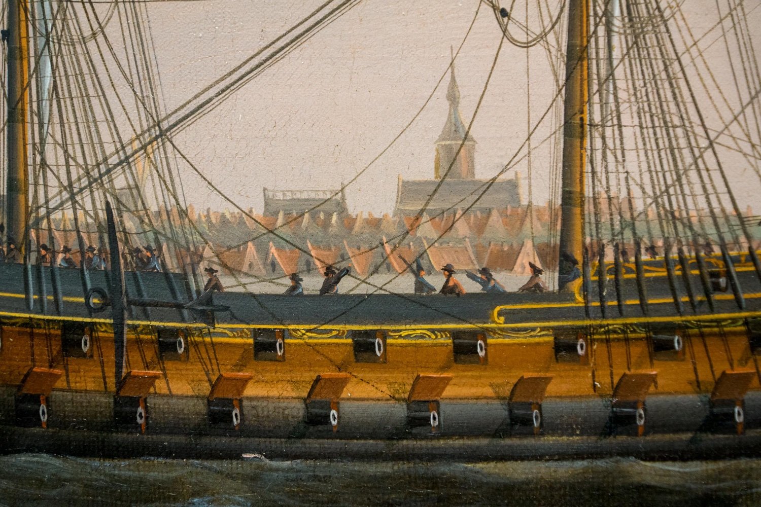
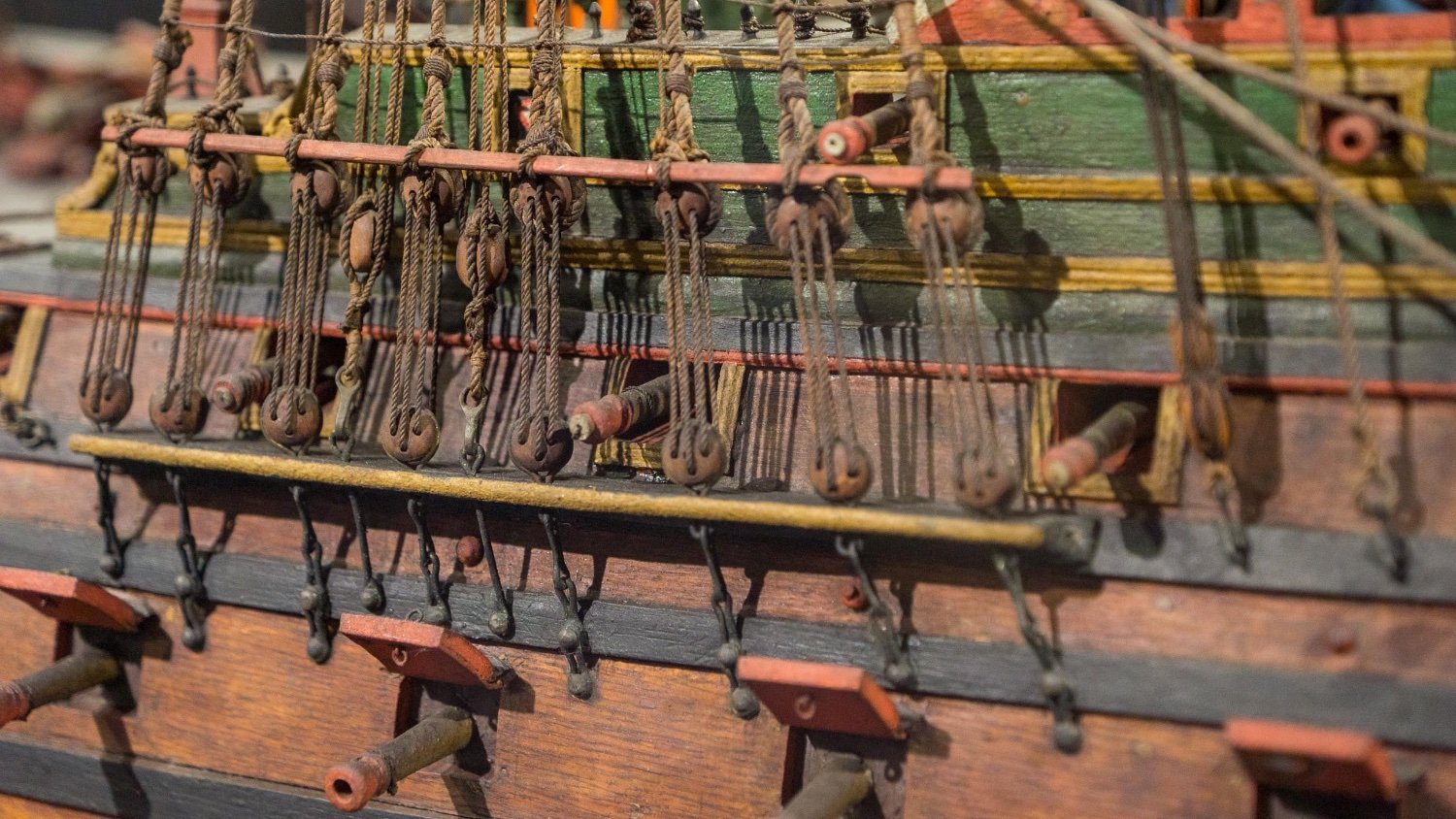
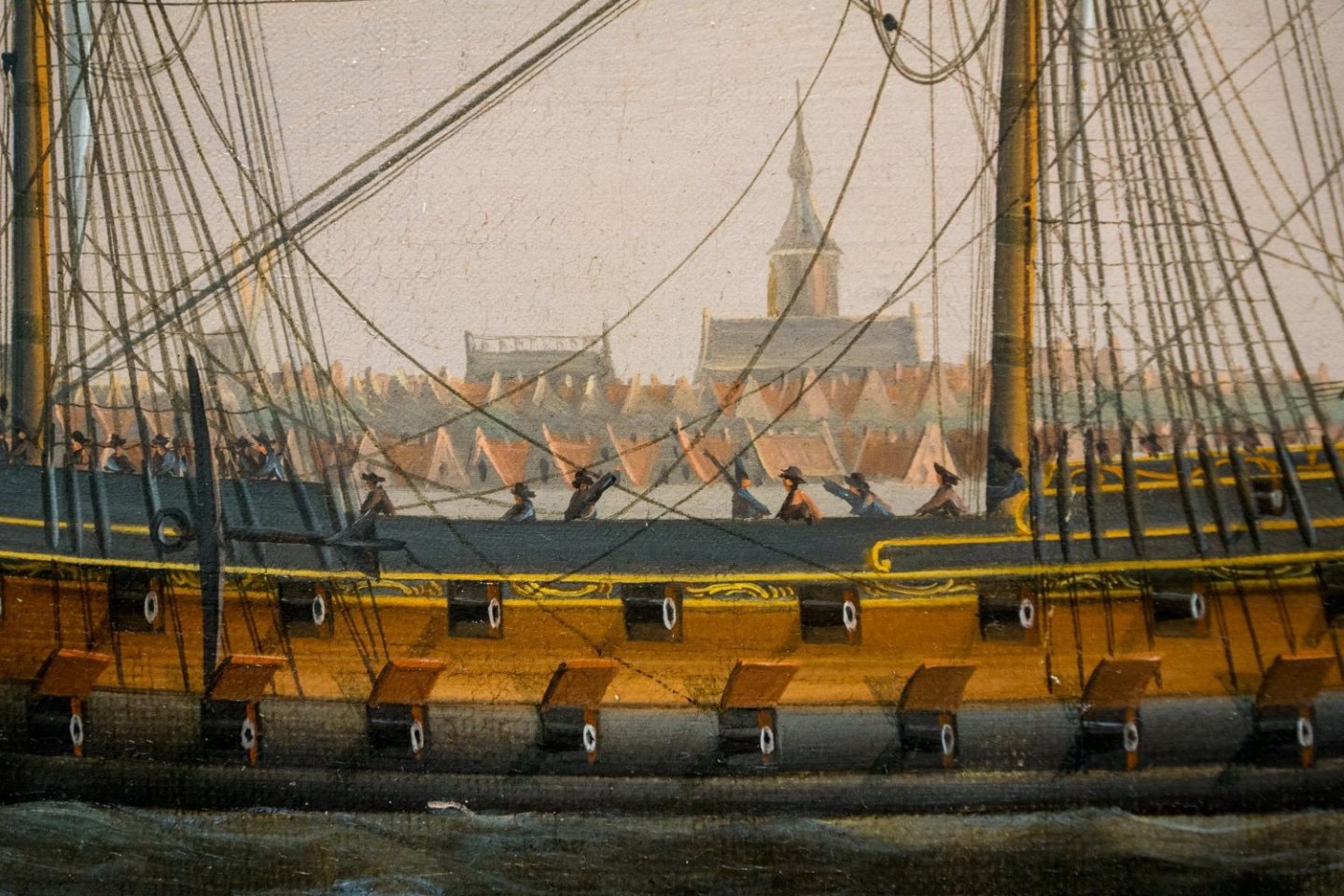
Maybe a matter of 'fashion' that might change over time? I found a couple of paintings from the 1780s-1800s where ship guns were given a white circle around the mouth. The ships depicted were Dutch, though the painters were both Dutch and English. And in the Rotterdam Maritime Museum there is a contemporary model of a 1720s ship with red 'socks' covering the mouth and part of the barrel. Sorry, we're going a bit off-topic. To return to centring guns: both photos attached show guns neatly centred in the gunports both horizontally and vertically. (Info on pictures: my photo with detail of a painting is from Engel Hoogerheyden's painting 'Dutch blockading fleet...in the roads of Flushing' (1784) at the National Maritime Museum Amsterdam; my photo of a detail of VOC ship Padmos/Blydorp (1722-23) at the Maritime Museum Rotterdam; reproduction of R. Dodd 'Artois capturing two Dutch privateers, 3 December 1781' from the NMM Greenwich collection.)

-
Extreme lines, not your ‘thirteen in a dozen’ ship. What a sleek hull, and that extremely long bowsprit 😍! Very beautiful and certainly on my wish list, too! Thanks, James, for this sneak preview into the building manual 😉
- 80 replies
-
- 6
-

-
- Grecian
- Vanguard Models
- (and 3 more)
-
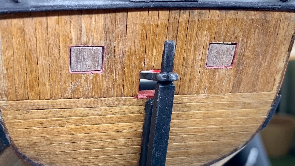
Stern chaser gunports closed While I'm collecting courage to attack the deadeyes 😉, I have followed another of Petrejus's suggestions: the stern chaser gunport were closed unless in use, he contends, so I made two little hatches from some centimeters of leftover walnut, glued onto some leftover boxwood (never throw away scraps of wood of any size!). I'd love to make them working, with real hinges. Had I thought of this in time, then I could have ordered some hinges when last I bought things from a modelling webshop (there is no specialised shop in my neighbourhood).
-
Sjors, I'll be curious to see how your Duyfken comes on. I've been aware of Kolderstok since a number of years, but want to finish my Mars before deciding if I go from 1:64 to 1:50. Could you please comment on the quality of the materials, e.g. how snug is the fit of bulkheads on the keel? Are there any helpful structures for making a rabbet (as Vanguard models now have), etc.? Judging from your pictures, it's looking good!
-
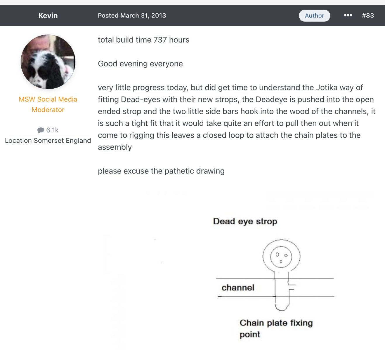
Deadeyes I’ve been wondering for a couple of weeks now how to make the deadeyes: what is Caldercraft’s intention with the two little protrusions on the bent metal rings that go around the deadeyes and then down through the channels? A search of this forum on the terms ‘deadeyes’ and ‘Caldercraft’ did not turn up exactly what I wanted, so I started to browse build logs of Caldercraft/Jotika models and just now I found @Kevin solved my riddle ten years ago when he built HMS Victory. So the point of the points is to squeeze them into the little slots in the chainplates and then let friction do its work. And a little CA glue to make sure, perhaps? I wonder how much force the shrouds will come to exert on the deadeyes and don’t want to get nasty surprises when doing the rigging. A thought on glues As regards CA glue, I’ve been (and remain) a believer in PVA for anything wood, as I found the superglue stuff way too messy and too fluid. To stick metal and wood together, I have used a glue I had for my archery sport, Bohning Flex-tite Platinum (https://shop.bohning.com/adhesives-arrow-prep/fletch-tite-platinum-glue/), a slow-setting glue (not too slow though, setting time 5 minutes) to stick vanes to arrows. Recently I bought Zap Yellow CA glue, the gel type, and that works even better, as it can be used in very small dabs precisely in the place where you want it while it sets much faster than the vane glue yet leaves you some time to adjust pieces. A thought on languages By the way, I much prefer the Dutch word for deadeyes: jufferblokken, which literally means lady’s blocks. Much friendlier idea to have rows of ladies smiling at you than to be staring at dead eyes 😉

-
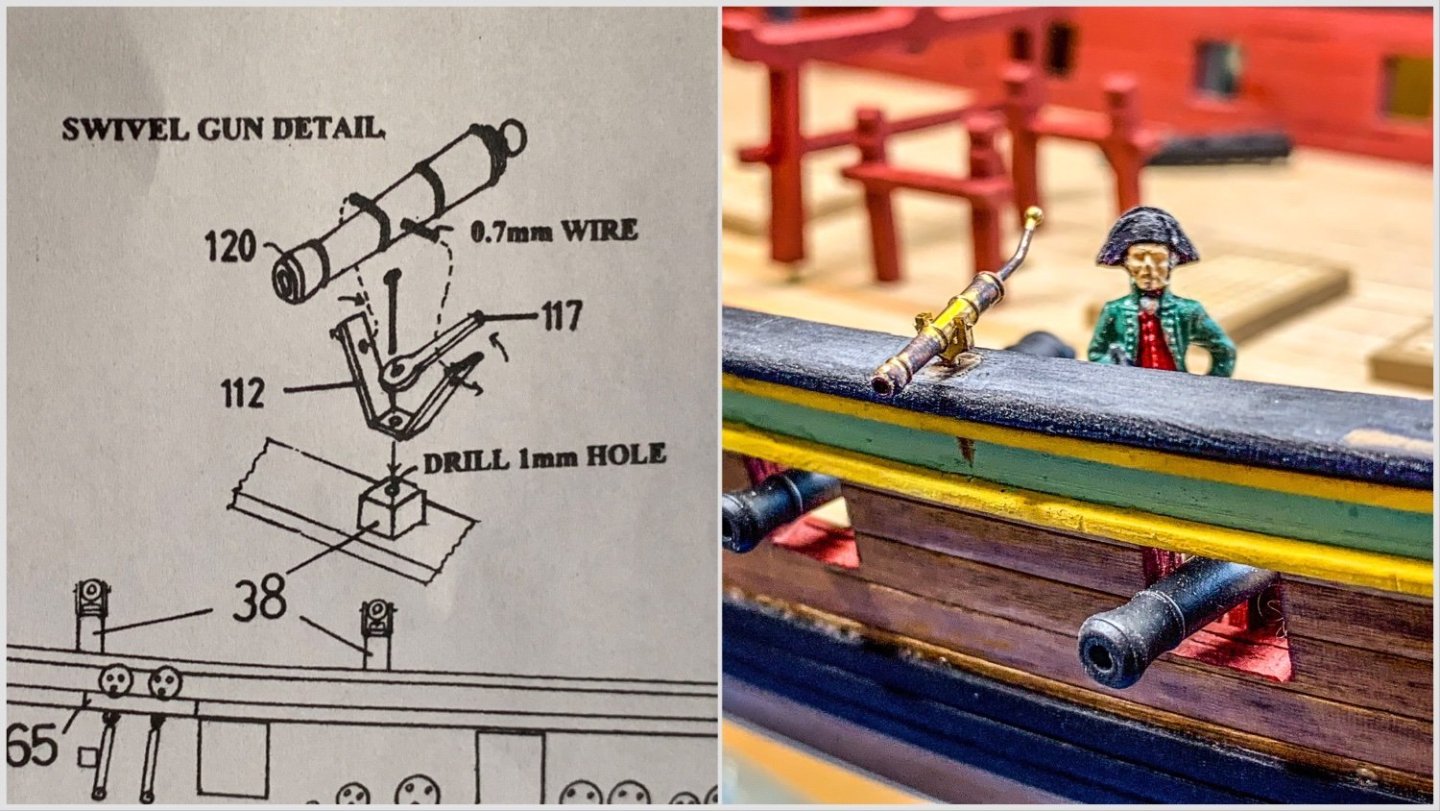
Swivel guns Imagining how life onboard might have been, back in 1781, is one of the things that gets me into a good mood—and it makes me glad I don’t have to undergo those hardships! A few little figurines help the imagination, and they also help to get a better understanding of the size of things. Which led me to some little tweaks of the kit at the swivel guns. First, putting the Amati figurine (I imagine it represents Head Surgeon Guiljelmus de Messemaker) on the quarterdeck, shows that the bulwark is as high as a man. The construction of the Caldercraft swivel guns, on a sort of pedestal and a swivel construction that gives even more height (see left-hand picture), strikes me as way too high to be practicable. Second, I found the guns in the box too bulky to represent light swivel guns. For those two reasons, I ordered a set of smaller-looking swivel guns (made by Amati again, as I noticed upon receipt) and I’ll put them directly onto the caprail, as I have seen it done on the full-size replica of VOC ship Amsterdam, lying behind the Maritime Museum in Amsterdam. Moreover, the bulwark of that ship is no more than hip high, if I remember well. (I’ve got a photo of it somewhere and can insert it into this blog if you, my readers, would like that.) Guiljelmus de Messemaker Why do I call the figurine Guiljelmus de Messemaker? Well, any reader of the Aubrey-Maturin novels knows that a ship isn’t a story without a surgeon, and on the Mars, the ‘head doctor’ was called Guiljelmus de Messemaker. So I wanted a figure in civilian clothes onboard—she was a privateer, after all—for which from contemporary paintings a green coat and brown breeches (and a red waistcoat—why not?) seemed appropriate, and I thought it might well represent the doctor. Perhaps surprisingly for such a small brig, there was also a ‘second doctor’ onboard, Samuel Zwetz. Their names are known, because they acted as witnesses in the published ‘Account’ of Mars’s ill-fated voyage of December 1781.
-
Thanks for the suggestions, @AJohnson and @BenD! Most of them I had been applying already, except the CA glue trick to harden the surface. So it’ll have to be the wood filler, drill again (with my pin vice drill—I don’t even own an electric one for model building), and repaint. Oh well, plenty other things to be done in the meantime, like the other deck fittings and anchors, to get into a good mood again.
-
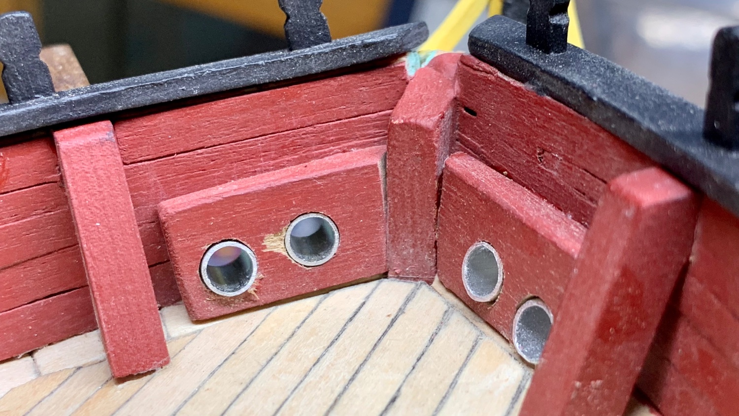
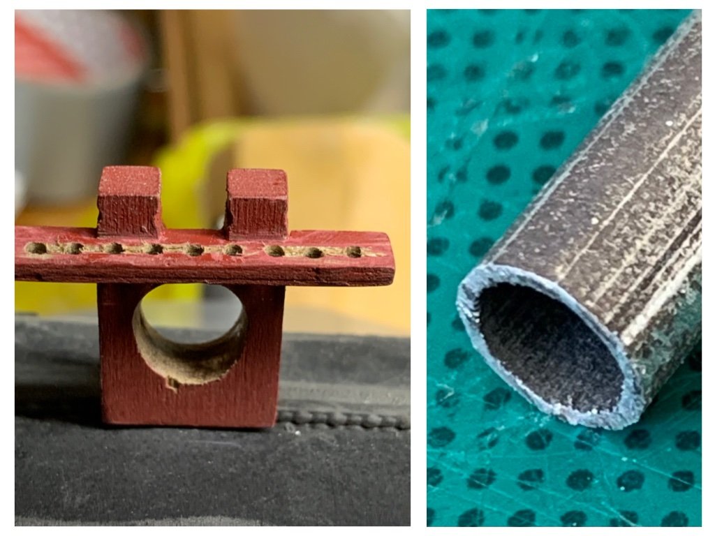
A bit of frustration at the end of the week. Expected but a bit of a disappointment is, first, that indeed the blackening solution based on sulphuric acid is not very successful for the metal casings in the hawse holes: it blackens the tube alright, but that's hardly visible on the cutting edge (right-hand photo). Paint was the alternative I had already thought of. Second, all belaying racks have beautiful holes straight out of the box, but all those holes are less than 1.0 mm diameter while the belaying pins in the box have a 1.6 mm diameter. That means I must drill out all those holes, which I don't mind doing, but I do not manage to do it without damaging each and every rack (left-hand photo), however careful I try to be with my hand-held mini drill. What to do?
-
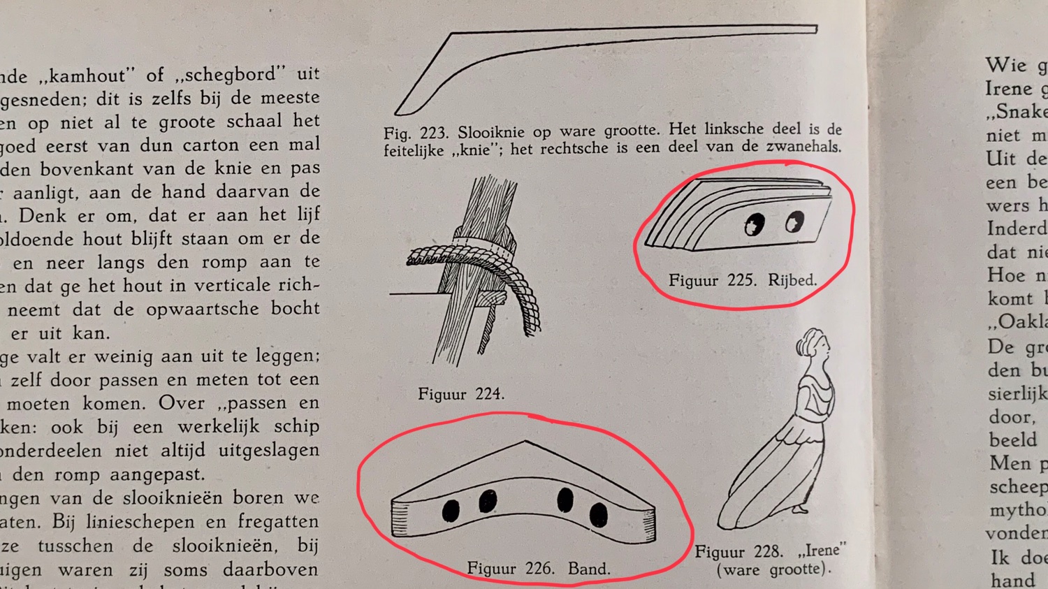
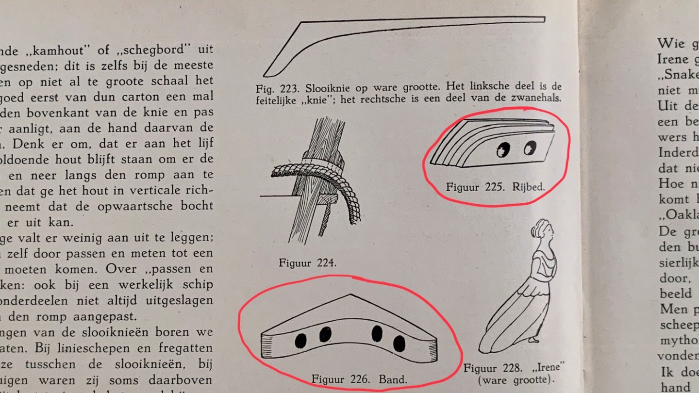
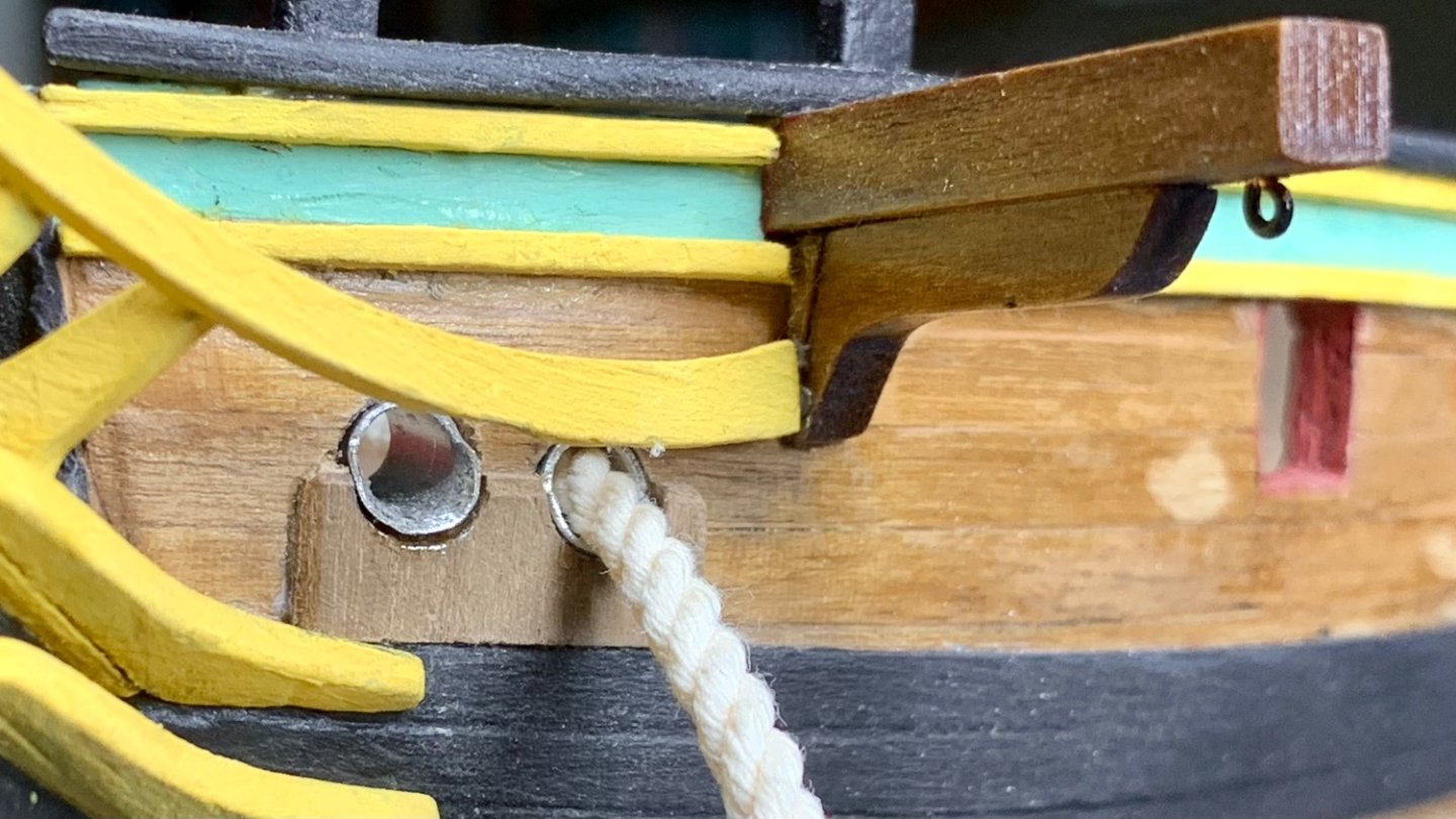
Another bit of inspiration from Petrejus’s book on the brig Irene made me try to improve the hawse holes. Until now, I just had drilled very small holes as ‘place holders’. Digging up the anchor cable of the kit (my first opening of the bag with rigging threads—a sign of progress 😉), it proved to need a 4 mm diameter hawse hole. Petrejus gave me three points of improvement. First, to protect the ship’s hull from chafing by the heavy cable, the planking would need protection, both outside (fig. 225 in the copy from Petrejus’s book, below) and inside the bulwark. Second, the inside strengthening also served as a band to keep starboard and port sides of the bulwark together (figure 226). Third, the inside of the hawse holes was clad with metal, again for protection but also to reduce friction. For point 1, it was easy to take a scrap bit of material from the 1.5 mm sheet of walnut wood containing the cut-out parts and glue it to the hull, resting on the main wale. For point 2, initially I shaped a block of wood in about the form of fig. 226, but to fit around the protruding bit of the keel above the deck and with the needed height of about 8 mm, it became such a massive thing that I abandoned it. Slightly simpler, I made 4 mm thick plates (again from scrap bits of the kit material), which together with that bit of the keel above deck might simulate Petrejus’s band. Finally, point 3 led me to buy a piece of aluminium pipe at the local model building shop. With an inner diameter of 4 mm, the outer diameter became 5 mm. Quite a big hole needed to be drilled in the hull! Isn’t it oversized? But given the size of the anchor cable, there was no other option, so here goes… Drilling and filing to get smoothly-fitting holes for the aluminium pipe was nervous stuff, and of course I did not get the hawse holes located as symmetrical and exactly-fitting as I had wanted. ‘Museum quality’ is hard to reach! But I did it and it works. Yes, the red paint needs repairing, as does the ochre paint of the bow rails, but at least those are still whole and in place. I’ll also experiment on a bit of left-over aluminium pipe (lots of it left over!) to find out how best to get a more greyish sheen on it, to resemble iron or lead. Probably I’ll end up painting them.

-
Thanks, Allan, for your historical reference. Knowing the conservativeness of Dutch shipwrights in the 18th century, I might assume they had not necessarily abolished shot garlands when this ship was outfitted as a privateer, in 1781. Moreover, the senior captain of the little squadron (there were two privateers, operating in tandem) was an old, very experienced man, which is another reason to expect an old-fashioned deck lay out (more like mid-century, when he was young). So I might go for shot garlands, but then placed on the bulwarks (Chris Watton suggested that to me), while keeping the binding strakes free for the rings. Thanks, too, for teaching me the correct translation of ‘schaarstokken’ as ‘binding strakes’—neither my old school dictionary nor Google Translate had that, and even in Patrick O’Brian’s Aubrey/Maturin novels I had not come across the term 😊
-
Many thanks for this suggestion, Chris! Shows once more that if you think you’ve got a dilemma, you haven’t been thinking creatively. I like especially the ‘window sill’ idea, putting them in between gun ports. The calibre of the guns on this brig was not too large, the cannon balls not too heavy (9 or 12 pounders? I should look it up, one of these days) so it would have been quite feasible to put them there.
-
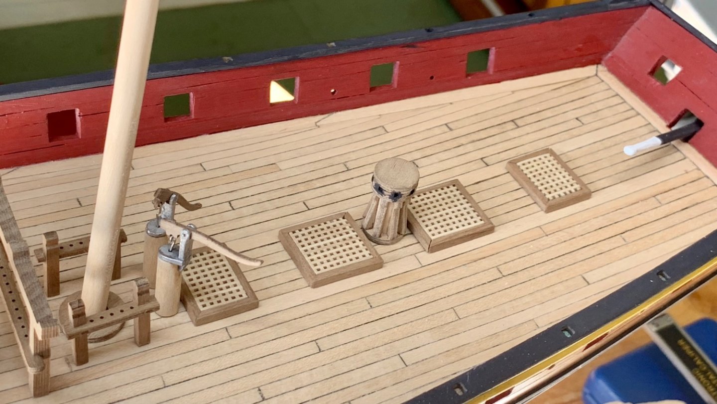
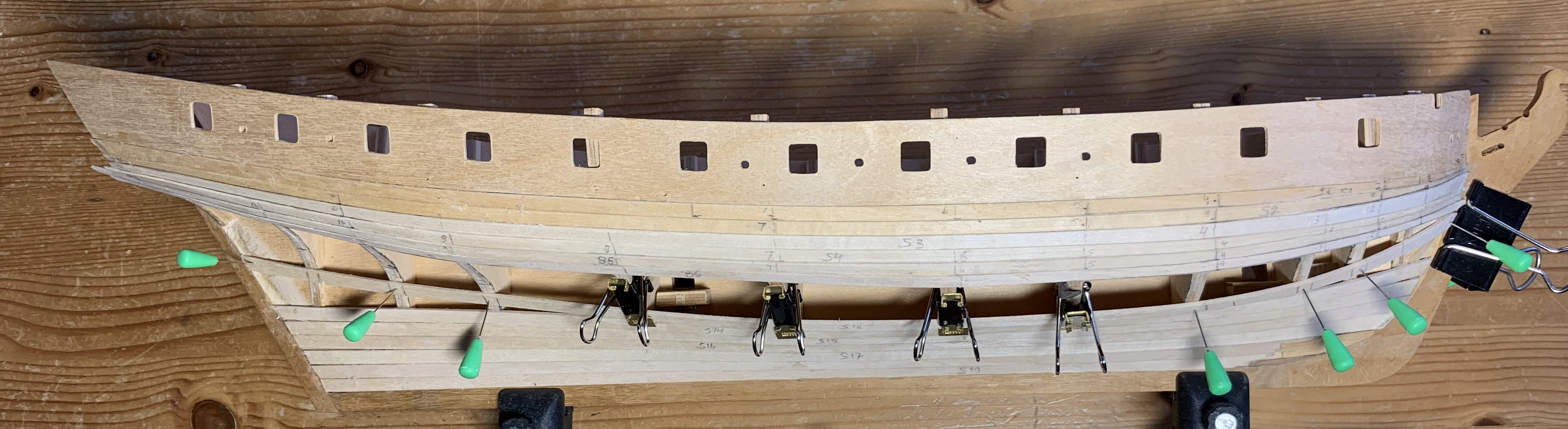
The deck of my Dutch 1780s privateer ‘Mars’ starts to look neat, with the hatches, gallows, pumps etc. But there is a dilemma: should I add shot garlands around the hatches, or should I reserve the ‘continental king planks’ (‘schaarstokken’ in Dutch, a little wider and thicker than normal deck planks) that run along the hatches for the ring bolts that must come behind each gun? On the one hand, the Caldercraft model I am building does not include shot garlands, but such things are included in similar models, like Vanguard Models’ HMS Speedy, and they are also depicted in the Petrejus book about the (English-built) Dutch brig ‘Irene’ as normal elements on fighting ships of the time. On the other hand, those ‘king planks’ were extra sturdy precisely to give ring bolts a secure place. And I cannot have my cake and eat it too, as shot garlands take up almost 4 mm of width while those ‘king planks’ are 5 mm wide, so there is not enough place left to put en eyelet in. So if I add shot garlands, eyelets must be fastened to ‘normal’ deck planks. I should like the result to look as authentic as I can make it. What advice would you give, dear shipwrights?

-
Advice sought: shot garlands or ring bolts? The deck starts to look neat, with the hatches (easy little job!), gallows, pumps etc. All except the hatches are just placed temporarily, because I’ll paint them first, safely away from the hull. But there’s a dilemma: should I add shot garlands around the hatches, or should I reserve the continental ‘king planks’ that run along the hatches for the ring bolts that must come behind each gun? On the one hand, the Caldercraft model does not include shot garlands, but such things are included in similar models, like Vanguard Models’ HMS Speedy, and they are also depicted in the Petrejus book about the brig Irene. On the other hand, those ‘king planks’ were extra sturdy precisely to give ring bolts a secure place. And I cannot have my cake and eat it too, as shot garlands take up almost 4 mm of width while those ‘king planks’ are 5 mm wide, so there is not enough place left to put en eyelet in. So if I add shot garlands, eyelets must be fastened to ‘normal’ deck planks. What advice would you give, dear shipwrights?