ships88
-
Posts
77 -
Joined
-
Last visited


-
 Scottish Guy reacted to a post in a topic:
Greek Trireme by ships88 - Dusek - 1:72
Scottish Guy reacted to a post in a topic:
Greek Trireme by ships88 - Dusek - 1:72
-
Scottish Guy reacted to a post in a topic:
Greek Trireme by ships88 - Dusek - 1:72
-
Scottish Guy reacted to a post in a topic:
Greek Trireme by ships88 - Dusek - 1:72
-
Scottish Guy reacted to a post in a topic:
Greek Trireme by ships88 - Dusek - 1:72
-
Scottish Guy reacted to a post in a topic:
Greek Trireme by ships88 - Dusek - 1:72
-
Scottish Guy reacted to a post in a topic:
Greek Trireme by ships88 - Dusek - 1:72
-
Scottish Guy reacted to a post in a topic:
Greek Trireme by ships88 - Dusek - 1:72
-
Scottish Guy reacted to a post in a topic:
Greek Trireme by ships88 - Dusek - 1:72
-
Scottish Guy reacted to a post in a topic:
Greek Trireme by ships88 - Dusek - 1:72
-
Scottish Guy reacted to a post in a topic:
Greek Trireme by ships88 - Dusek - 1:72
-
ships88 reacted to a post in a topic:
Mary Rose by Mr Pleasant - FINISHED - Caldercraft - 1:80
-
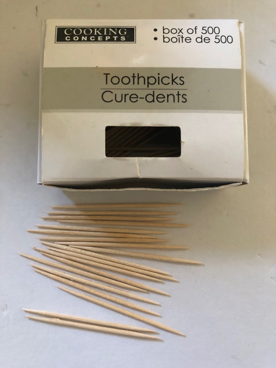
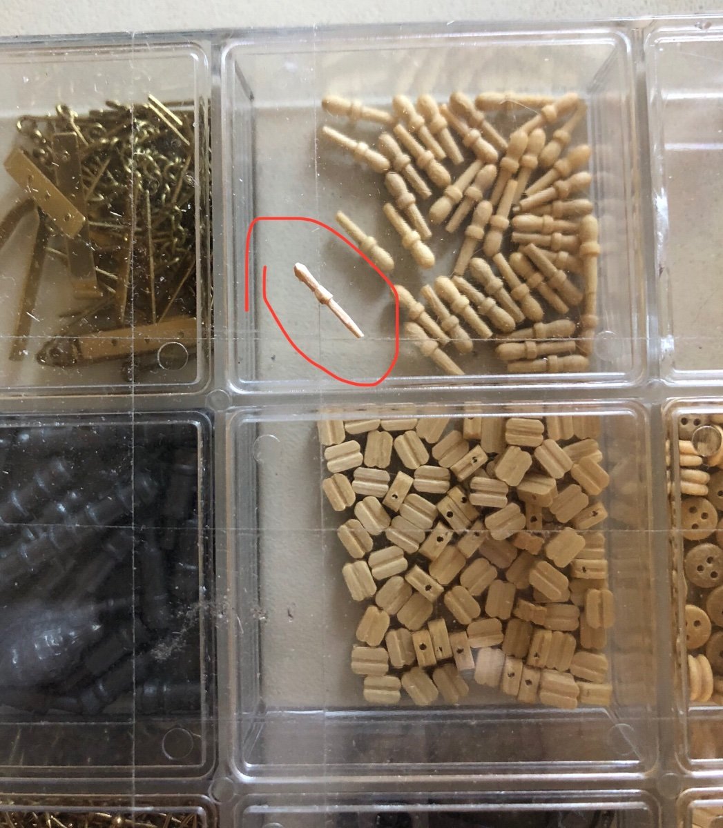
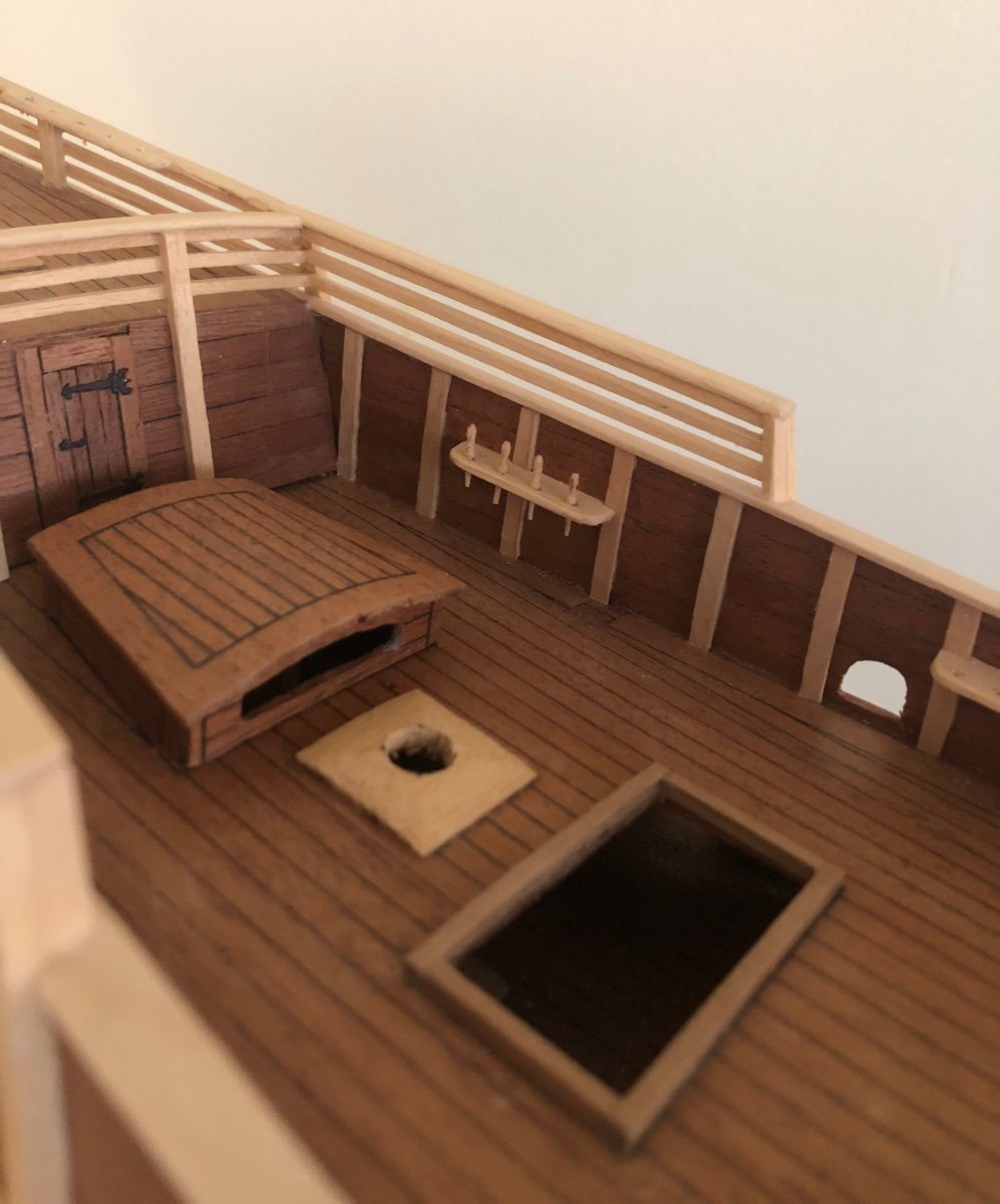
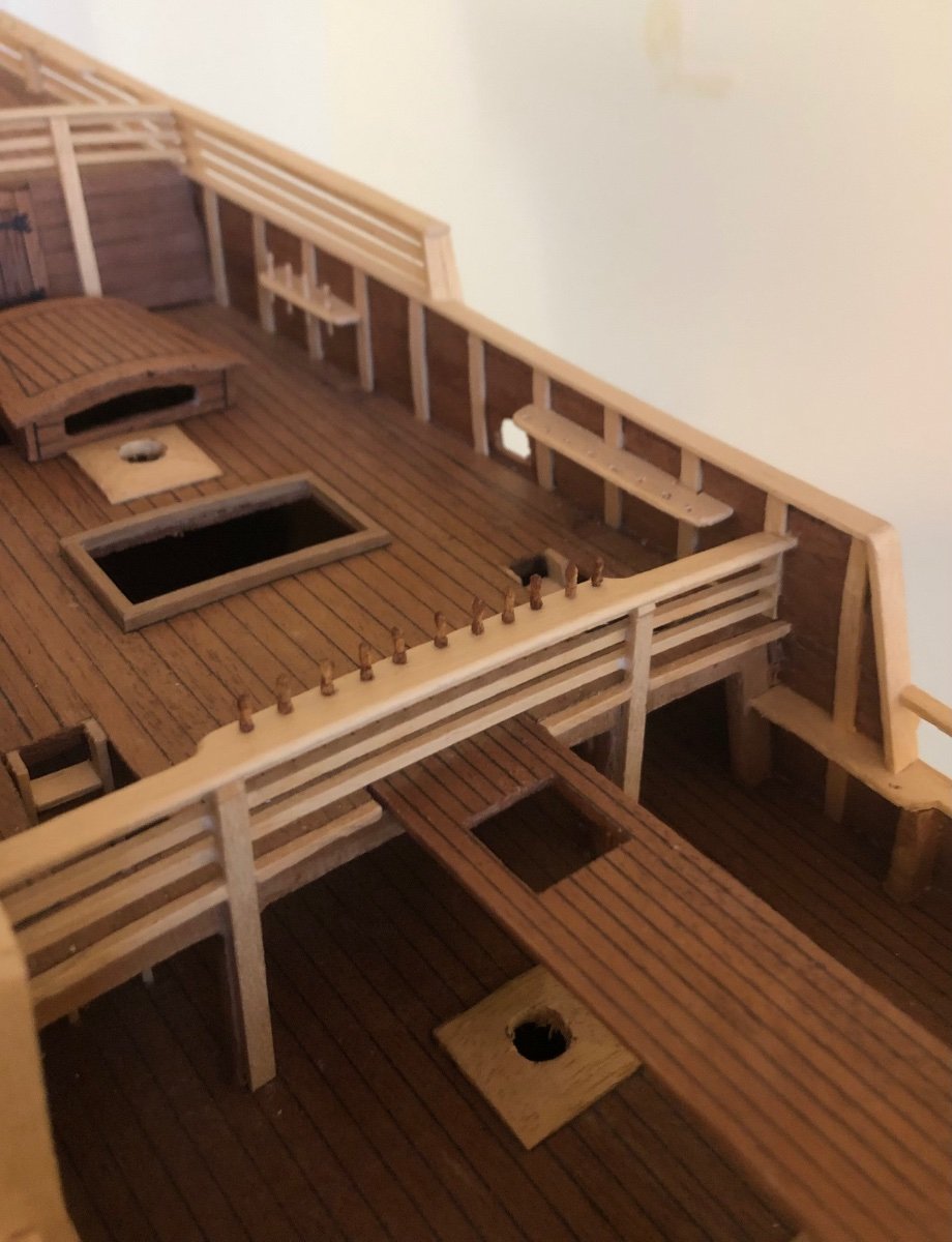
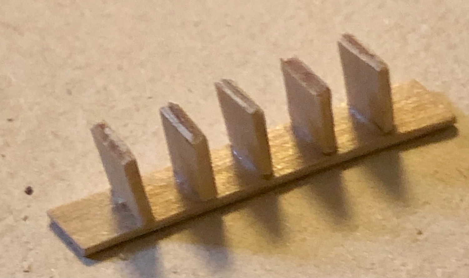
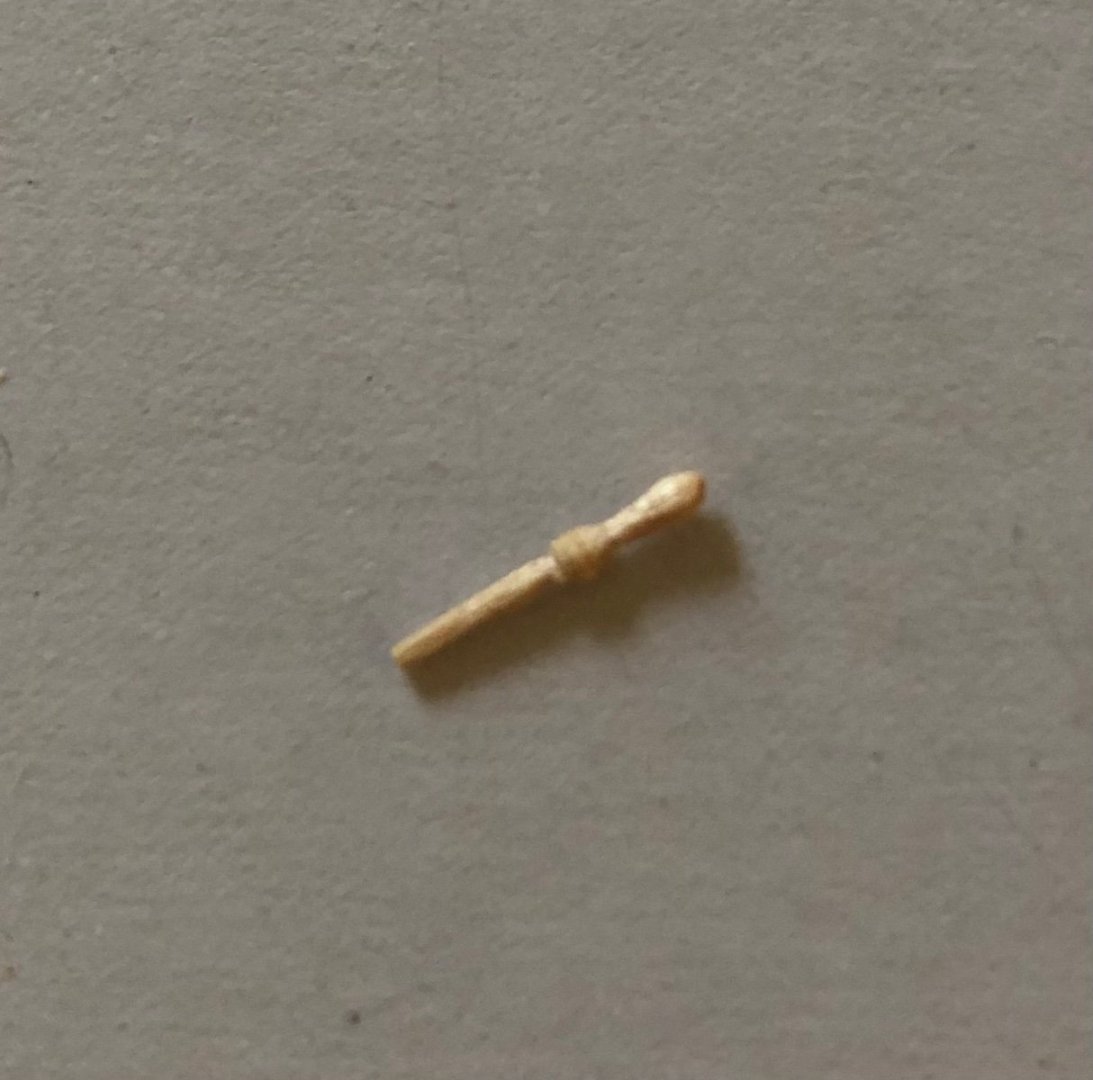
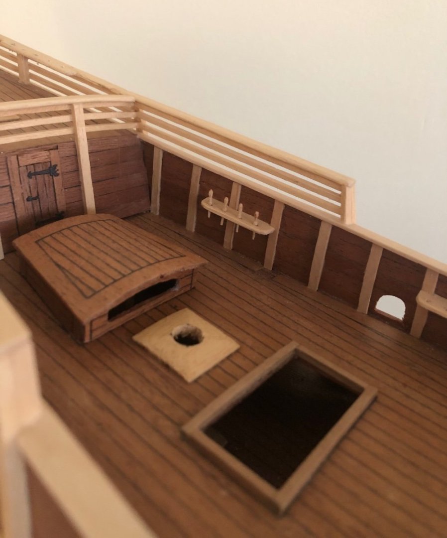
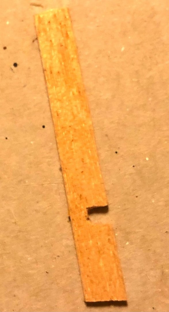
 Getting back to the build after a long break. I paused because I didn’t have the fitting (belaying pins, dead eyes,, etc) and don’t love what is available on the market either (out of scale, incompatible with galleon of the time and too expensive). Figure to tackle the belaying pin first. Decided to make 10 mm pin with =~ 1mm diameter (the plan’s belaying pin holder opening is 1 mm). It fits the convention standard. toothpicks turns out to be a great material option. It comes in a 500 per box for $1.25 at Dollar tree store. The toothpick’s wood characteristics, shape and size is ideal for this purpose. A Belaying pin made from toothpick (took about 5 minutes total) A size comparison to the Occre fitting set’s belaying pins for the Golden Hind (1/85 scale) Test fitting couple of the handmade pins onto the rack. Looks like good fit and scaled well. Test fitting pins that were stained darker (instant coffee works great) to better shows contrast w the rail color. This galleon requires a ton of belaying pins. Time to make more,,,, PS. If there are interests to seeing the pin creation process, let me know and i will post the step by step illustrations.
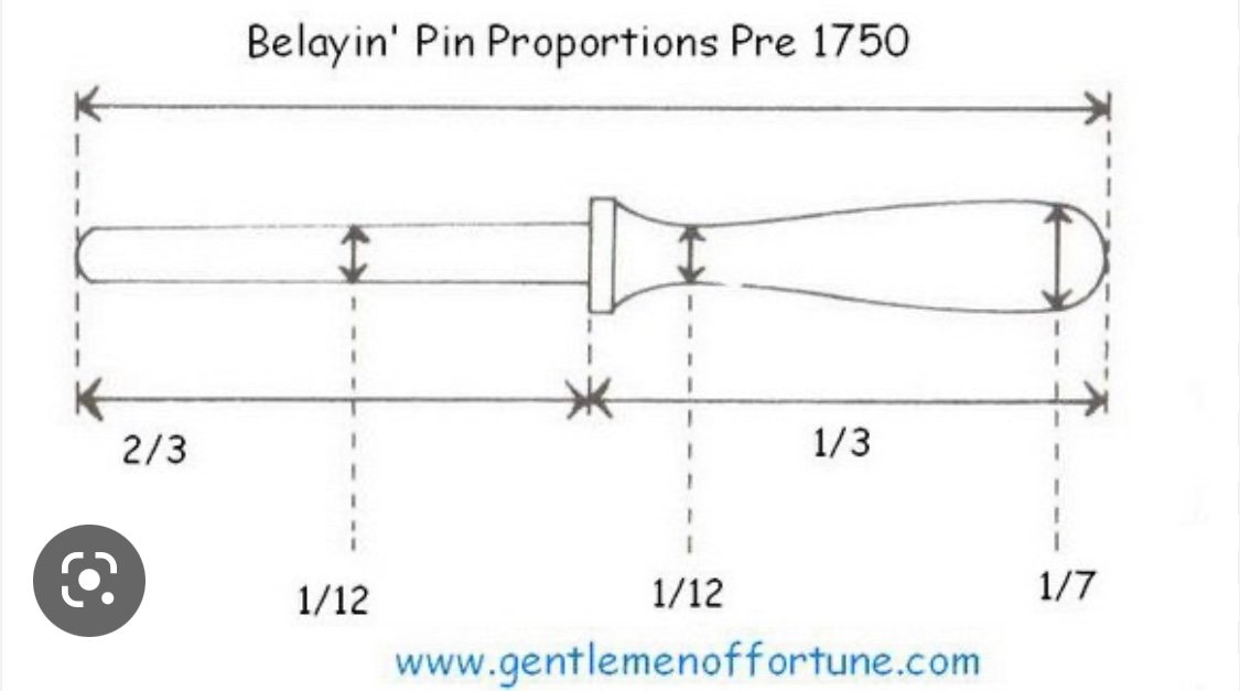


- 58 replies
-
- 7
-
-
- Spanish galleon
- Billing Boats
- (and 1 more)
-
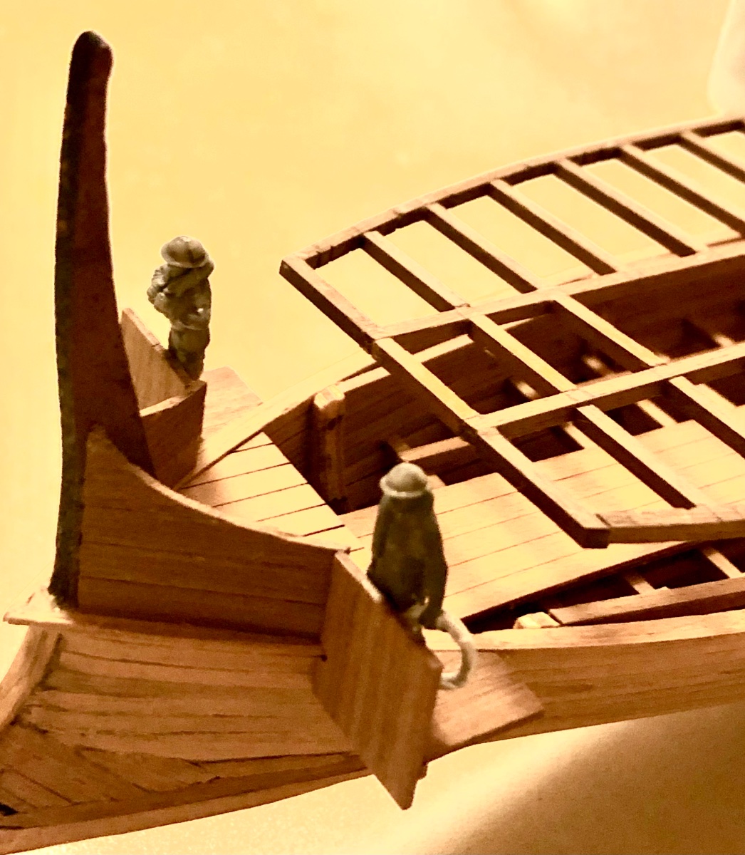
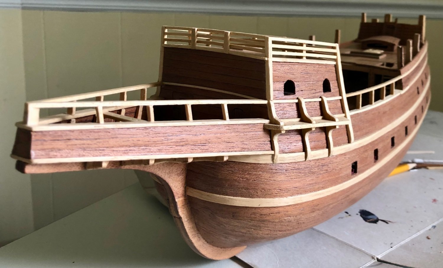
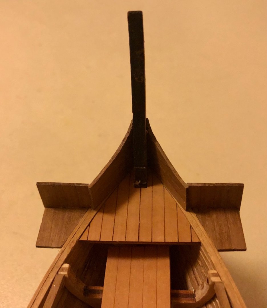
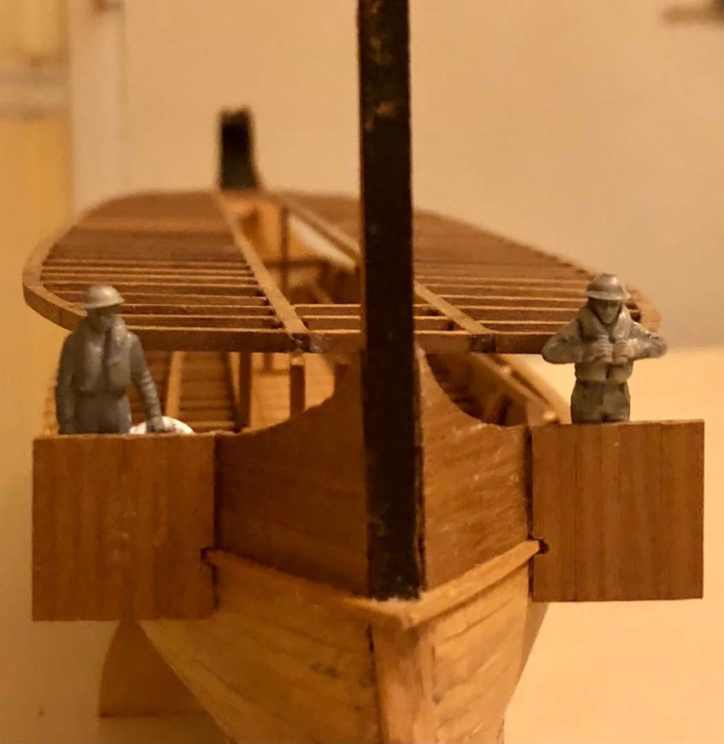
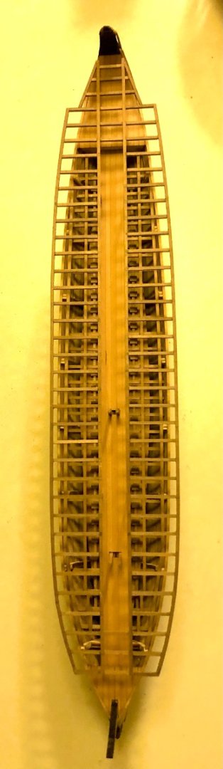
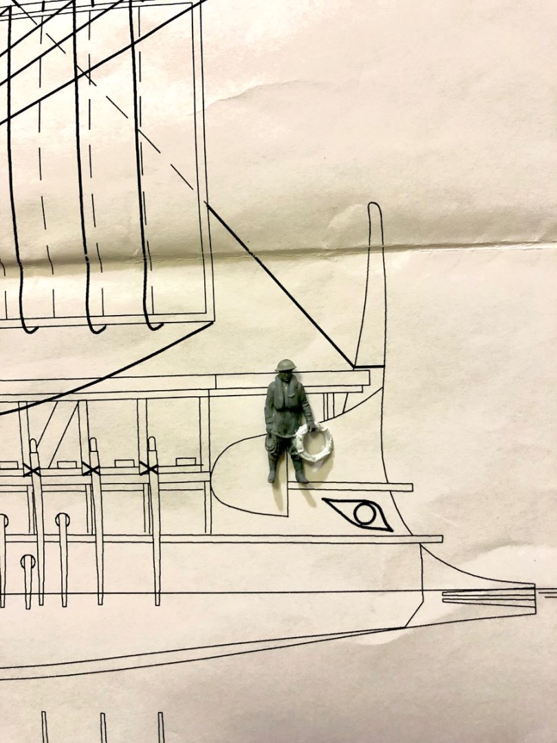
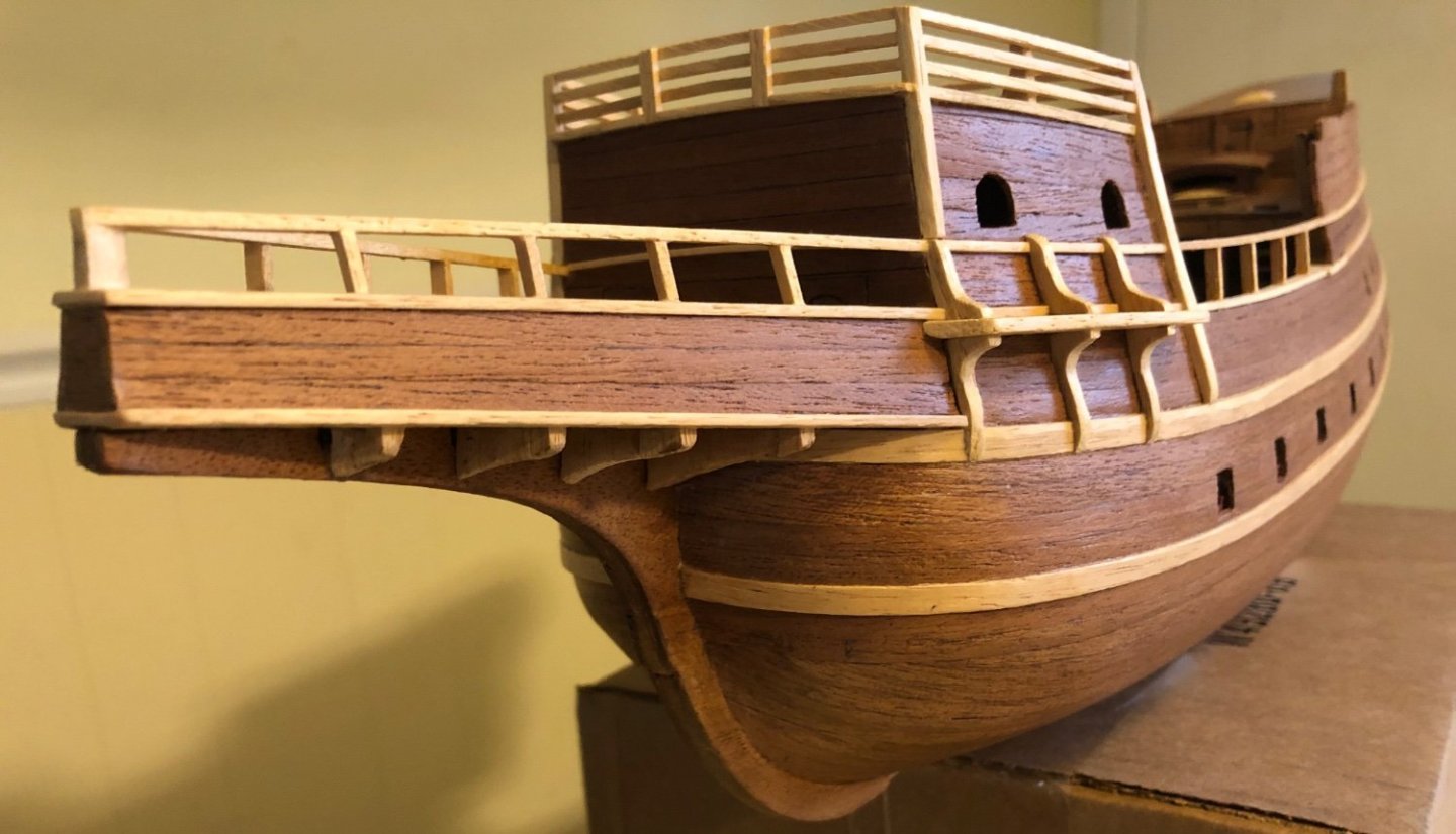
Added the upper wale to the hull, which enabled the frontal platform to be installed. The 1/72 scale Royal navy figures clearly shows the overhang deck cover to the bow post is not possible/ feasible.
-
ships88 reacted to a post in a topic:
La Real by Rossi46 - Dusek - scale 1/72
-
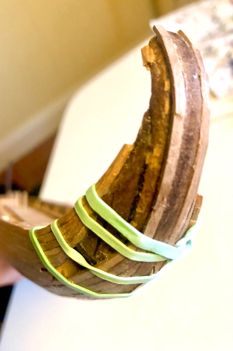
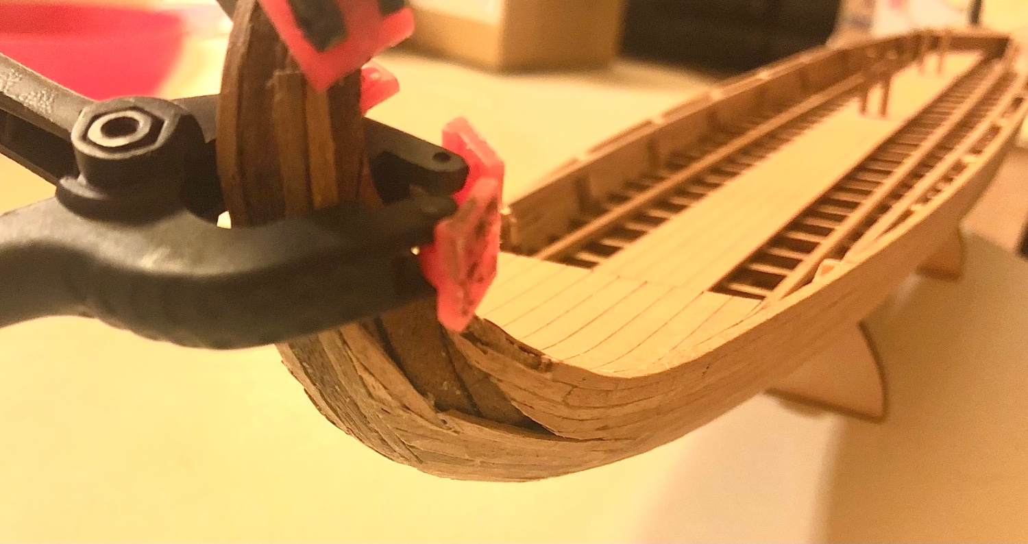
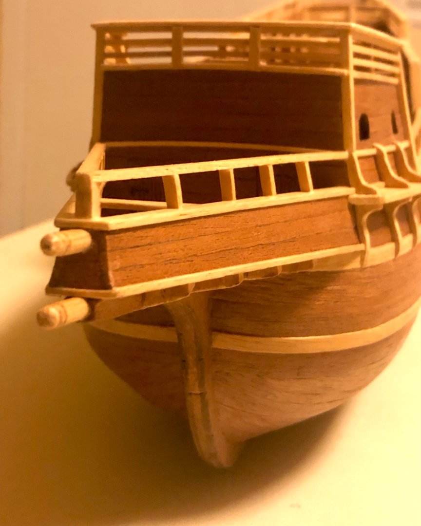
The most challenging aspect of this build is the curve stern. I really didn’t have any good idea how to go about it and put off tackling it for a long time. The build now can’t progress without completing the stern first. The kit supplied 2 x 2mm walnut plankings are impossible to bend (even after soaking in water for hours). I ended up splitting those planks down to 1 x 2mm, bend them where ever possible and build the stern with sectional plank pieces to make the required curvature. The end result looked decent enough after sanding.


-
ships88 reacted to a post in a topic:
Spanish Galleon by ships88 - Billing Boats
-
ships88 reacted to a post in a topic:
Spanish Galleon by ships88 - Billing Boats
-
 ships88 reacted to a post in a topic:
Cazador Jabeque / Xebec by Katsumoto - FINISHED -OcCre - 1:60
ships88 reacted to a post in a topic:
Cazador Jabeque / Xebec by Katsumoto - FINISHED -OcCre - 1:60
-
ships88 reacted to a post in a topic:
Cazador Jabeque / Xebec by Katsumoto - FINISHED -OcCre - 1:60
-
ships88 reacted to a post in a topic:
Cazador Jabeque / Xebec by Katsumoto - FINISHED -OcCre - 1:60
-
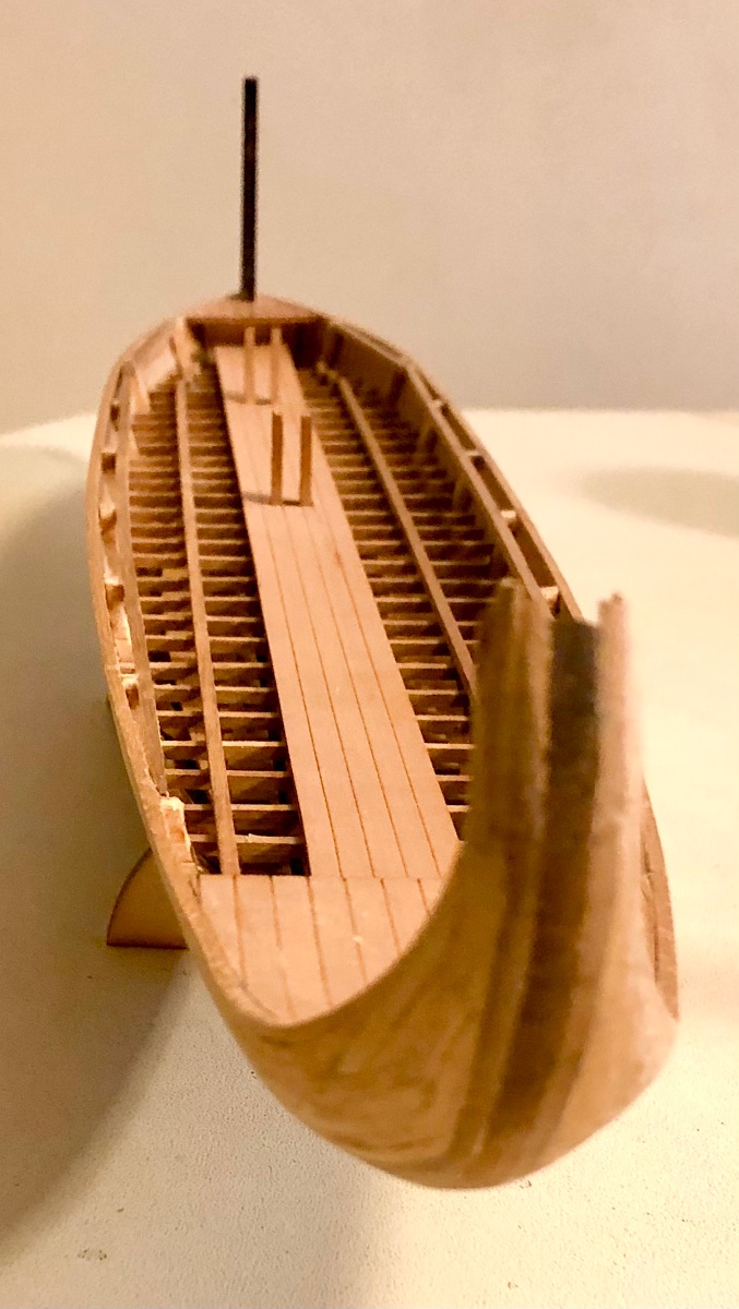
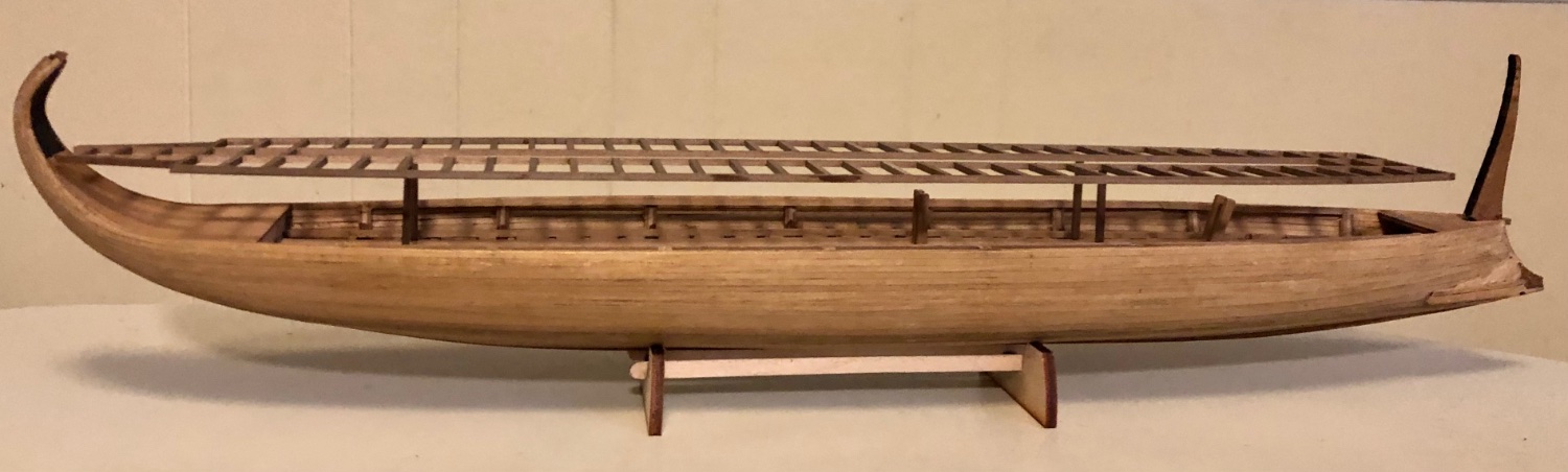
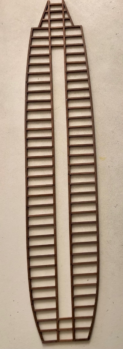
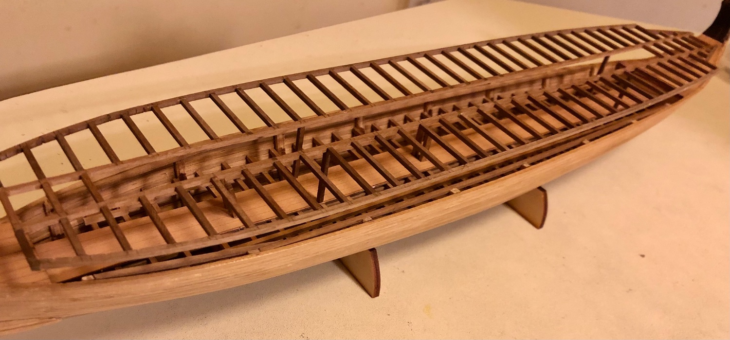
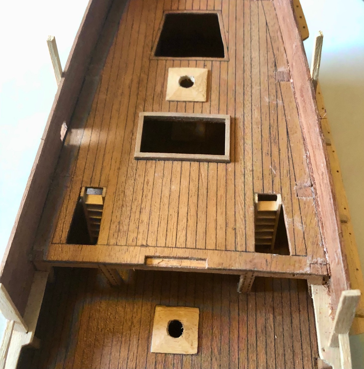
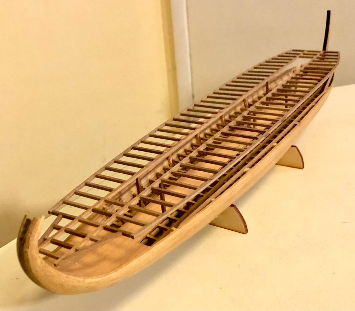
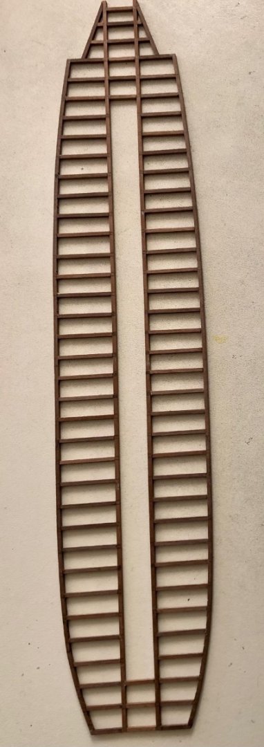
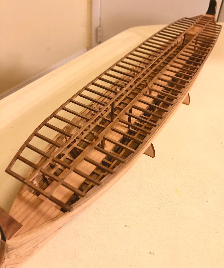
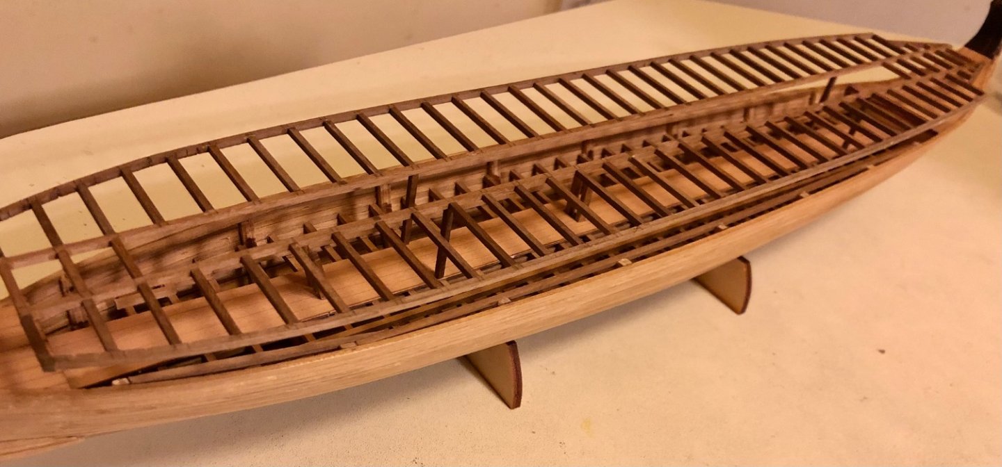
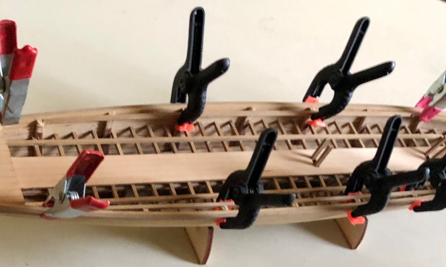
One thing about going with the hull curve shape for the deck roof versus the kit’s rectangular deck is majority of the deck rafter has to be individually cut to length to fit. This took almost 2 full days to complete. The completed deck roof frame. Test top view of the deck frame over the hull to illustrate the overhang. Using 4 temp vertical support beam (according to plan heigh, 27mm) to check the fit. Another closer view. A lot more vertical support posts to cut,,, Going to take awhile.
-
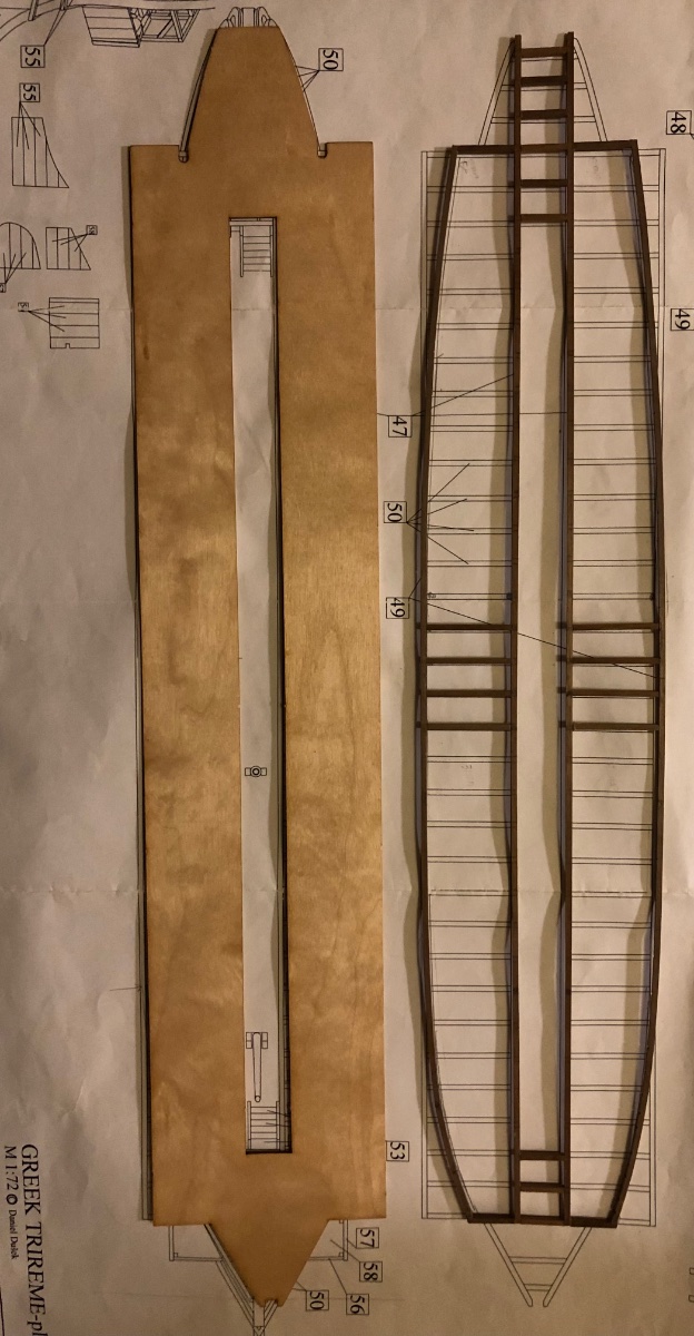
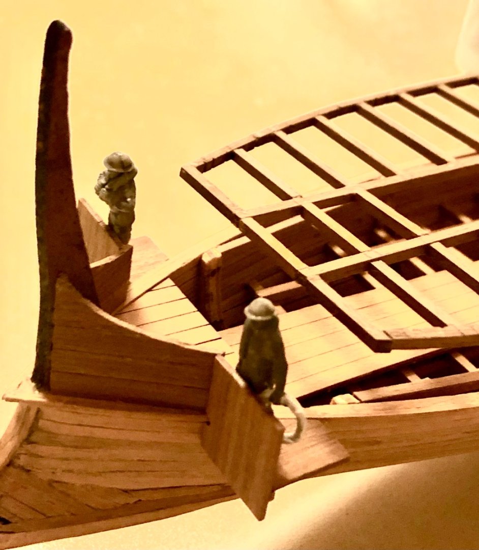
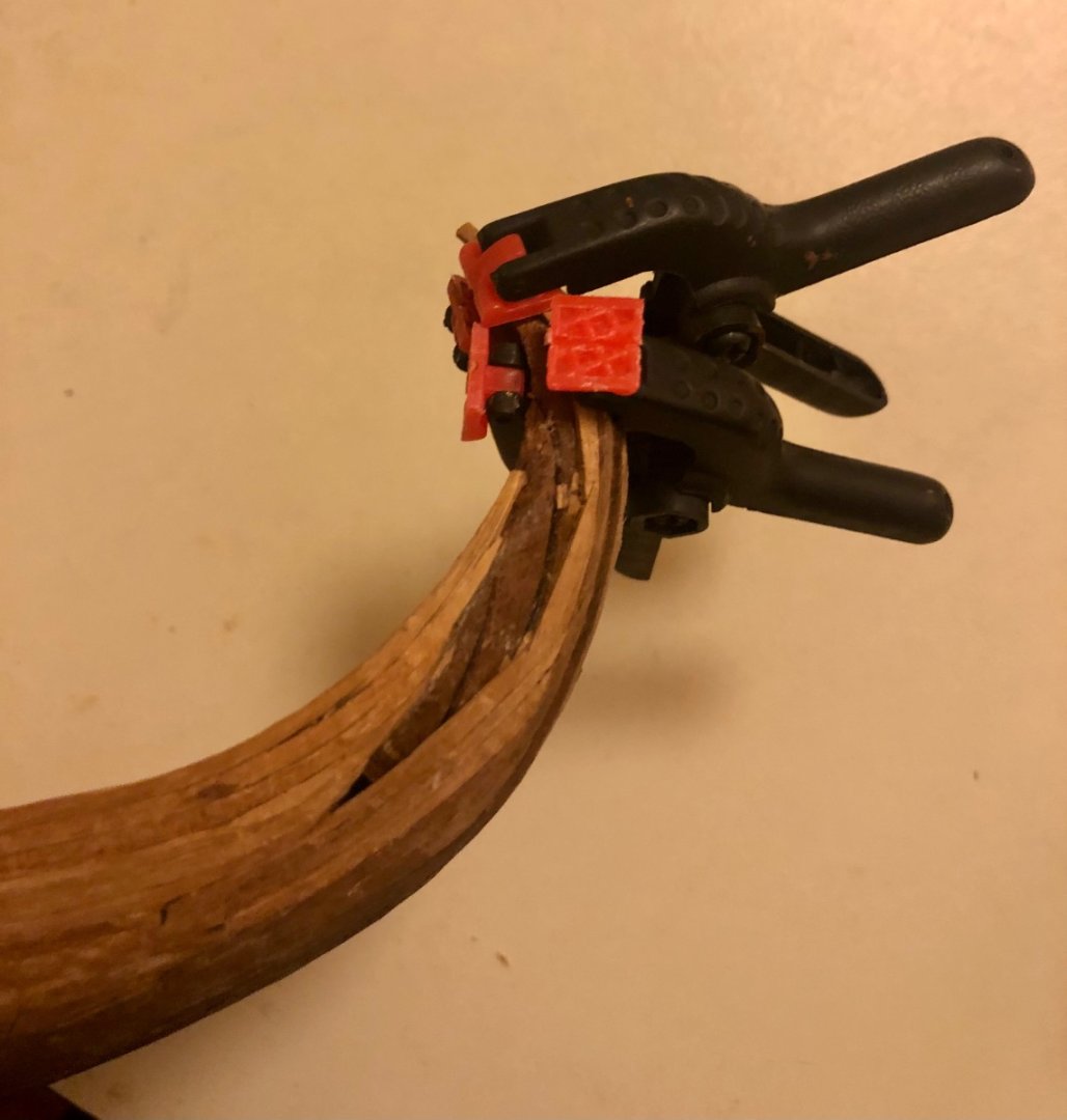
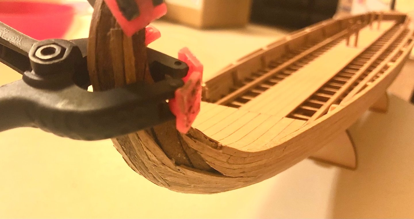
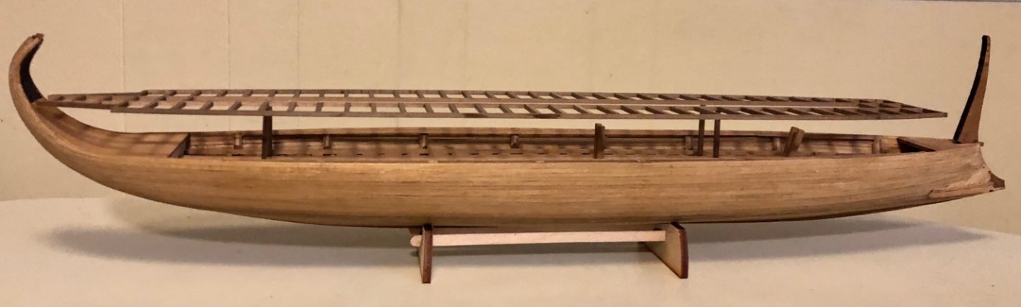
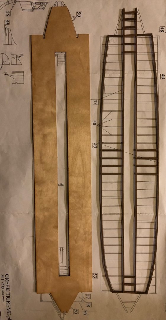
Getting back the build and taking a break from my Billingboats Spanish galleon build https://modelshipworld.com/topic/30191-spanish-galleon-by-ships88-billing-boat Using the 1/72 Airfix RAF rescue launch kit’s crew figure to gauge if the covered top deck to the bow is feasible/ realistic. Looks like it is not. Decided to use the hull curve for the basis the deck roof shape instead of the kit provide rectangular deck (wet the 2x2mm stakes and clamped). A side by side comparison. The curve deck form difference against the plan’s drawing clearly visible. What do you guy think ? Better or should I use the kit’s rectangular deck form (this shape doesn’t make sense to me for a ship using ramming as a primary weapon. The front would protruding too far out and get stuck to the enemy ship after the attack)
-
ships88 reacted to a post in a topic:
L'Ambitieux by Nek0 - Altaya
-
ships88 reacted to a post in a topic:
L'Ambitieux by Nek0 - Altaya
-
ships88 reacted to a post in a topic:
L'Ambitieux by Nek0 - Altaya
-
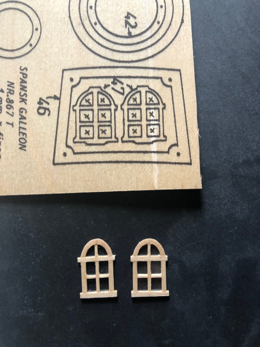
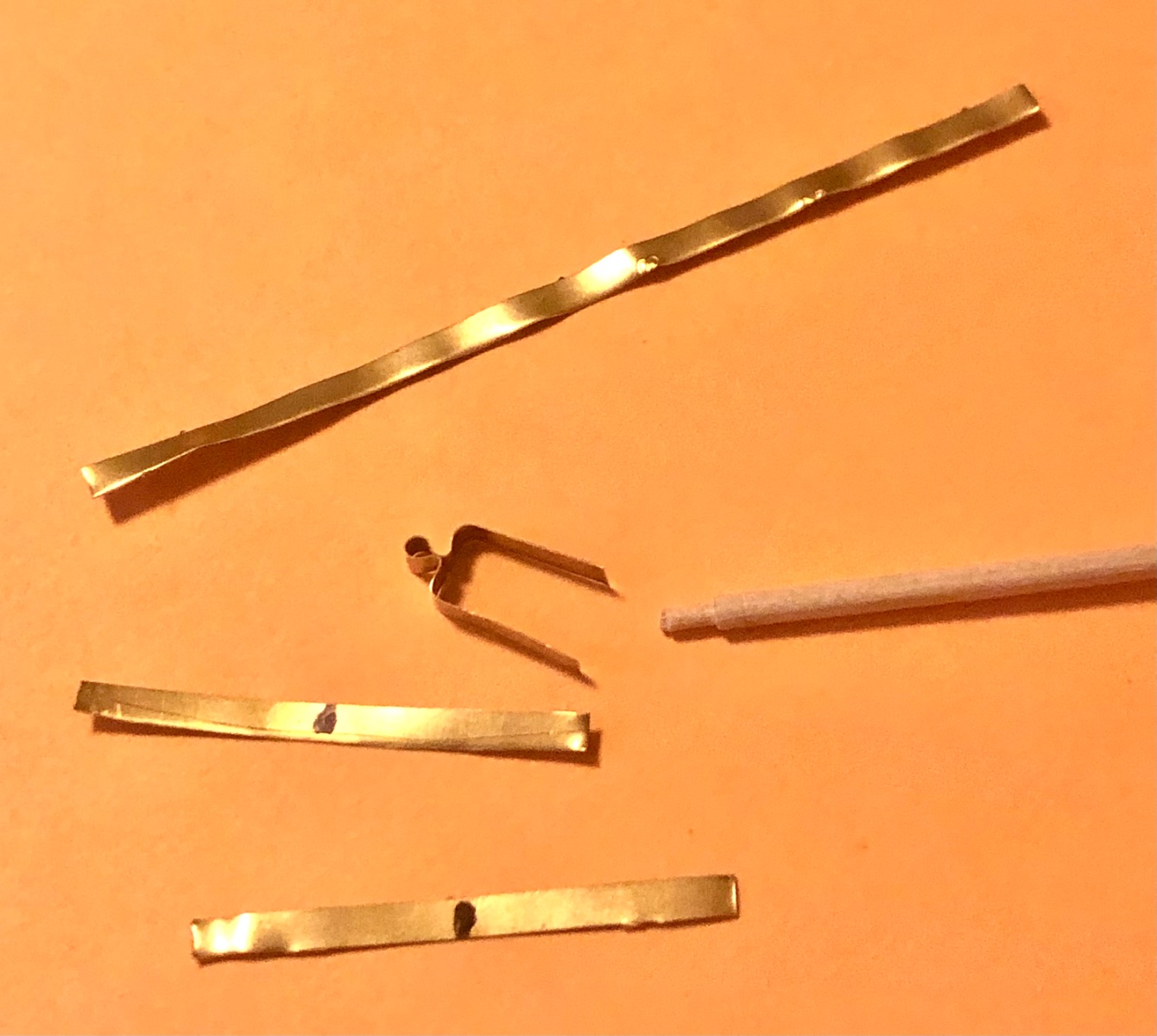
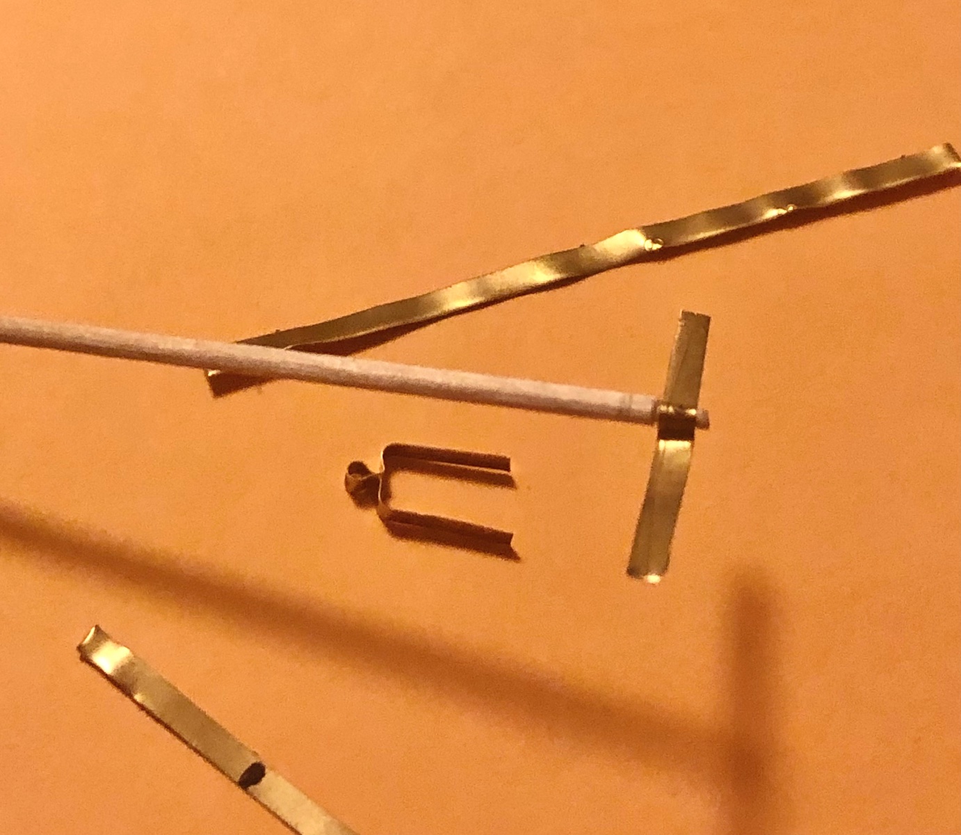
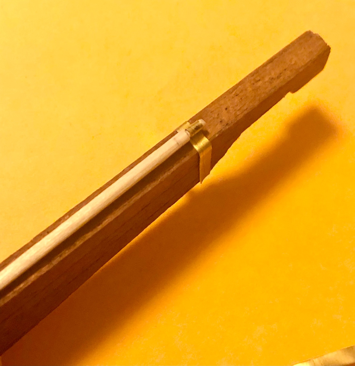
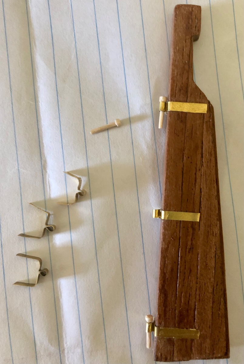
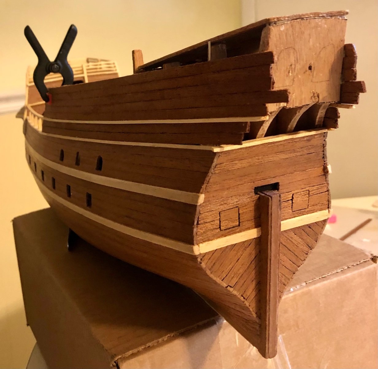
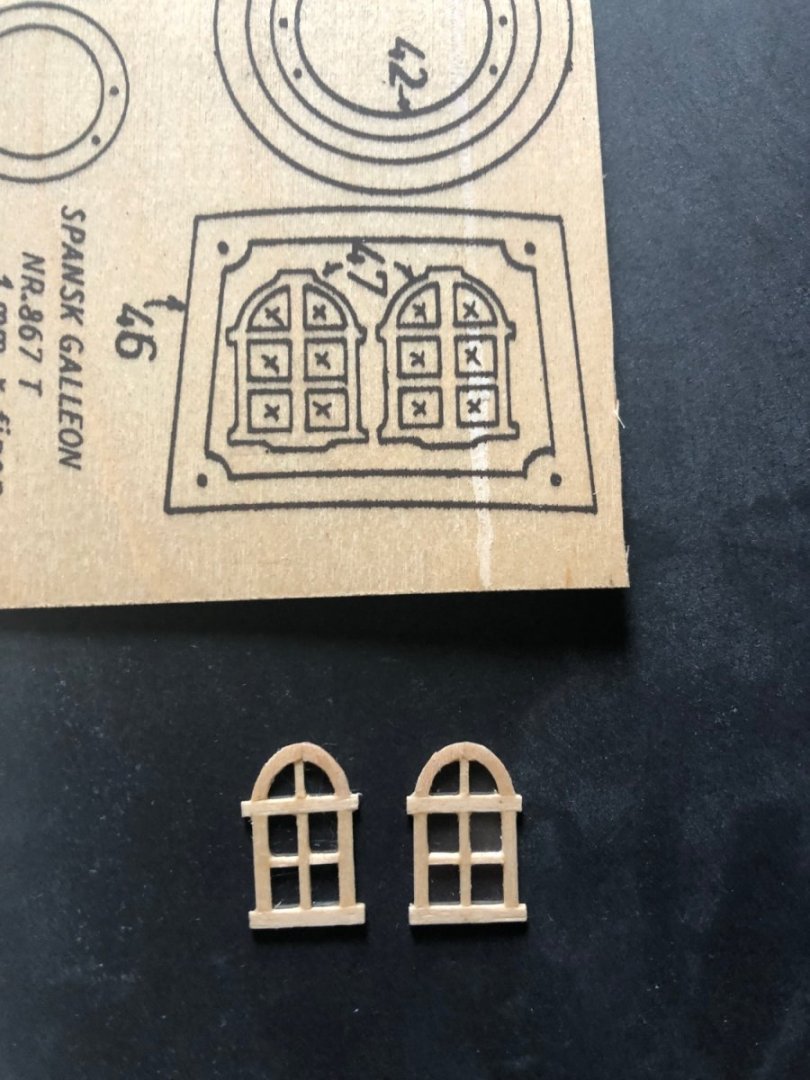
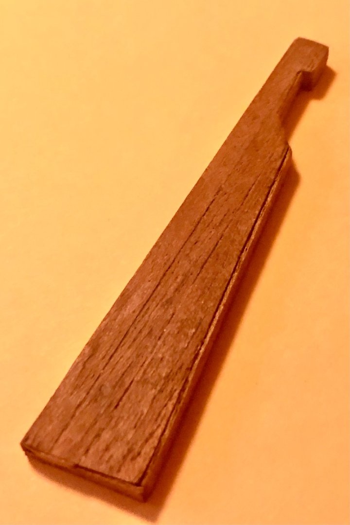
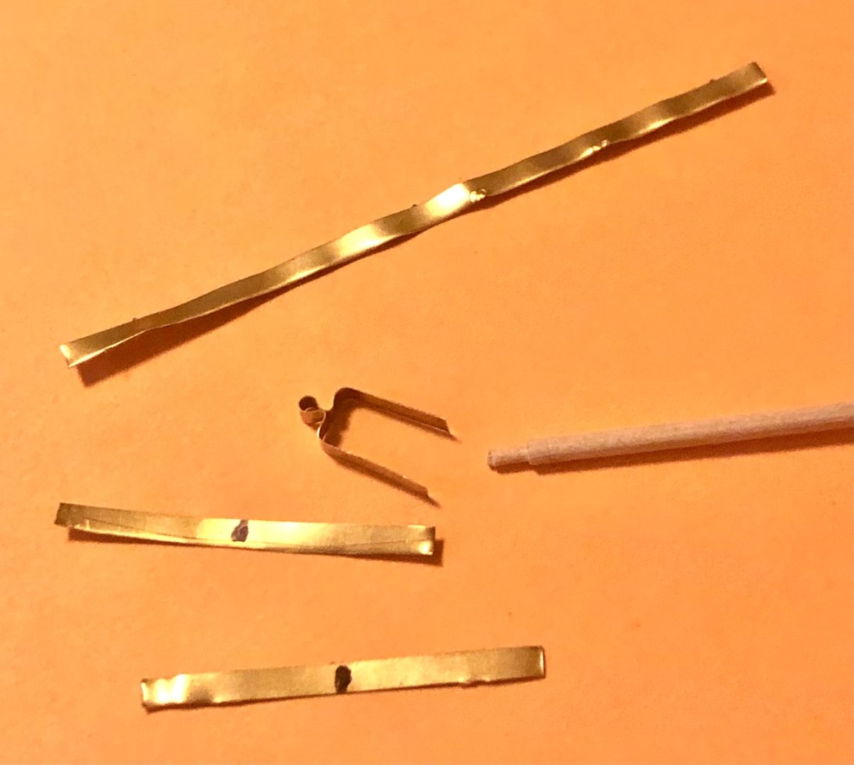
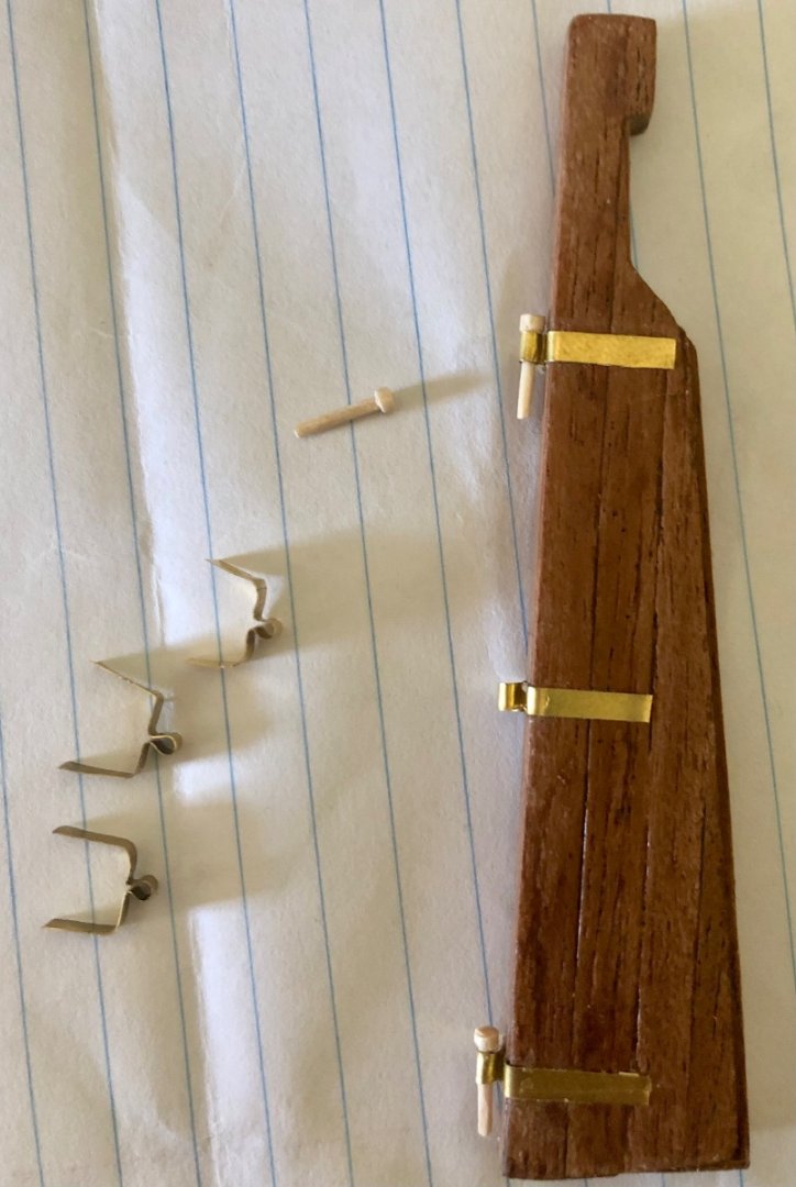
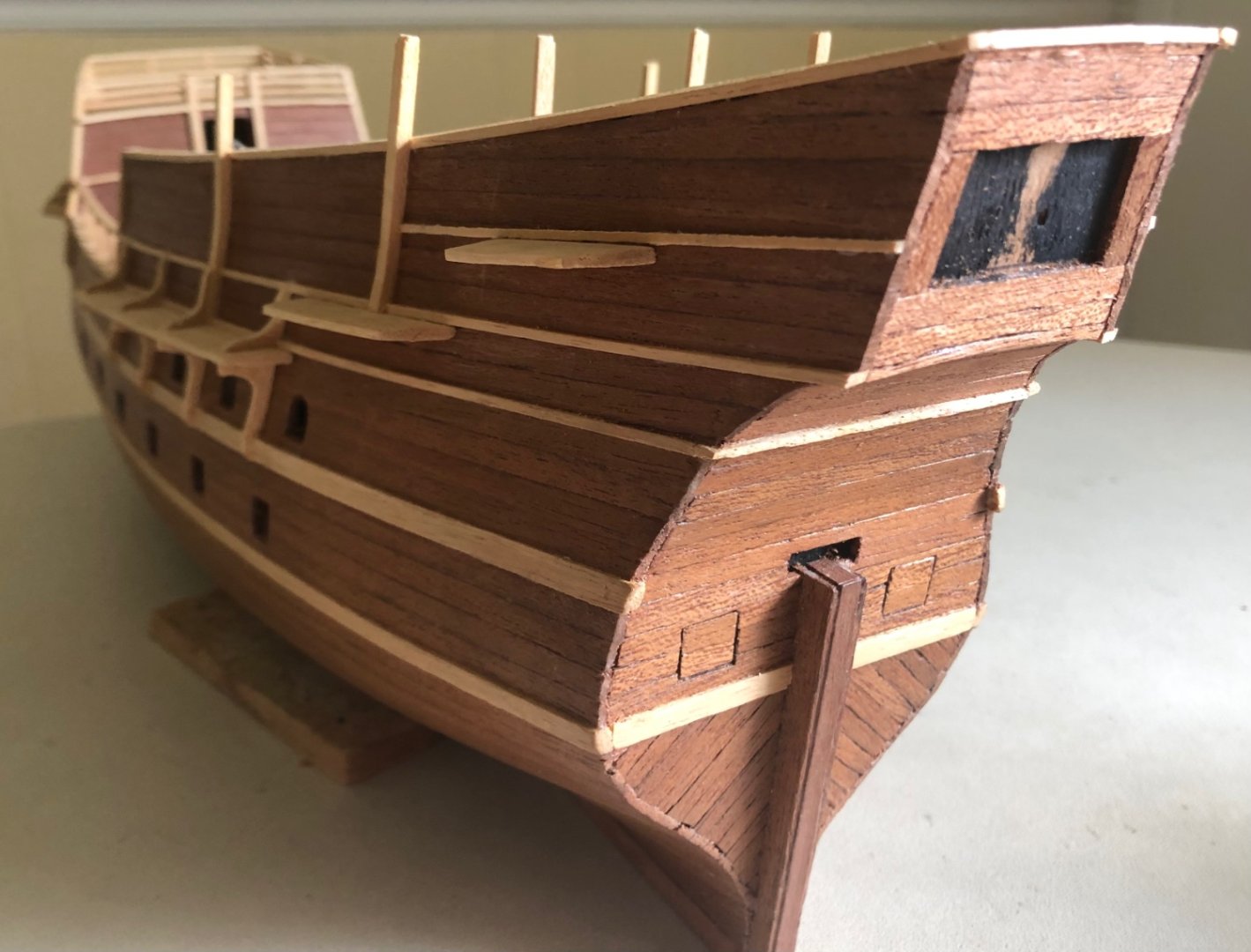
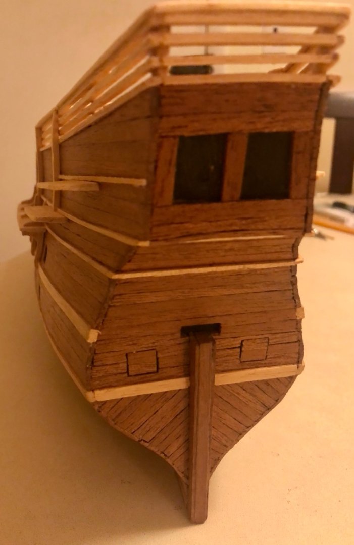
Stern windows & rudder installations The kit provided stern framing & windows on printed plywood sheet. I decided not to use them. Scratch built the window frame and fit the stern frame individually. Stern frame and windows installed. The single piece plywood rudder was covered w thinned down hull planking strips to match the hull and shows the 4 pieces of wood stock that makes up the rudder. I obtained the kit from Ebay years ago without the fittings. Making the rudder braces from scrap brass photo-etch left over from my other model kits. Using an applicator wooden shift rounded down to the correct diameter to form the eye. The partly formed bracket is then placed over the rudder then blend into shape. The same process is repeated for the stern post brackets. The cotton applicator’s wooden shaft is trimmed to make the three rudder pins. They will be painted black later. The 4 pin rails on the quarter deck and the walk way between the forecastle & quarter deck installed. Side view w rudder installed. View from The stern.


- 58 replies
-
- 8
-
-
-
- Spanish galleon
- Billing Boats
- (and 1 more)
-
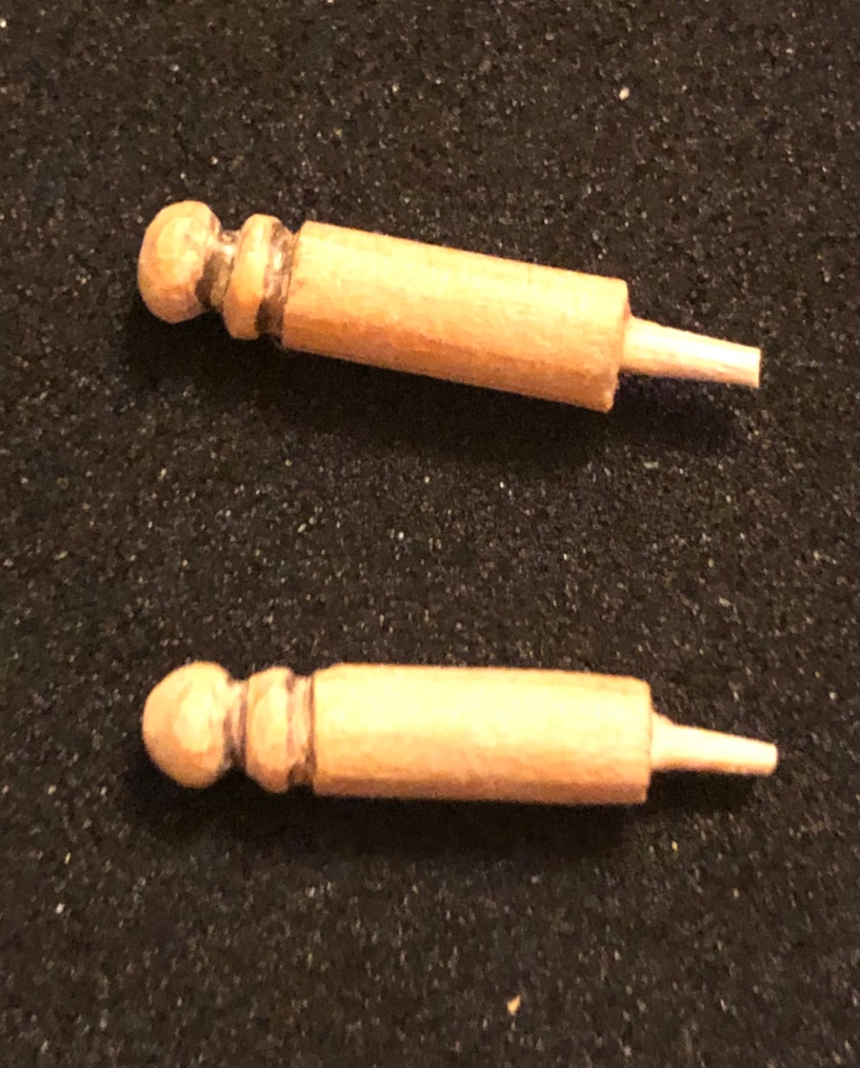
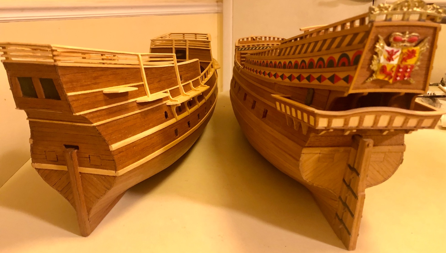
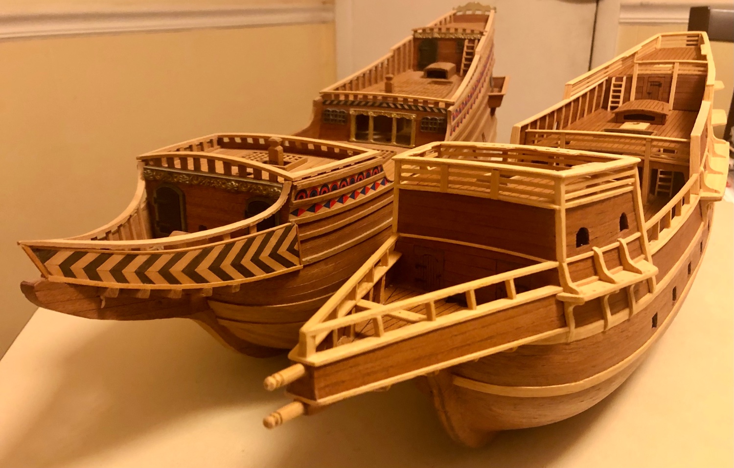
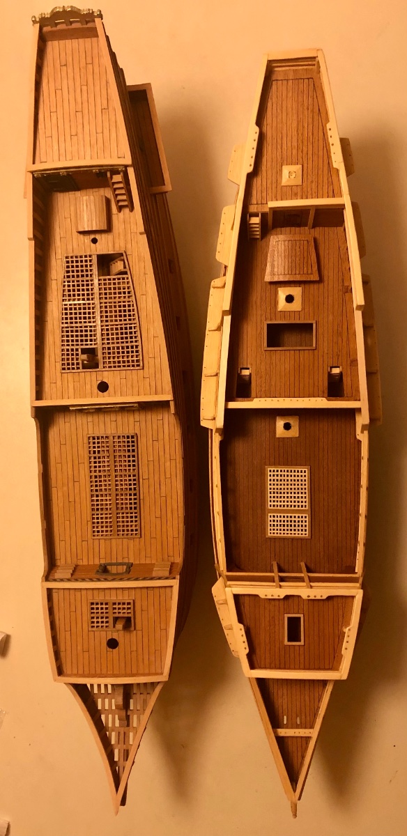
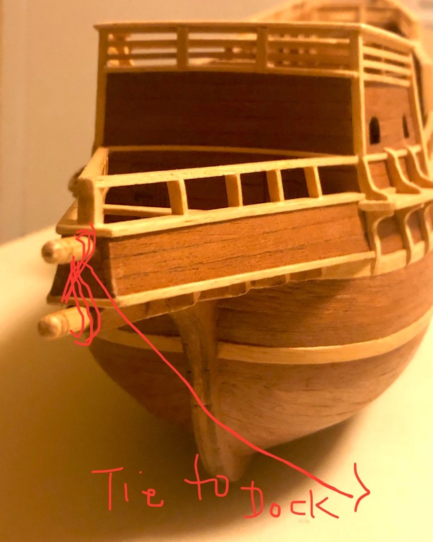
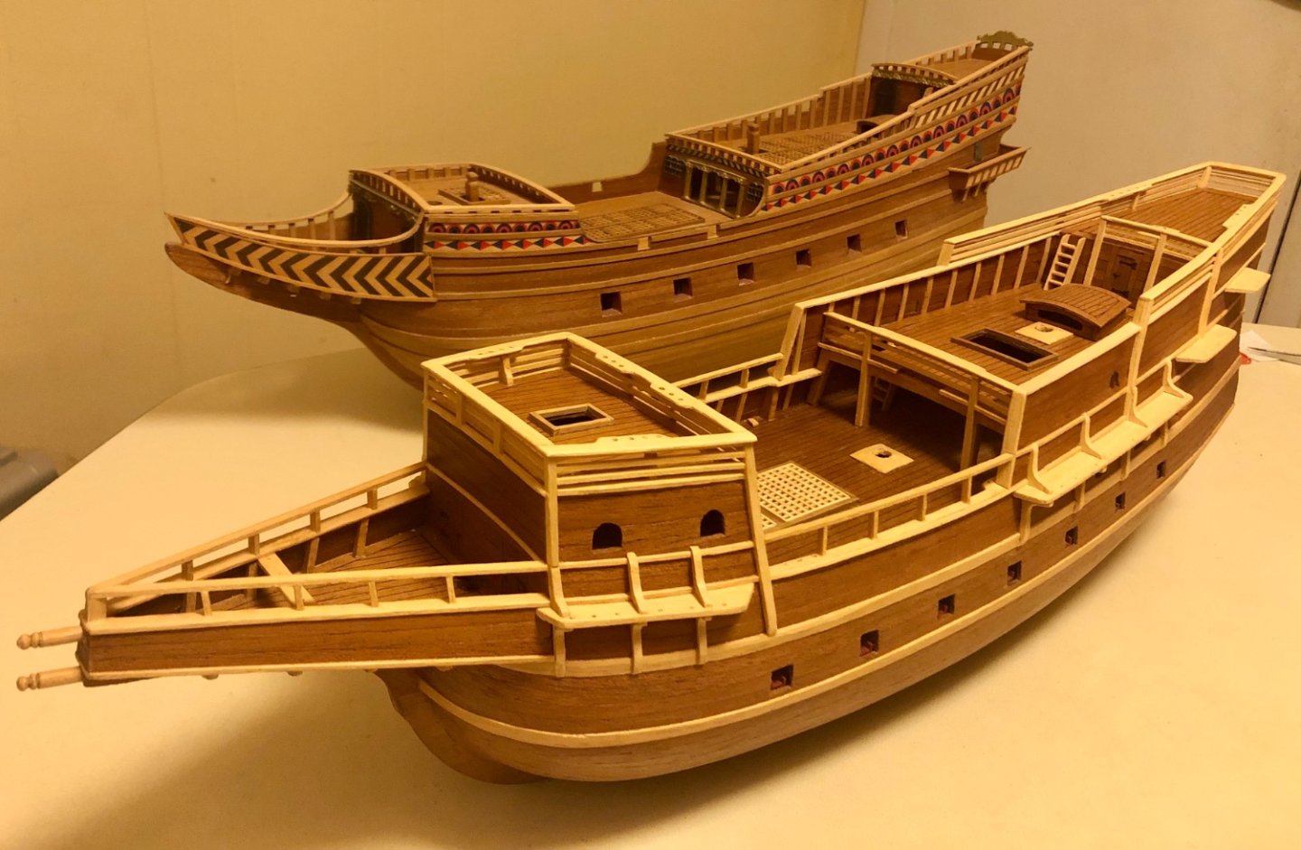
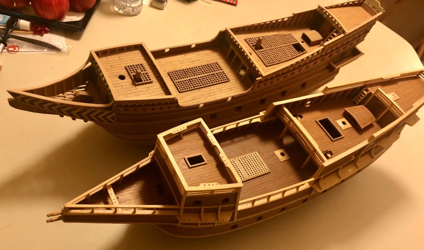
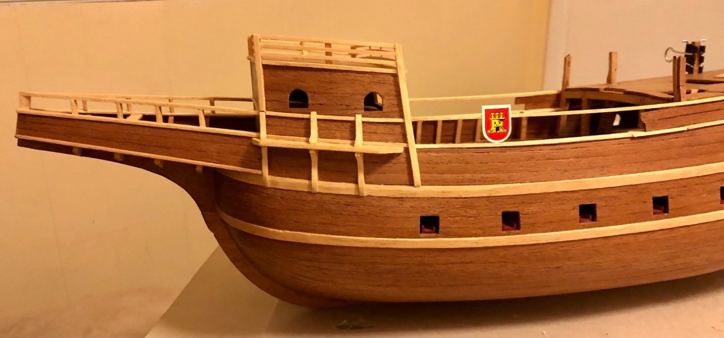
Thank you for the tip. Greatly appreciated!! Learned something new. Rounded kit provided 4x4 mm square stock into the round rod and niched the indentations according to the drawing. Of the few available built of this kit, lion figure head or other ornament was install on the head. The Spanish galleon of this time are basic utility vessel without elaborating decorations. I can’t find specific about those two head rods (please add, if you have info about them). I believe they are used like stag-horns to tie the bow of the ship to the dock. can’t help myself to do a bit of side by side comparison of my Mamoli roter lowe (un varnished, around the same built stage, 1/64): enjoy.😊😊 Roter has painted decorations and gallery balcony. Isabella (this the arbitrary name Billingboat give for this Spanish galleon) is approximately 50-75 years older than Roter (based on the masts configuration) Mamoli’s models are double planked kits. Although the two model are similar in size, roter weight about 3x as heavy (8-10 lbs) There are also common feel about the two ships. Roter has a curve head while Isabella has a straight and longer portional head to it’s hull length Roter’s fore mast is located within the forecastle while Isabella (this the arbitrary name Billingboat give for this ship) fore mast is in front of the forecastle. Isabella has 4 masts vs Roter’s 3 masts.


- 58 replies
-
- 6
-
-
- Spanish galleon
- Billing Boats
- (and 1 more)
-
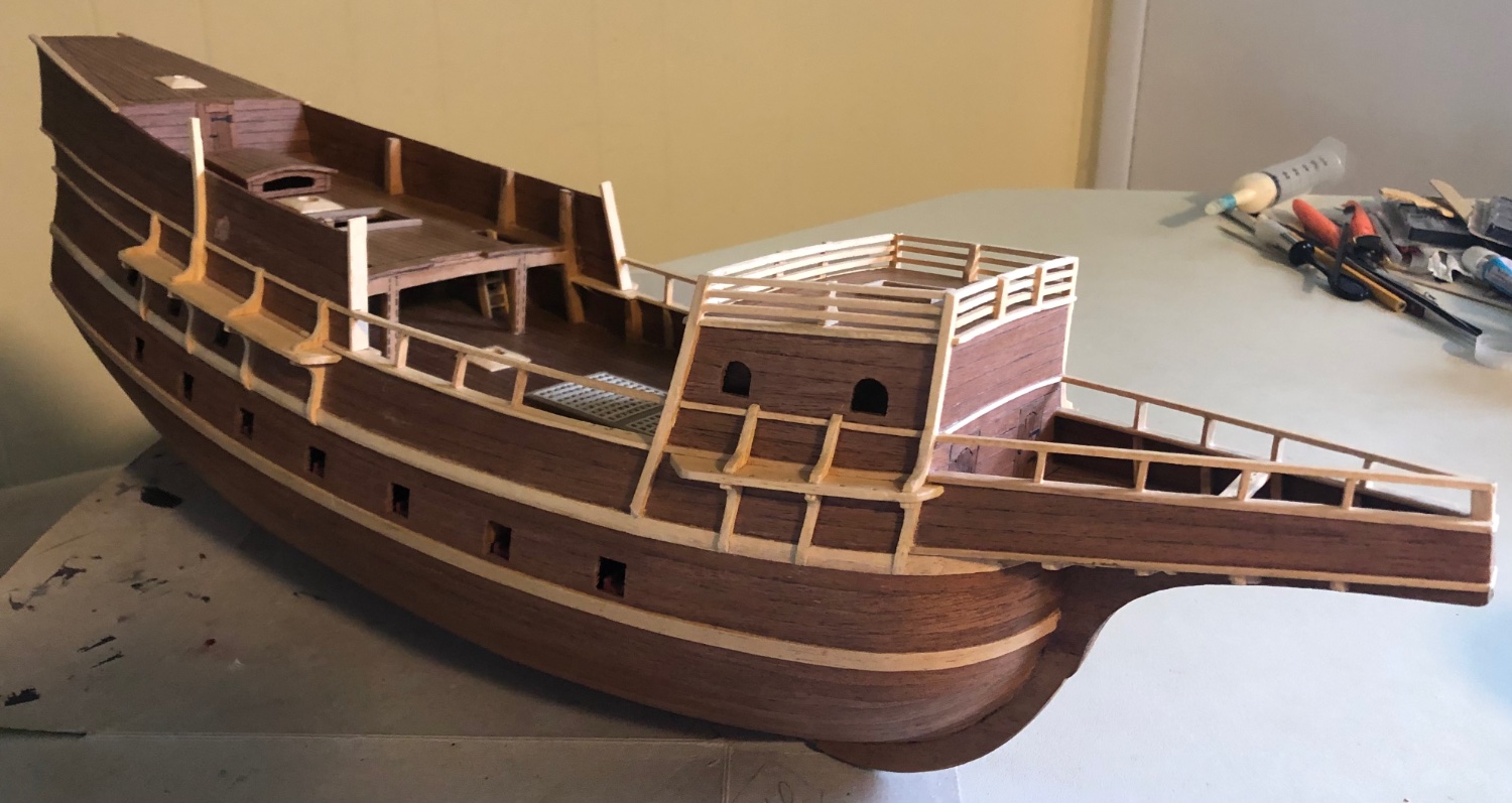
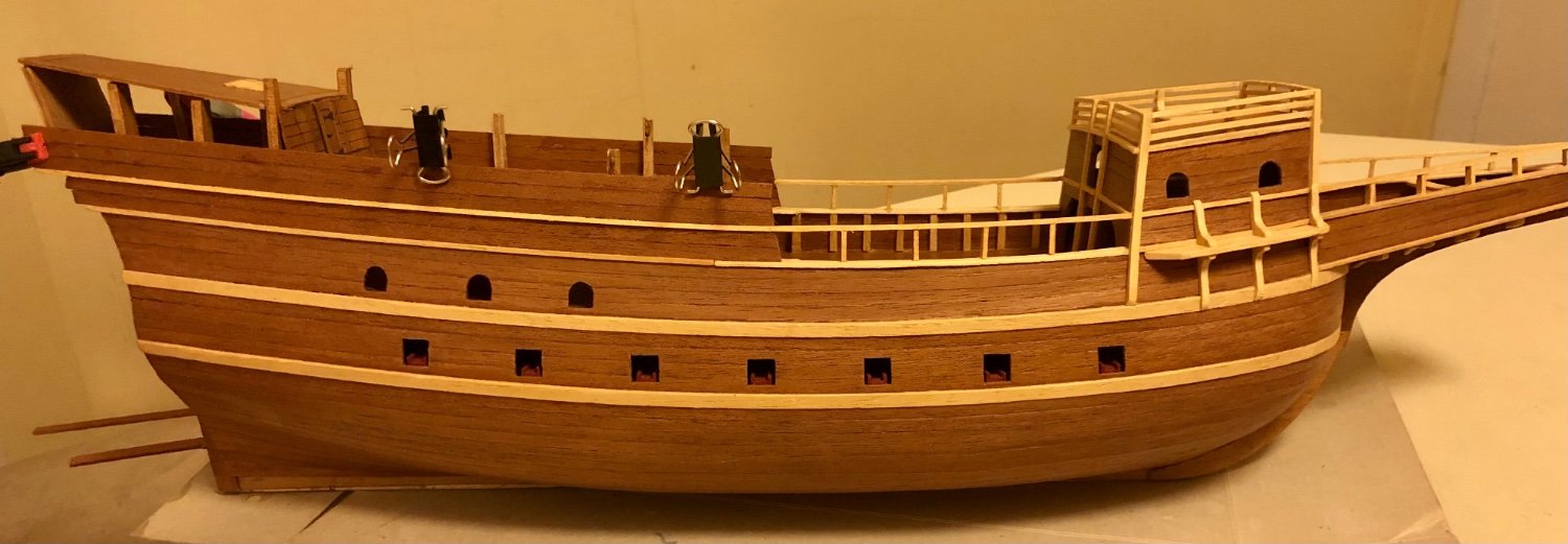
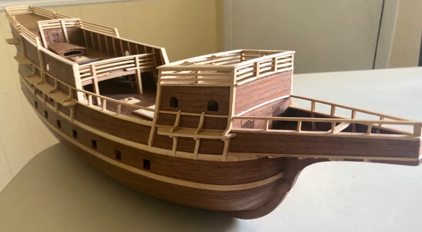
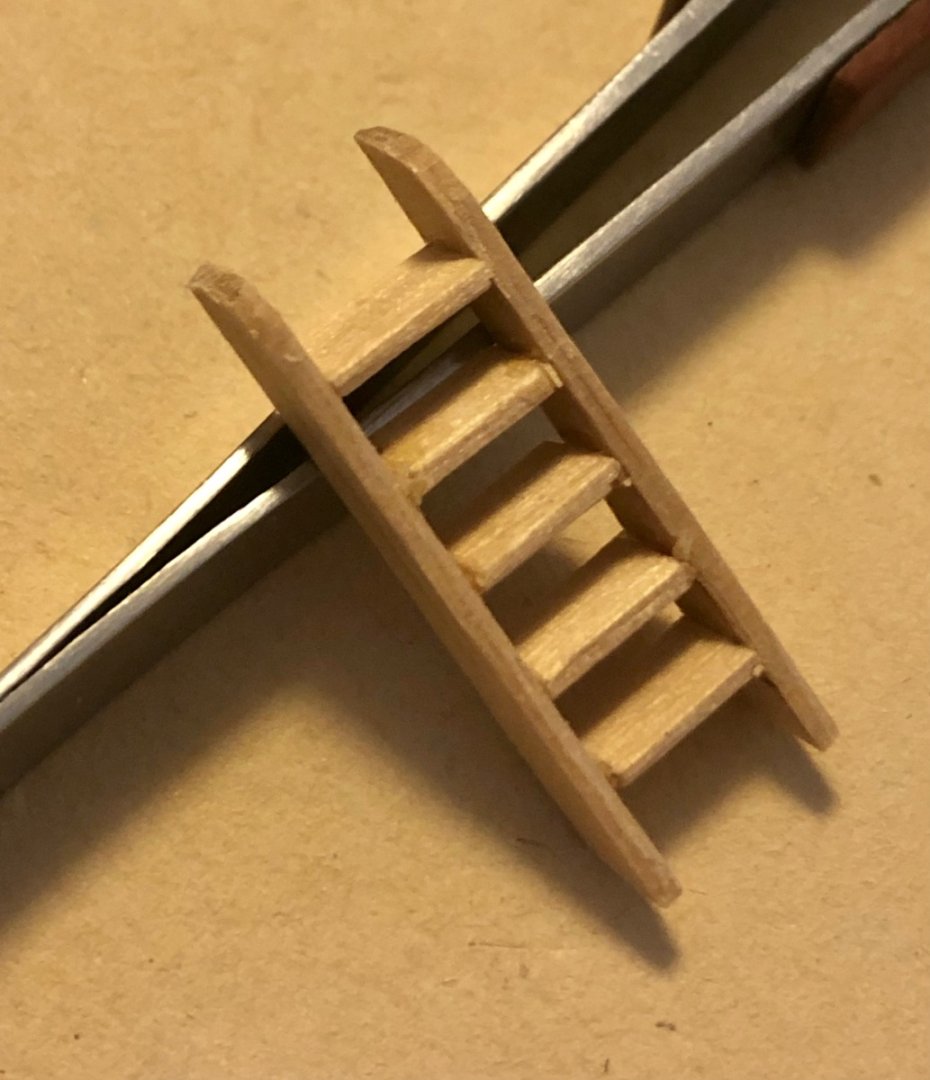
Added channels, rails & rail caps. The third & fourth channels installed ( this is a four masts galleon). Fitting the rail toward the stern. Adding the forecastle railing cap. excessive cap piece will be trimmed off after the glue dried. All hull rails installed. Rail cap for the quarter & poop deck still need to installed. The kit provided a single sheet for the stern gallery window. Decided to plank this section for better visual. Making the stern ladder from coffee stirrers. Completed ladder. Took about an hour to cut, trim and glue together. Overviews of the model after applying 2 coats of matt water based polyethylene. The main hull is almost completed at this point with only 4 rails to be added to the hull bulwark. I can’t seem to be able remove the below duplicate pictures no matter what,,,, oh well.


- 58 replies
-
- 8
-
-
-
- Spanish galleon
- Billing Boats
- (and 1 more)
-
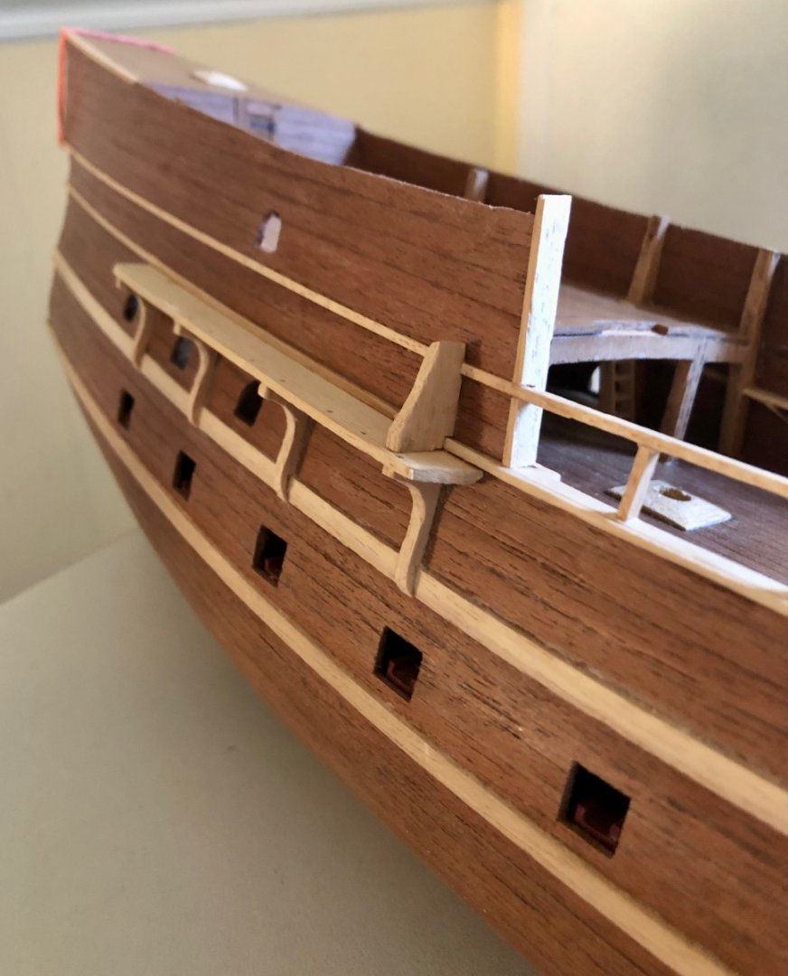
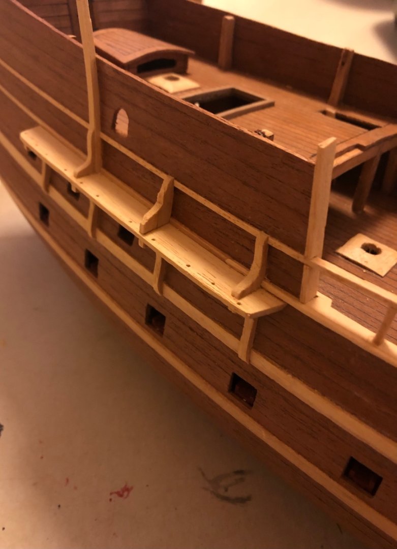
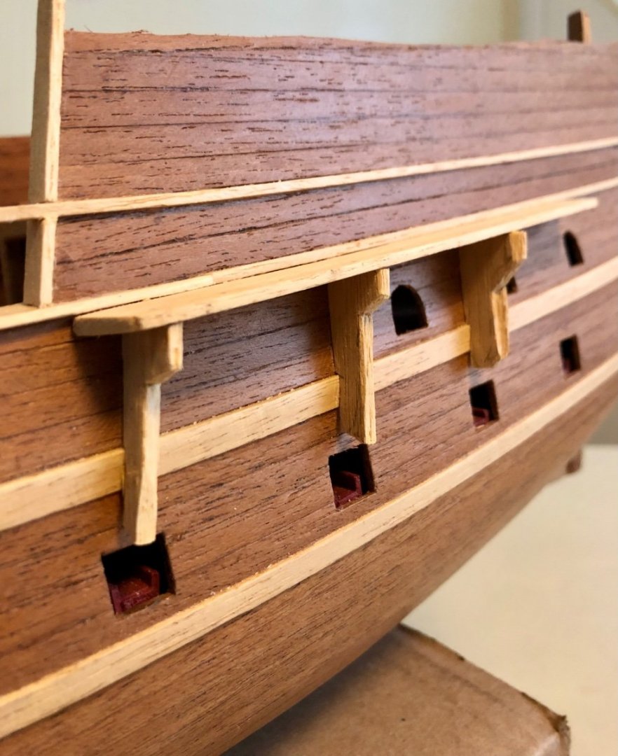
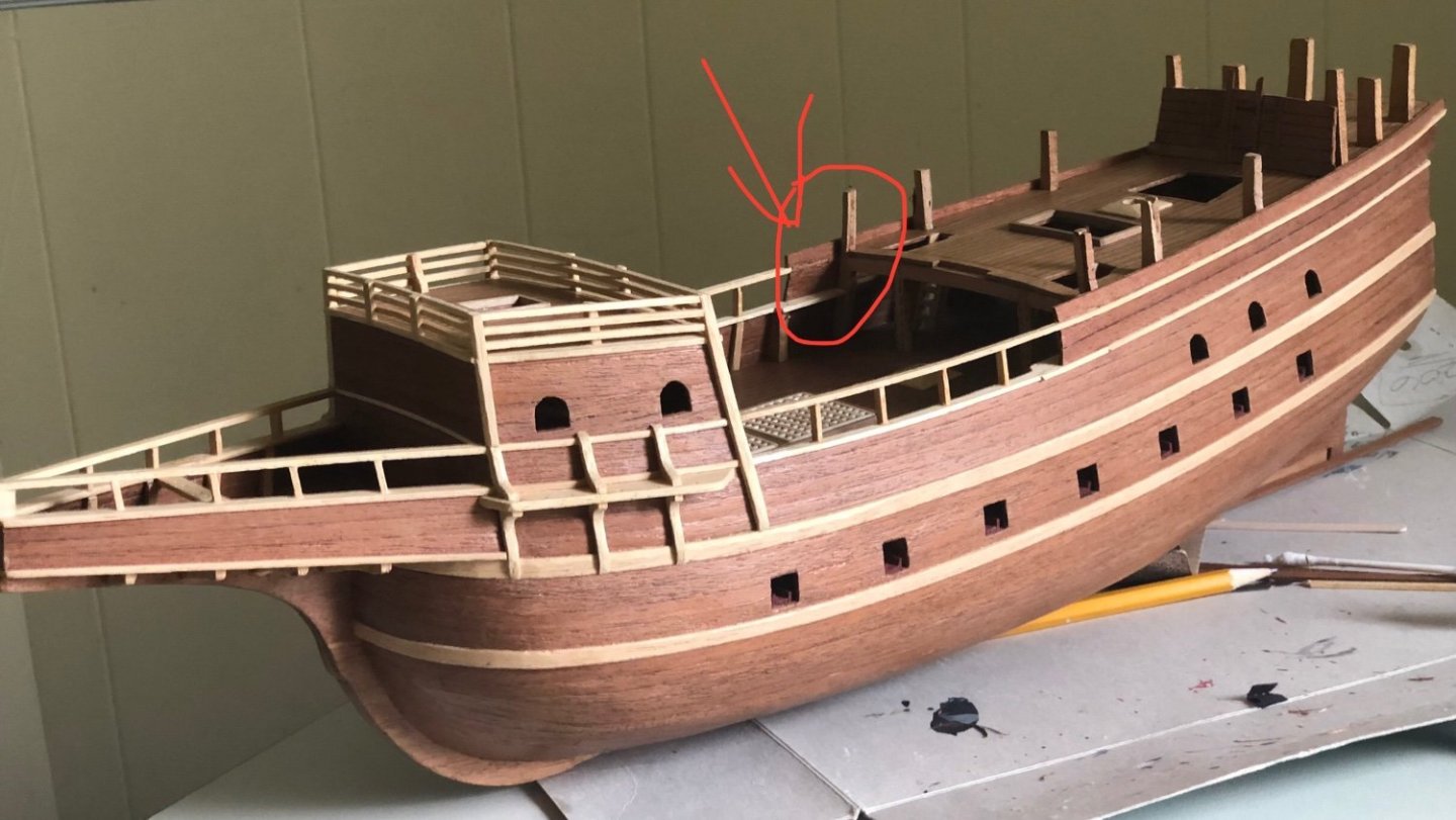
Starboard side main channel upper and lower knees completed. Took awhile as each knee is individually fitted and carved to shape. The first step is to ensure the rough knee is carved to the contour the hull’s lines. The third upper knees has an added hull stiffener stake behind it, so it is narrower compared to the other three knees. This hull stake extends higher than the quarter deck hull for supporting the upper railings (to be installed later). Installing the second rough knee cut out. Starboard side main channel knees shaped to the final dimension accordingly to the plan. Three quarter starboard view. Side view. correction update: after the initial upload and viewing the side view picture. I realized the the second upper knee vertical was slightly misaligned. It was corrected. before correction. After vertical angle correction.

- 58 replies
-
- 7
-
-
- Spanish galleon
- Billing Boats
- (and 1 more)
-
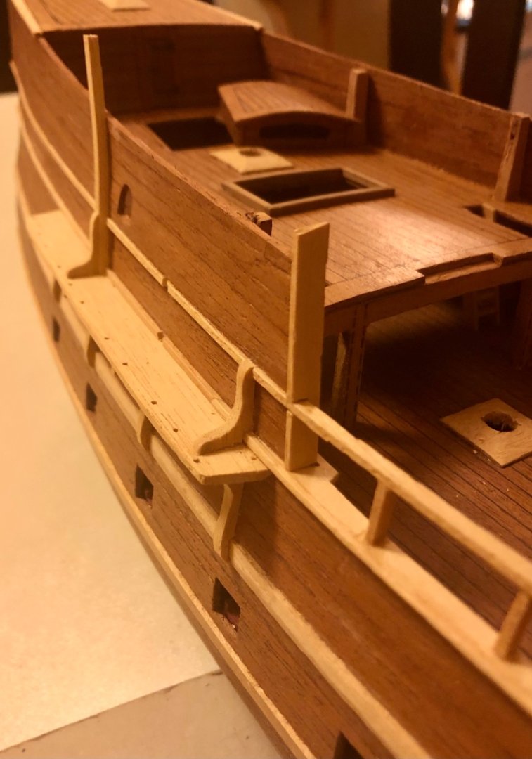
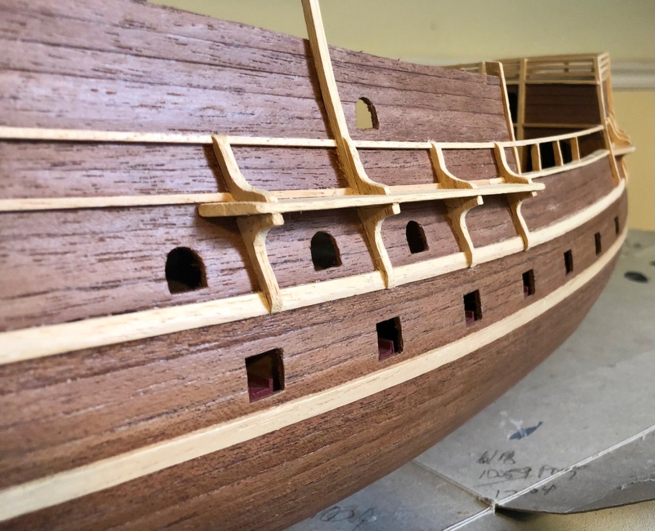
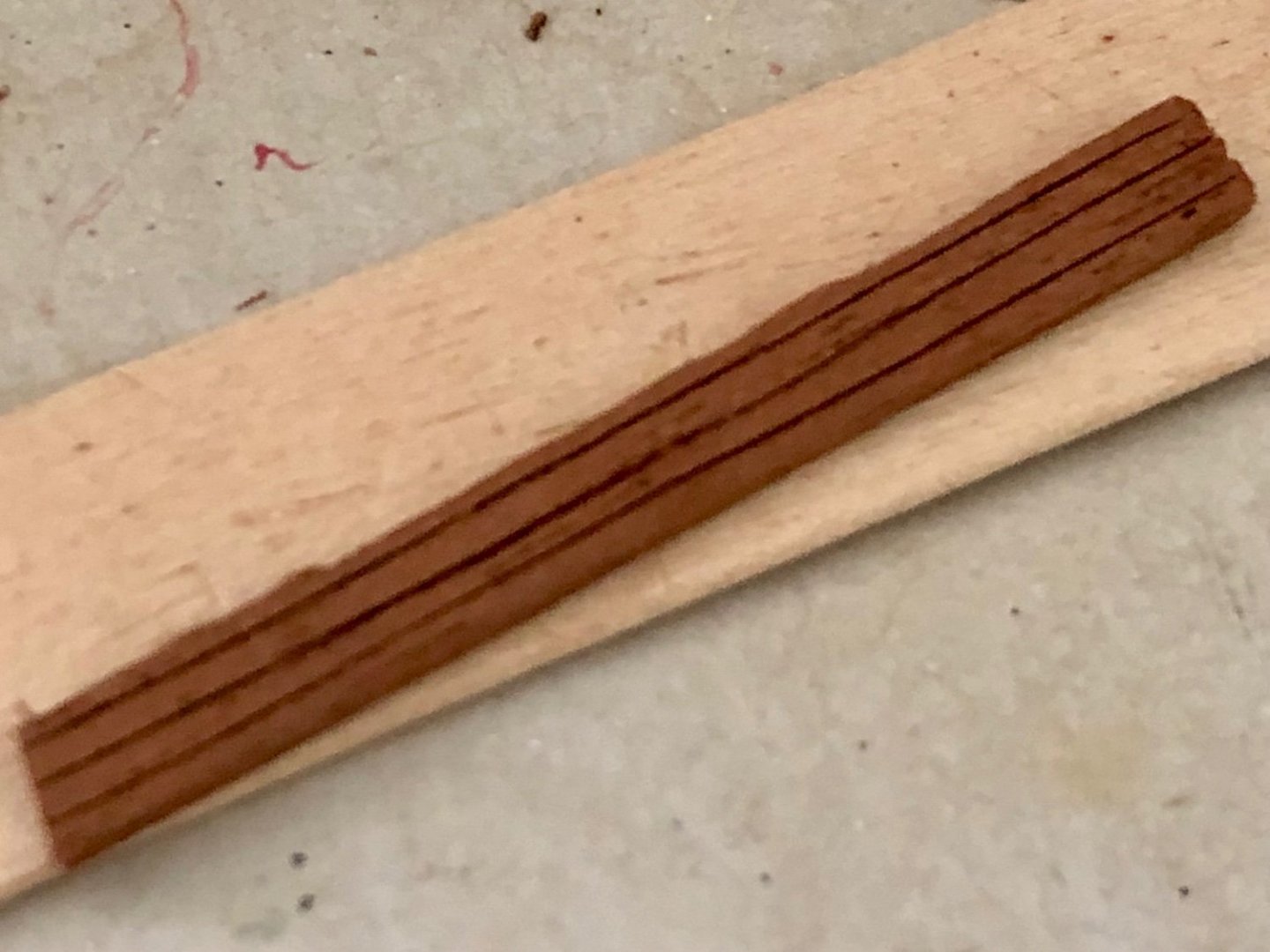
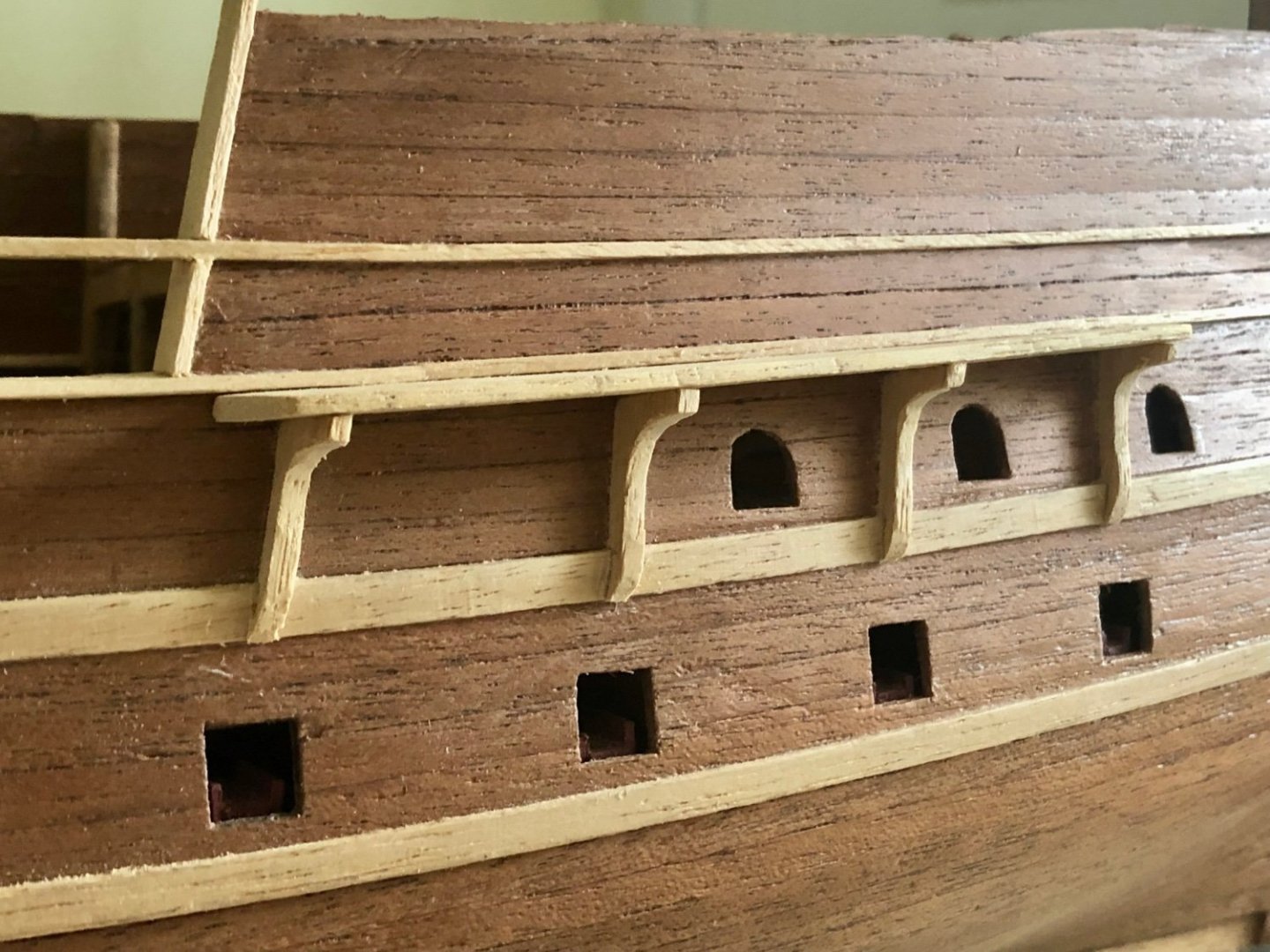
The curve part of the stern was planked in. Due to the extreme curvature and trying to keep the plank as the same size as others presented a challenge. The solution was to make number of parallel cuts (1/2 the plank thickness) from the back side of the plank strip. Those cuts allows the plank to be spread out into the curvature as needed. The main mast channel was installed according to the drawing. Top view of the installed main mast channel. The quarter deck hull edge was cap off with a 2x7 mm end piece. A notch was cut into the strip to accommodate for the upper shield rail. Quarter deck hull edge piece installed. Rough cut outs for the lower knees were attached to the main master channel. It was pointless trying to cut accordingly to the printed outline from the component board (which are identically inform), as the hull shape is constantly changing and unique. The rough cut out just need to be larger and longer than what the final knee shape needs to be. The lower knees were shaped individually to the final dimension. A side view of the main mast channel & shaped lower knees.


- 58 replies
-
- 9
-
-
- Spanish galleon
- Billing Boats
- (and 1 more)
-
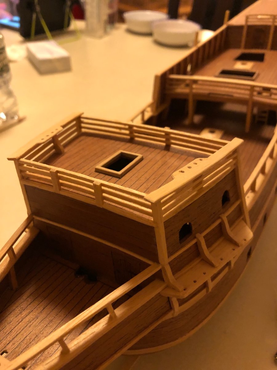
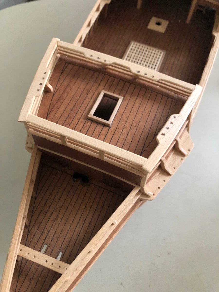
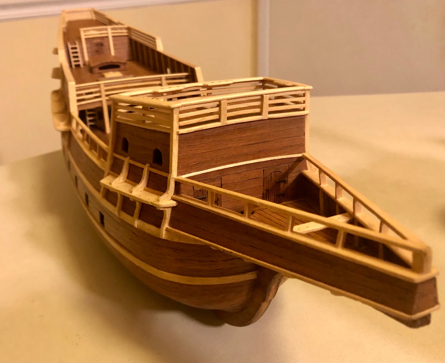
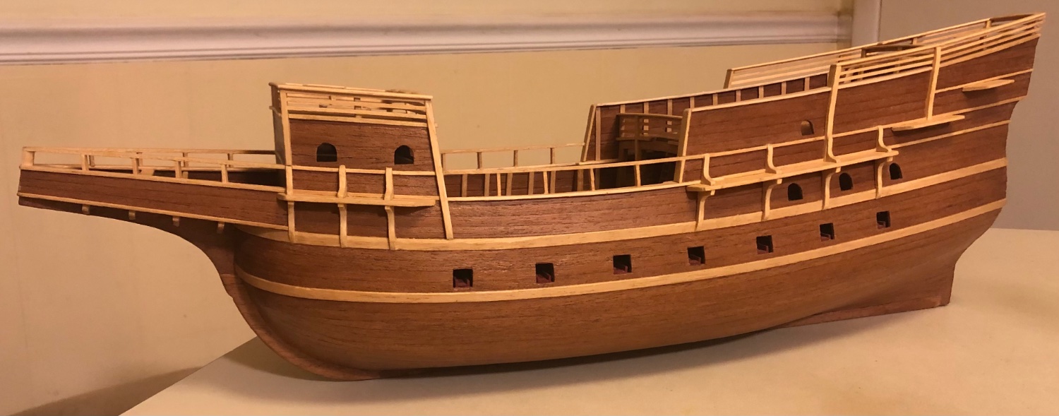
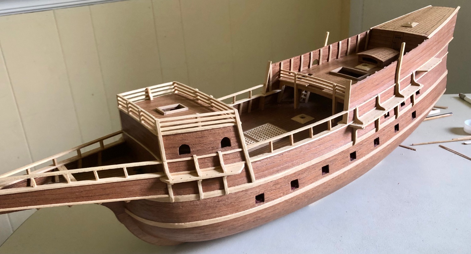
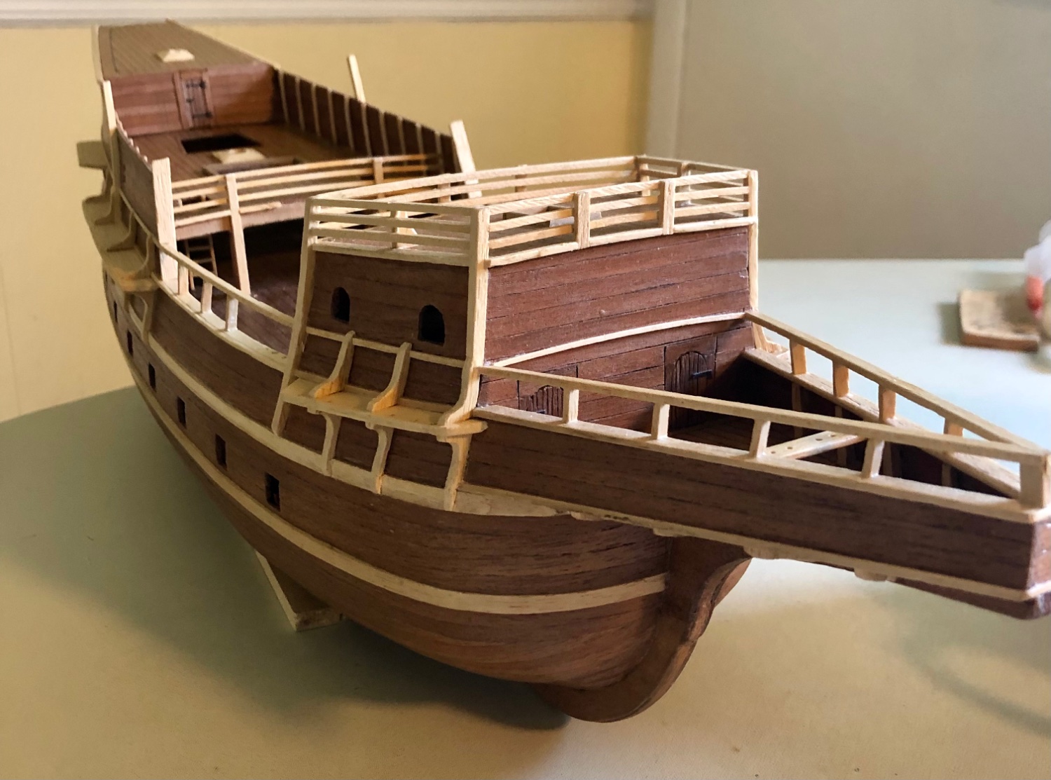
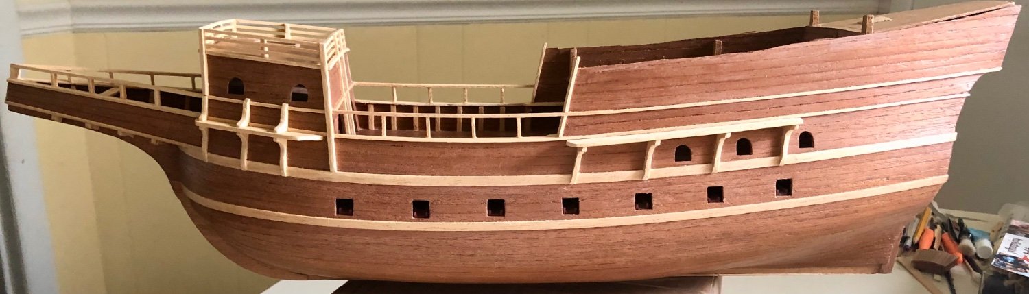
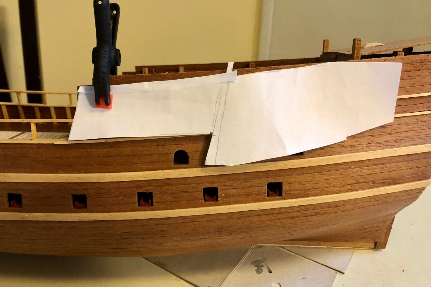
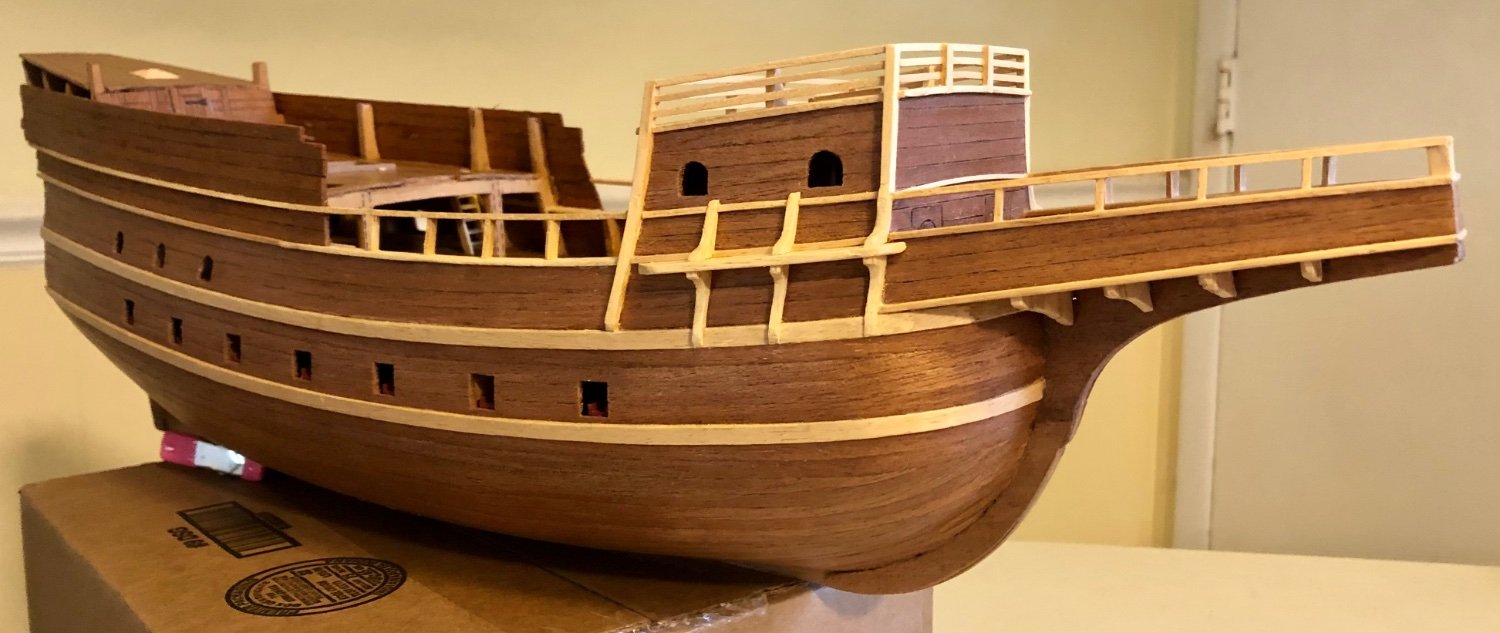
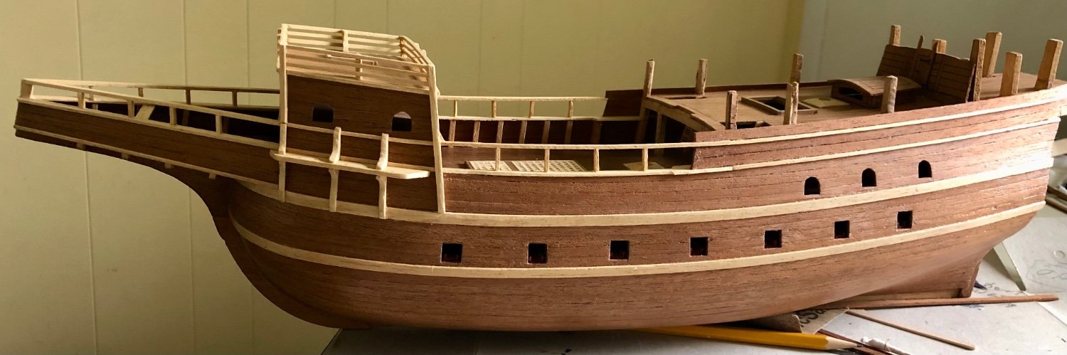
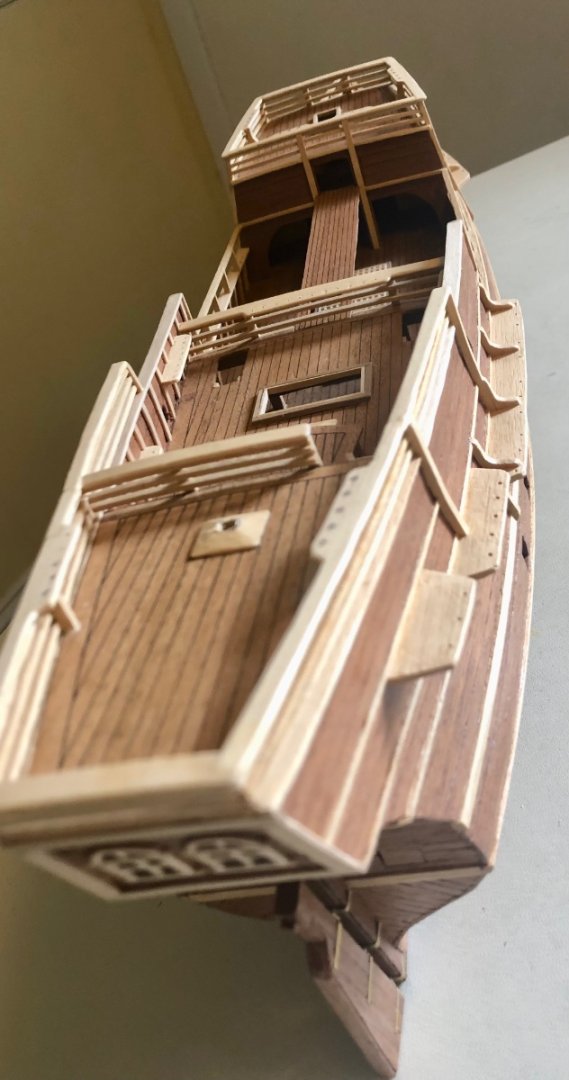
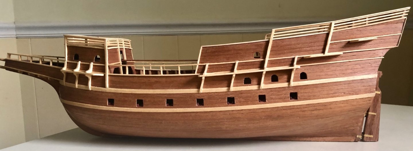
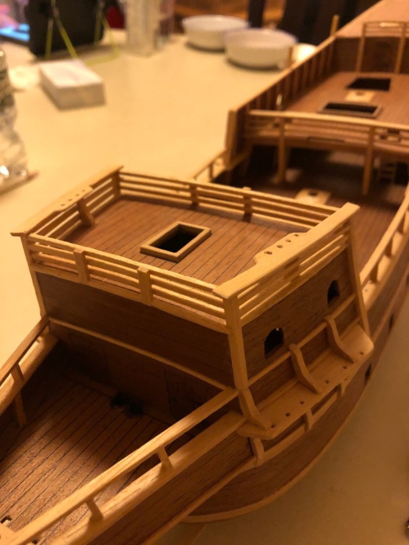
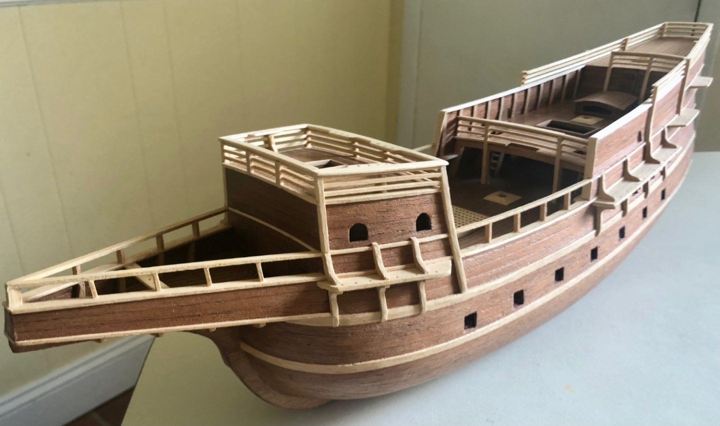
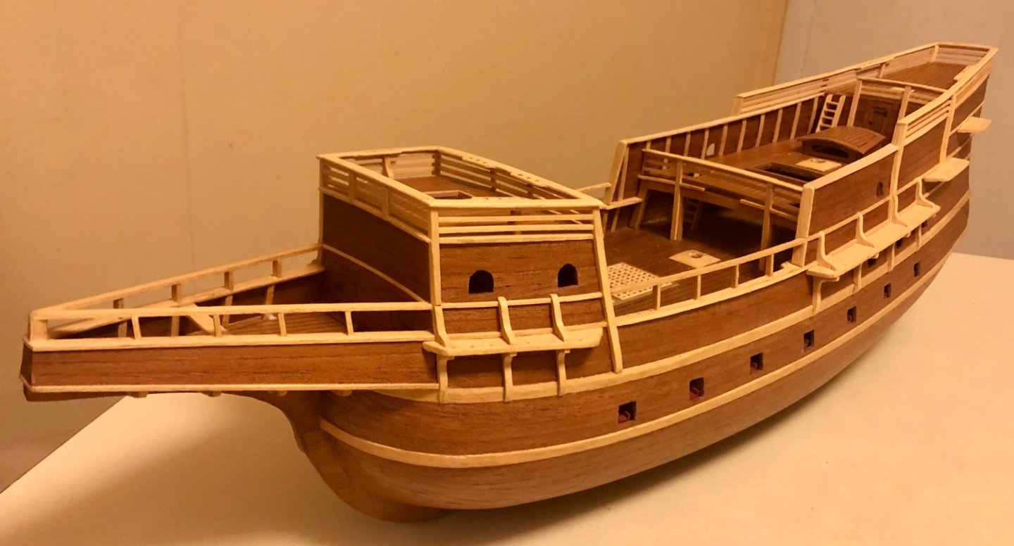
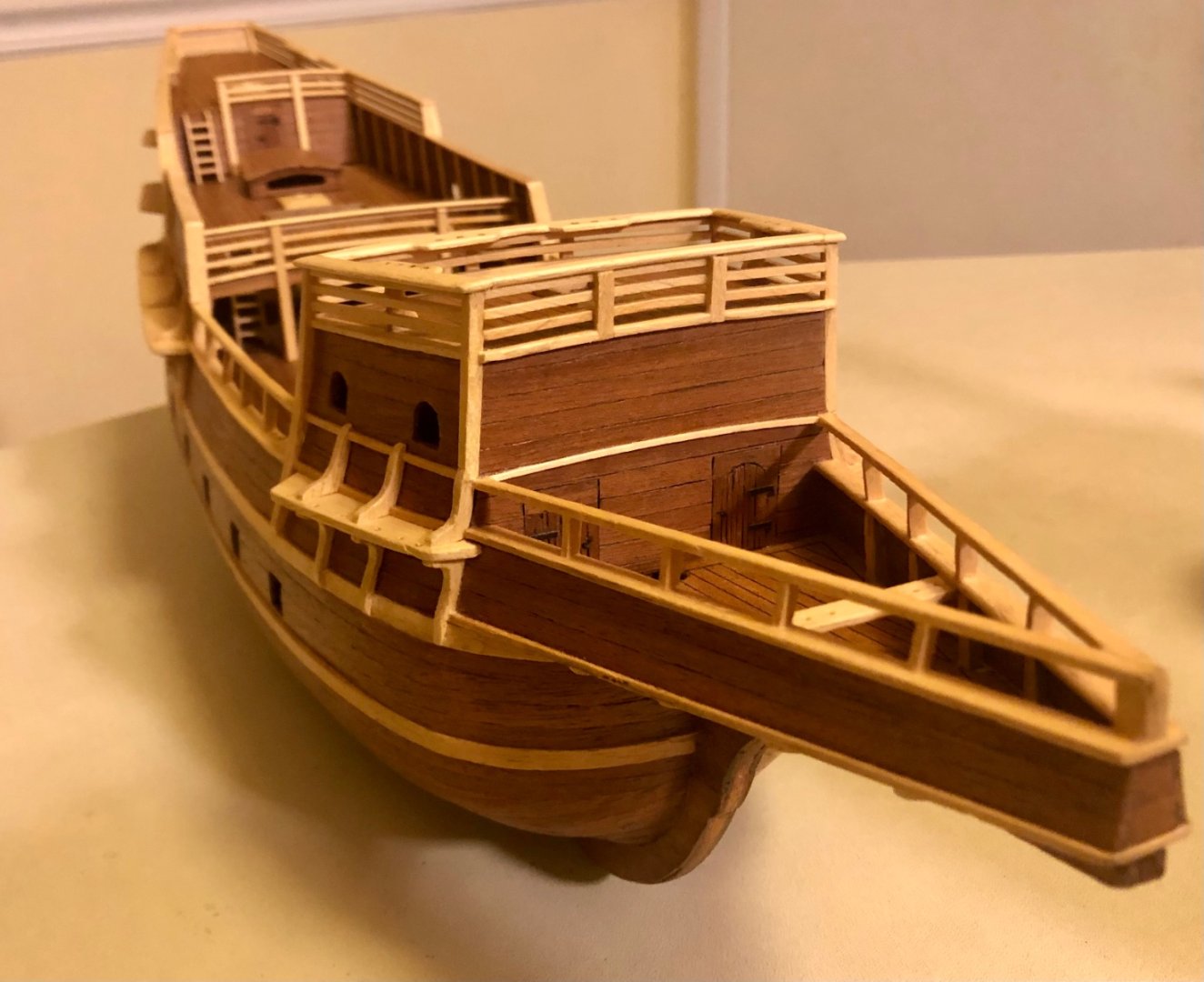
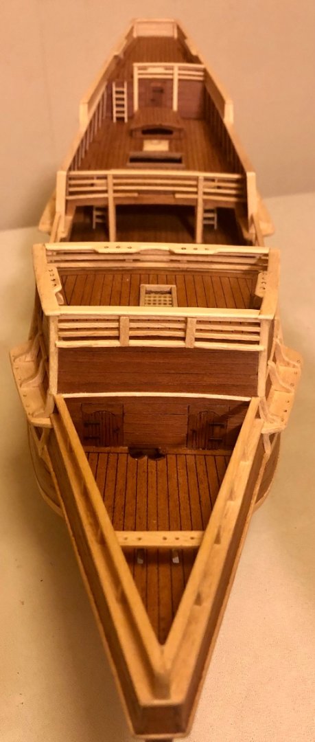
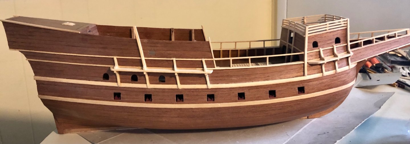
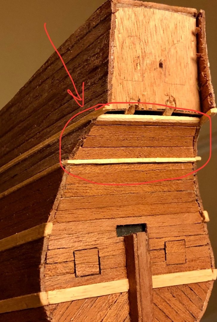
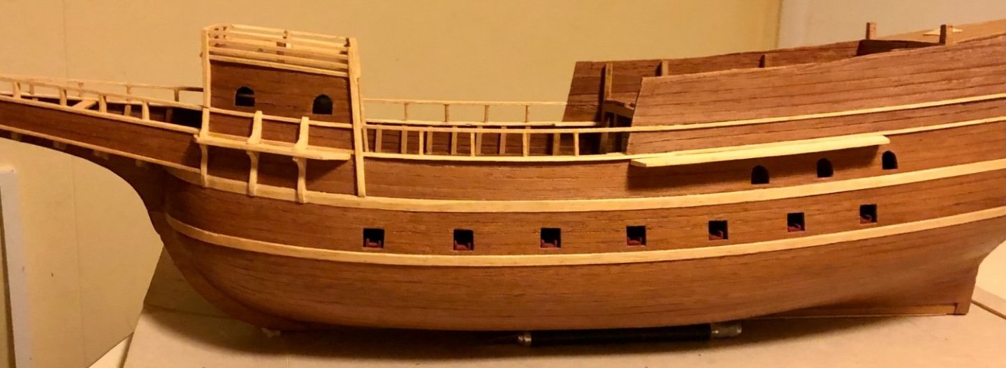
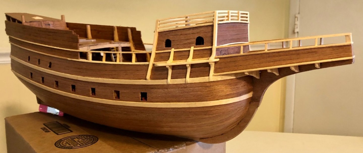
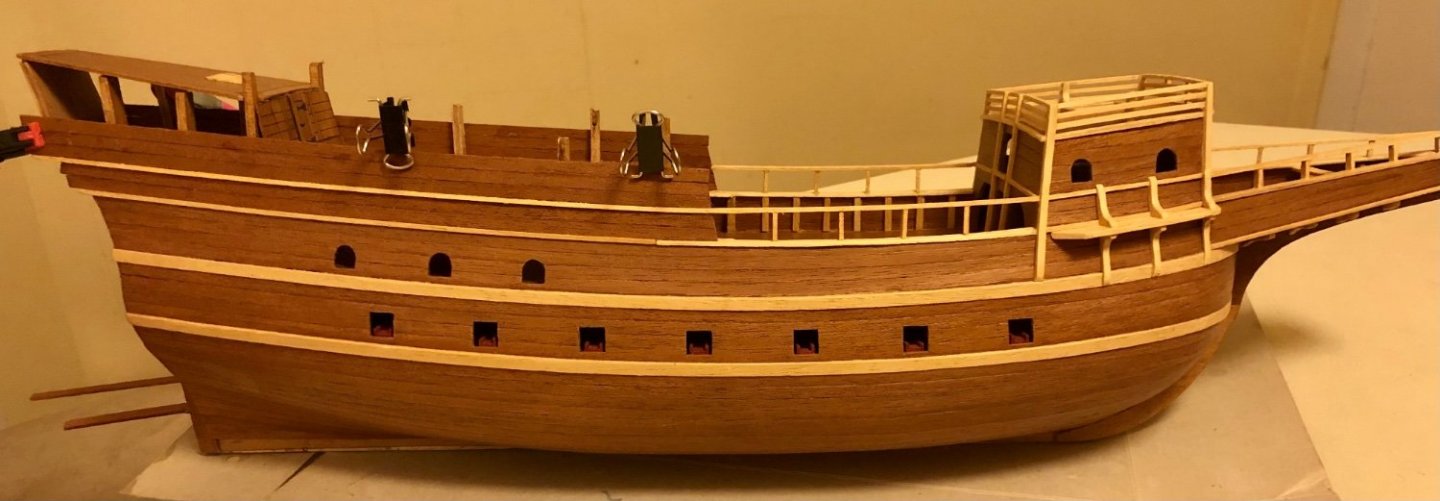
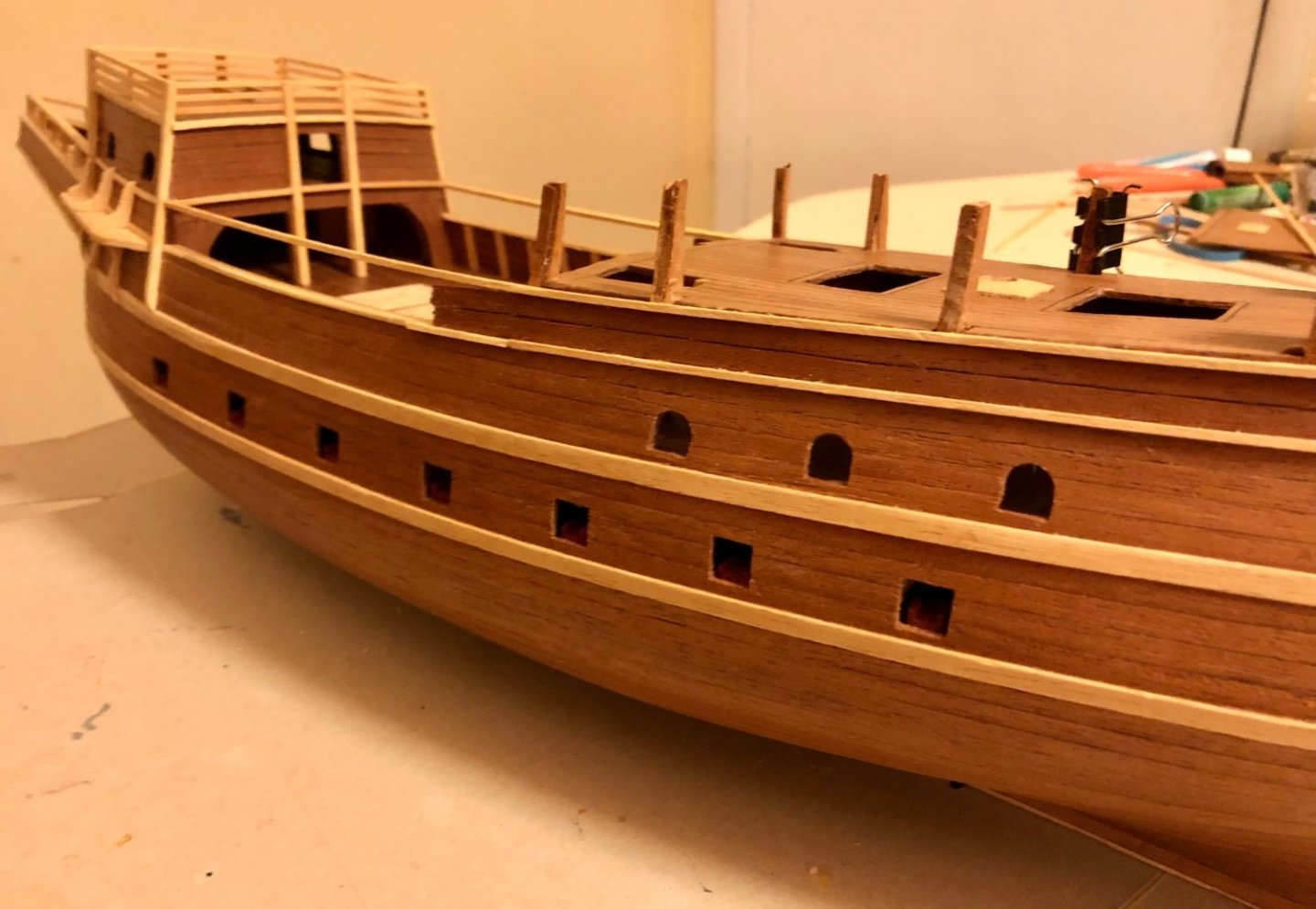
The stern half of the upper hull went up quickly after installing the poop deck & the stern cabinet front & back piece. The fast pace was possible because the area is less curvaceous. Bow view toward the poop deck. With most of the quarter deck hull planked, the familiar high hull silhouette of the galleon is now apparent. Hull curvature carried through from the bow to stern can be clearly appreciated from this angle. Ps. The main deck hand rail (slightly lighter color) will likely to be cut back flush to the hull and a new trim piece made out of the same wood used for other hull trim will be fitted in its place. The wood color difference is just too much for me to ignore. A paper template traced out from construction drawing is used to gauge how much of the quarter deck hull need to be trimmed off. stay tuned…


- 58 replies
-
- 5
-
-
- Spanish galleon
- Billing Boats
- (and 1 more)
-
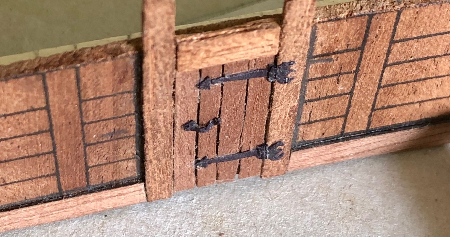
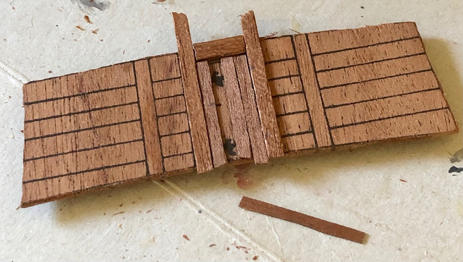
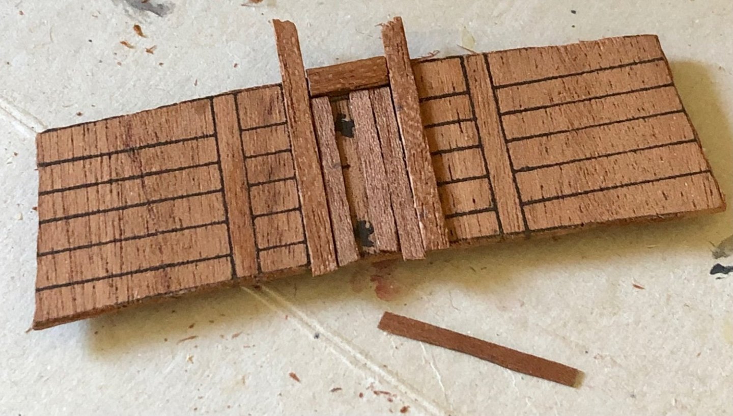
Billingboats’ older kit lacks detail depths (printed flat outline for details). Adding scrap wood strips to build out the door frame, door and side planking. New door hingers & handle were added (the printed image was covered by the door planks). They were cut out using heavy black construction paper and glued in place. Glued into placed. The horizontal planking will be added as the hull planking is being installed (to ensure there wouldn’t be gaps between the two). Three overview pictures of the model as build to date: Will update when more progresses are made. Stay tuned…


- 58 replies
-
- 7
-
-
-
- Spanish galleon
- Billing Boats
- (and 1 more)
-
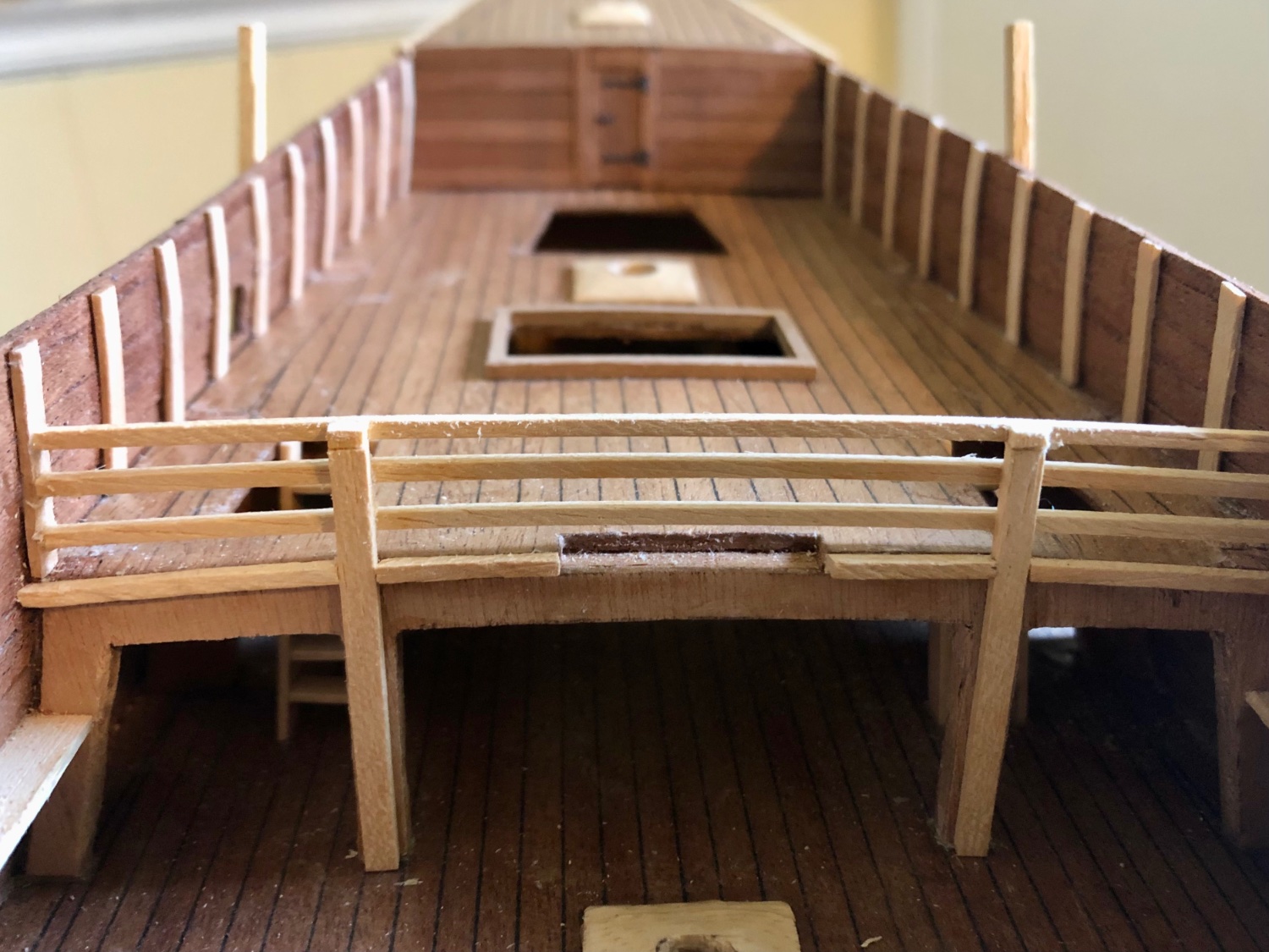
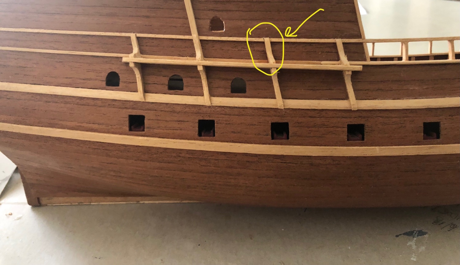
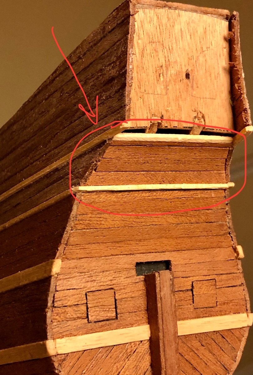
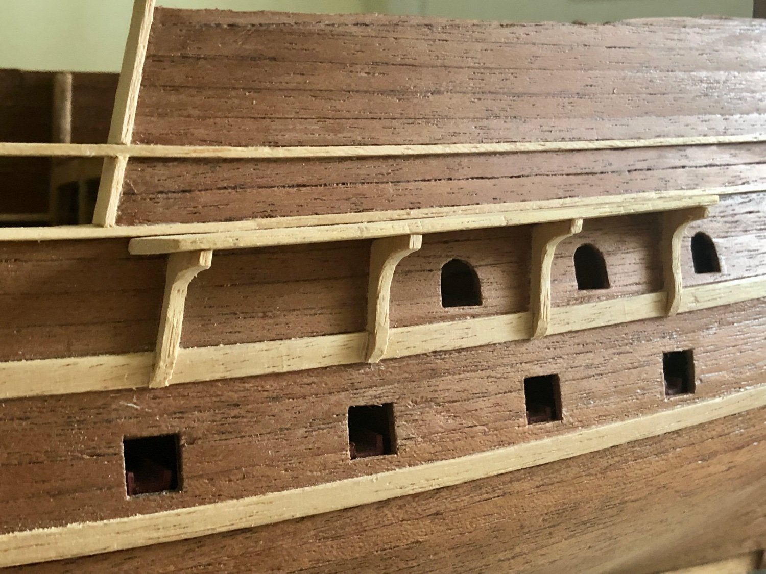
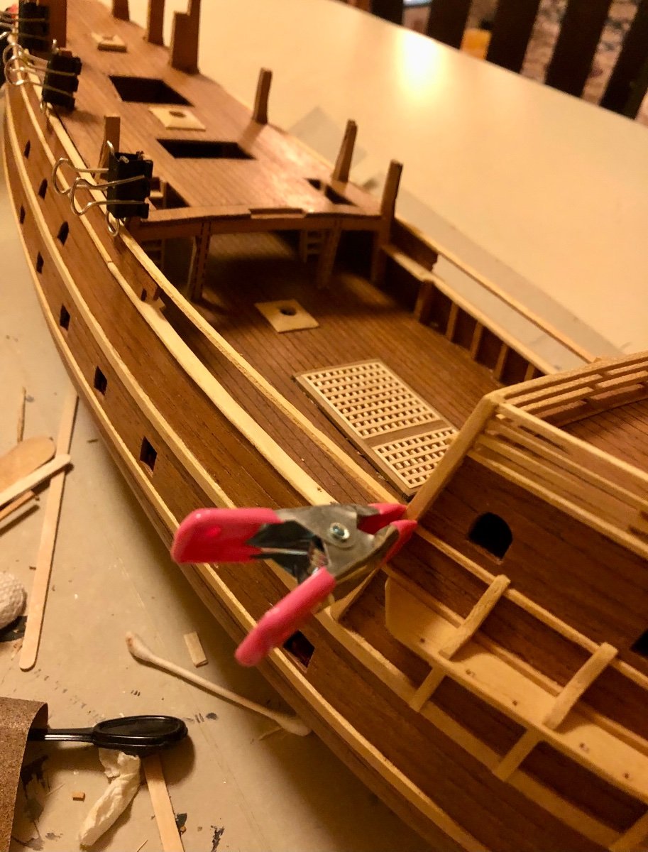
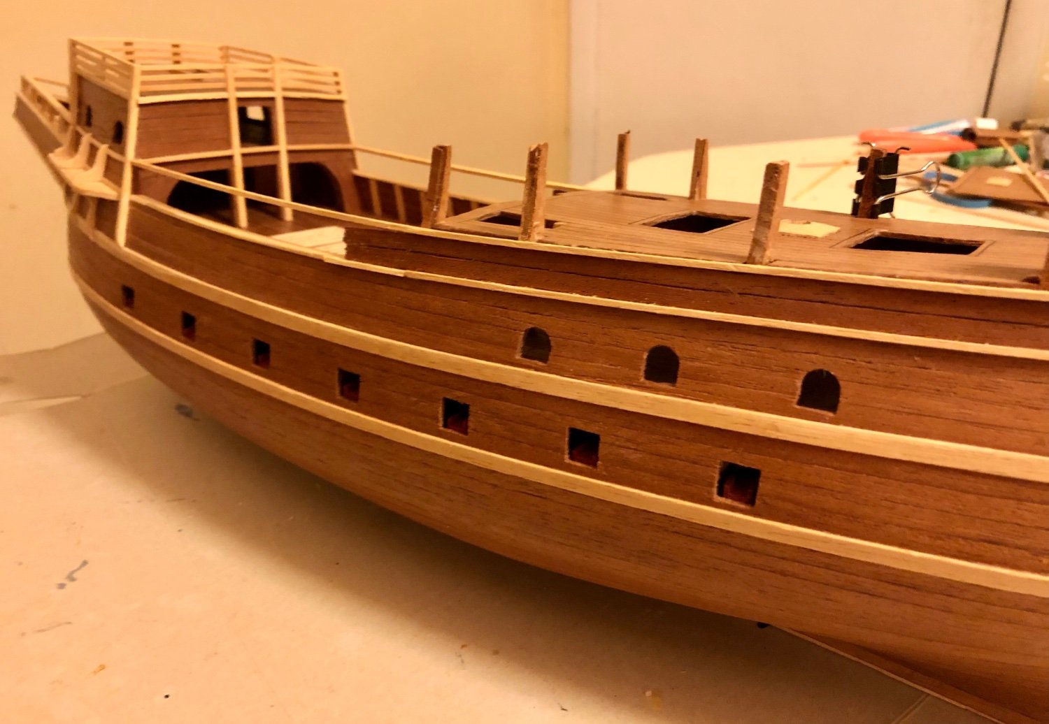
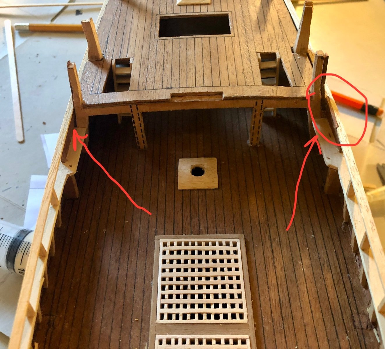
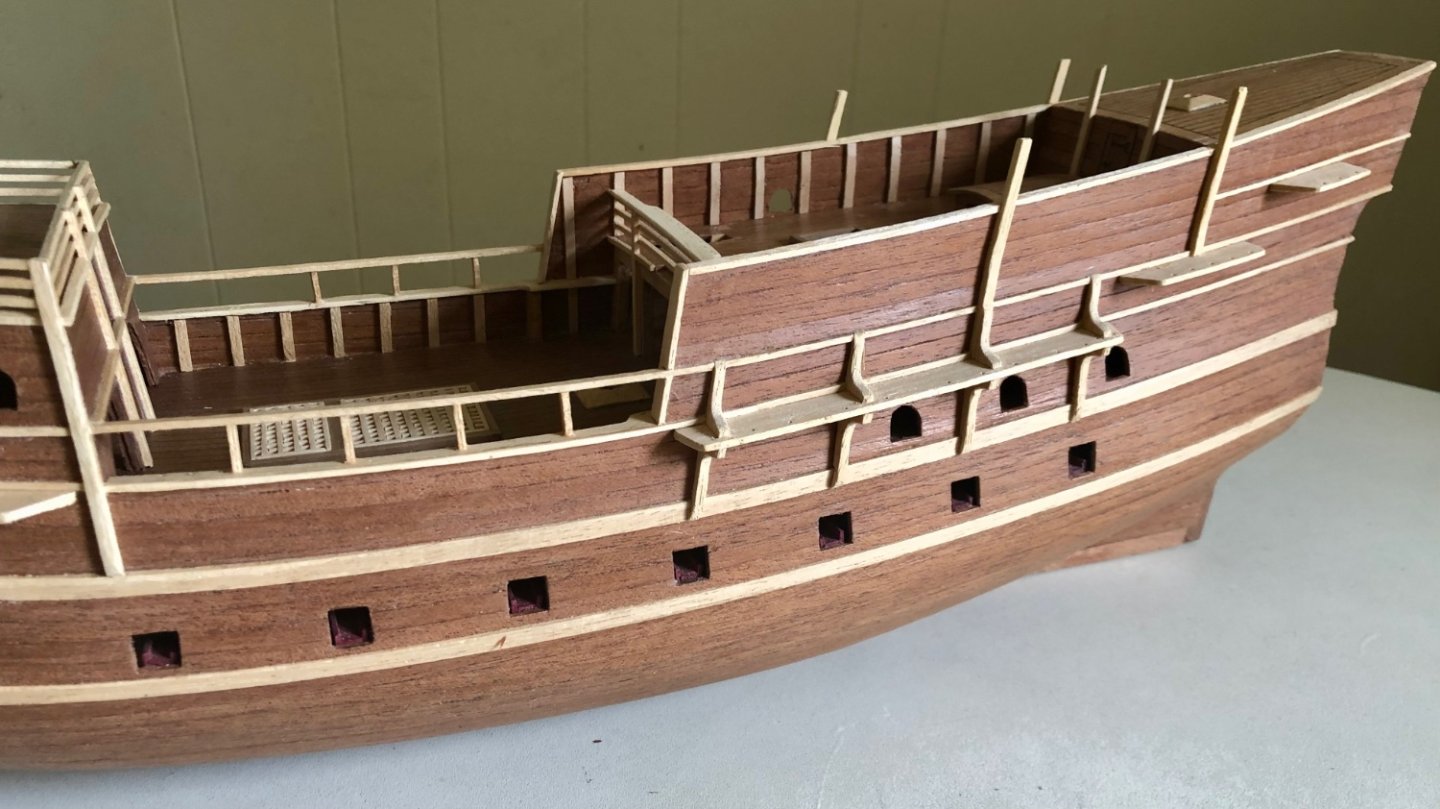
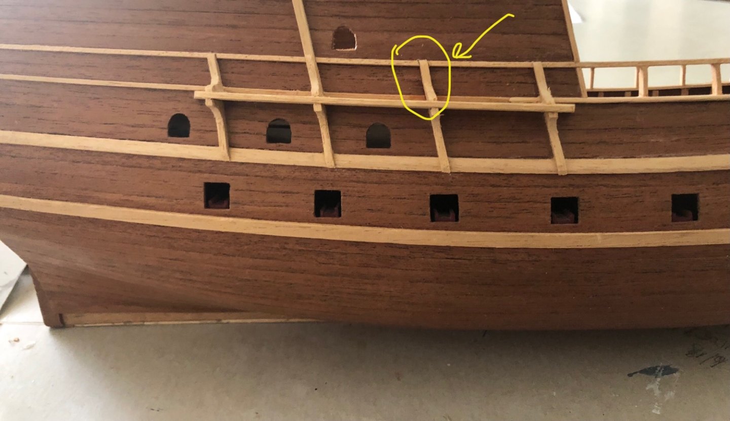
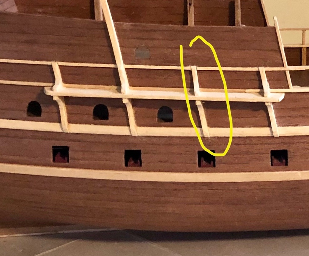
Thanks Baker for your confirmation. Updated 6/7/2922. Installing the upper rail for the shields to lay against. This rail would also serve as the drapes support for the anti-boarding net (back then, naval engagement is about get close to the enemy’s ship and board the ship to fight it out & take the ship as the prize. Unlike later on, to sink the enemy ship as far away as possible with canon fires). This rail runs all the way to the stern (this why the components on the main deck need to installed beforehand. Access will be harder) using one of shield to check for rail spacing. The vertical rail supports installations turned out to be a nightmare (as they tend to pull on the upper rail as the glue dries. This distorted the rail to linear instead of the original curve parallel to the hull). I ended up gluing the vertical supports to the mid ship deck rail. After they are firmly dried, then glue the top rail one at a time until each is solidly dried first. That did the trick. Since this is a single plank model. The rail (a horizontal light wood streak running in parallel against the darker hull bulwark) will be visible. A portion of rail that would visible is craved out(see right side arrow) and replaced w the same hull wooden strip (mahogany). The hull bulwark looked as it should after the craved out replacement (no light color rail strip visible).

- 58 replies
-
- 6
-
-
- Spanish galleon
- Billing Boats
- (and 1 more)
-
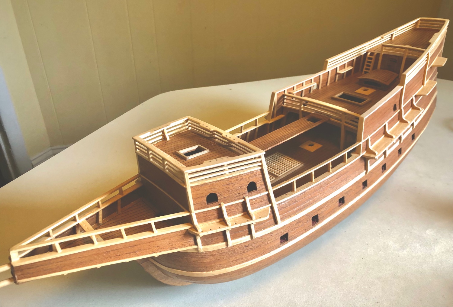
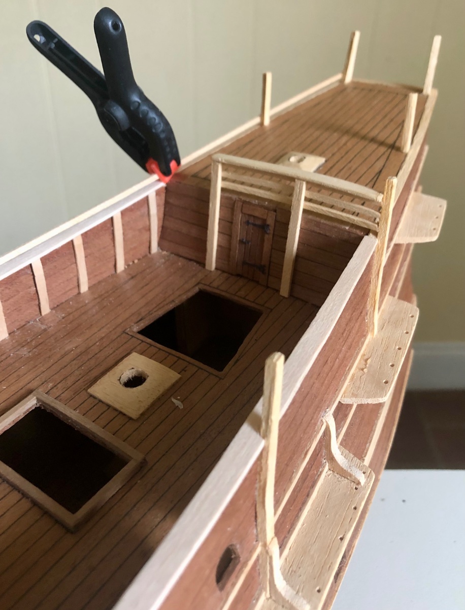
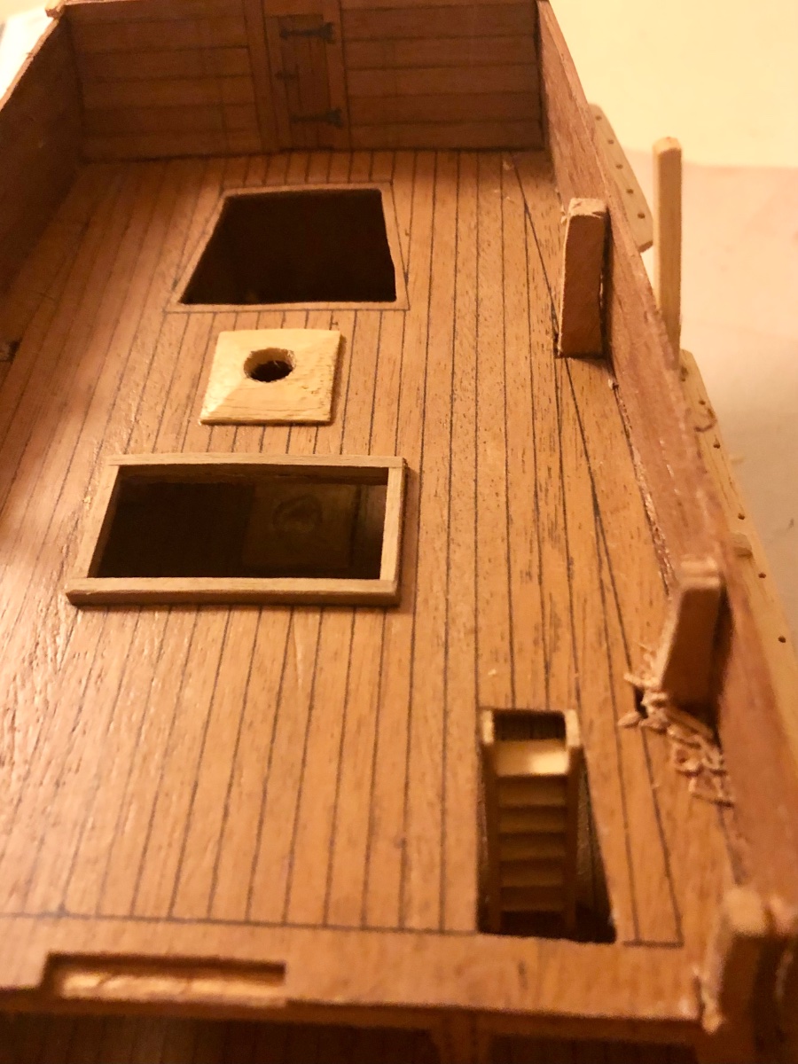
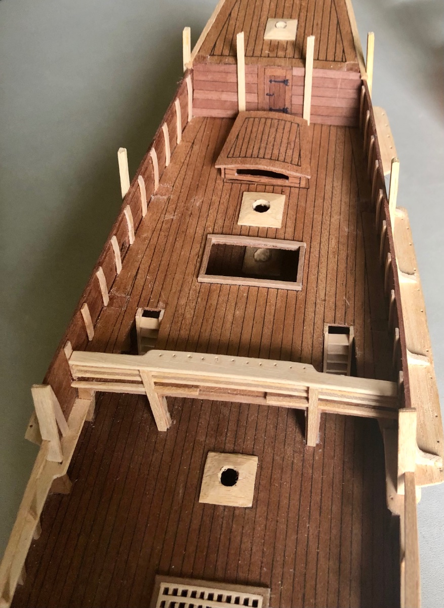
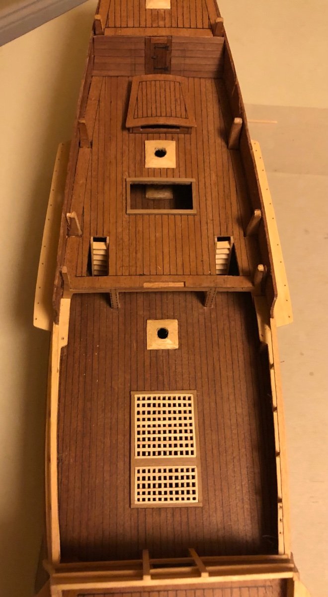
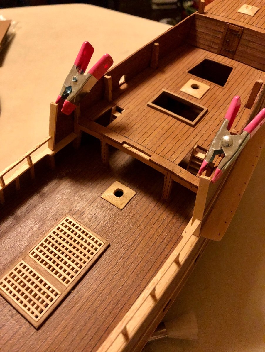
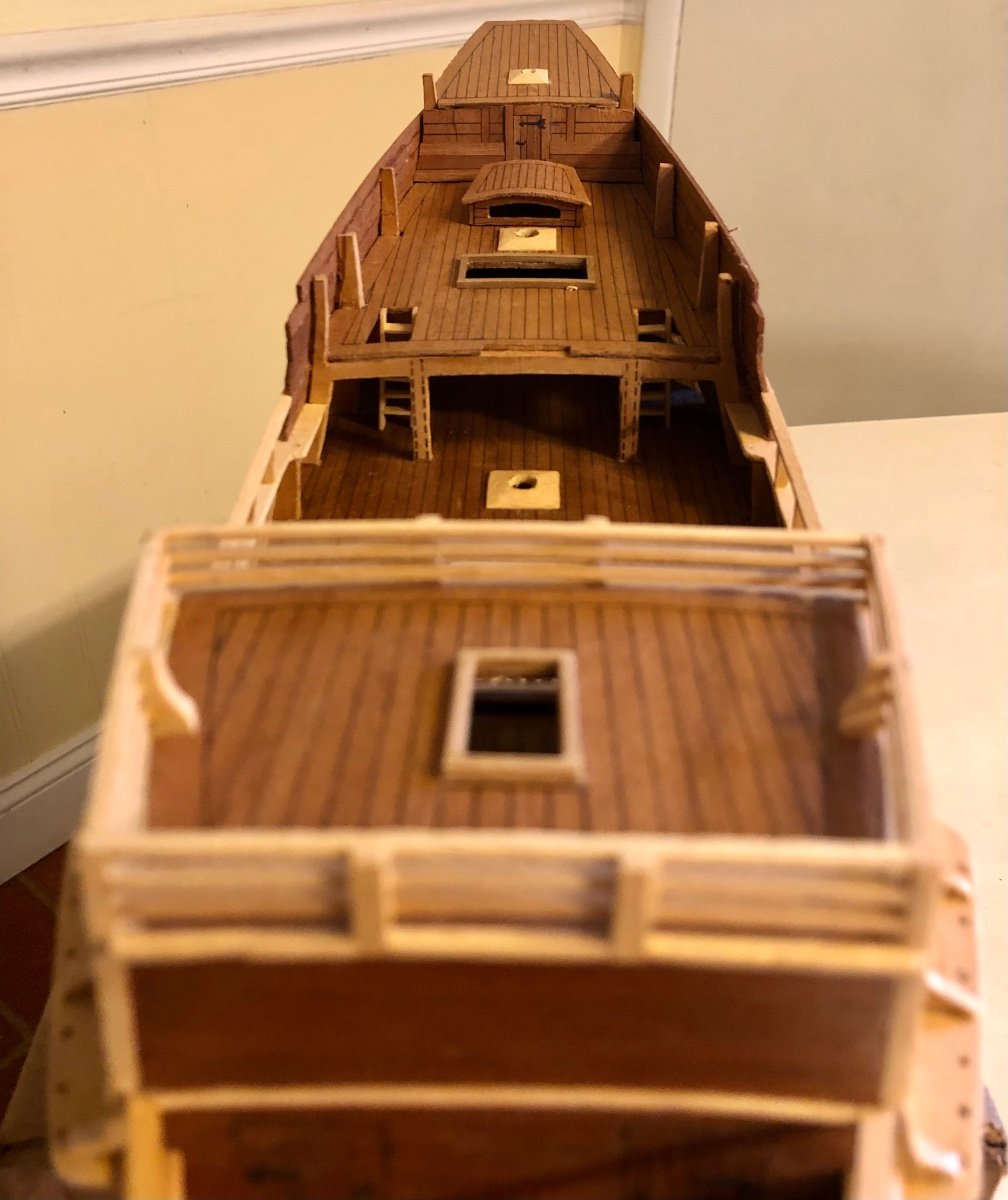
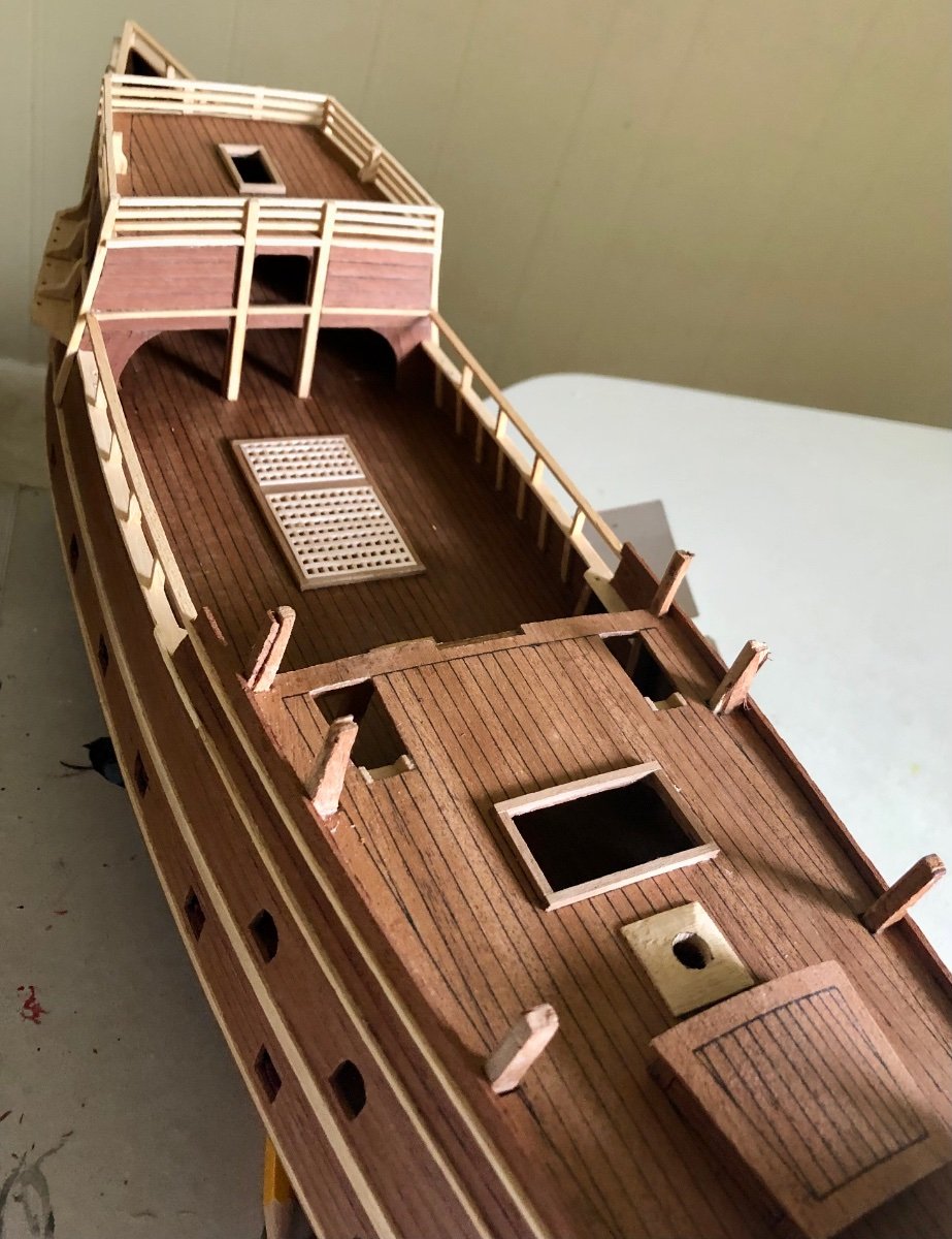
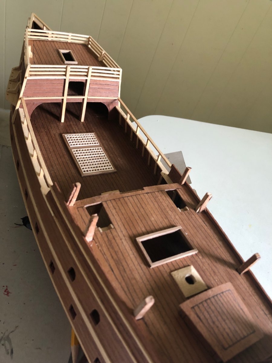
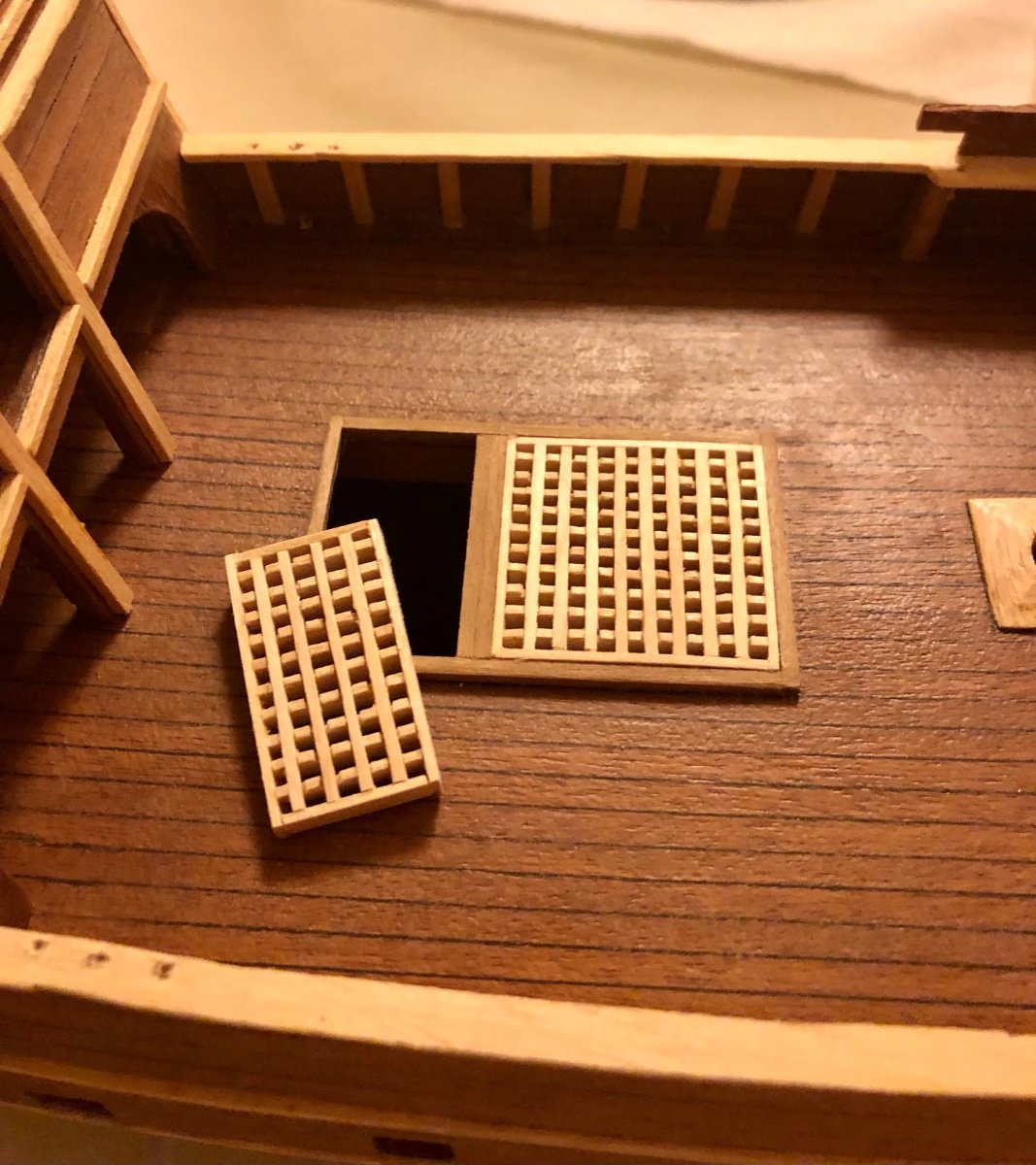
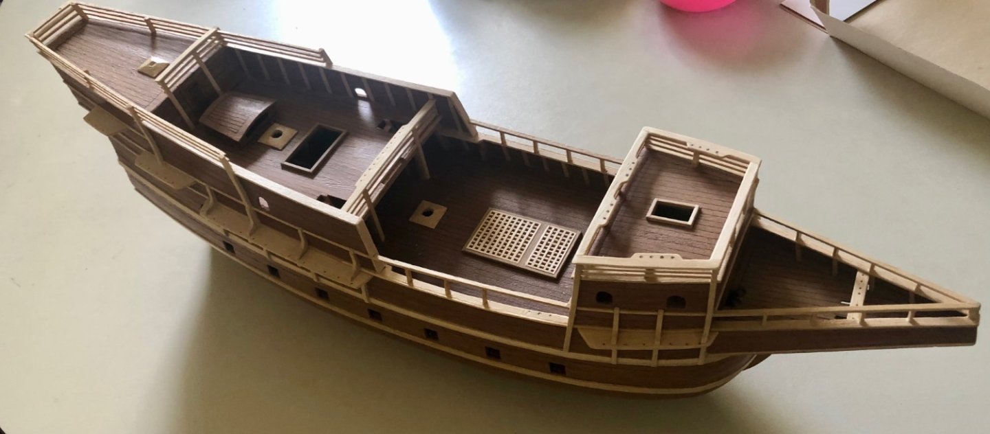
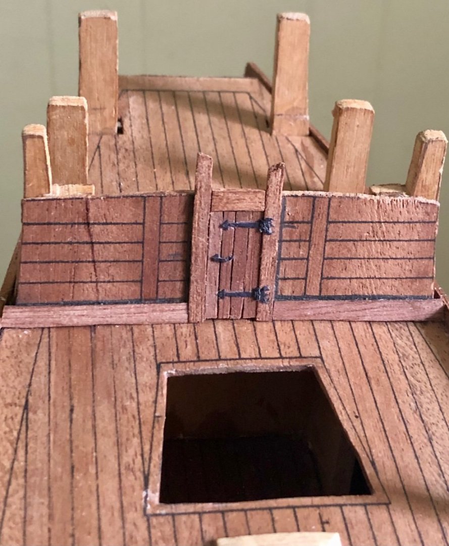
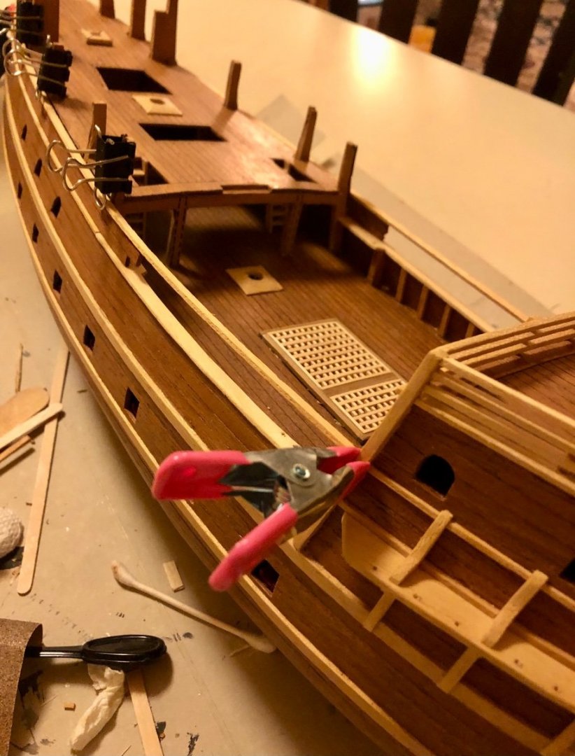
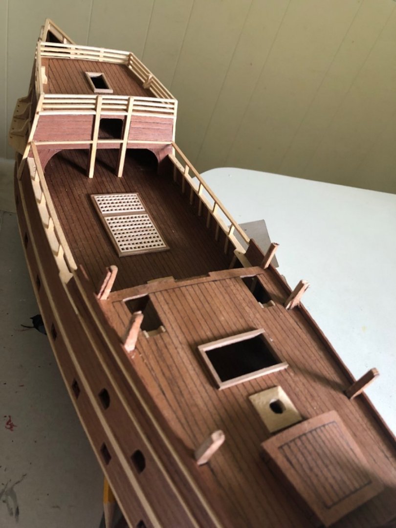
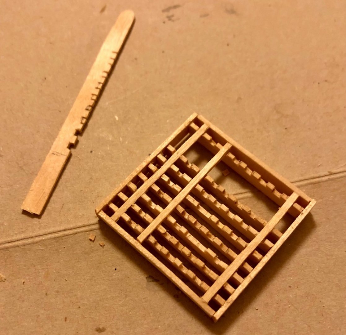
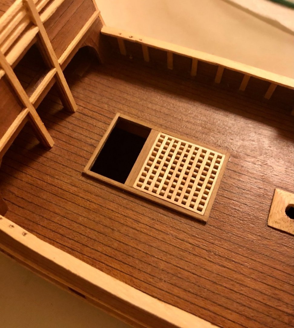
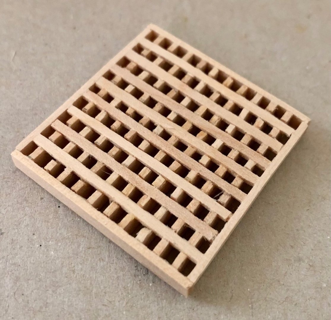
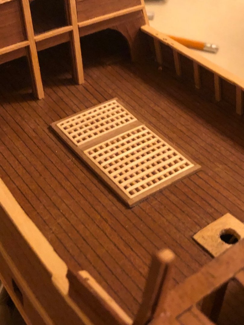
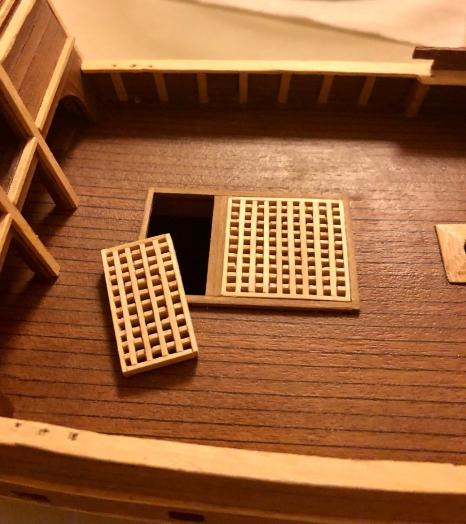
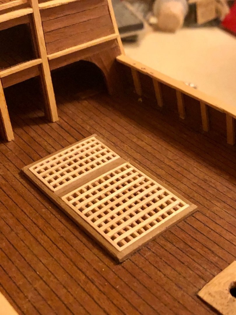
Thanks LCdr David for your kind words. I liked the Billing boats’ Mayflower model( it has a very classic hull profile) and will be look forward to see your build log. After reviewing the construction drawing, it became obvious the main deck hatch need to be completed before aft hull planking can resume (due to the horizontal trim (2 x3 mm stock running from the end of forecastle all the way to the hull stern. This is the upper support beam for installing the shields over the mid ship area). Once this trim piece is installed, any work in the main deck will be more difficult afterward. I don’t have the Billingboats’ fitting set for this kit. But based on what i can find online, there isn’t much included - plastic hatch covers, turned wooden crow nest, plastic dead eyes and blocks,,,etc). I decided to build the hatch grill from scratch using one of my favorite and cheapest wood - wooden coffee stirrers. it took awhile to construct the grill from the coffee stirrers (Material costs next to nothing), but it looks better than the Billingboats’ one piece flat plastic grill. What do you think ? The mid ship hatch area is quite large. I decided to divide the area into two sections; a main hatch and a smaller forward hatch. Spare walnut stakes (2 x2 mm) from previous project were used to frame out the hatch framing. The forward grill is constructed. Keep in mind most of those deck grills are removable in real life and should have an all around framing surrounding it (a lot of the build i seem omits this - frameless). Both grill hatches installed. .
- 58 replies
-
- 6
-
-
- Spanish galleon
- Billing Boats
- (and 1 more)