
Draque
-
Posts
26 -
Joined
-
Last visited


-
 Prowler901 reacted to a post in a topic:
San Francisco II Galleon by Draque - Artesania Latina
Prowler901 reacted to a post in a topic:
San Francisco II Galleon by Draque - Artesania Latina
-
BLACK VIKING reacted to a post in a topic:
San Francisco II Galleon by Draque - Artesania Latina
-
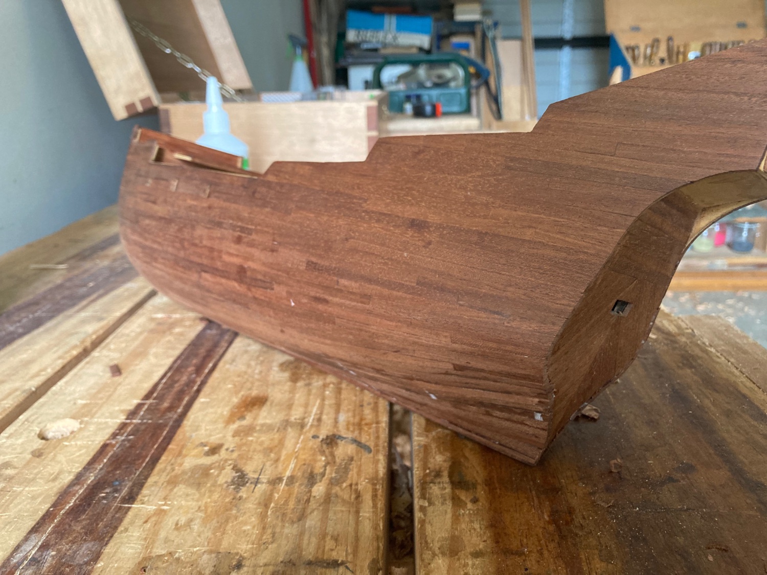
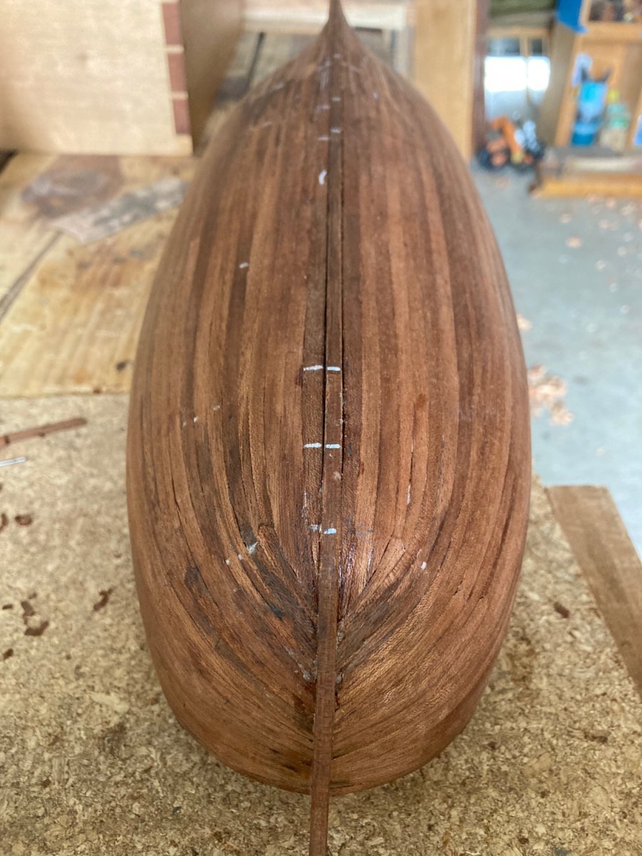
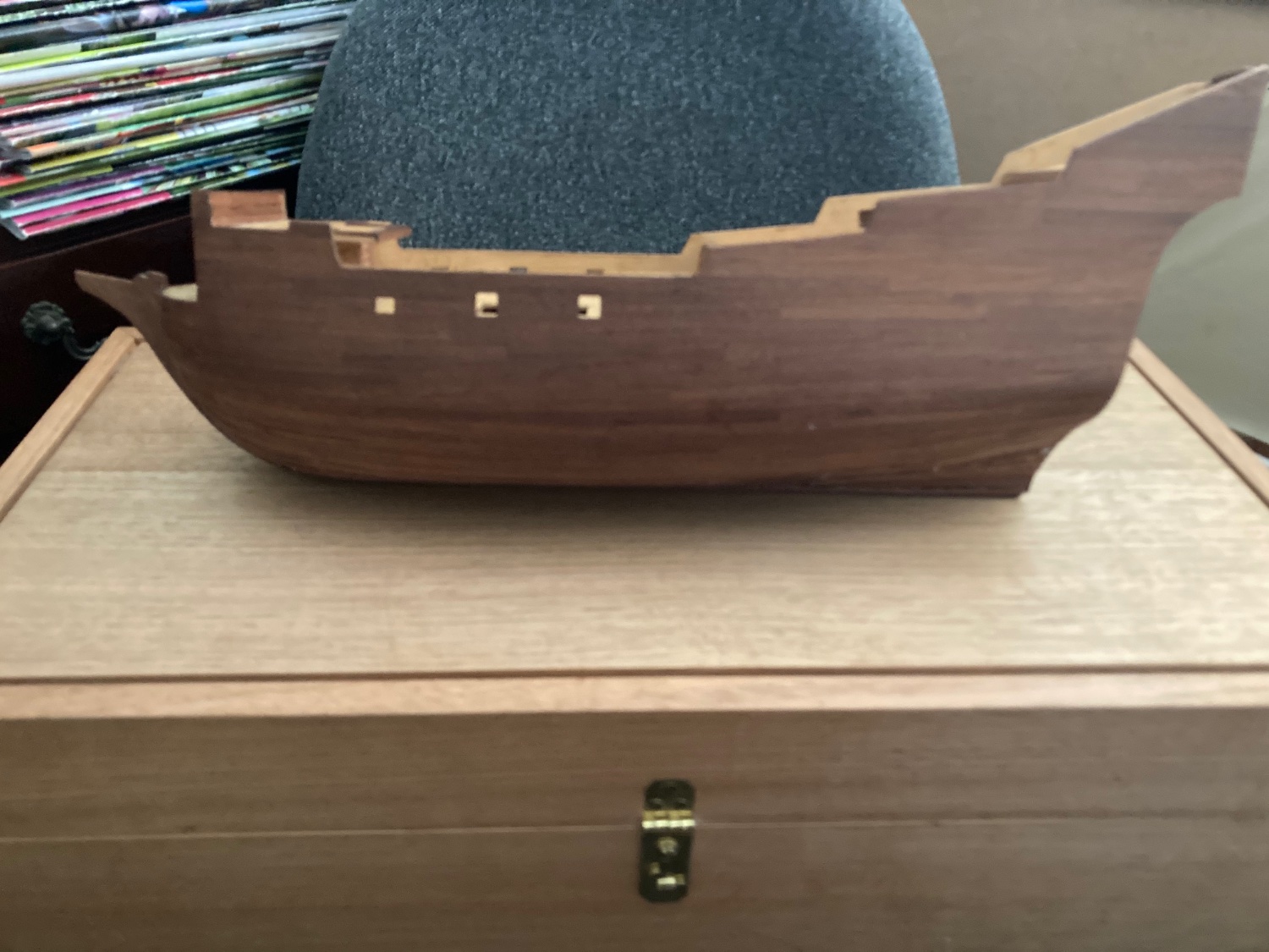
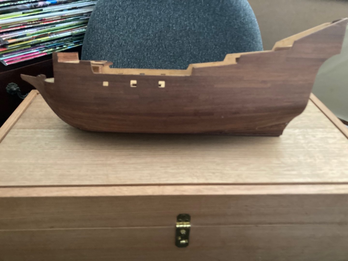
 After more years than I want to think about the hull is finally, finally planked. Finally. It isn’t perfect, but the worst crimes are below the waterline where I can hide them with paint. All in all I’m pretty happy with it. Some scraping and sanding will clean it up nicely and it shouldn’t need much filling. Next up is the rubbing strakes then I can start remodeling the deck.

-
Draque reacted to a post in a topic:
HMS Renard 1872 by Draque - 1/24 - POF
-
Draque reacted to a post in a topic:
HMS Renard 1872 by Draque - 1/24 - POF
-
mtaylor reacted to a post in a topic:
HMS Renard 1872 by Draque - 1/24 - POF
-
Tony Hunt reacted to a post in a topic:
HMS Renard 1872 by Draque - 1/24 - POF
-
Draque reacted to a post in a topic:
HMS Renard 1872 by Draque - 1/24 - POF
-
No Idea reacted to a post in a topic:
HMS Renard 1872 by Draque - 1/24 - POF
-
HMS Renard 1872 by Draque - 1/24 - POF
Draque replied to Draque's topic in - Build logs for subjects built 1851 - 1900
Thanks, Håkan. @Jaager said in an earlier post that on my plans the stations would have been spaced three frames apart and that I could work out my frame dimensions from that. Was this a standard way of drawing plans? If so, how do these dimensions look: Distance between stations: 1680mm Dividing by 3 gives 560mm for each room+space 560mm-305mm(1 foot) = 255mm (almost exactly 10 inches) So, frames 255mm sided and spaces of 305mm? So, is this about right (I haven't made the effort to taper the frames as they rise):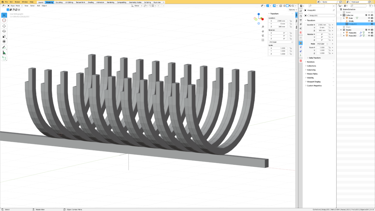
-
HMS Renard 1872 by Draque - 1/24 - POF
Draque replied to Draque's topic in - Build logs for subjects built 1851 - 1900
Thanks, everyone. Tony, thanks once more for your input. That was pretty much what I was thinking. I know these schooners would not have ever been expected to withstand any serious gunfire, but would room and space be sturdy enough to fire their own cannon from? Håkan, I somehow overlooked your Atlantica build and now, having had a quick look, I love it. I'll read through your build log properly as soon as I have a chance. I hope mine comes along as nicely as yours looks. @No Idea, to be honest, at this point I've got more information from Tony and Jaager and Craig than I've managed to dig up for myself. I'll be sending some emails out soon to some museums and historical societies in the hope that someone has some more information or a framing plan or a high resolution photo of one of the schooners framed up and unplanked on the slipway (I can hope, can't I?). I haven't had time for much work on the plans over the last few days, so I don't really have an update for the build log. I have had time to think about what I want to do with it and I'm starting to lean towards making a model that represents all five schooners, rather than just Renard specifically. The only information I have about Renard specifically is the RMG model, but I have photos now of the others. -
Old Collingwood reacted to a post in a topic:
HMS Greyhound by Srenner - Corel - 1:100
-
Draque reacted to a post in a topic:
HMS Renard 1872 by Draque - 1/24 - POF
-
Draque reacted to a post in a topic:
HMS Renard 1872 by Draque - 1/24 - POF
-
Draque reacted to a post in a topic:
HMS Renard 1872 by Draque - 1/24 - POF
-
No Idea reacted to a post in a topic:
HMS Renard 1872 by Draque - 1/24 - POF
-
 Srenner reacted to a post in a topic:
HMS Greyhound by Srenner - Corel - 1:100
Srenner reacted to a post in a topic:
HMS Greyhound by Srenner - Corel - 1:100
-
That looks really good, nice work. Especially considering you’ve only recently started using either program.
-
Draque reacted to a post in a topic:
HMS Greyhound by Srenner - Corel - 1:100
-
Tony Hunt reacted to a post in a topic:
HMS Renard 1872 by Draque - 1/24 - POF
-
Draque reacted to a post in a topic:
Flying Fish by MikeR - 1:64 (3/16" to 1 Foot) - from Model Shipways plans
-
ccoyle reacted to a post in a topic:
HMS Renard 1872 by Draque - 1/24 - POF
-
HMS Renard 1872 by Draque - 1/24 - POF
Draque replied to Draque's topic in - Build logs for subjects built 1851 - 1900
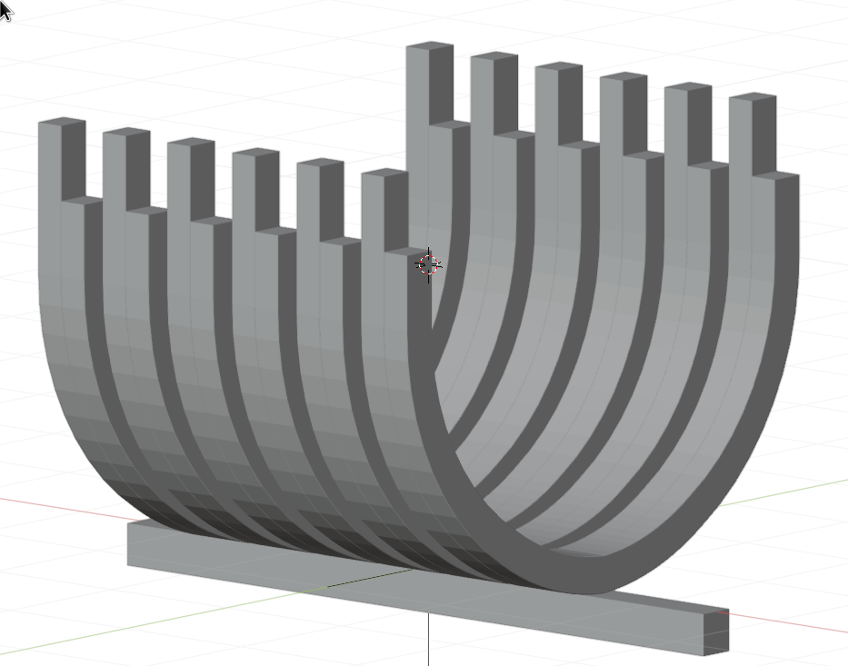
I love these old photos. Good find. I've made some decisions about this model. Basically, I'm going to build Renard like this: So, 1/24, plank on frame, fully rigged, planked on one side. I doubt that I'll have any crew figures though. I've been trying to work out what the framing would look like. A few posts back Jaager provided some figures which I used to make a rough model of some frames in Blender: The dimensions are: Distance between stations: 1682mm (~5'6") Three pairs of frames between stations Frame width: 200mm (8") Frame thickness ("moulded" per Jaager's post): 254mm (10") Keel depth: 280mm (11") Keel width: 254mm (10") Am I doing this right? The ketch model above appears to only have single frames with larger spaces between. The frames that I've drawn look very chunky to me.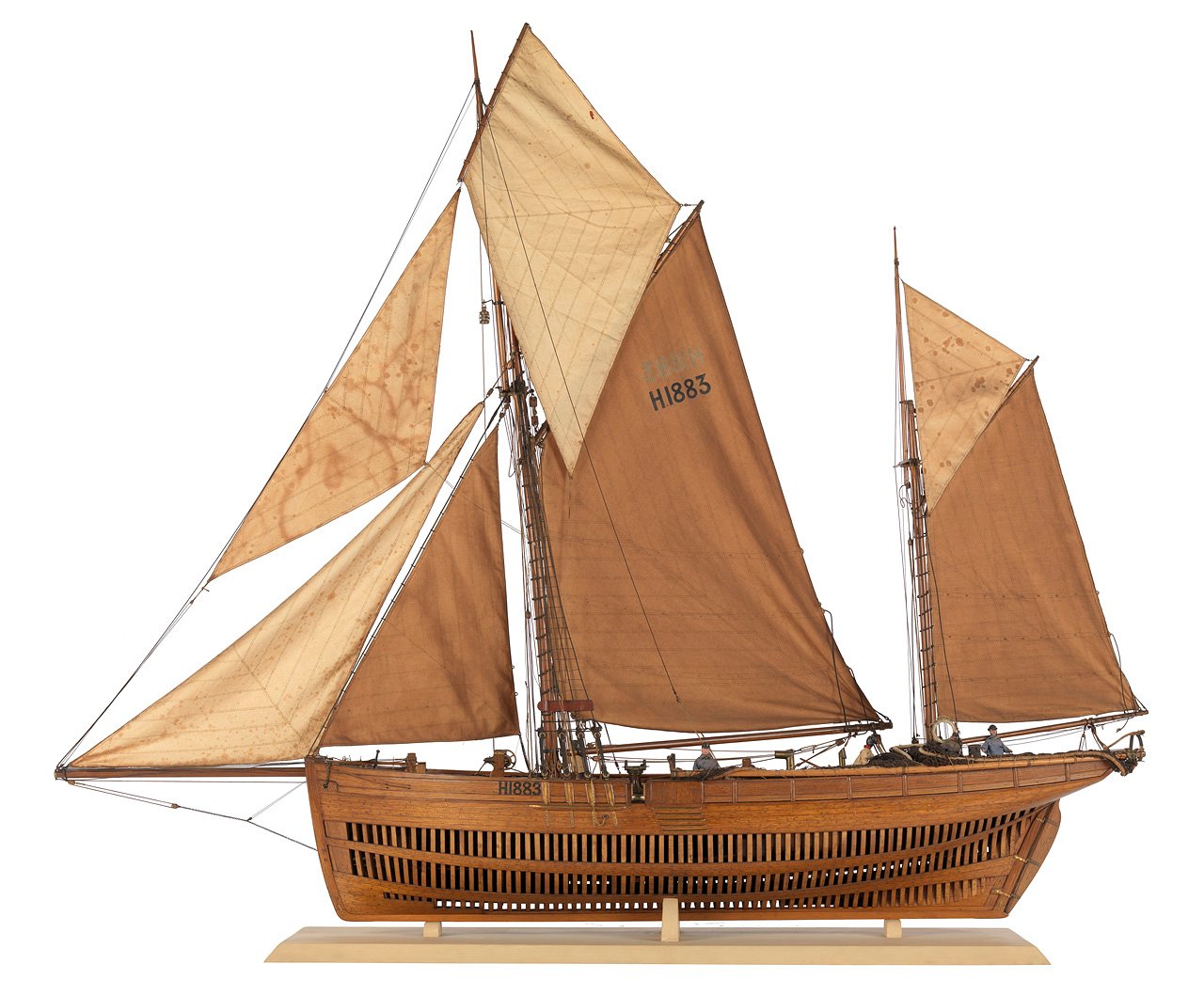
-
HMS Renard 1872 by Draque - 1/24 - POF
Draque replied to Draque's topic in - Build logs for subjects built 1851 - 1900
That last article was interesting. I wonder how hard it would be to get hold of a copy of the journal, or any of the journals or logbooks of the sailors on these vessels. I did a quick search on the ANMM website but found nothing. Your searching skills are definitely better than mine. Thanks again for posting these photos. -
HMS Renard 1872 by Draque - 1/24 - POF
Draque replied to Draque's topic in - Build logs for subjects built 1851 - 1900
Thanks again, Tony. I was busy typing away while you were reading my mind. It's great to see photos. Interesting that they have different colour schemes. Also, it looks like Alacrity (formerly Ethel) does have the clipper bow. -
HMS Renard 1872 by Draque - 1/24 - POF
Draque replied to Draque's topic in - Build logs for subjects built 1851 - 1900
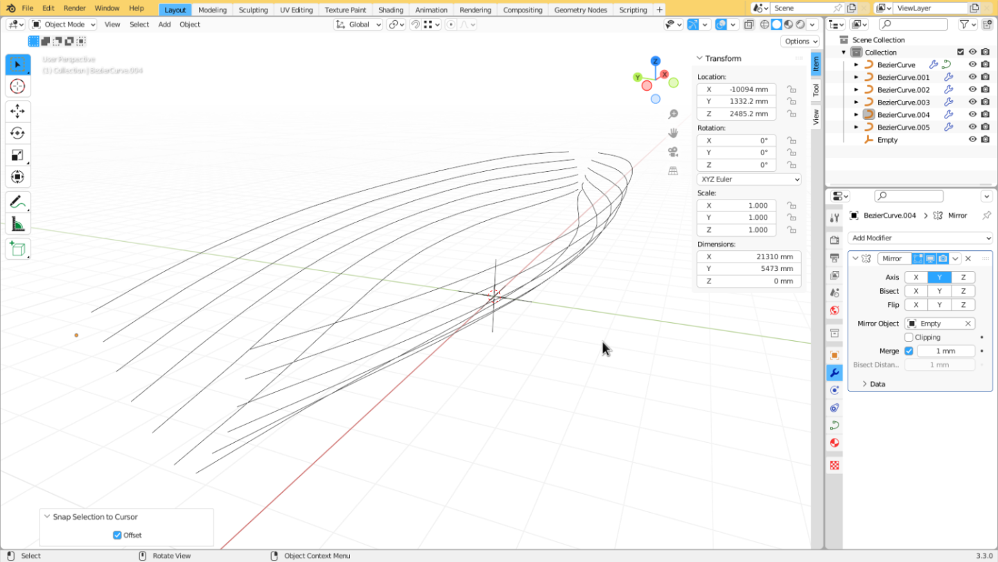
Thanks, Tony. Finding the plans was almost no work at all. After discovering the model, I just emailed the museum to ask and the very helpful and efficient person I spoke to there found them and posted them. I don't remember what it cost, but I had the plans in a couple of weeks. I also wondered about the bow. I figured they probably just went with a simpler and cheaper version for the naval vessels. Maybe Ethel had the clipper bow and these drawings were based on her. In any case I like the simple bow of the Renard model. I don't know who drew the plans but they do have Cuthbert's name on them, along with two others. I don't have a photo that shows them clearly and I don't have the plans handy to check. I'll post a photo when I get a chance. I didn't know any photos of these vessels existed. I would really like to see them. Do you have any idea where I can find a copy of Bastock's book? The local library here doesn't have it and I'm not in Sydney any more so my library options are limited. Abebooks has some copies but they're asking for more money than I'd like to spend to look at a couple of grainy photos. I don't even know where to start looking for the originals. I've started drawing up the lines in Blender. I measured as precisely as I could off the plan and recorded all my measurements in a spreadsheet. I used the spreadsheet to scale everything up to full-size dimensions (just multiply everything by 24). I used the full-size dimensions to create coordinates for the curves in Blender. After I've got all of the lines smoothed out and agreeing nicely I can scale it back down to model-size and any errors from distortion of the plans or my measurements should be negligible. It's working well. I can build up the 2D lines as a set of Bezier curves then offset them along the third axis to get a 3D shape,for example: The curves need a bit of tidying up and I'm undoubtedly going to have to tweak them to get the waterlines to match the body plan, but so far they do at least look like the plan.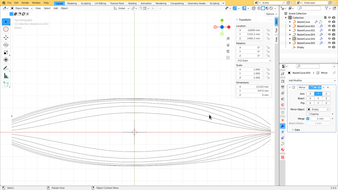
-
3D Brig 'Rose' in Blender 3.3x
Draque replied to 3DShipWright's topic in CAD and 3D Modelling/Drafting Plans with Software
This is fantastic work. Please keep posting updates. -
HMS Renard 1872 by Draque - 1/24 - POF
Draque replied to Draque's topic in - Build logs for subjects built 1851 - 1900
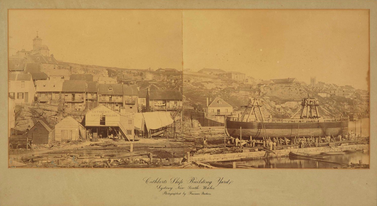
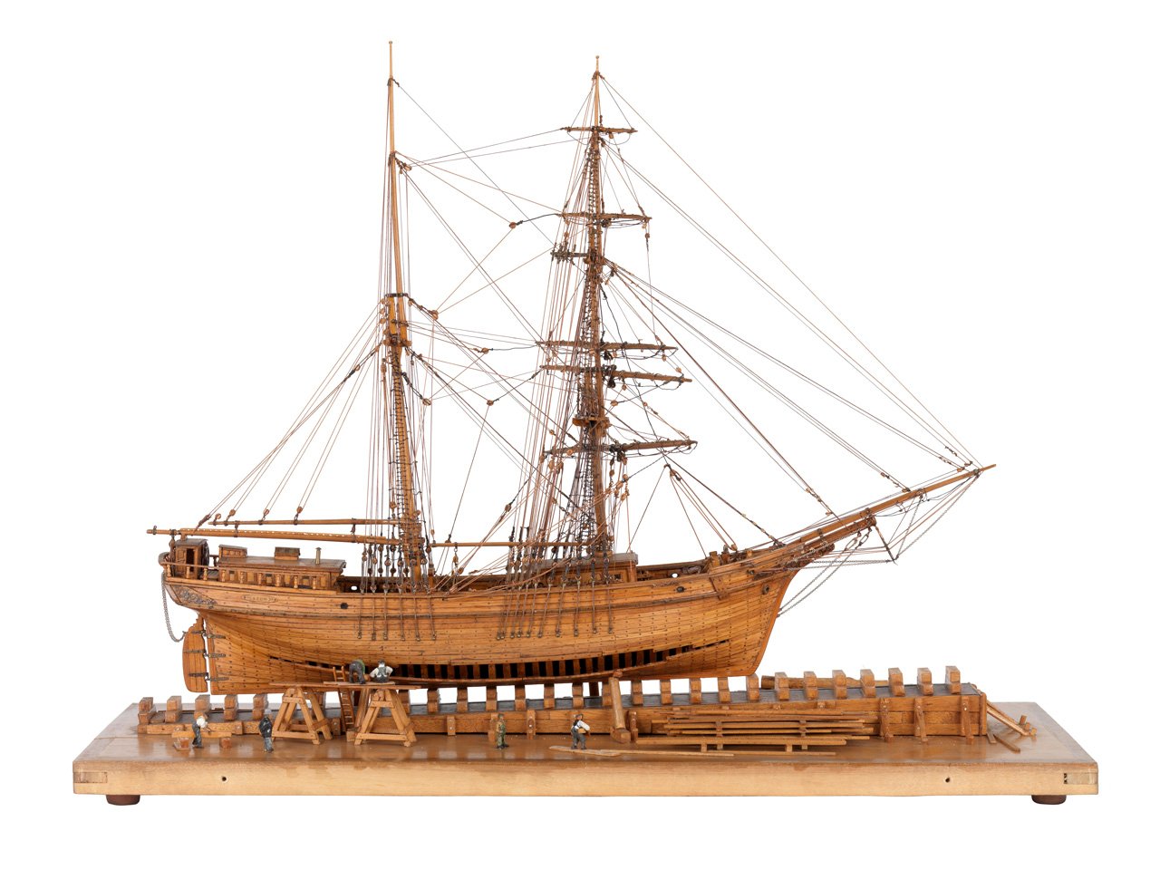
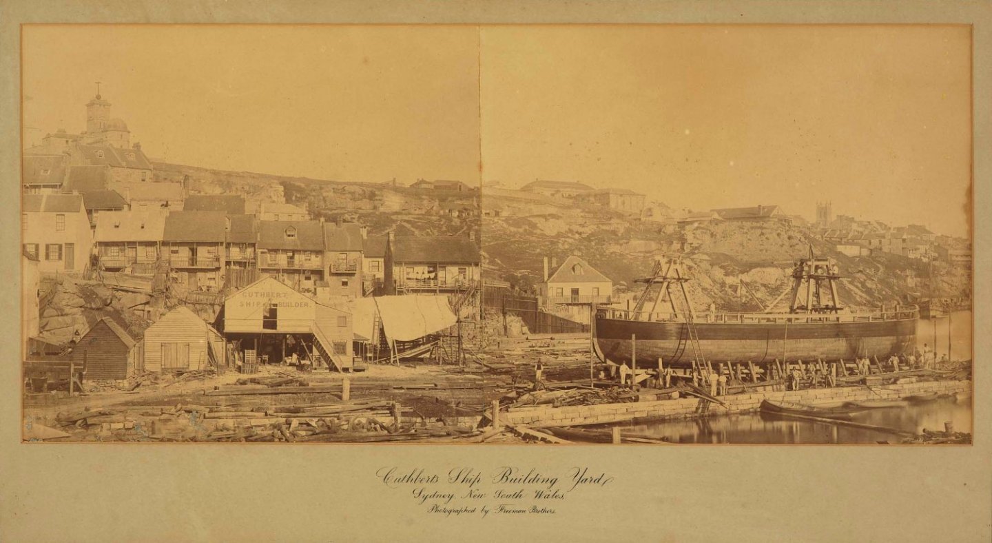
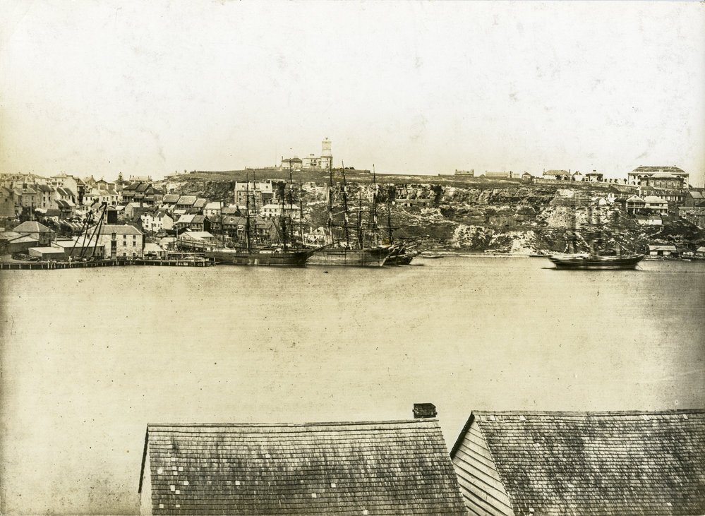
Thank you, Wefalck and Druxey. Regarding the use of a scale rule; please don't think that I'm ignoring or rejecting this undoubtedly good advice, it's just that my circumstances make it a bit impractical. I live in a regional part of NSW and I would expect to be waiting at least two weeks for delivery, even if it weren't Christmas time and I'm hoping to make some progress in drawing up my plans before I need to get back to work. Also, because I'm building in the same scale as the plan I'm working from and I work in metric, it altogether seems more sensible to me to measure directly off the plan in mm and punch those numbers into the software I'm using. Craig, I printed out your scale, but my printer got it wrong and it came out slightly oversize. I could probably solve that problem but I don't have the patience to argue with a printer. I've been researching, trying to gather up as much information about how Renard might have been built, in particular hoping for something that will tell me specifically how it was framed. A framing plan for Renard or a photo of the ship under construction seems too much to hope for, but there is some useful information out there. First, I went looking for frame models of similar sized vessels from the 19th century: Those are the best I've found, all of them from the National Maritime Museum's website. Not all schooners, but similar sized vessels, not too distant in time from Renard (I really like that ketch, I might have found a future subject). I think they're all British-built, though, so I wanted to know if colonial ship-building followed the same practices. I also wanted to know a bit more about the shipbuilder, John Cuthbert, and his shipyard at Miller's Point, thinking there may be some clues there. I found scraps of information about Cuthbert here and here, as well as some photos of his shipyard (no exposed framing visible, unfortunately): but was stunned yesterday, when I found this: https://www.nautical-association.org/publications-store "A Shipwright in the Colonies" is a 187 page research paper that gives about as thorough a biography as I could ever have hoped for. I haven't read all of it yet, and the section that covers Renard and her sister ships is not quite as detailed as I would like, but there is some information here: "With an overall length of 80 feet, a hold 9 feet 6 inches deep and a beam of 18 feet 6 inches, the hulls of these naval schooners reflected the best in colonial construction and materials. Fastened entirely with copper, the vessels were built with ironbark keels, black butt and blue gum frames, kauri pine planking and sheathing of 18, 20 and 22 ounce Muntz’s metal over chunam." There's also this: "The use of the diagonal technique by Cuthbert in his commercial vessels promoted new standards for the colony, although the idea appears to have been transferred from England to NSW much earlier." So the question I have is, would Cuthbert have used diagonal planking in his naval vessels? If so, would that have affected the dimensions of the framing?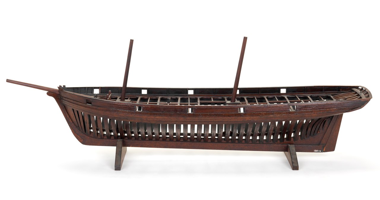

-
HMS Renard 1872 by Draque - 1/24 - POF
Draque replied to Draque's topic in - Build logs for subjects built 1851 - 1900
One more thing... Could the position of the wale be derived from the planksheer? I don't know enough about how these things are done, but wouldn't the wale follow the same line just a short distance below? Edit: Actually, never mind, now that I think of it that doesn’t make a lot of sense. I was thinking that the deck beams would sit on top of the wale, but of course the wale is on the outside of the framing. -
HMS Renard 1872 by Draque - 1/24 - POF
Draque replied to Draque's topic in - Build logs for subjects built 1851 - 1900
Thanks Jaager. All of this is exactly the kind of feedback I was hoping for. I can understand this. If the futtocks and keel were just butted and nailed together I would think the same. It's the neat interlocking of the various pieces of wood that interests me. And the curves, of course; I would probably never have developed an interest in boats at all if not for the graceful shape of a hull. A half hull is an interesting idea. I've wanted to do one of those in the past, but never considered it for Renard. It might be a good way of checking that my hull design is fair and get a sense for how the planking will run before I commit to the bigger POF build. When I do go ahead with the full build, I would like to be able to point to it and honestly say that it accurately represents the ship as it would likely have been built. I can be happy with a simplified or incomplete reconstruction, but wouldn't do something that I knew to inaccurate. Thanks again, Jaager and Craig and anyone else who's taken an interest. And please keep coming up with information and problems for me to solve. -
HMS Renard 1872 by Draque - 1/24 - POF
Draque replied to Draque's topic in - Build logs for subjects built 1851 - 1900
Thanks, Jaager, for putting all of that together. I'll need to spend some time going over all of those numbers before I can make proper sense of it. Part of my attraction to POF, and wooden boats in general, is the internal structure and joinery. I know I won't be able to exactly replicate this particular ship, but if I can frame it up using the principles that were used at that time and place for this type of ship I will be happy. This will be my first scratch build, but I'm a furniture maker, so the woodwork isn't beyond my abilities. I just need to make sure I'm working to an accurate plan. -
HMS Renard 1872 by Draque - 1/24 - POF
Draque replied to Draque's topic in - Build logs for subjects built 1851 - 1900
Druxey, that seems like good advice. My problem is that I can only get metric scales from the local office supplies store and these plans are in that other system. I mean to build at 1/24, so I can just take my measurements straight from the plans and multiply manually whenever I need to. I'm drawing up my plans on the computer as vector graphics, so I can adjust the scale that way too. Craig, thanks for checking on that. I'll get more precise measurements later, but your figures seem realistic. -
HMS Renard 1872 by Draque - 1/24 - POF
Draque replied to Draque's topic in - Build logs for subjects built 1851 - 1900
Thanks, Paul. Craig, just measuring off the plan with a ruler (so, not super precise), I get about 2.6mm at the midship station and about 1.7mm at the stern. At 1/24 (the scale of the plans) that gives about 62mm and 41mm. I don't know whether the garboard would really have different thicknesses along its length, maybe there's a bit of inaccuracy in the plans.