HOLIDAY DONATION DRIVE - SUPPORT MSW - DO YOUR PART TO KEEP THIS GREAT FORUM GOING! (Only 13 donations so far - C'mon guys!)
×


Mark Pearse
-
Posts
820 -
Joined
-
Last visited
Content Type
Profiles
Forums
Gallery
Events
Everything posted by Mark Pearse
-
 well done again Mike, I like the way you are adept at using technology, & without losing the craft of your work. Absolutely lovely looking yacht & model. MP
 -
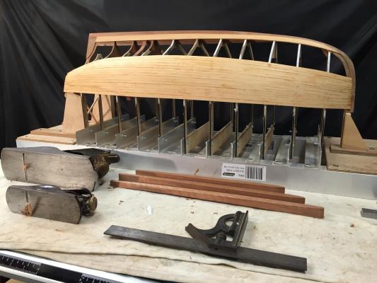
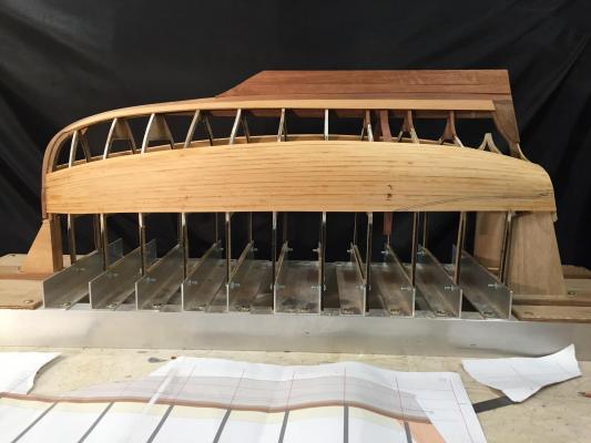
thanks everyone for your interest & comments I've started work on the keel. I have some nice old Queensland Maple, which I selected because it planes well (unlike most native timbers) & yet is hard enough to resist most knocks (unlike most native timbers that plane well). This timber was logged almost 70 years ago so it should resist further warping. I'm building it up from thick longitudinal laminations. However, I picked up a measurement error so there's going to have to be another 4-5mm lamination in there as well. The reason for working on it now is that the shape of the keel timber immediately below the garboard is related to the keel shape etc, so roughly shaping it now will help in shaping the lower parts, even though the garboard is done. I'll glue the keel laminations together, shape them & leave it unfixed to the hull until after the planking is completed. Some brass pins will be used to accurately locate the keel, & will also give better purchase for gluing. One thing that is really showing is how far aft the centre of lateral resistance is on the hull. I take it that this is because of the power of a gaff mainsail, & the way the long boom usually overhangs the transom so there's quite a bit of push a long way aft. thanks, MP there's another thin lamination required in addition to these 2 outlined & in position
- 411 replies
-
- 13
-

-
thanks guys, Patrick, yes it was a bit tough to swallow that I wouldn't get the chance to sail her, but I reasoned that it was probably no more work to rig & sail our real boat ... so the pain dissipated. It would still be possible to reverse that decision & make her sailing, we will see.
-
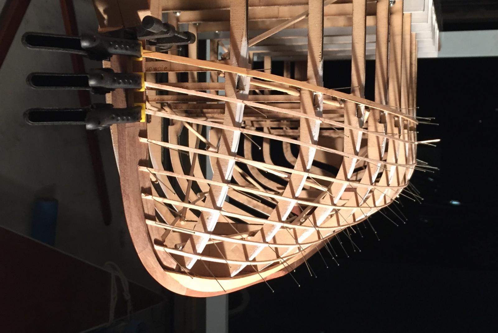
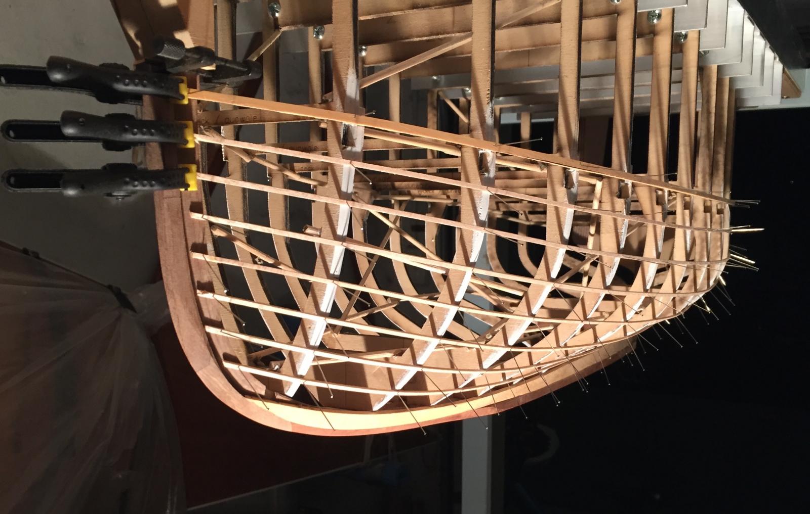
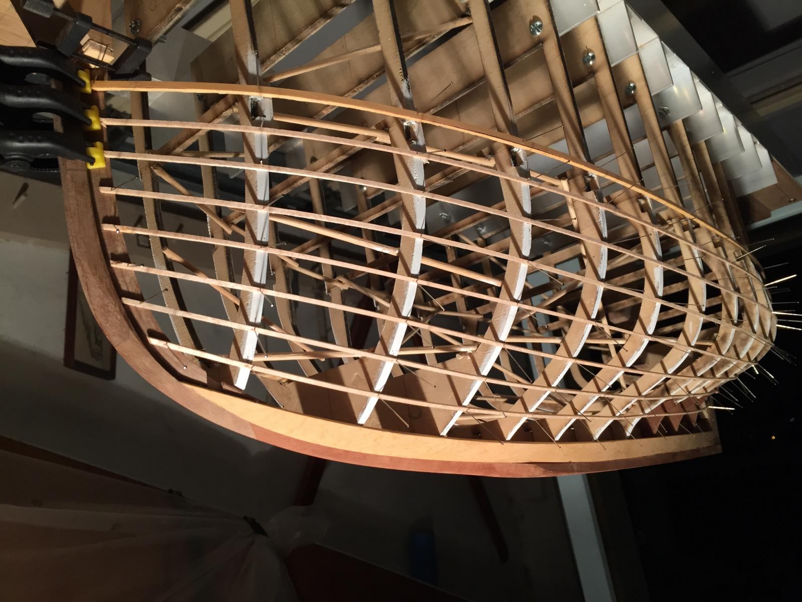
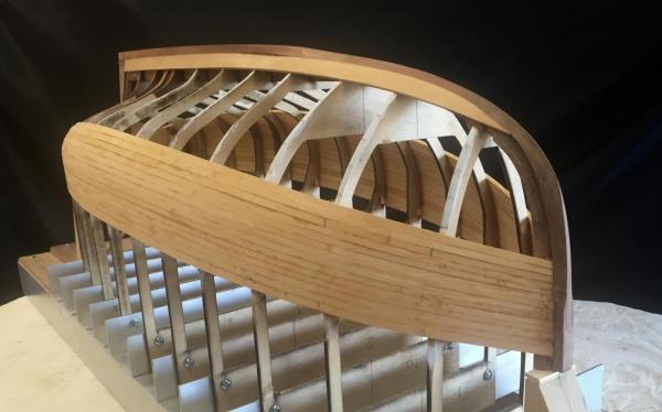
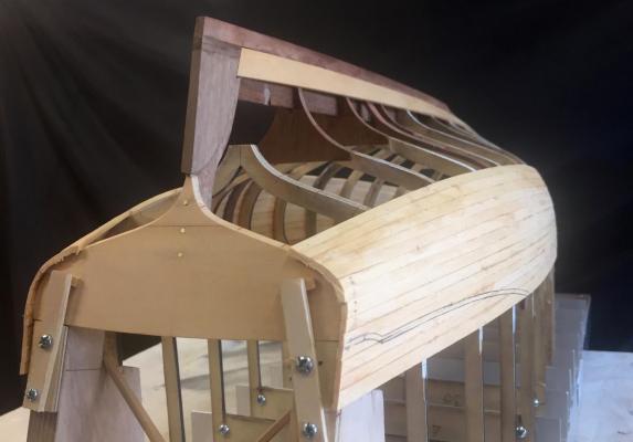
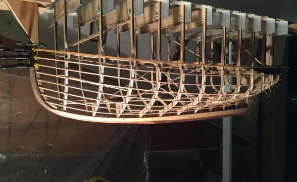
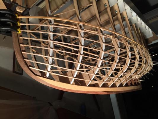
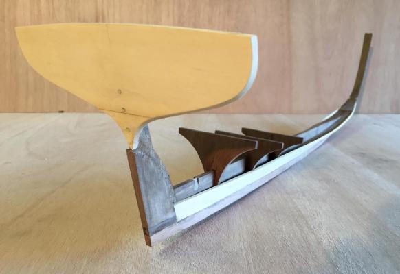
A couple of issues with the model had to be sorted & so progress was fairly slow while I was considering them. I've decided to make this a display model only, not a sailing model; also I was finding that after having done about 1/3rd of the planks it was still too flexible to be able to fit ribs into this hull, if I had continued as is. The Huon Pine planking is flexible & the ribs would have to be also v flexible to not distort the planking when fitting them. I did some tests with strips of Spotted Gum & it just was not going to work out, the Gum takes a fair bit to bend & the Pine would have been distorted by that. So, the plywood moulds are staying. Ultimately it is more important to me that the hull shape is accurate to the design rather than just the model looks nice. So, the hull was slipped off the moulds while it was still possible, the ply cleaned up & the planking was glued to the moulds. The planking in the stern area will need to be trimmed, the profile has been roughly pencilled on. Shown up side down you can see the hull shape somewhat, & you can certainly see that they would make good centreboarders. thanks, bye for now MP


- 411 replies
-
- 14
-
-
Hi Mike nice progress again, she really is starting to look like a yacht rather than a model. Lovely stuff. There may be no problem with the tacking of the jib around the forestay, if you let the sail blow across the boat as the boat tacks rather than winching the sail across, the sail blowing around will pull the sheets with it. It certainly works for a full sized boat & there's no reason it won't work that way here too. She will be slow to tack as well, which will possibly help. Mark
-
Hi Mike, just a detail on the rigging plan: the sheets of the jib, the outer headsail, need to go around the forestay, which will be at the stem of the boat. They may have a permanent stay at the end of the bowsprit, as this sail would probably be dumped as soon as the weather got difficult, & it certainly would not have had it hanked on to the stay, but I would be pretty sure that they would have had a stay at the stem as a permanent thing so these sheets must go outside the stay. Just one comment on the issue of extra weight within the hull itself from the RC equipment, it is possible that this boat had some ballast in the hull & not all of it in the keel. It makes a hull roll more kindly, with less whippy action. I have no idea if they did or not, as in this case the ballast would need to be fully secured from coming adrift. So maybe you don't need to be concerned about not have all the weight as low as it can go in the hull. hope you don't mind the commentary, best MP
-
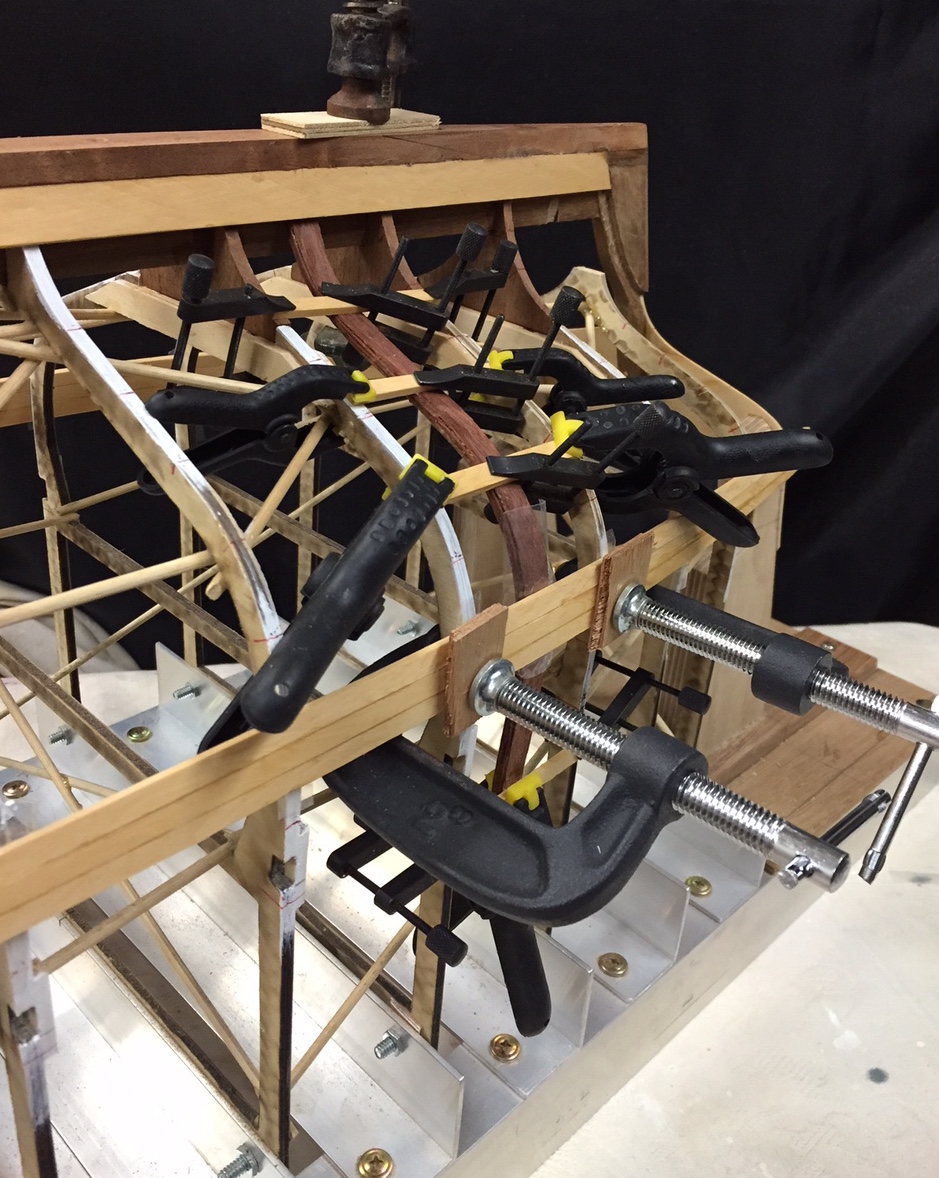
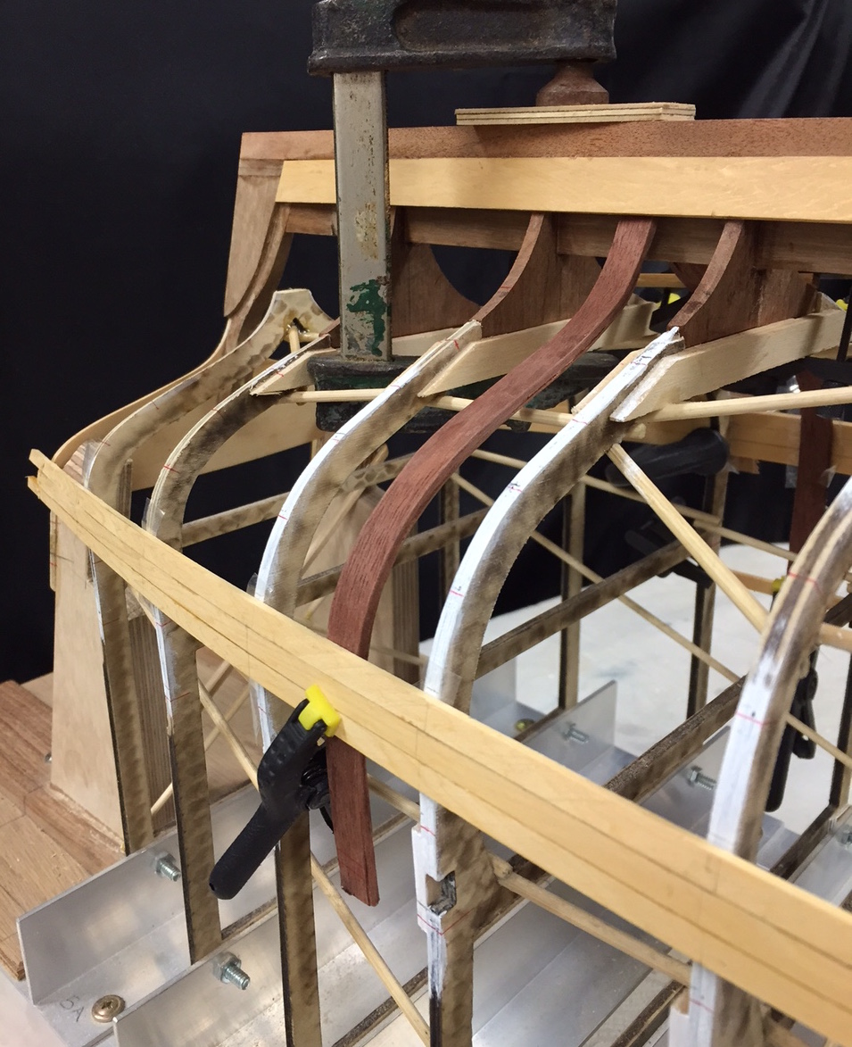
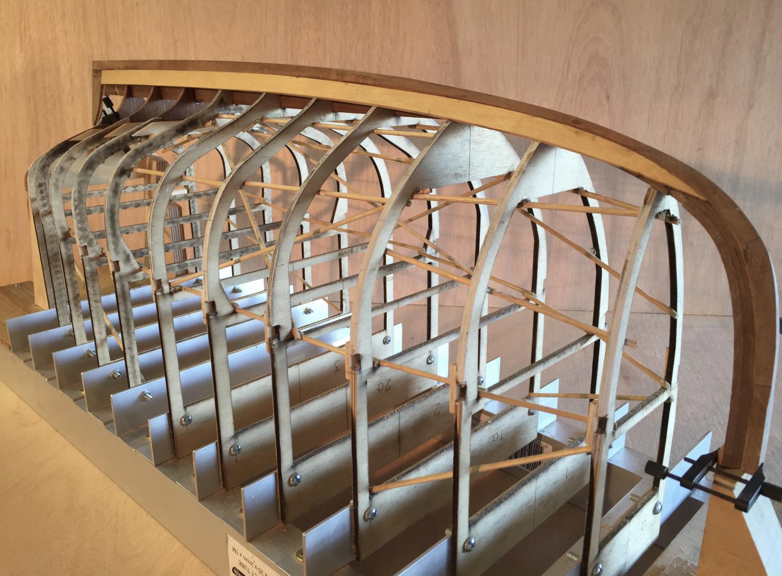
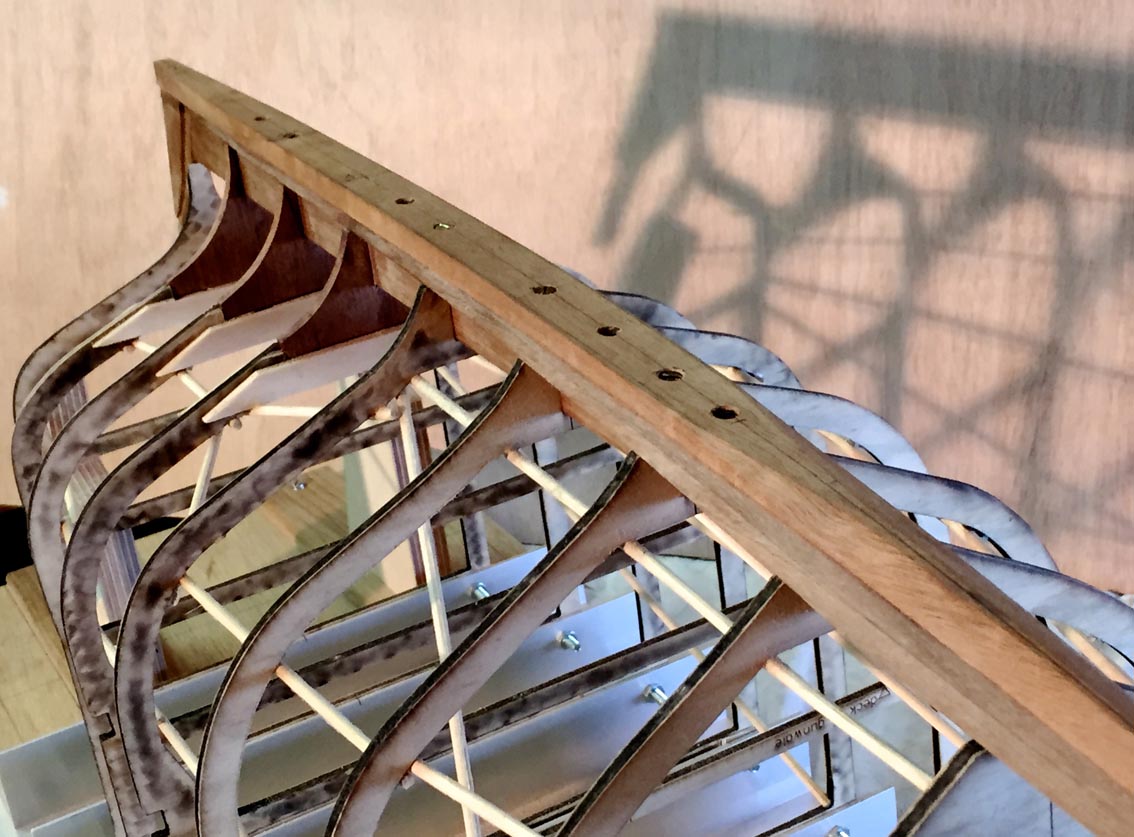
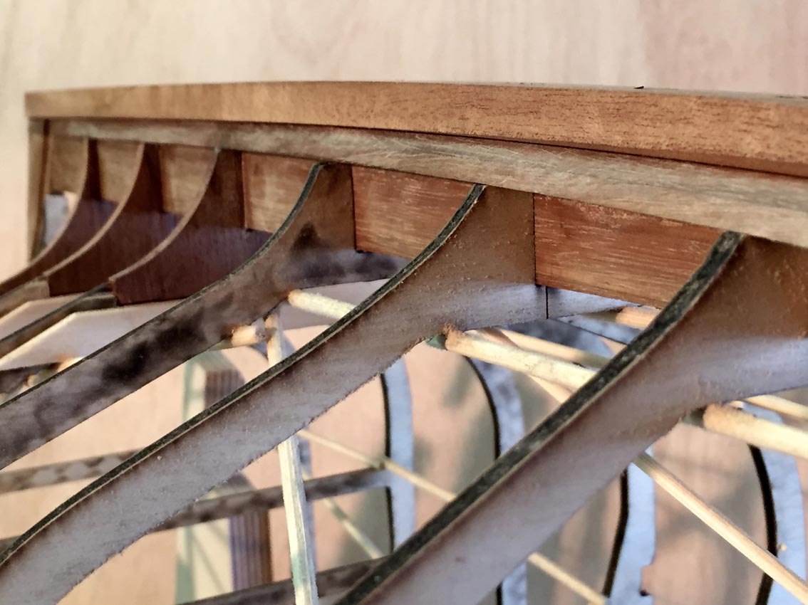
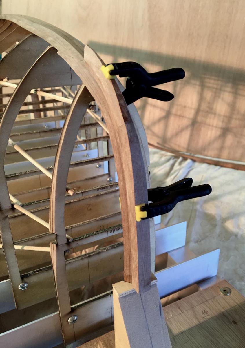
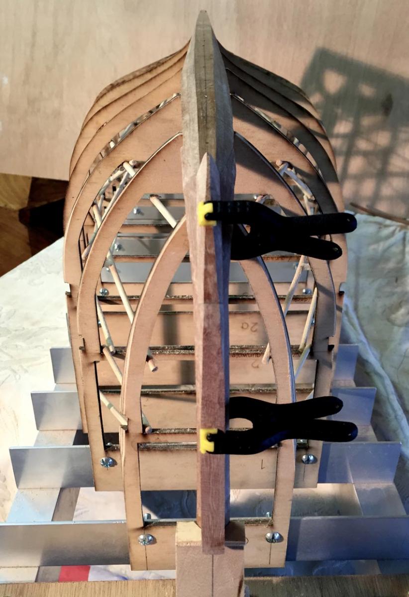
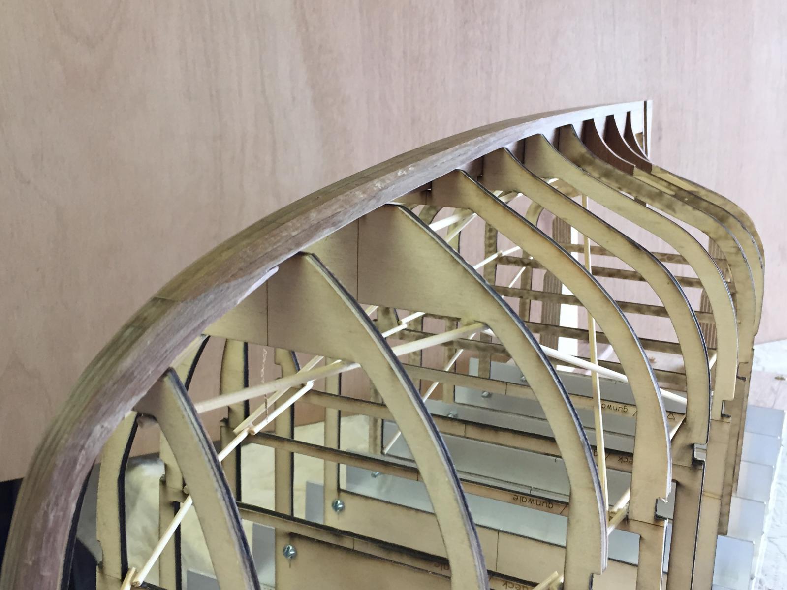
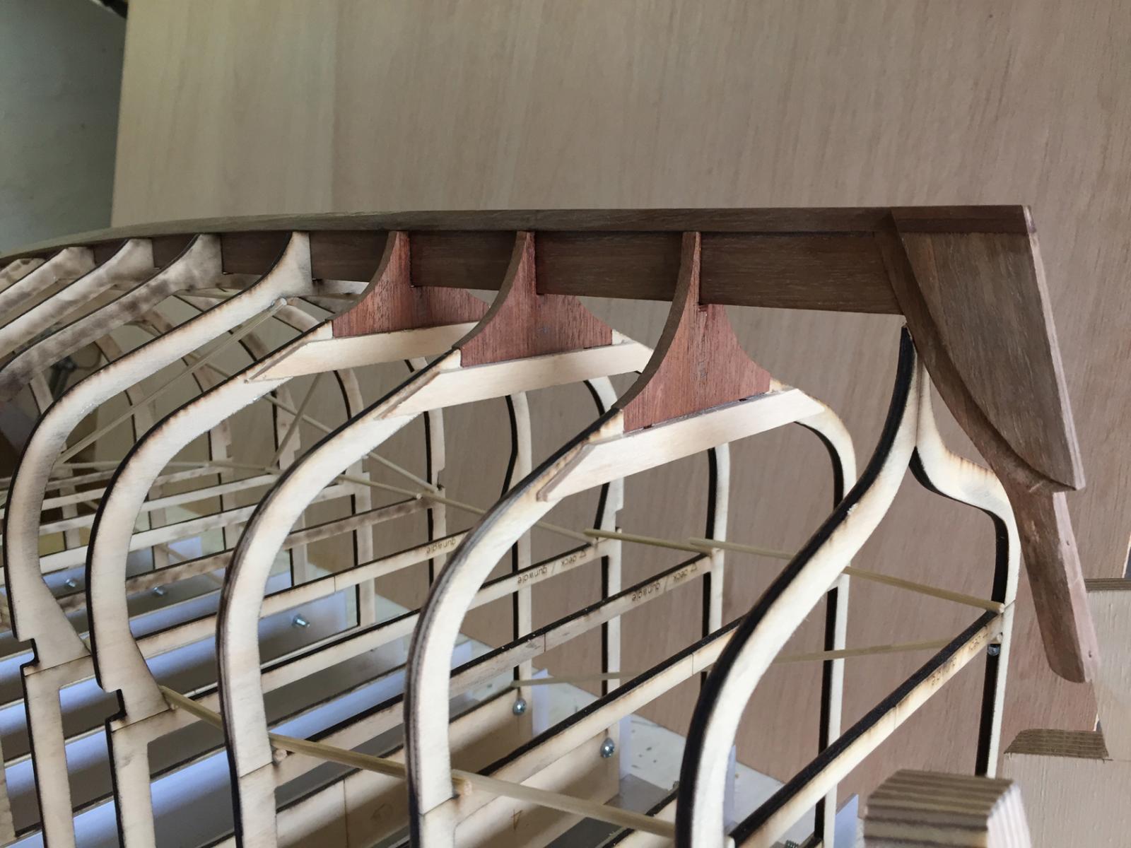
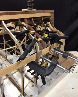
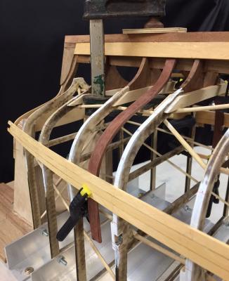
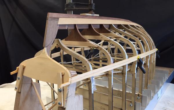
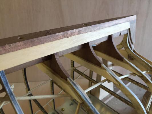
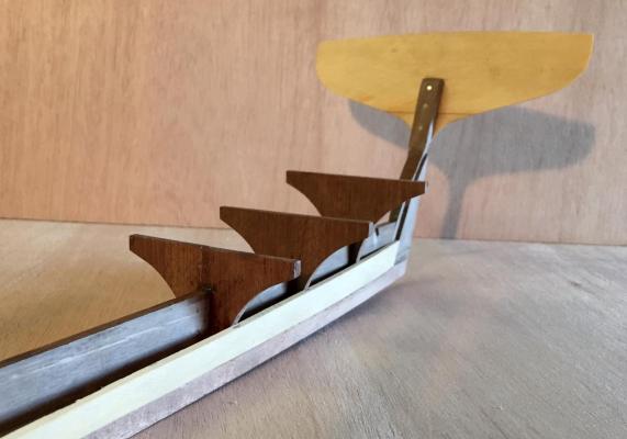
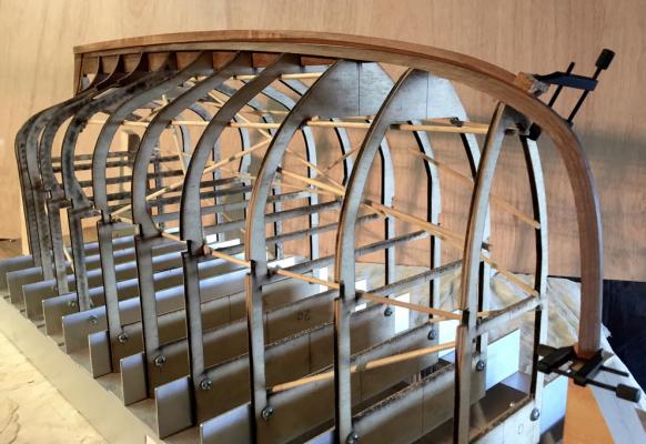
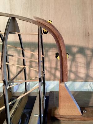
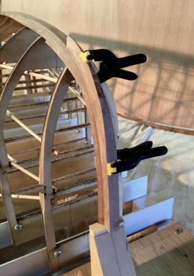
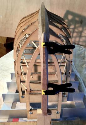
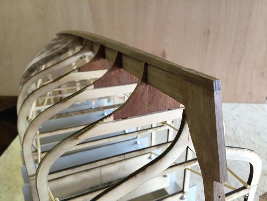
I've noticed that the planks spread a little away from the moulds, perhaps it's because there's only 3 planks per side on, but I decided to put in at least one full frame & deck beam now as it's going to be easier now than when more planks are on. If that doesn't seem to be enough then I may do more, but we'll see. The frame I chose to make is right at the edge of the raised deck. I cut some 10mm strips of hardwood veneer - Jarrah - & glue laminated them into shape by some judicious clamping & hopeful intentions. The photos show the starboard one clamped & glued in place, & also the port one afterwards, slightly sanded & clamped back in the approximate position. It's still about 8mm wide, which might be reduced, but in any case I never intended the interiors to be accurate to scale & construction so it's ok at that width. The veneers were quite easy to get into position, I was unsure of how difficult this would be, but it was quite easy & the resulting frame is good, stiff enough & also springy enough. Because the planking lines at this point of the hull swell outwards by perhaps 0.5mm, & the shape I made with clamps & battens doesn't have any of this swell, I hoped that they would be able to expand a little if I wanted, to suit the actual shape. Next is to make the deck beam, some simple knees & then glue it all together. bye for now MP
-
Hi David, the stations are about 60mm apart - a little under 2.5" - if this is wide then I didn't realise it in my lack of experience. But I'm confident that I'll work out something if it does become an issue. I can see a couple of possibilities: the planks are about 0.5mm thicker than scale, to allow for some of this; I might be able to work out some sort of jig to hold them in line while the glue hardens ... but I think that the run of planks are quite close to how they would be in reality, & the width is certainly about right at a scaled up width of about 70-75mm maximum. The timber is very supple, so it will take shapes well without requiring heat - but if heat will help then heat it shall receive. Any suggestions? thanks, MP
-
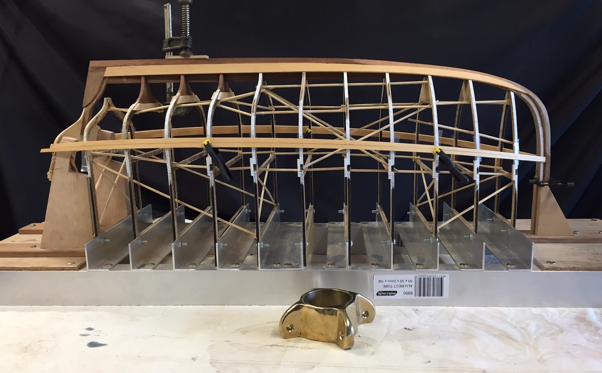
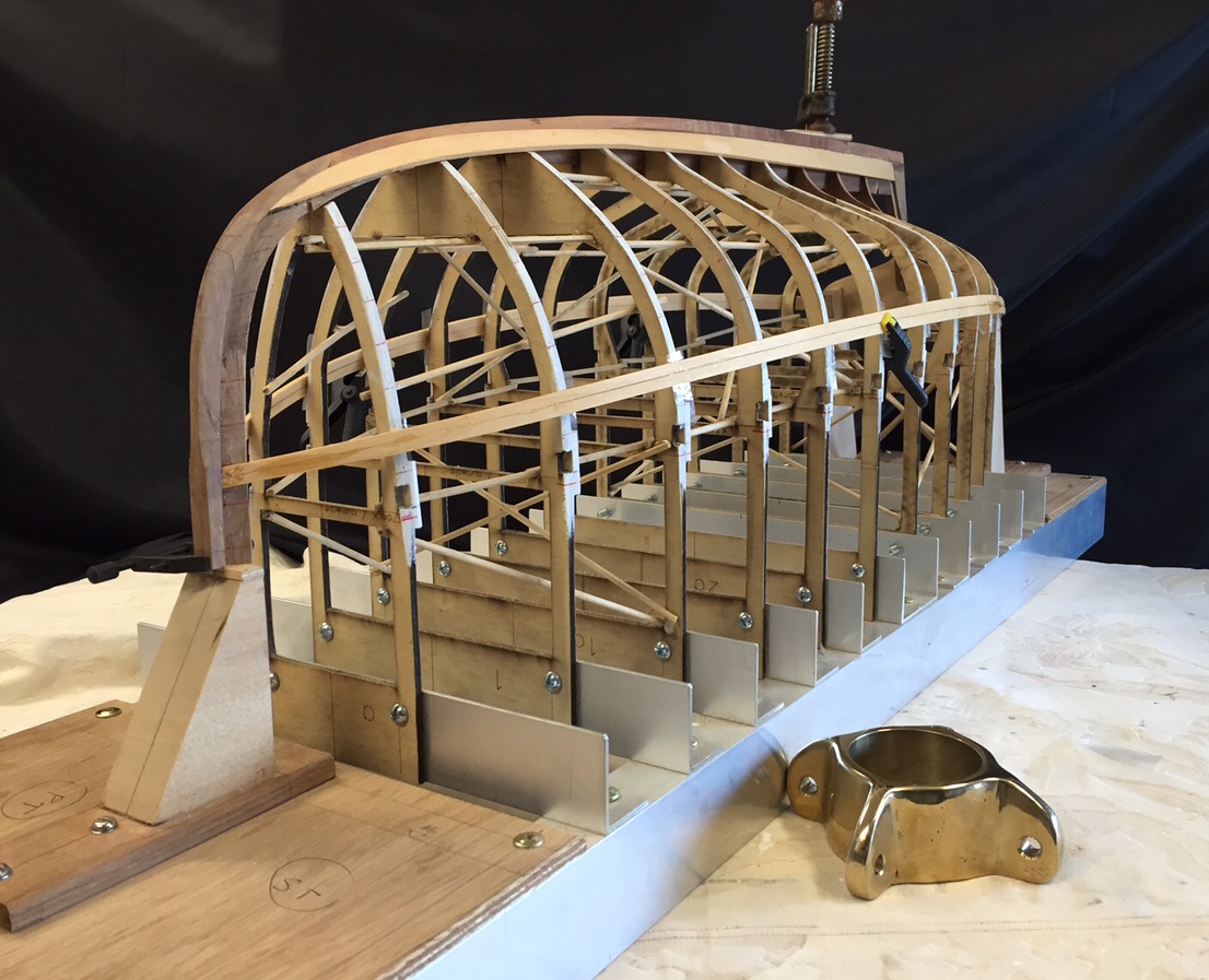
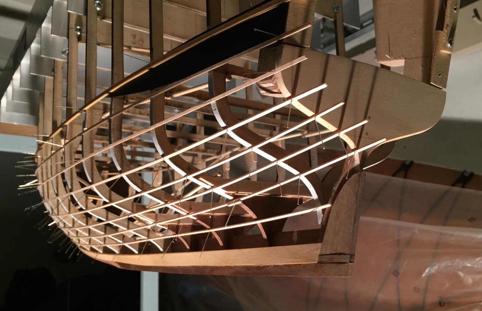
Hi there I finished fairing the moulds & have done a few planks. The intention is to first do a band of planks from the top edge of the transom down, to help stabilise the whole thing. There are some planks above this line due to the raised deck design, . When there's what seems to be a stable band of planks I'll probably start planking back up from the garboard. They are going on well, I've been using toothpicks at the stem & transom to help hold the planks in position - they will want to pull away under the tension on the planks, but the glue gets slippery & it would be a bummer if a plank slipped & set in the wrong place. The toothpicks act as pegs & hold the planks in place while the glue goes off. An interesting scale comparison is a new casting for our boom. hanks


- 411 replies
-
- 18
-
-
Clear now, & very interesting Bob - have you ever seen one configured in this way?
- 127 replies
-
- 2
-
-
- dragon class
- yacht
- (and 1 more)
-
Hi Bob she is very pretty & really looks just like a dragon: elegant & patrician lines. I read that they were designed to have 2 bunks, I imagine they're pretty tight down below. One question: earlier you said " The cross member in the hull is the aft cabin bulkhead support." I don't really know dragons, but that looks like a traveller rail to me, for moving the main sheeting position up or down. Maybe they've put it on top of a bulkhead or something. Another question - is that 2 pieces of noodle as a working stand? ta, Mak
- 127 replies
-
- 3
-
-
- dragon class
- yacht
- (and 1 more)
-
John as an avid "Afloat" reader I learned that you use Privet in your models - where do you source the timber? Another question: what glue do you prefer to use? thanks, Mark
- 745 replies
-
- 1
-
-
- francis pritt
- mission ship
- (and 1 more)
-
thanks Patrick & others, I am looking forward to seeing the keel on, & might even do it sooner than later, so that I can enjoy the effect on being able to better see the hull shape You can see clearly the way the water exit is clean despite the voluminous hull, it's my theory on why they sail well for a tubby boat. MP
-
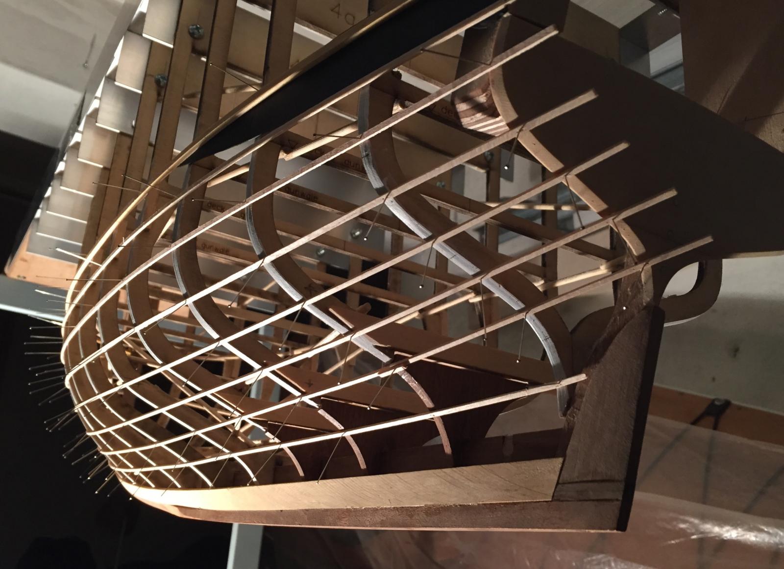
Hi I've been lining off the moulds for the planking using strips of balsa wood. The balsa has the advantage of being easy to cut into strips, easy to pin, & is fairly even in bending, but they are delicate & get damaged so easily. The planks themselves will be about 6mm maximum width, or about 72mm to scale. The plan is to: finish the lining off; mark this on to the moulds; make final adjustments to the moulds. I hadn't thought that more fairing would be needed, but the balsa battens laid along the actual lines of the planking showed that there is still some wobbles. I mocked up an approximation of the curved cockpit gunwale capping piece in black cardboard, it's not obvious but you can see it in the photos. This is the line that the topsides will be trimmed down to after the area is planked. You can see that a stealer plank is probably necessary, near the turn of the billed at the stern, I'm not sure exactly, but I think that where it wants to go will become clear when planking. thanks, bye for now MP


- 411 replies
-
- 15
-
-
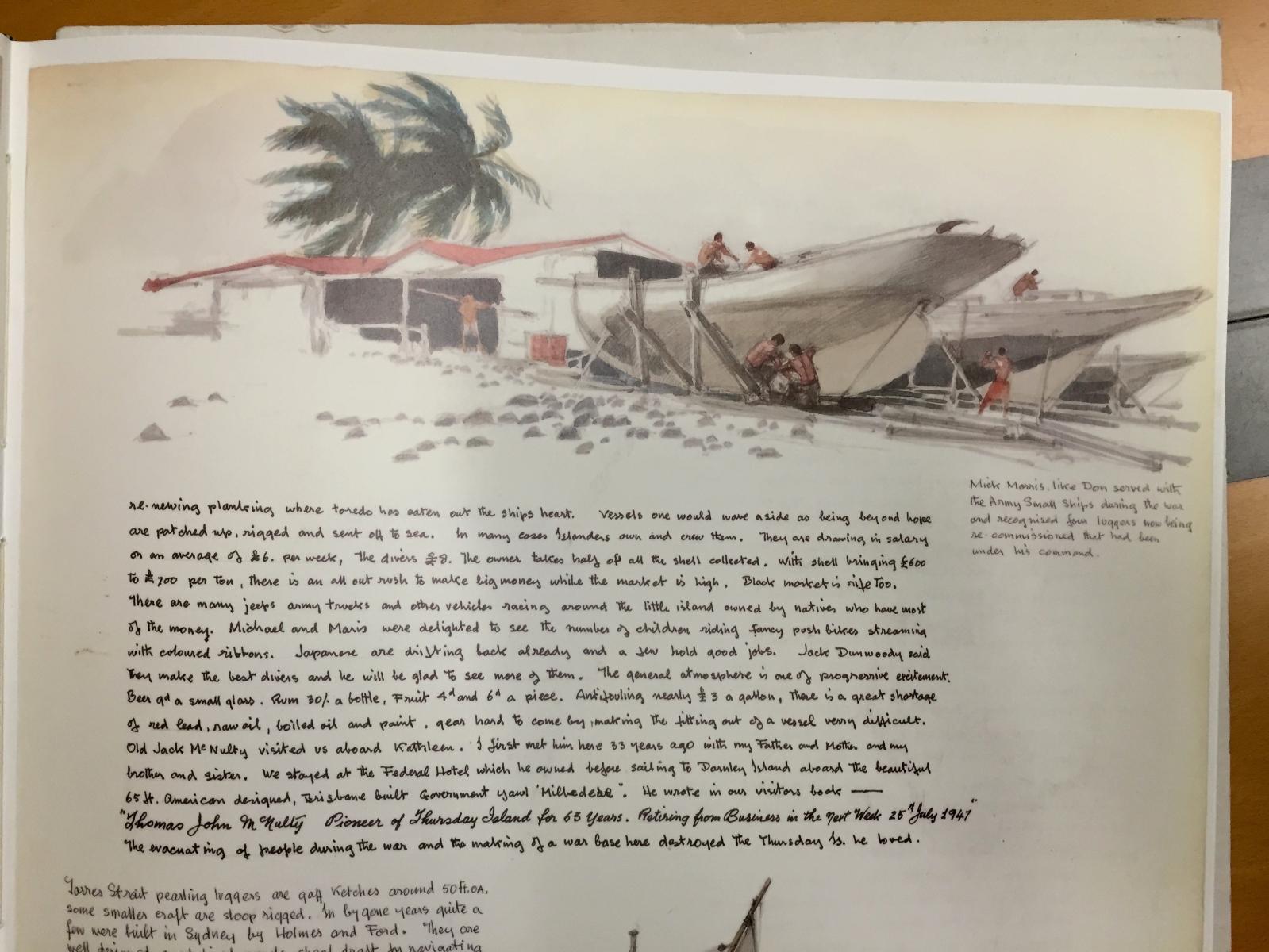
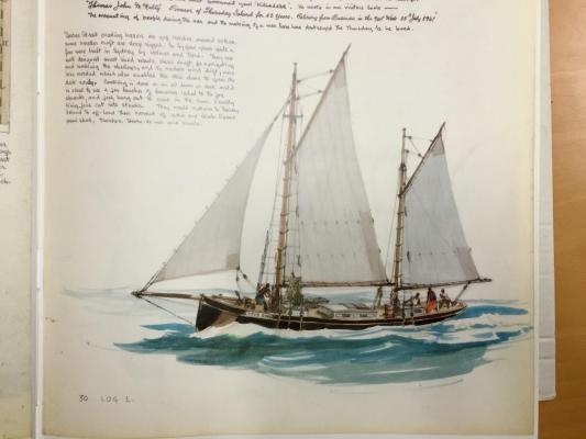
Hello John attached are some images of TI luggers, from Jack Earl's log of the Kathleen Gillett circumnavigation, done I think in 1947. At the very least they will be of interest, but the details of the deck setup & rigging would be helpful if you go to that extent. Interesting, I'm not sure if you had any hull views below the waterline, but your interpretation of the lines looks accurate to his drawings, likewise the stern shapes. Also, the bananas lashed to the shrouds for accessible snacks. MP

- 745 replies
-
- 9
-
-
- francis pritt
- mission ship
- (and 1 more)
-
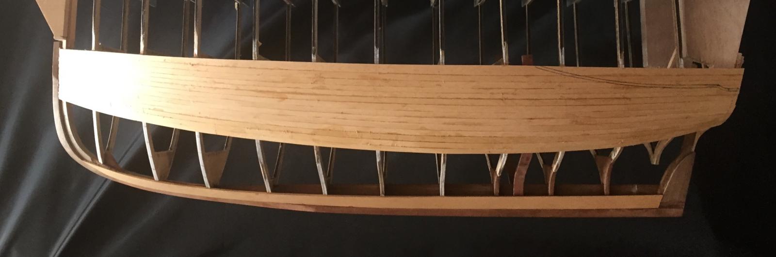
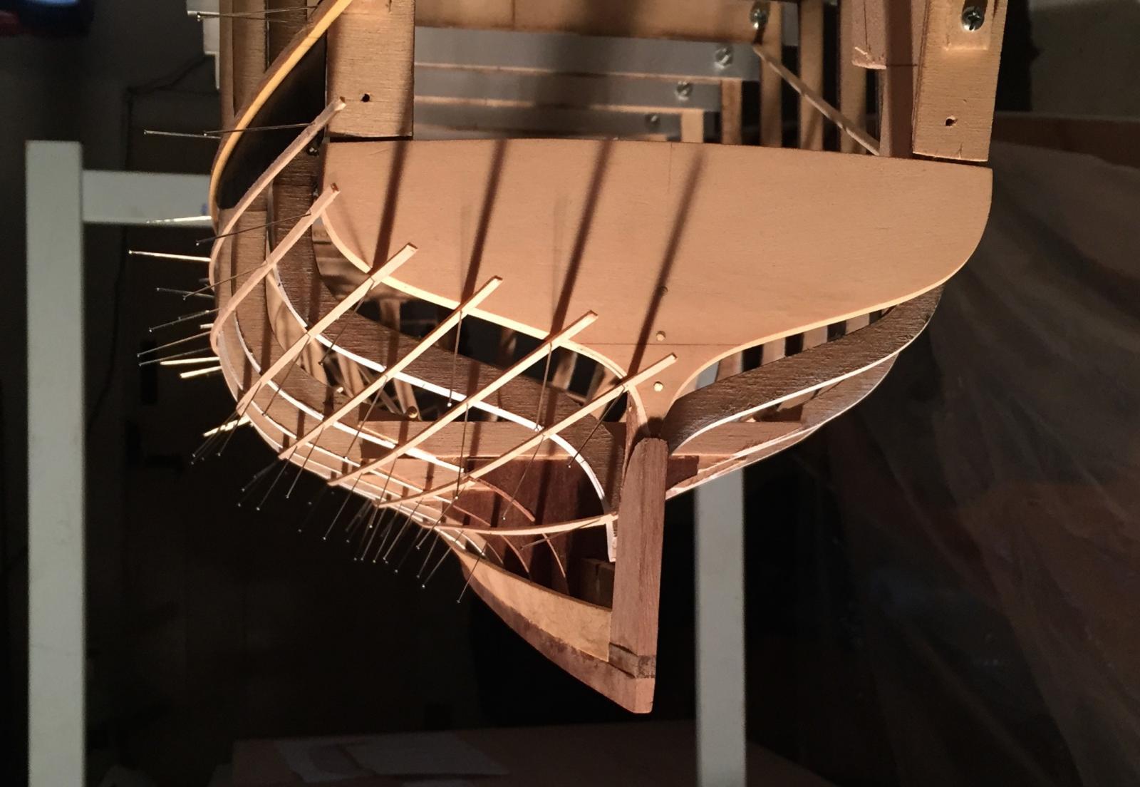
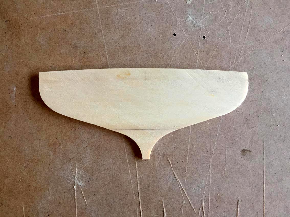
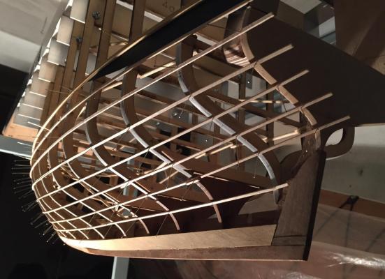
The garboard plank is on, & I can now set out the rest of the planking. To set out the garboard I used the example of the 24' Ranger garboard plank, which goes forward about as far as the forefoot. The reference The notches are to take ribs, the rib spacing won't be to scale, my estimate of enough to help hold the hull together.


- 411 replies
-
- 12
-
-
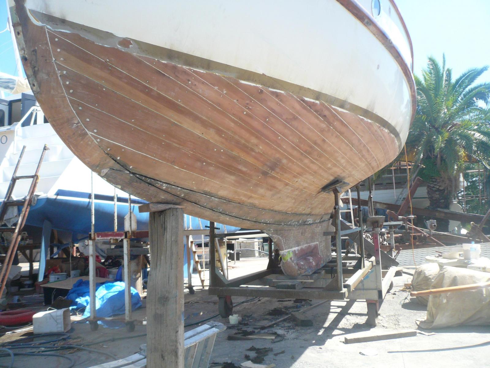
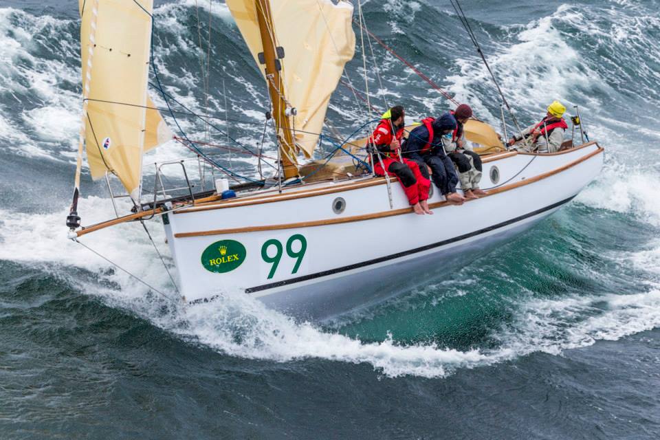
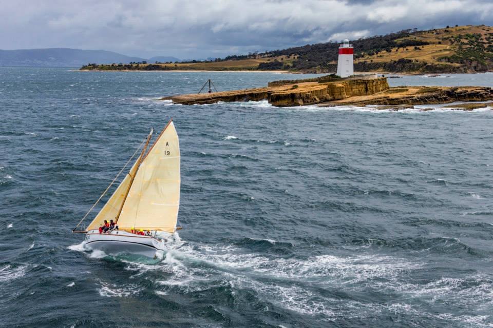
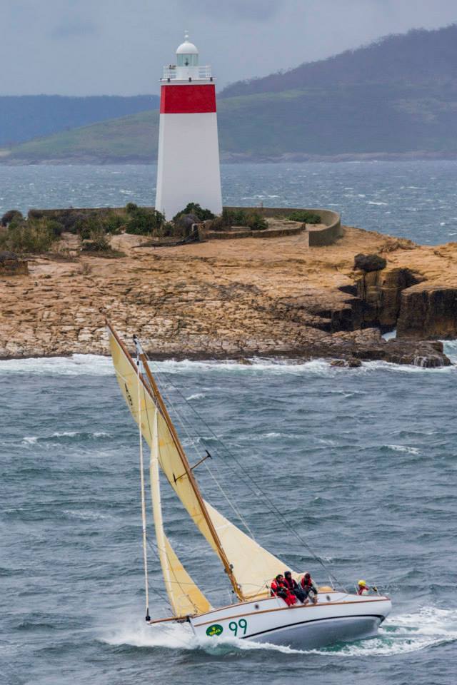
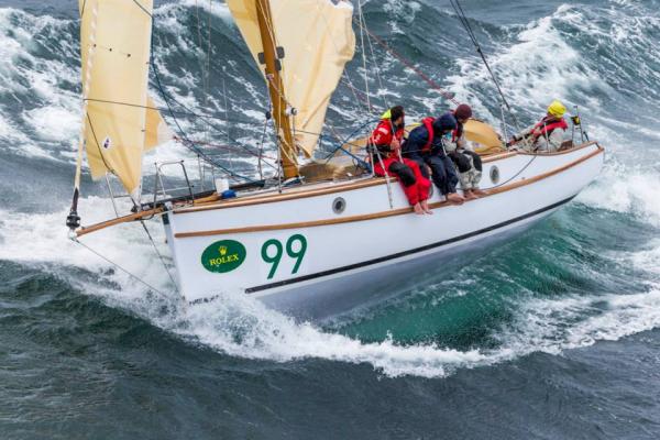
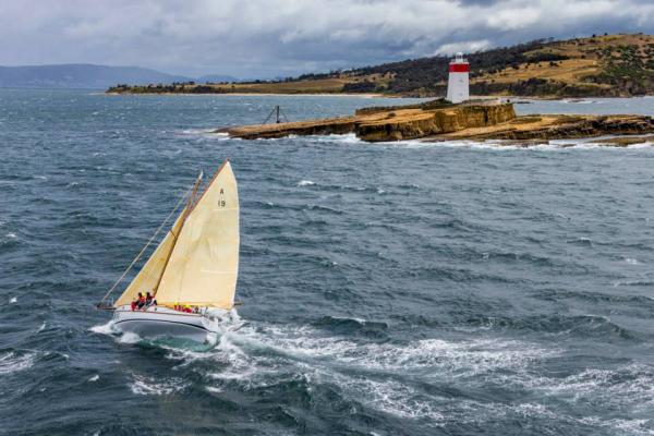
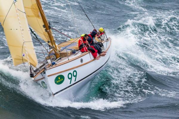
some photos of a similar yacht to the one I'm building, designed also by Cliff Gale : Maluka, photos from the last Sydney-Hobart, seen here on a close reach in 25-30 knots rounding the Iron Pot entering the River Derwent at Hobart nice footwear, too

- 411 replies
-
- 13
-
-
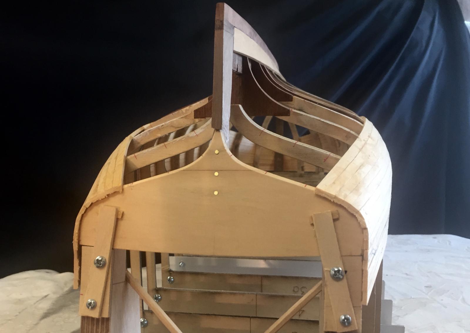
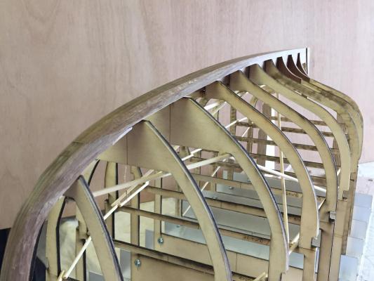
I am currently fairing the moulds & anything else that needs it - work now to be easier later hopefully. The shape of the temporary plywood transom was ok - so I cut the actual transom from the 3mm Huon Pine. In this photo it still needs to be faired, so the will be a bit finer again. Also, you can see slight asymmetry, the fairing & planking will reshape it enough that I don't need to worry about that now. To me, the transom shape of a boat is absolutely crucial to a good looking boat - like the final chords in a piece of music - & it's good to see that this one is looking right for this boat. The shape is soft & gentle, but with the suggestion of the amount of volume that the hull will have - she is a day boat designed to carry reasonable loads, not a racing yacht. The transom was pinned & glued. thanks for the interest, MP


-
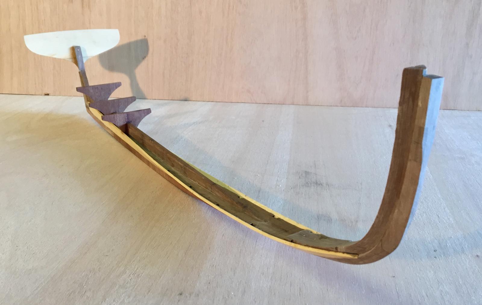
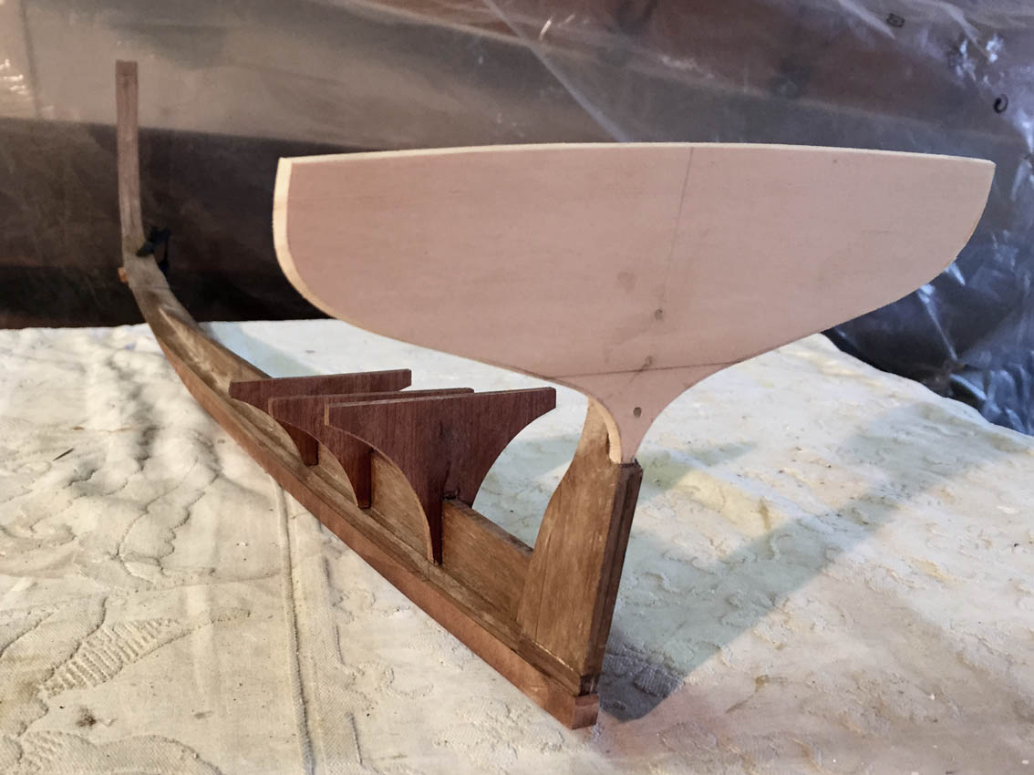
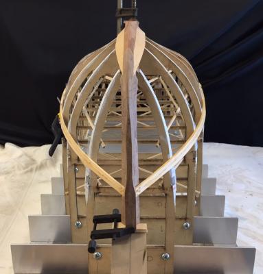
goodness how time flies... Well I have done some more this week: final fairing of the keelson & inner stem; making the outer stem & the strip below the keelson. I have separated the stem & keel into parts at the planking rebate line, & I'm now making the outer pieces. The keel piece will be screwed & glued to the keelson, & I put some of the screw holes right on top of previous brass pins, so I had to do some new ones - but I'll justify the extra holes by using them to pin down into the keel. I will need to pin the outer stem, for the same reason, that I'm always concerned that the pieces stay exactly where they are supposed to be during glueing. Also, these pieces have some twists etc that need to be taken out & the screws & pins help to remove the twist. The keel piece is Queensland Maple, really nice quality timber from bunk support pieces from our boat. The timber is nice, fairly light but still quite resistant to dents. It curved quite well too, I used a heat gun to put some curve into it, so that I doesn't want to pull the existing structure up & out of shape. I have shaped the underside edges of these strips to be perpendicular to the planking. The scarfed joints between the pieces are not sound in themselves, but are more or less the correct joint scaled up - the actual stem forefoot piece would have been a grown Tea Tree (Melaleuca) knee piece, but there is no issue with strength here & it will be painted so I'm not going to try & replicate the curved knee in this case. thanks, more soon I hope, MP


- 411 replies
-
- 11
-
-
Hello Mike Well done, she is looking amazing; I am enjoying this & learning a lot. Archer was remarkable & is a hero of mine. MP
-
Hello Jim, lovely. Really enjoyable to look at. I was in Pittwater a few weekends ago & there is a boat in Careel Bay that looked very much like a Pearling Lugger, I would guess that the hull was 42 or so feet. Do you know of this boat? Sorry, if I had any wits I would have taken a photo. Mark
- 745 replies
-
- 1
-
-
- francis pritt
- mission ship
- (and 1 more)
-
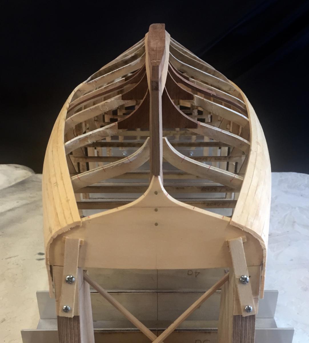
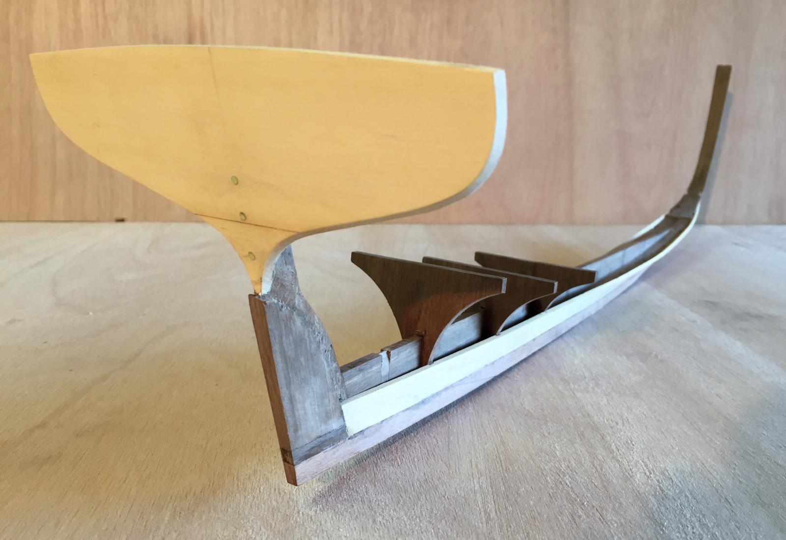
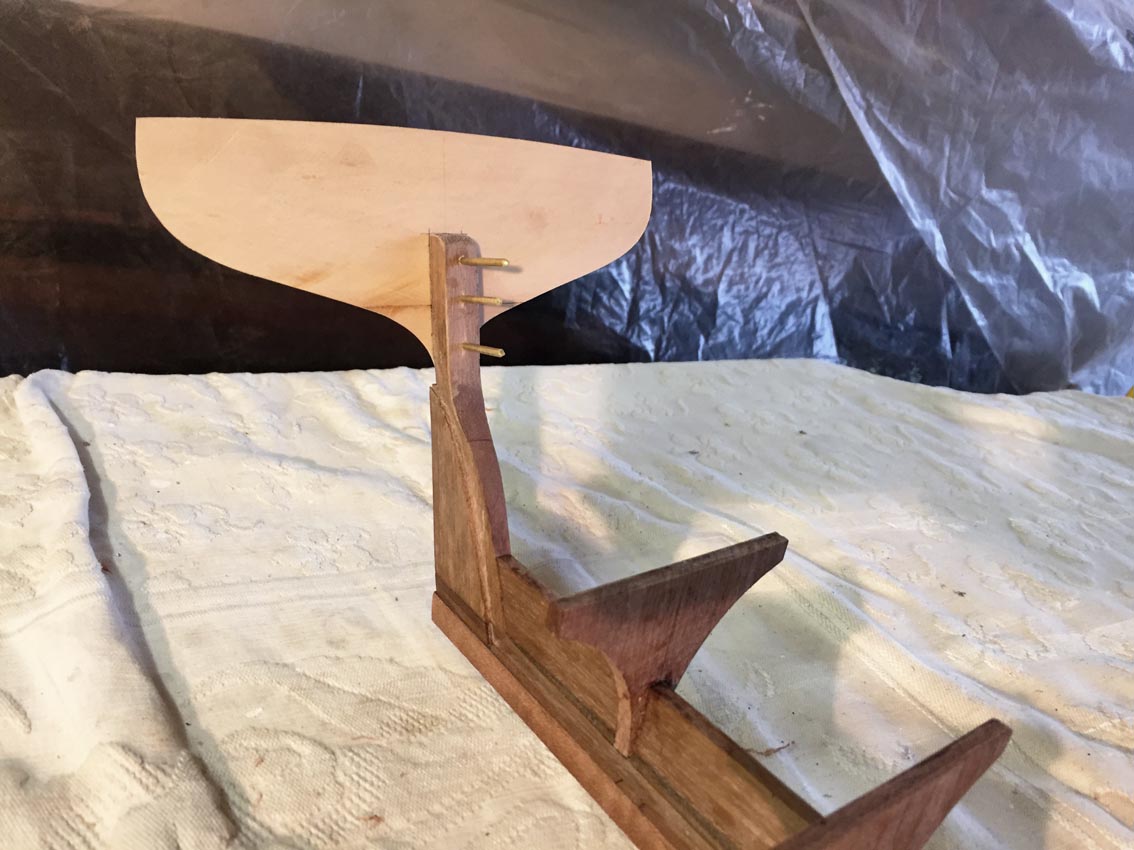
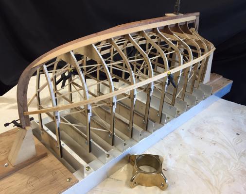
I've done a bit more: the solid lower bulkheads aft have been cut & glued in, & the inner part of the keel has been faired. I'm satisfied that these solid pieces will help, perhaps if I'd planked a model boat before I would know if this shape would work without them or not, but for a small amount of work I'm making it a bit easier to get that important part right. To me, the most important part of the hull shape in these boats is the water exit lines. It's not an accurate scale version of the way the hull would be constructed, but the main objective is to end up with the right hull shape externally. Internally, if I'm happy with the logic, that's enough. The solid bulkheads still need to be stabilised so that they stay in the same plane as their plywood bulkheads during the fairing process, & yet are able to be separated - for when I remove the ply later. Next steps are: - checking the temporary transom, & fitting pieces to stabilise it also for the fairing process. - glue in more bamboo skewers generally, the brace the moulds & hold them rigidly in place - temporary pin for the inner stem, same reason Then I can fair the hull. I might also do a profile of the outer face of the stem & inner keel, I could do a fairly accurate template now while it's still removable. This would give the inner shape of the keel & outer stem for later. In the photos, the inner keel is sitting up a bit - it does actually sit down flush on to the tops of the stations. As an aside: I asked a boatbuilding friend about the piece I'd been calling a stern knee - he says this is the correct term. But he also said that my use of keelson isn't correct, there is such a thing, but apparently it sits above the ribs. So I'll call it "inner keel" for the same reason I call the stem piece the "inner stem", for practical model making reasons I've separated the stem & keel into pieces, divided along the rabbet line. thanks, until next time

- 411 replies
-
- 12
-