Mark Pearse
-
Posts
840 -
Joined
-
Last visited
Content Type
Profiles
Forums
Gallery
Events
Everything posted by Mark Pearse
-
 a possible additional reason for the central sheeting of the mainsail is that with such a huge & powerful sail, the third restraint would reduce the load on each by spreading the same load between three points instead of two. Maybe you can also control the sail more easily as well.
 -
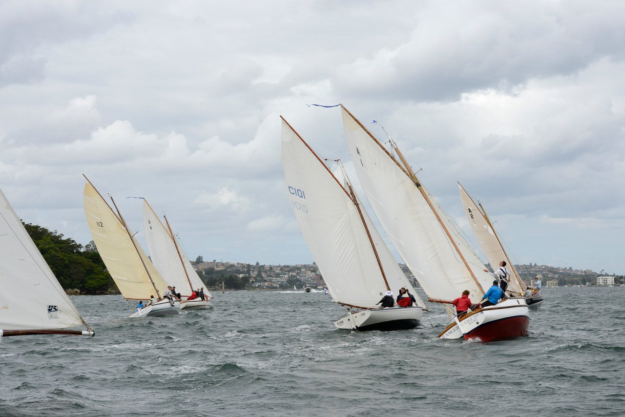
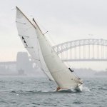
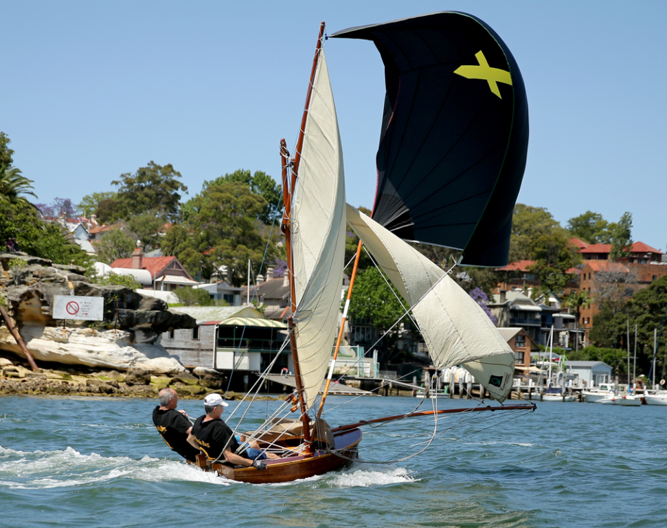
Hi Dick Amazing work, & the sails are beautifully done. I'm not familiar with these vessels but I have some sailing experience. The lateen sails on these pictures are very different in size, it looks to me that the larger stern sail in the painting would screen the main sail but also tend to make steering the vessel more difficult because it's large - the relationship between the sails looks different in the ink drawing. Regarding the general use of these sails, I would think that if you were entering a harbour, you would most definitely have the stern sail up, as that sail in particular would give you the ability to round up into the breeze to slow down or stop. On a different note, the mainsail shape is very interesting, they have a huge upwards billow that doesn't really increase the forwards thrust much - it's possible that the upward billow on the mainsail is intentional to help counteract the tendency of the bows to bury into the water, which would make the boat harder to steer & slower. Why they might need to do this I'm not sure, but the hull shape doesn't look to have as much forwards buoyancy as your more classic square rigged vessel, the buoyancy would counteract the downwards effect. An unrelated example might be helpful to see this - in early Sydney skiffs their spinnakers were set in a way partly to give lift & keep the bows up downwind - the situation is very different, but the size of the billow itself doesn't add power, but it changes the direction of the thrust. See below, a 6 foot skiff (copy of a type from early 1900s) - very very different, but maybe there's a connection....in the photo it's really easy to see how they are trying to stop the downwards effect on the bows. Mark
-
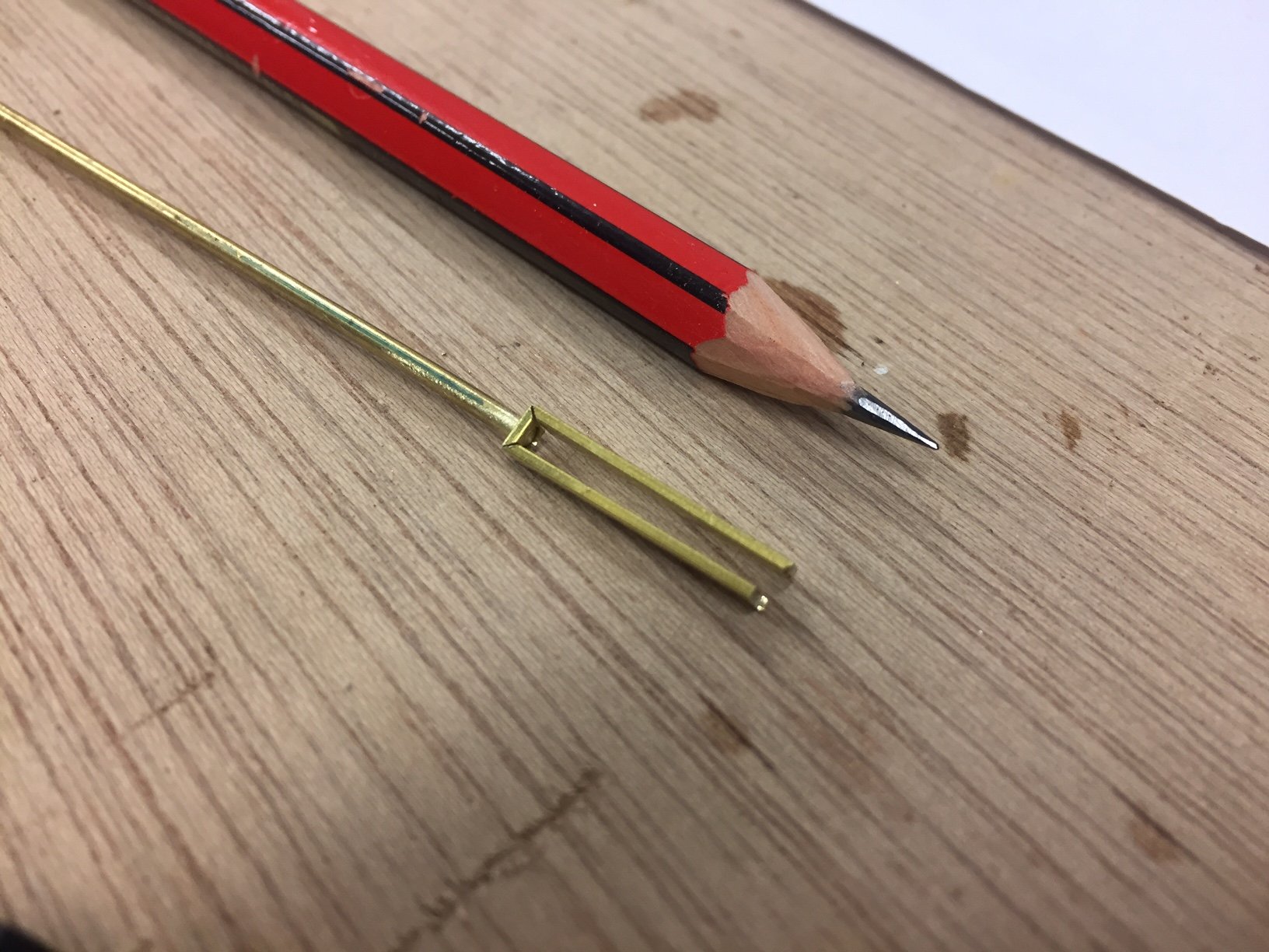
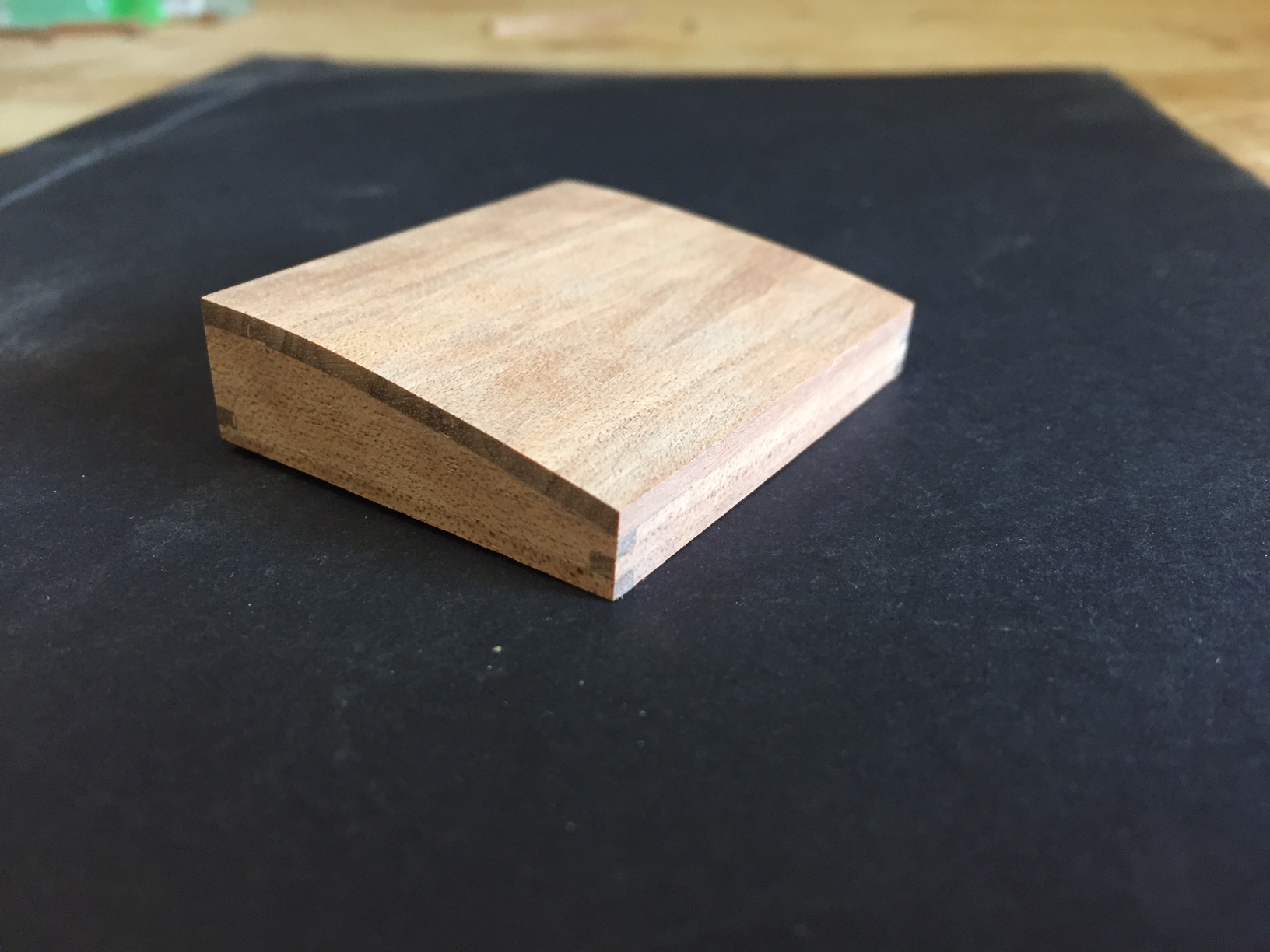
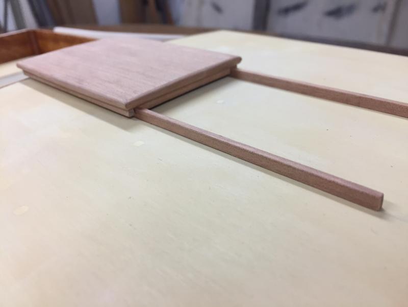
thanks all. Hi John, yes I love looking at photos of gaff rigged boats also. Hi Michael, I drilled the holes after brazing - to be sure that a pin will be able to slide through both holes smoothly. I sized the gap between the tangs to match the standard brass size of 1/16th", so that I could clamp a small piece of that size between the tangs when brazing & then drilling. The other part of the assembly, that goes onto the rudder & fits into this part (name?), will be from 1/32nd" flat bar so there's also a small amount of play - as there would be in real life. My metalwork equipment is pretty low-tech, I used one of those small one-hand drill holders for the holes because of the risks of using a standard hand held electric drill being too powerful. Also, I could adjust the location of the drill in the initial stages a small amount, get it more centred by angling it until the hole reached its full size & was then set in location. Mark
-
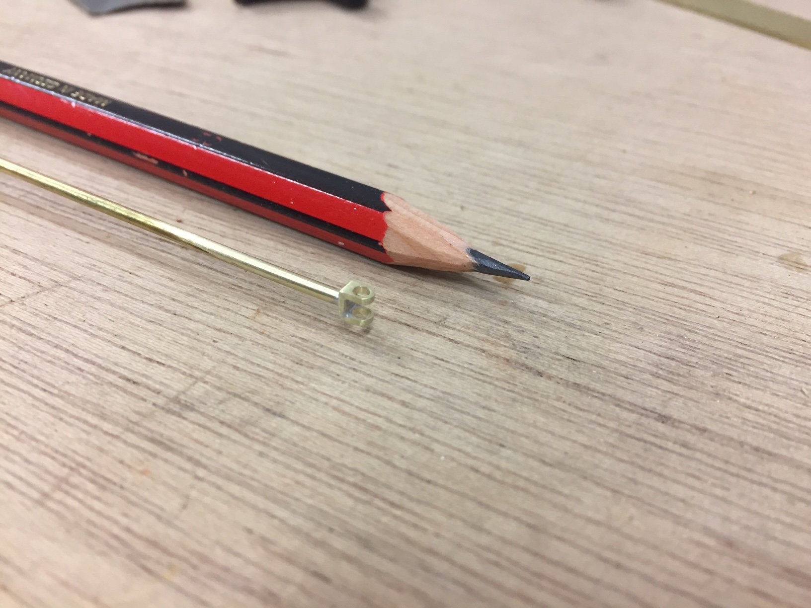
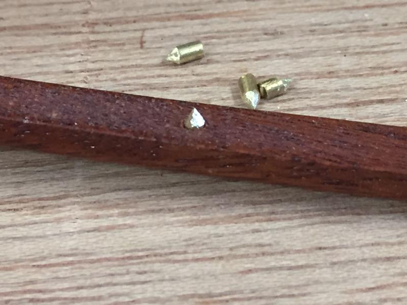
Hi everyone it's been a long break from the model, but been consoling myself plenty of this anyway: I'm starting on the metalwork details & previous efforts showed that I really to need to plan so that the pieces can be held, they are really small & I'm not used to that. So, I'm trying to make sure I ca hold them in some way. I've started on the top rudder gudgeon & pintle assembly, below is the gudgeon started. My method is v-cuts in the brass bar & then fold & solder it. The gudgeon will have a hidden rod into the transom for fixing. Below is the parts folded & the rear pin fitted. Below is after brazing & shaping. thanks, Mark


- 411 replies
-
- 10
-

-
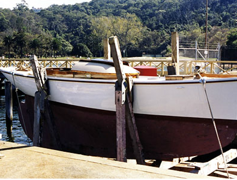
Hi a beautiful craft & a really beautiful model. Thanks for sharing the pics. Amazing combination of beam & fine water entry, pity there's none sailing. Mark
-
Hi Vaddoc your question about removing the model from the base is tricky but you have more room to do something now than later. One idea is to drill now a series of holes through each mould, at the line where you will cut later. The small piece between adjacent holes will be cuttable with in a series of short cuts, & maybe even with a knife. best of luck, Mark
-
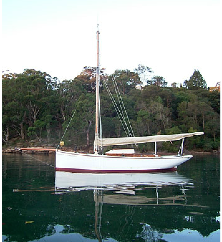
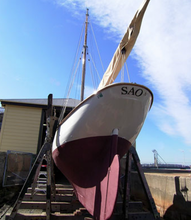
HI Martin a lovely yacht & model. Does she come from a working boat background? The lines are amazing & very beautiful. There aren't many yachts here in Australia with lines like that, but for your interest I attached the photos one unusual yacht, built 1905. Like a miniature version of your lovely Vanity, or something similar. A 22' gaff topsail cutter based on a pilot boat lines. good luck with the build, please keep posting Mark

-
Hi Vaddoc I also did my first plank as the garboard plank, I hadn't done any planing at all before that. At the time I asked a shipwright about the shaping of a garboard plank, & he said that in a full keel boat the maximum width of the plank would usually be used at the stern end, then tapered to the bow, the amount of taper depending on the hull shape. That seems to be what you have done. best of luck with the rest
-
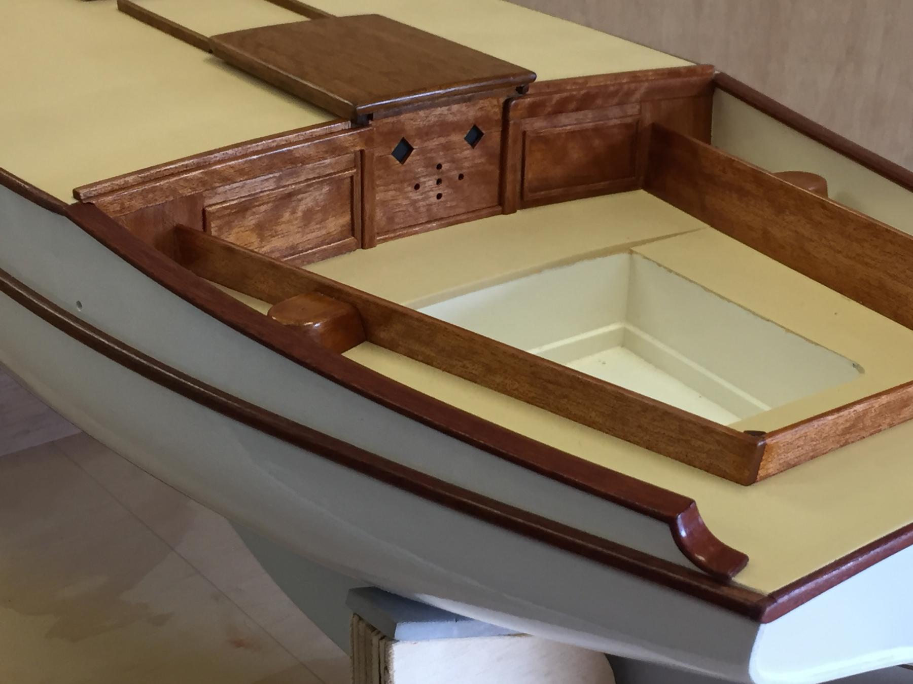
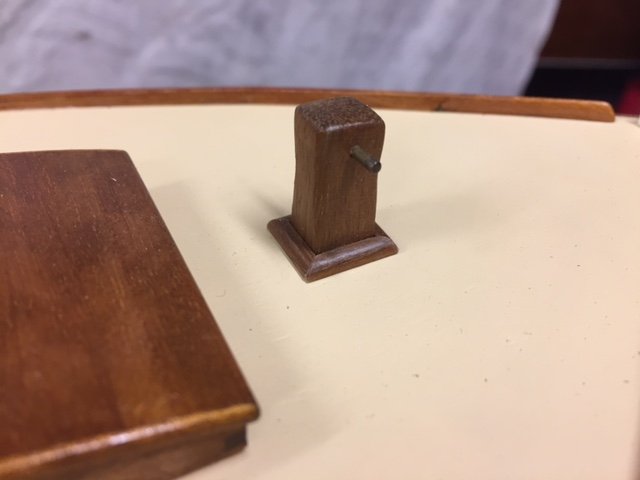
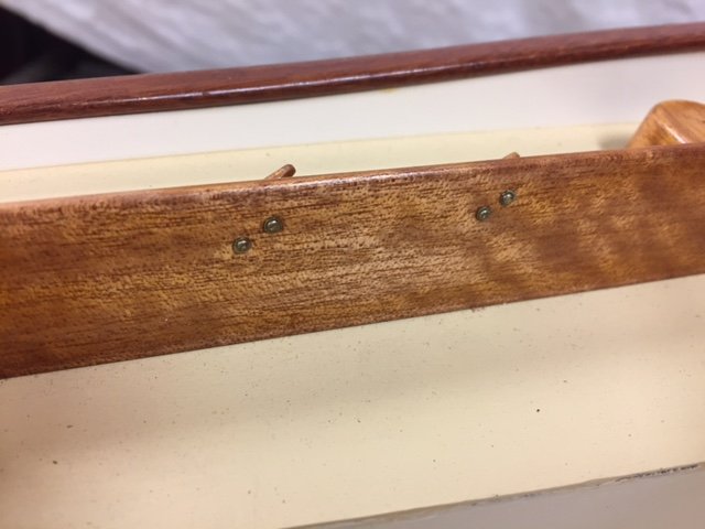
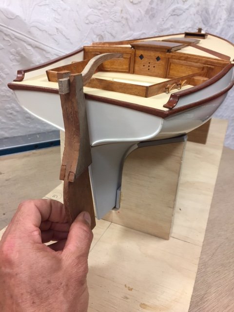
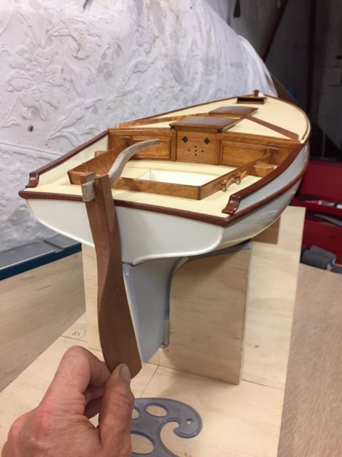
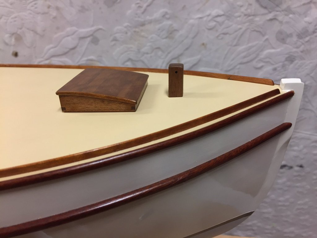
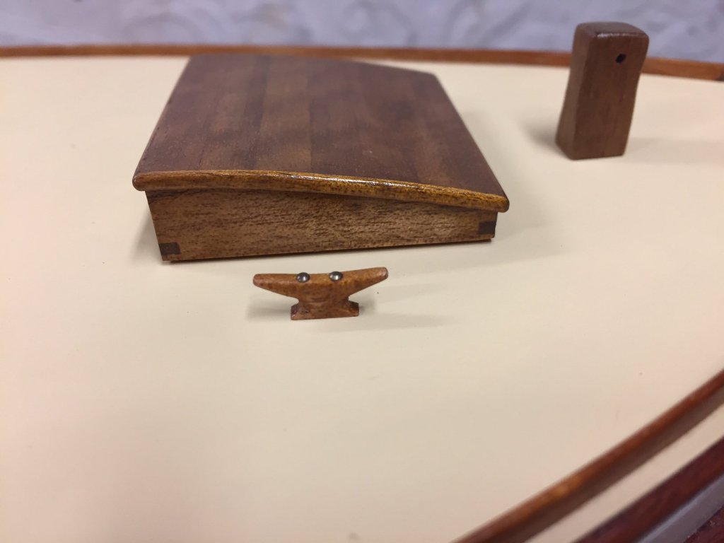
many thanks, John Patrick & Pete, plus the visitors The sampson post has been trimmed the cockpit area horn cleats were made & installed, the rivets were replicated with small brass nails, & I made some washers from brass rod & drilled the centre out; the cockpit coaming ones are maybe on a bit too much of an angle the rudder & tiller are underway, roughed up, & shaped as below thanks, MP

- 411 replies
-
- 17
-
-
Hi Michael - what's the technique fro drilling acrylic sheet without cracking it? Mark
-
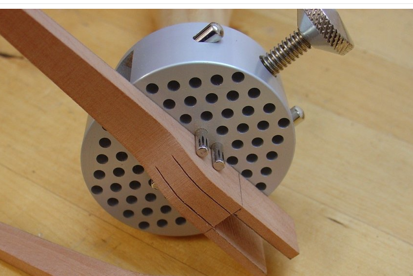
Hello Alex, very enjoyable, & beautiful. Is this tool some sort of clamp? thanks, Mark
-
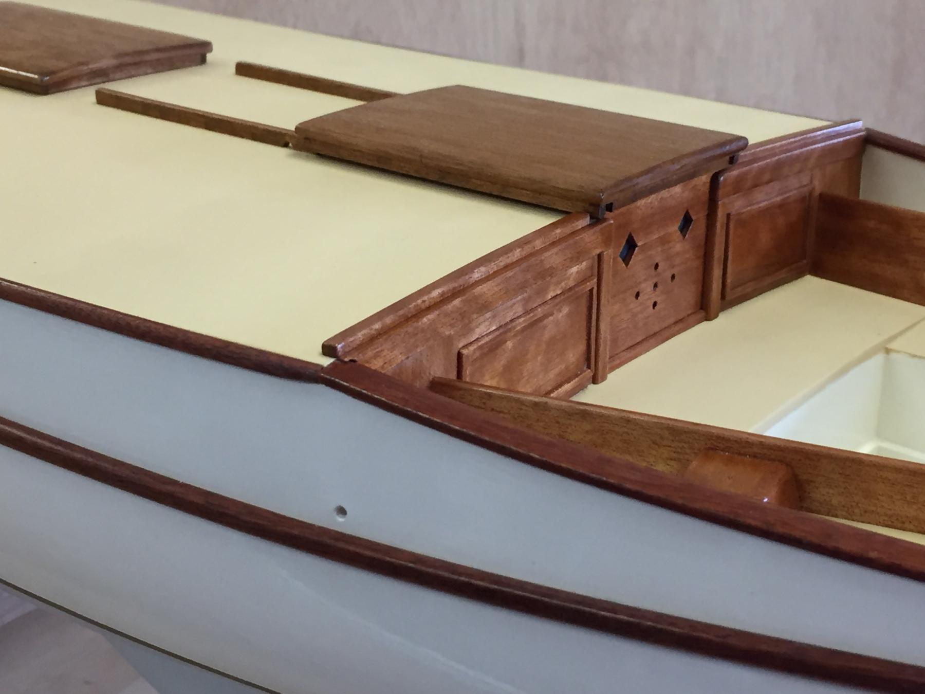
A bit more....the toe rails are done & installed & I'm making the 6 horn cleats that sit around the cockpit area. The toe rails seemed especially fragile & gave me some grief. The Queensland Maple generally seems good to work with, but 1.5 x 2.5mm seems to be beyond it, just seemed to break at the slightest touch. Sampson post started also, it will need a rod plus some quad timbers to trim it off. thanks, MP


- 411 replies
-
- 18
-
-
Hi Patrick, a very interesting project & enjoyable to watch. thanks & best wishes, Mark Pearse
-
beautiful John. The stern shape is beautiful & looks unusual to my eye: is the design typical for these boats, & for a particular reason? thanks, Mark
- 745 replies
-
- 2
-
-
- francis pritt
- mission ship
- (and 1 more)
-
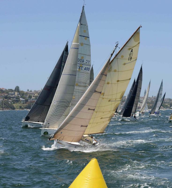
thank you As a comparison, this shows the most similar yacht, Maluka, fully powered up just after the start of last Sydney Hobart, sporting an immaculate sails set beautifully.....drool. You can see the canvas spray dodger.
-
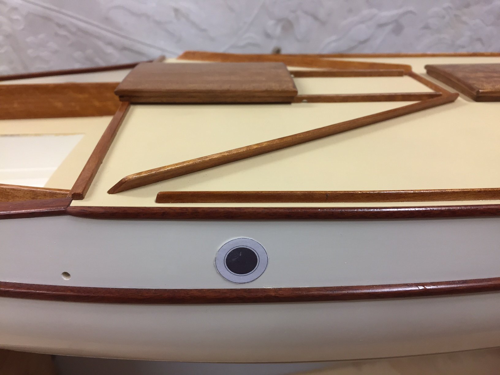
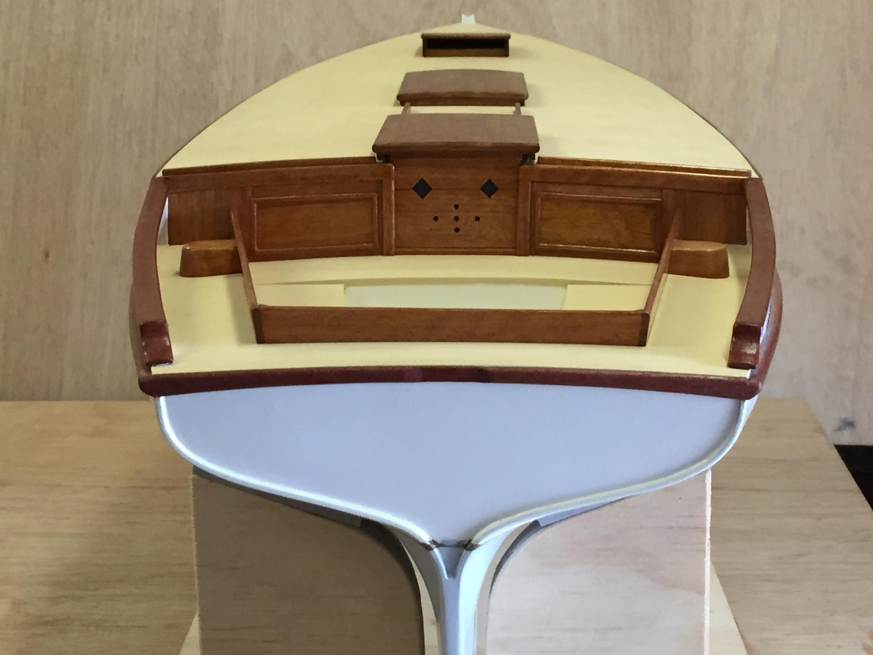
thank you Patrick, & I agree that the designer had an artistic eye - The spray boards are on (not sure if they have a proper name), they channel spray across the deck & help stop it going down the companionway hatch, & a spray dodger would clip off to it. The toe rails will possibly be next. Also, temporary portholes / scuttles, done with paper to check position & size. thanks


- 411 replies
-
- 10
-
-
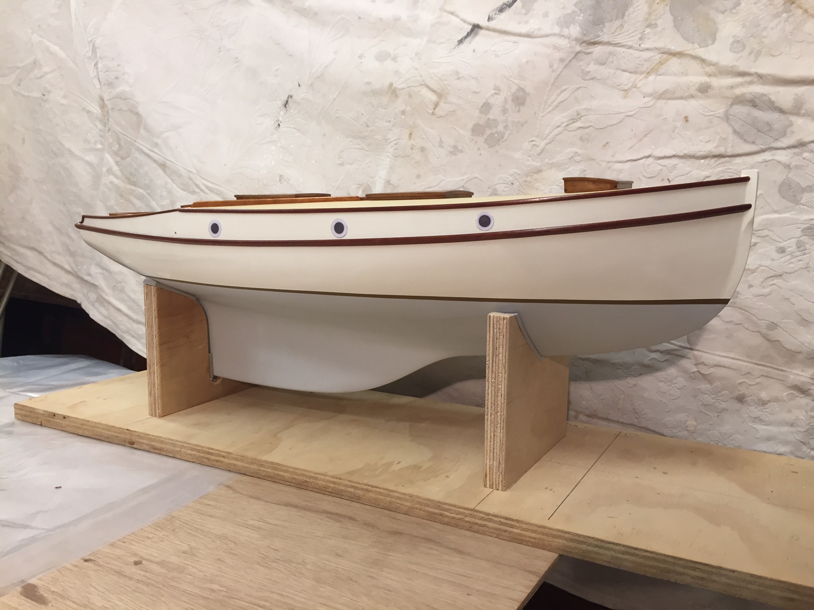
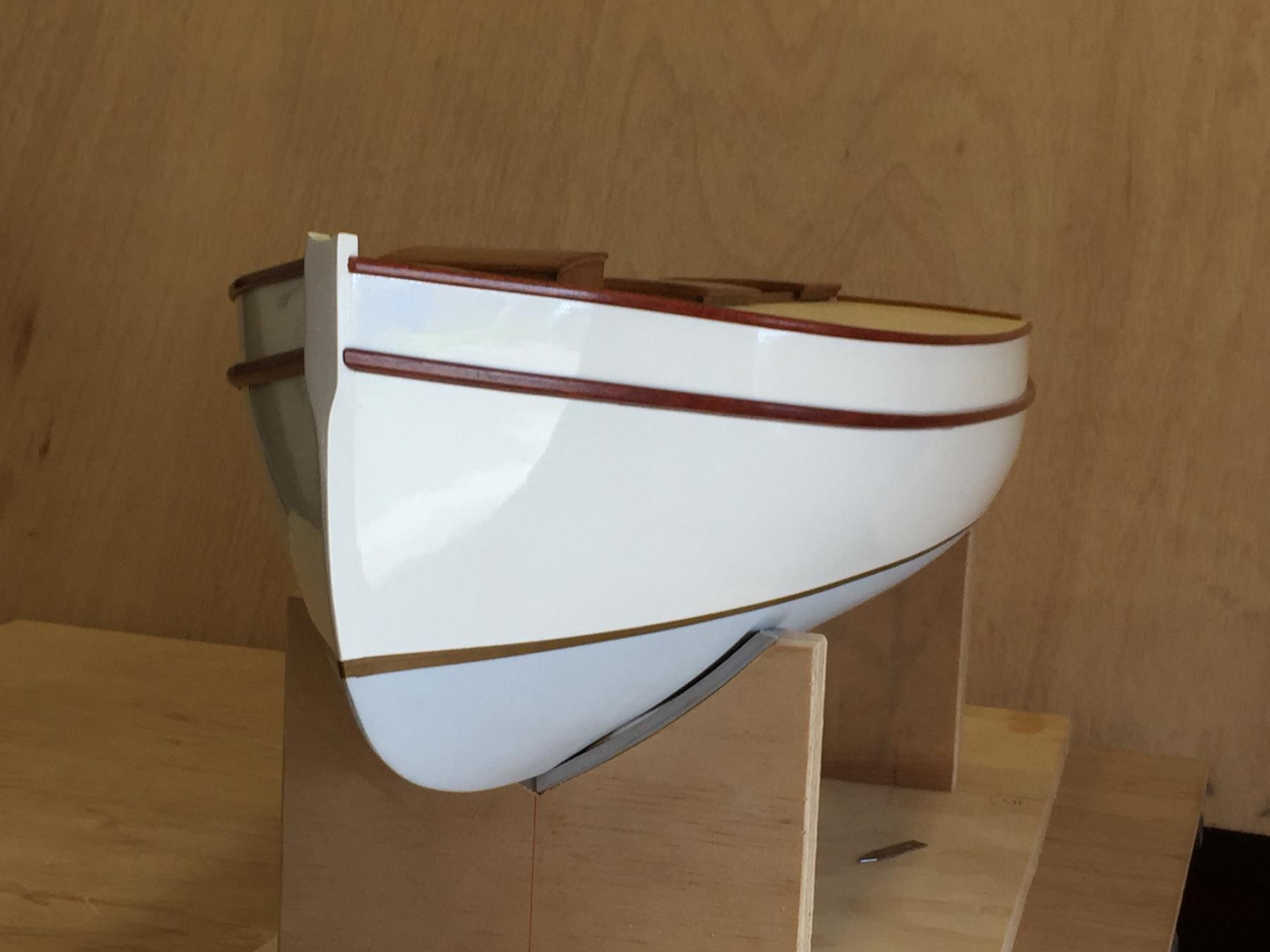
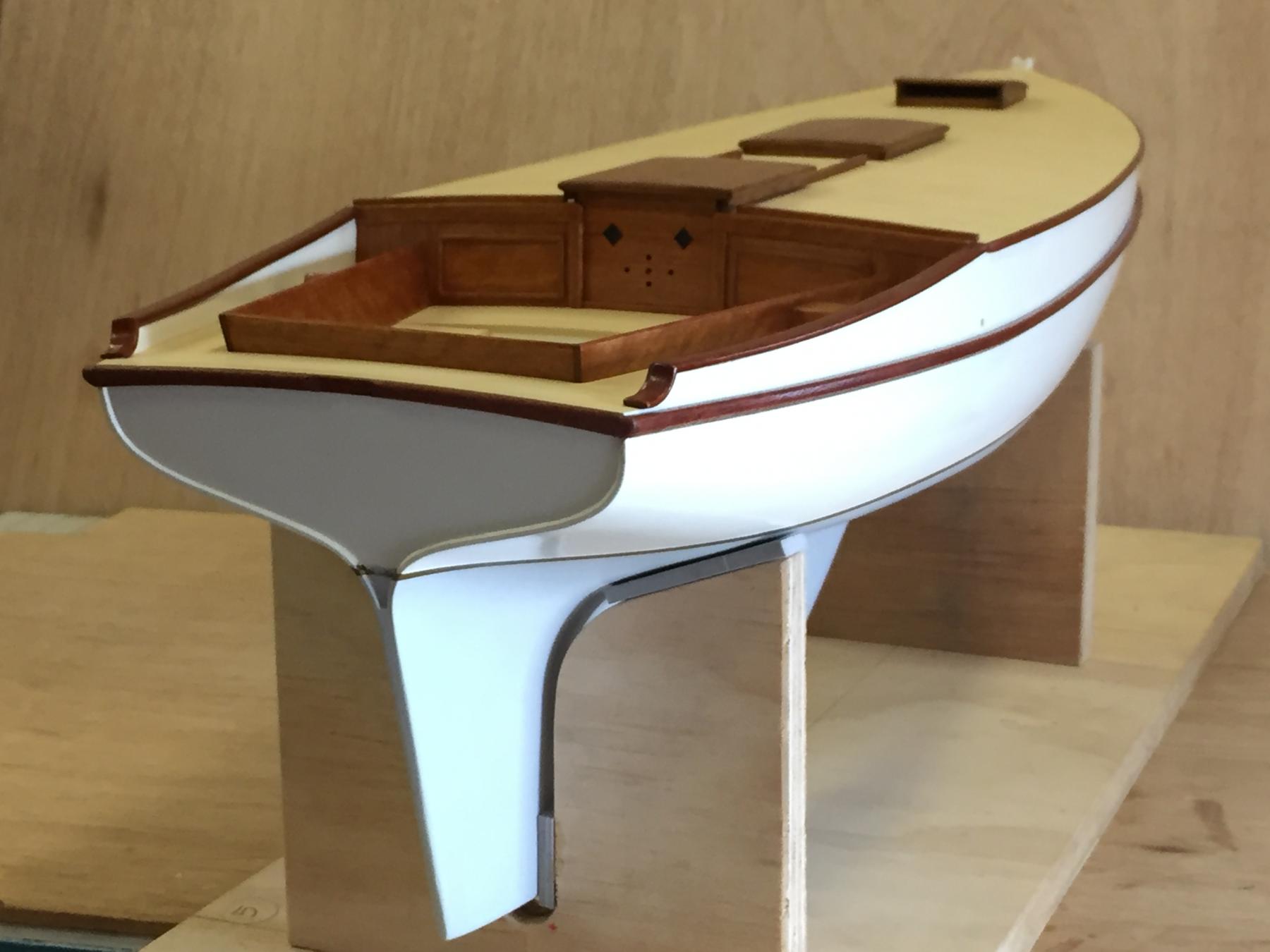
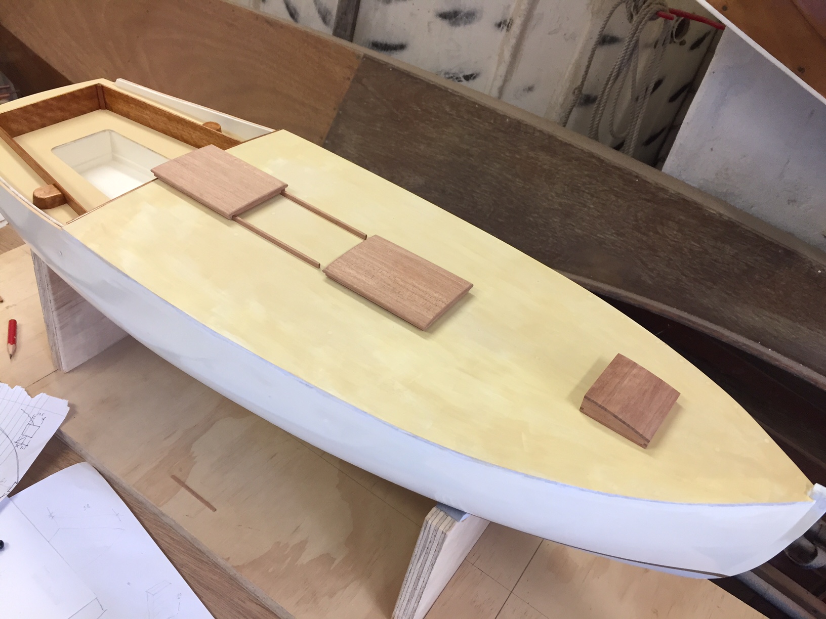
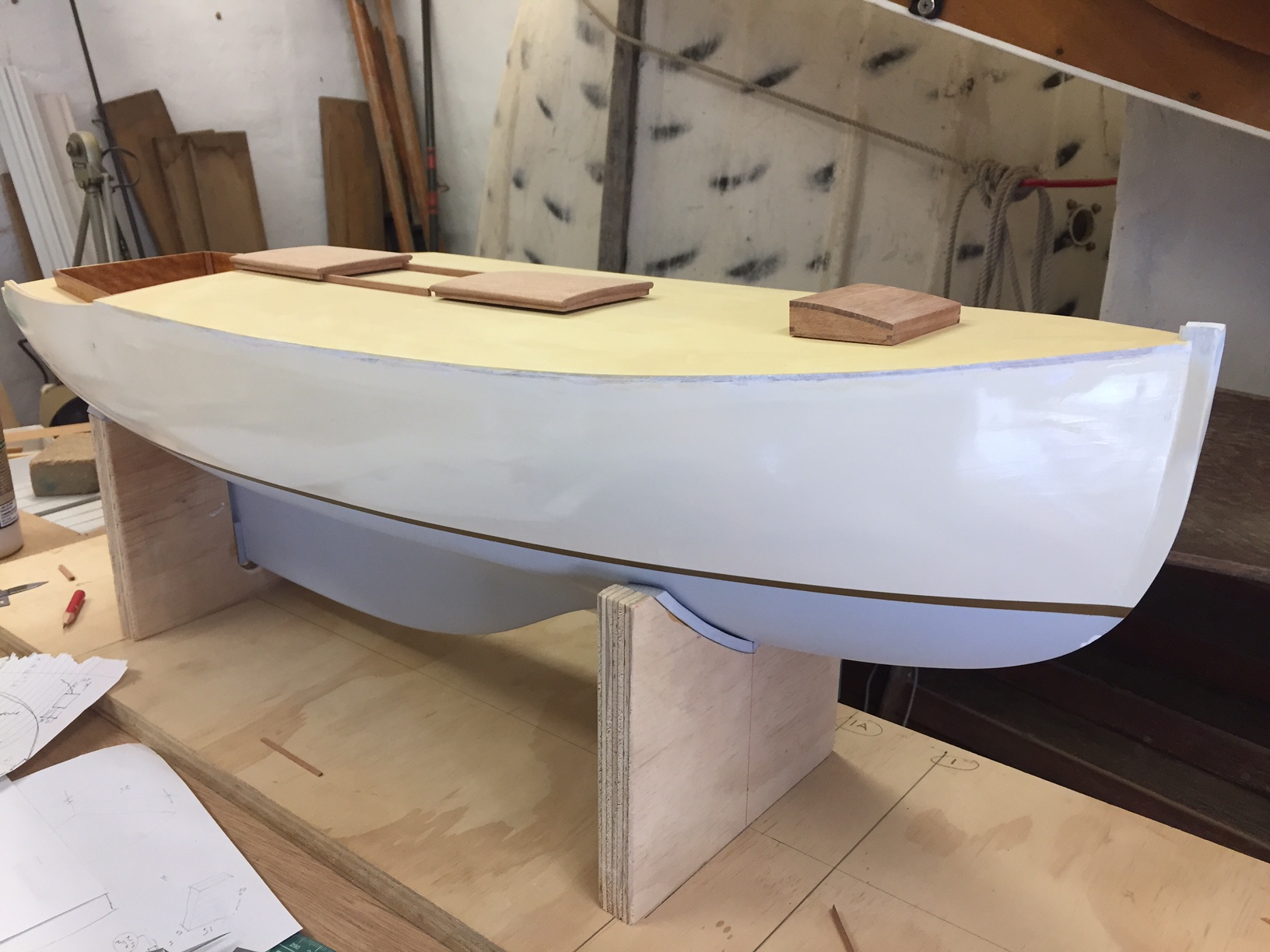
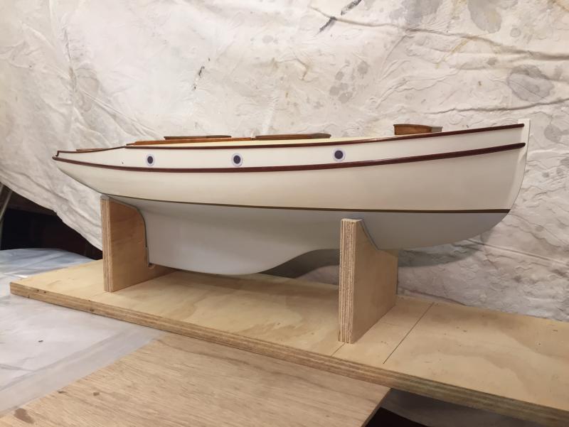
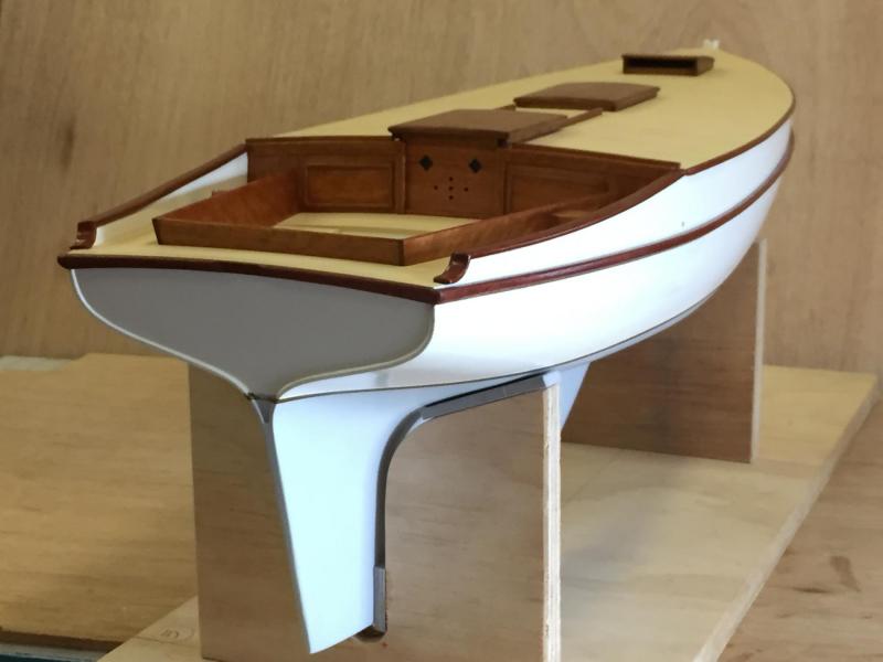
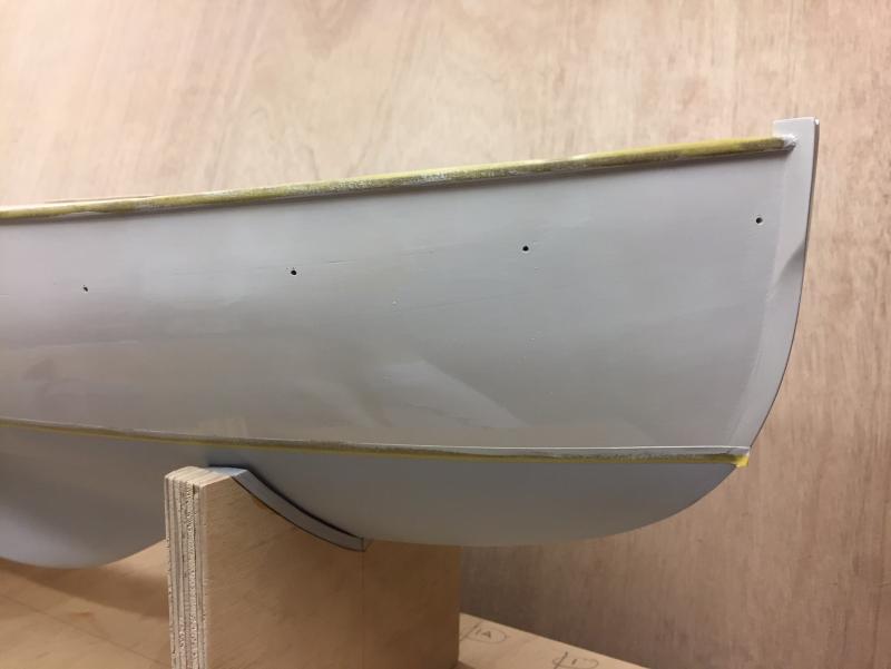
The sponson have been glued on, plus the transom fashion piece that completes the timberwork of the sponsons around the stern. The hatches also located, there's some more deck timberwork - some spray rails, toe rails etc, Looking like a boat now. thanks, Mark


- 411 replies
-
- 15
-
-
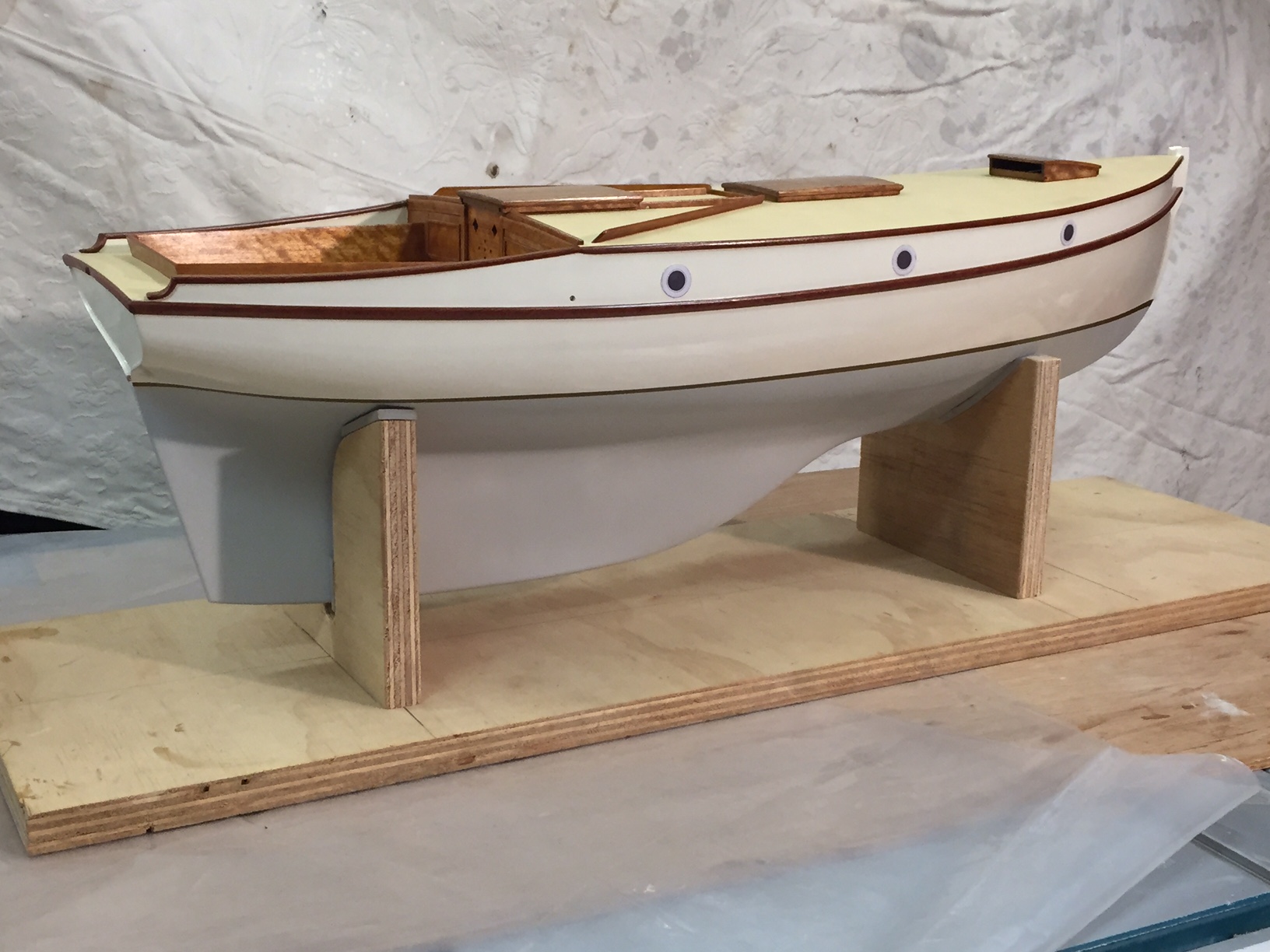
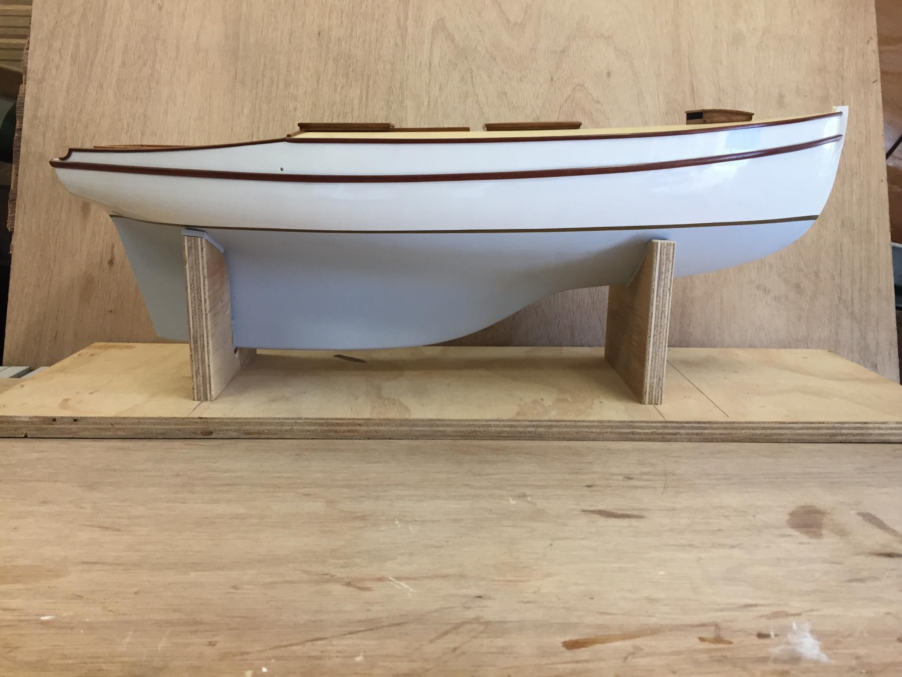
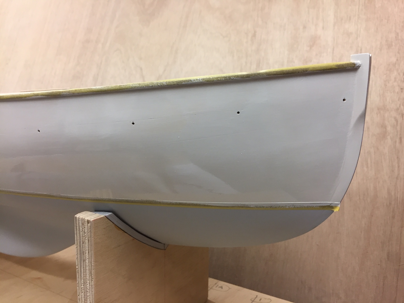
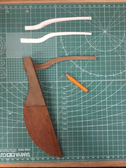
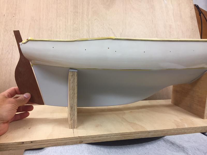
Back to the work bench again, lots of boating fun over summer... I've started the rudder blade, as below. My understanding is that the designer put a sloping transom on this boat because he didn't like the fine edge of the rudder blade getting damaged by a dinghy, so the concave part of the curve near to the waterline might be altered to fulfil this intention. The careful work of setting out the sponsons is underway; it's possibly the most challenging visual thing to get right on the design; the gunwales line give one curve, & the sponson line is in balance with that. The setout was done by wrapping the hull in about 6 large rubber bands & sliding the sponson strips underneath the bands. When I was happy I put a pencil line on the hull topsides. To help with accurate installation, I made some small studs that temporarily sat in drilled holes in the back of the sponsor strips. The positions were marked by pressing against the hull; the studs were replaced with brass rod that will help hold the strips in a stable position while the glue goes off. studs drilled holes in hull, repainting underway sponsons with rods; also the 'teak' colour of the hatches went ok

- 411 replies
-
- 10
-
-
Hi John this has been great to watch, she is a beautiful & delicate model, & must have been a very pretty boat. Mark
- 745 replies
-
- 3
-
-
- francis pritt
- mission ship
- (and 1 more)
-
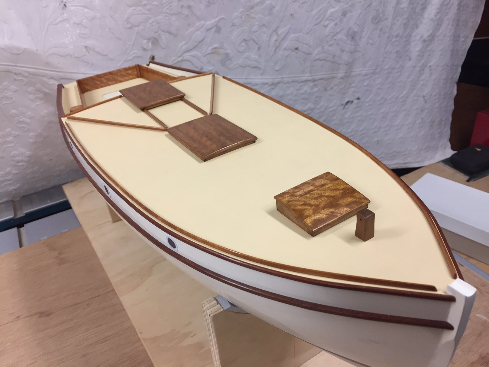
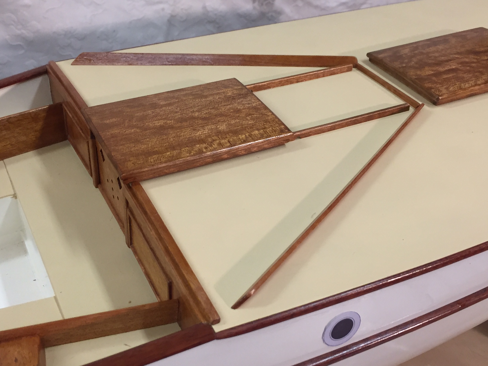
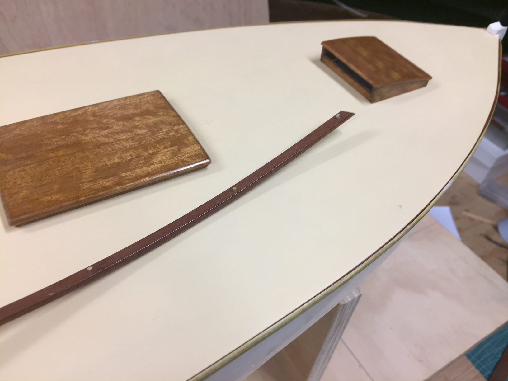
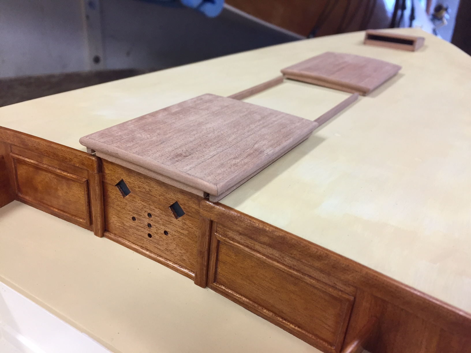
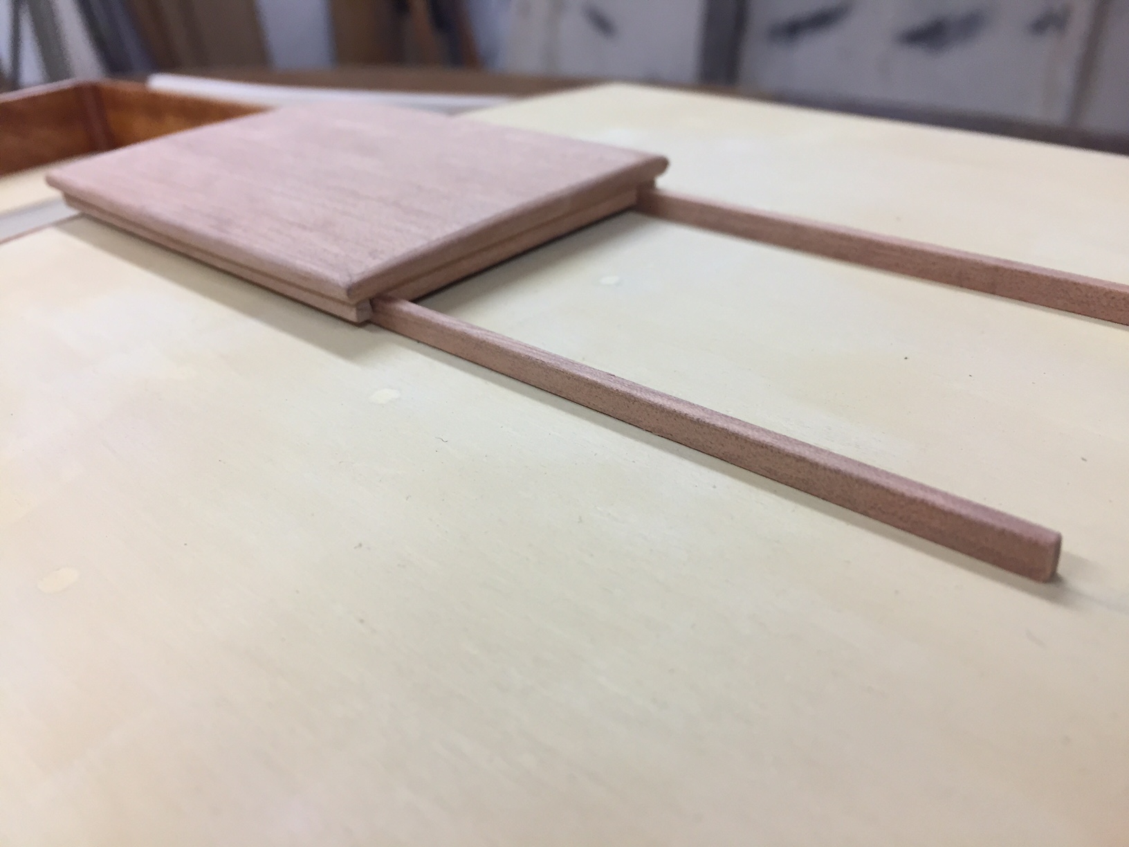
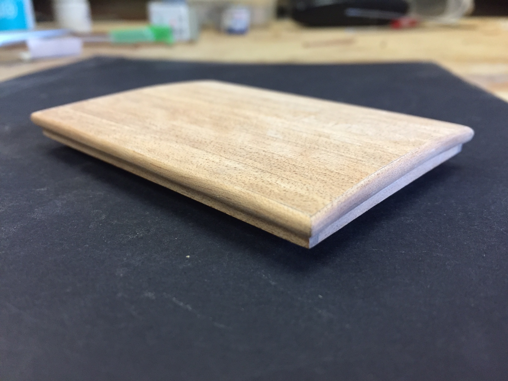
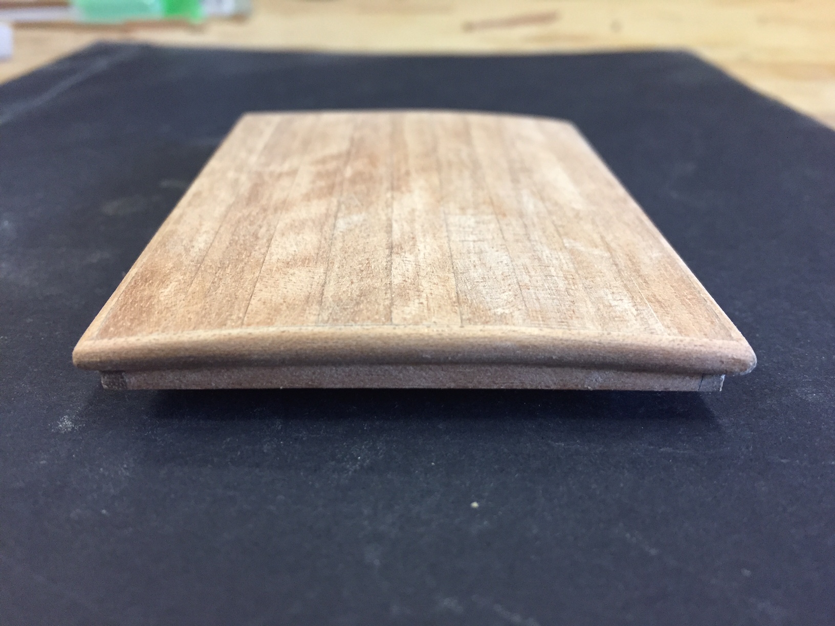
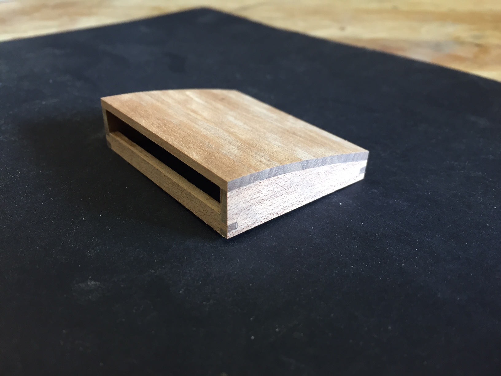
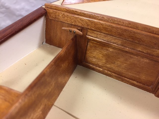
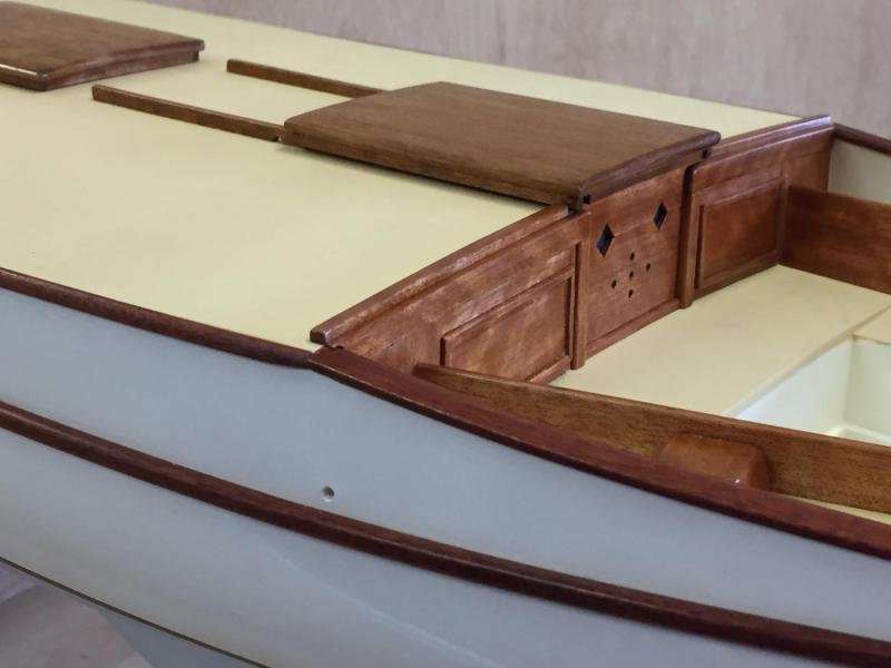
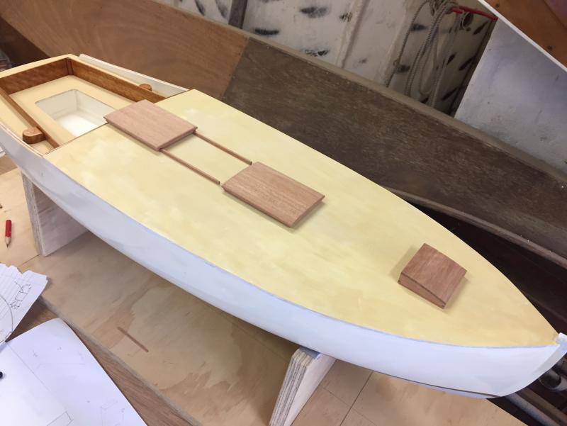
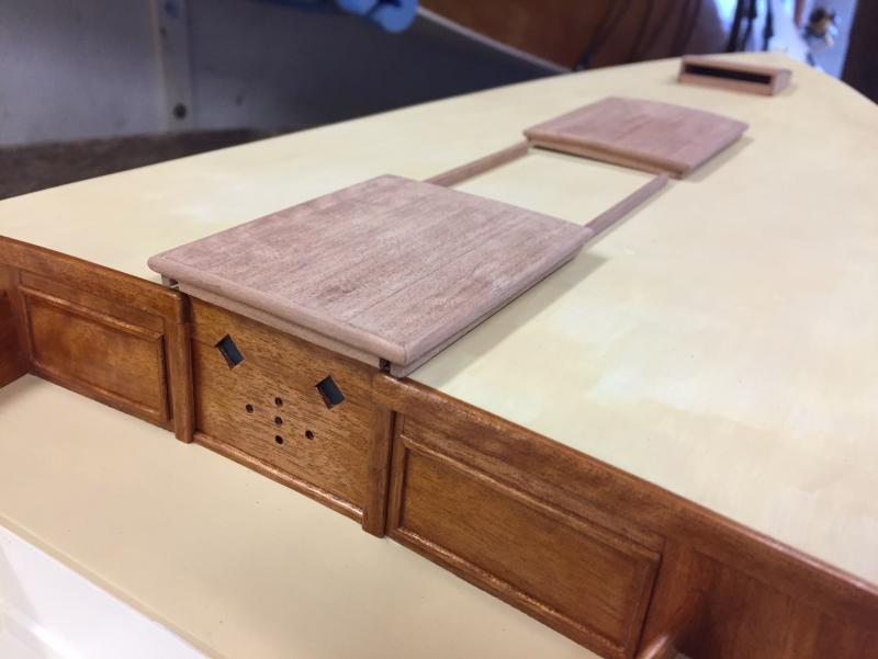
The hatches have progressed & are almost complete. They are just sitting in place & no finish as yet. I'd like to show a more teak colour than the other timber is, so I'll try putting a touch of black ink into the shellac - or perhaps a light watercolour wash on the timber before the shellac. The companionway hatch is a simplified version of a simple mechanism & not much detail is shown, it is intended to be a very simple system anyway, similar to some that I have seen. I may show a brass flat bar on the top of the timber rails, but my metalwork has yet to be tested so we'll have to see about that. The decision will partly depend on the balance of detail on the model - The curved beading at the ends was heated with a heat gun while I gently bent them with my fingers. A few cracked beads & lightly smoking fingertips, but when it worked they took only a few minutes. The timber is fairly brittle. The main hatch might get some lights set into it, I'll decide that later, but fixed round lights would be a nice touch. The fore hatch is ventilating, it's not quite completed, I will probably put a simple beading to the edge, similar to the others but probably a bit finer to suit the smaller size. The implied dovetails are just cut square & not bevelled, I felt that in this case showing some construction detail was important to give a sense of how the timberwork would be put together. thanks, good wishes for the Christmas season everyone.


-
Hi Vaddoc, your boat is looking very nice. I'm really new to this hobby, & one part of me is wary about giving advice when I'm not experienced, but it was from a friend that knows about boats & was useful for me at the same stage you are at - he said that if you can see the hull the right way up (i.e.: not upside down), & you can better judge how well the battens are lined off (assuming the battens are the future planking lines). It helped me; so I suppose that we are better at seeing a nice planking setout than we realise, we've all looked at a lot of photos & something must have sunk in. Mark