HOLIDAY DONATION DRIVE - SUPPORT MSW - DO YOUR PART TO KEEP THIS GREAT FORUM GOING! (Only 24 donations so far out of 49,000 members - C'mon guys!)
×

bensid54
-
Posts
531 -
Joined
-
Last visited
Content Type
Profiles
Forums
Gallery
Events
Everything posted by bensid54
-
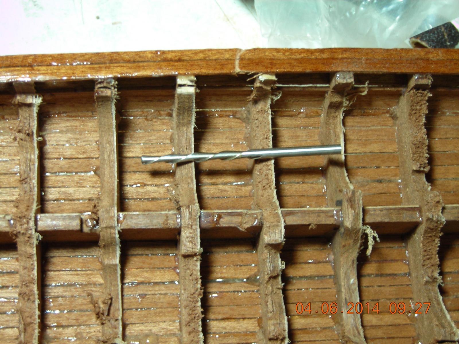
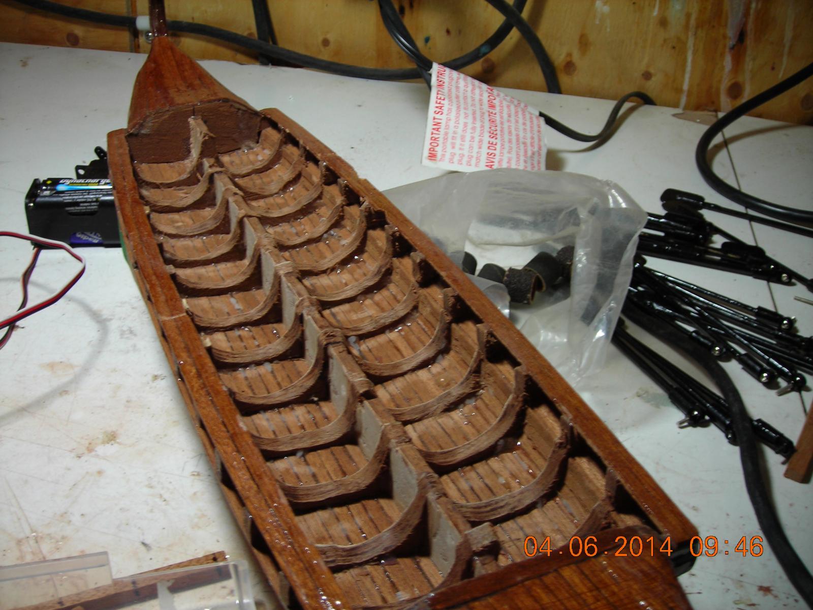
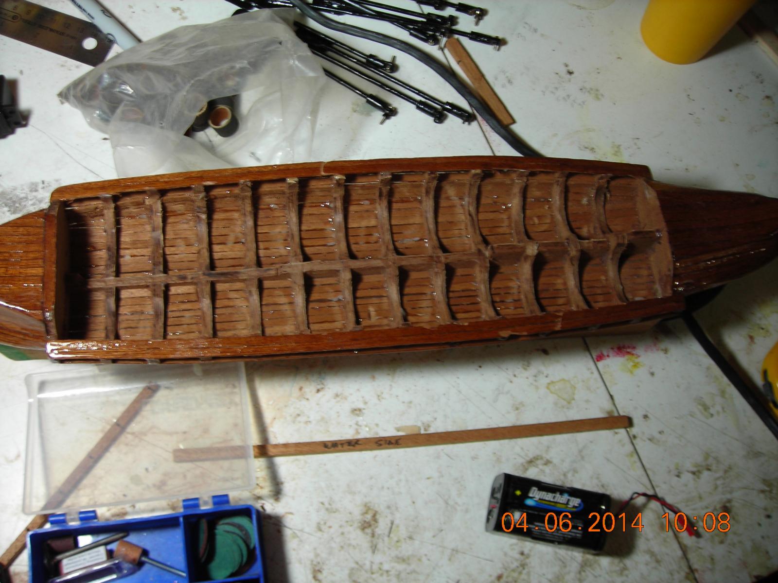
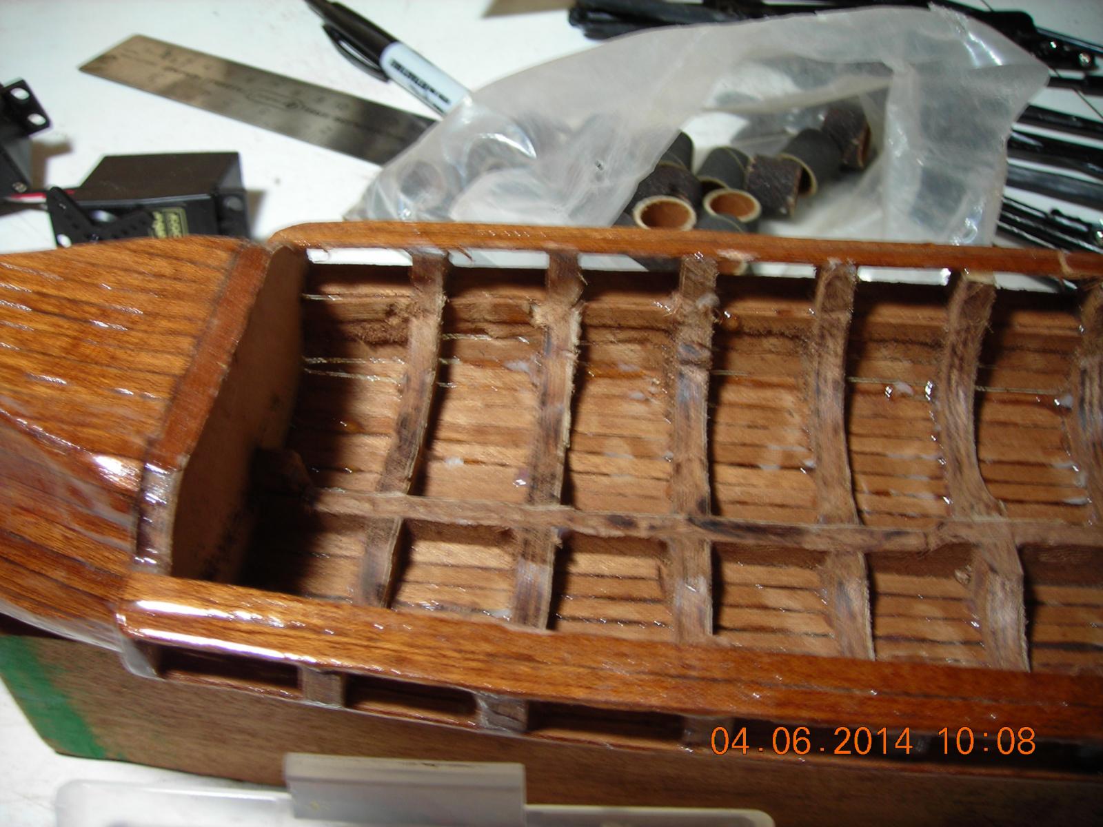
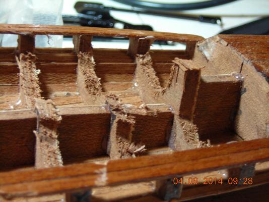
 This post shows the bulkheads during alteration. What appears to be a drill bit is actually a cutting bit that can do a lot of destruction in a very short time so I had to use two hands for this part in case it went astray. One picture shows the type of cut this tool does very quickly and very roughly this of course is the initial cut. The other pictures are the result of sanding with a Dremil barrel sander and finally the one picture shows the keel cut away to fit the batteries and two servos. Next the mechanics and now that I have a final design worked out I'll keep you posted.
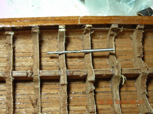


-
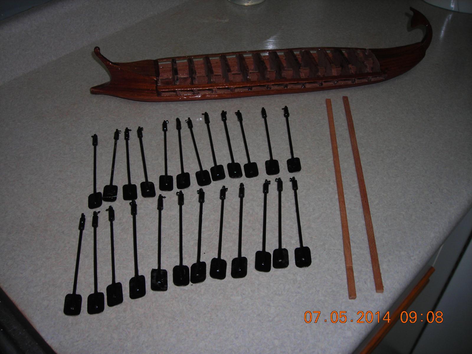
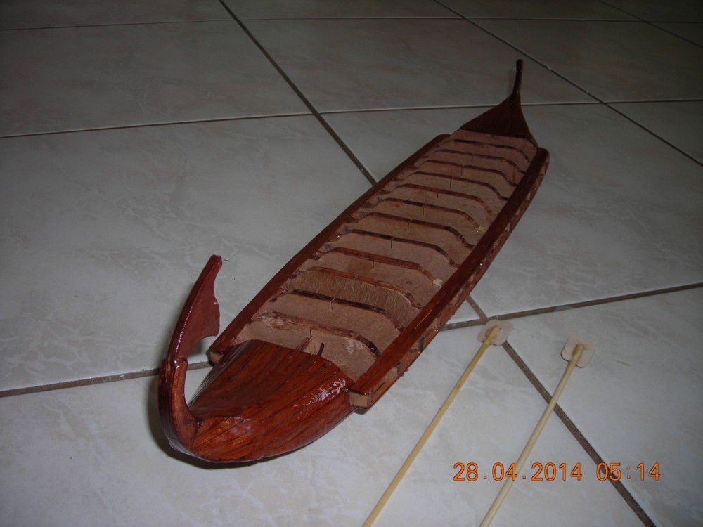
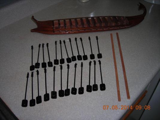
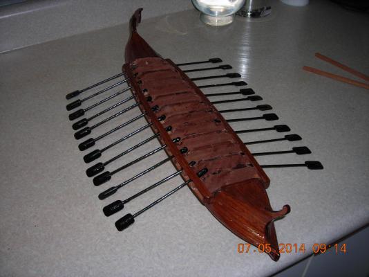
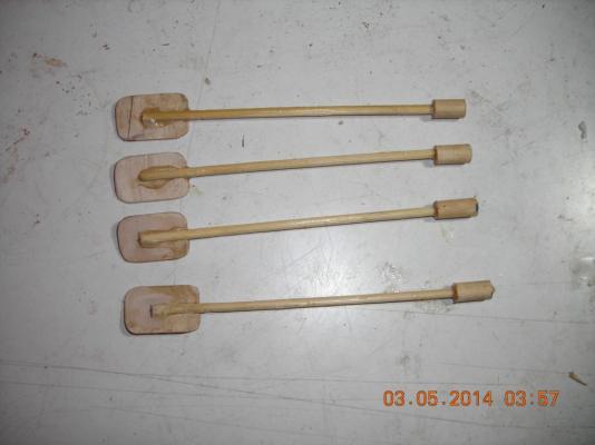
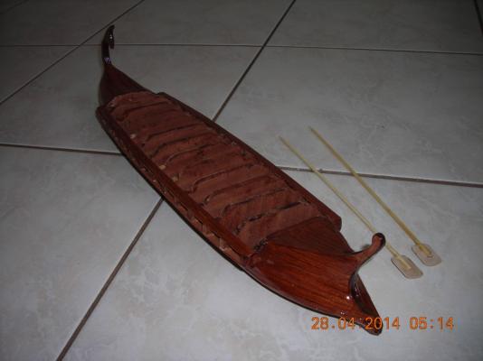
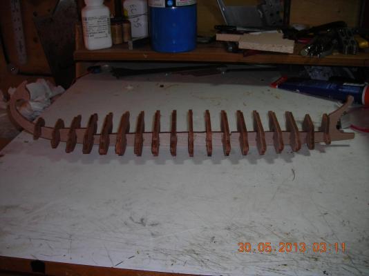
Picture of the oars in their completed state and what they should look like when being in operation. The end on picture of the stick end is actually one of the racks the oars will be screwed on to there will be one rack per side. I cut the racks on an angle so the oars will be able to move without binding.
-
Thanks I'll check that out
-
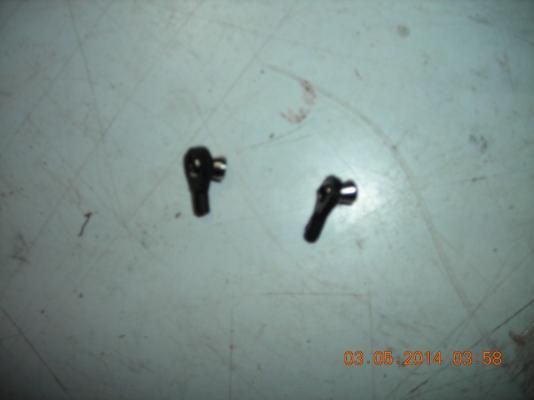
This shot is looking at the installed link end view. Lousy picture but a great shot of my Dremil bits kit I bought from Canadian Tire last year for ten dollars best deal I've seen on dremil bits made in China but so far have worked very well for my needs.

-
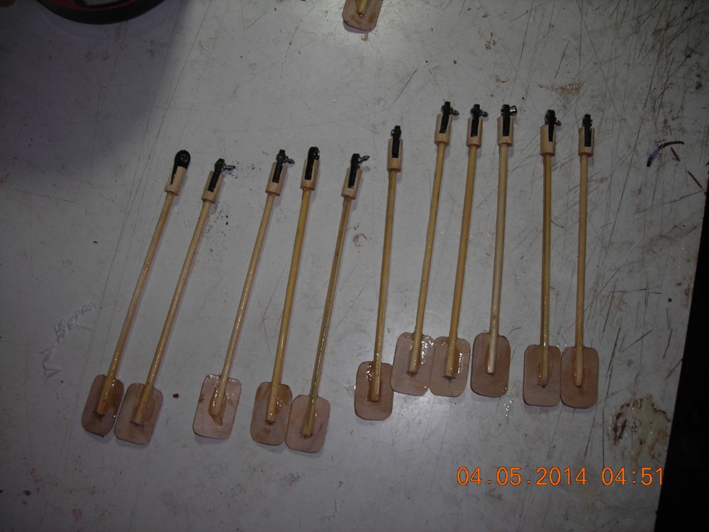
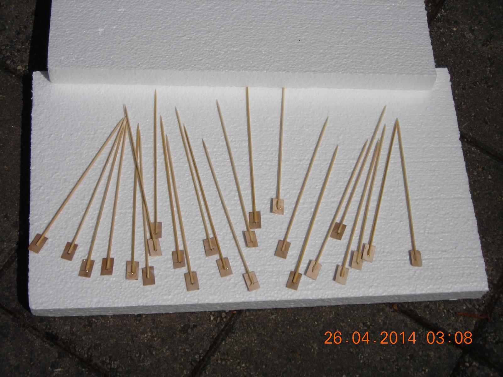
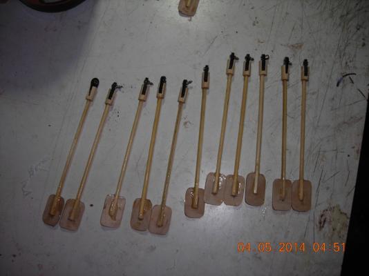
The oars with the links installed but not yet epoxied, twelve done twelve to go.
-
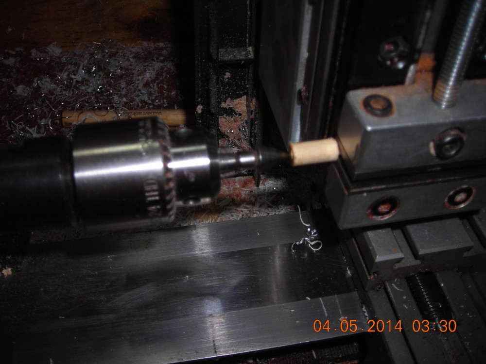
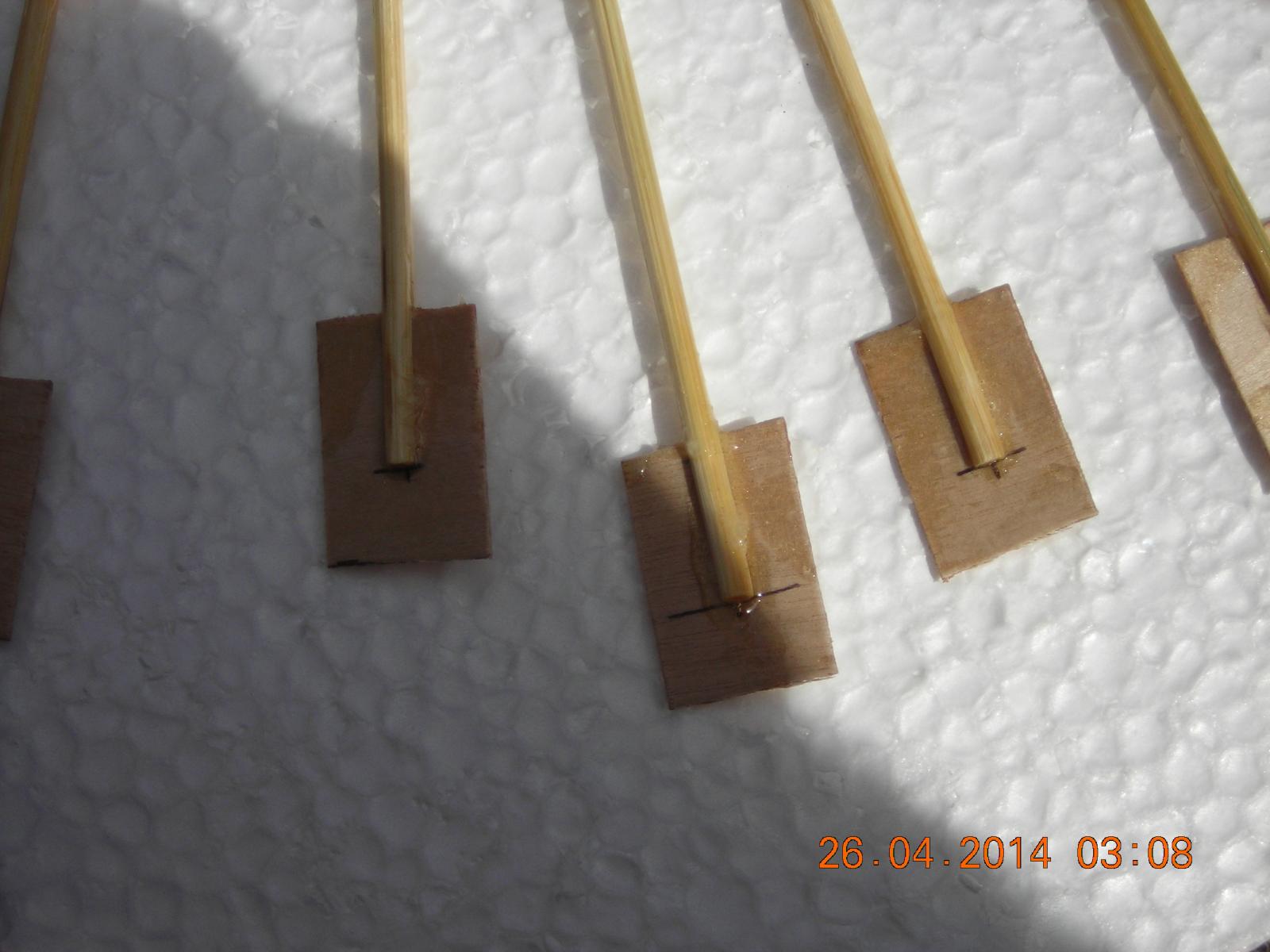
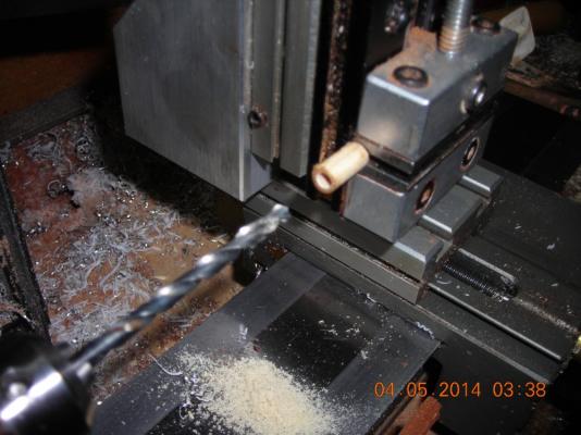
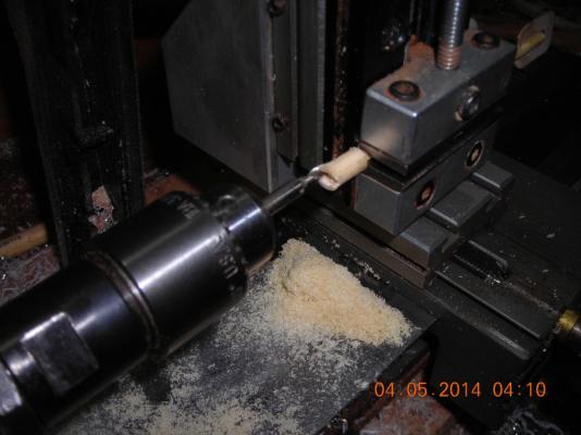
The drilled end on completion of drilling, the milling of the slot is in the next picture. I'm milling a slot into the dowel so the link will slide into the oar end and prevent any turning of the link in the oar end. I took the picture while the milling bit was being turned at about 800rpm by the lathe but looks like the shutter speed is too fast to get the blur of movement.
-
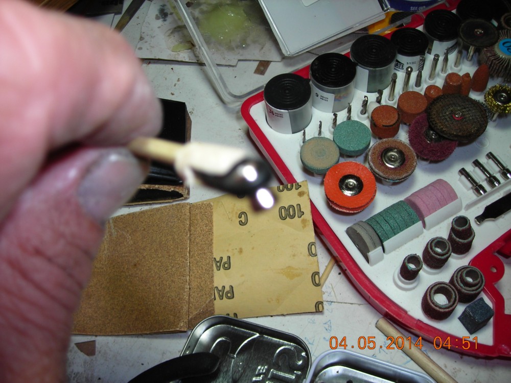
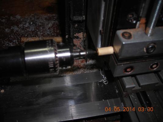
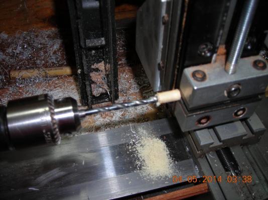
The pictures here show my centering bit I use before drilling to line everything up so it can be dead centre. The other picture is the actual drilling of the oar end.
-
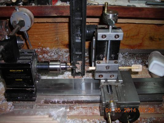
This is my lathe with milling machine attachment getting ready for drilling the oar ends. I would put in more than one picture at a time but this website seems to place them backwards in the post when I load the pictures.
-
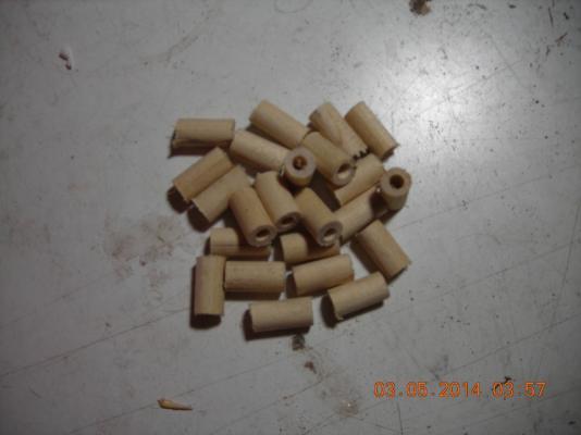
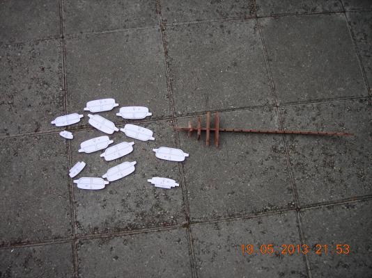
Bottom picture is the oars cut to 5 inches. Third picture is the dowel sleeves drilled to 1/8 inch and cut to half inch long. Second picture is the oars with sleeves mounted. Top picture is the links and balls that will be at the rack end of the oars. The links will be on the oars and will have raised wood around the rack where the balls are mounted this will prevent the oars from turning or rolling. Pictures ended up being backwards in order don't know how I managed that.

-
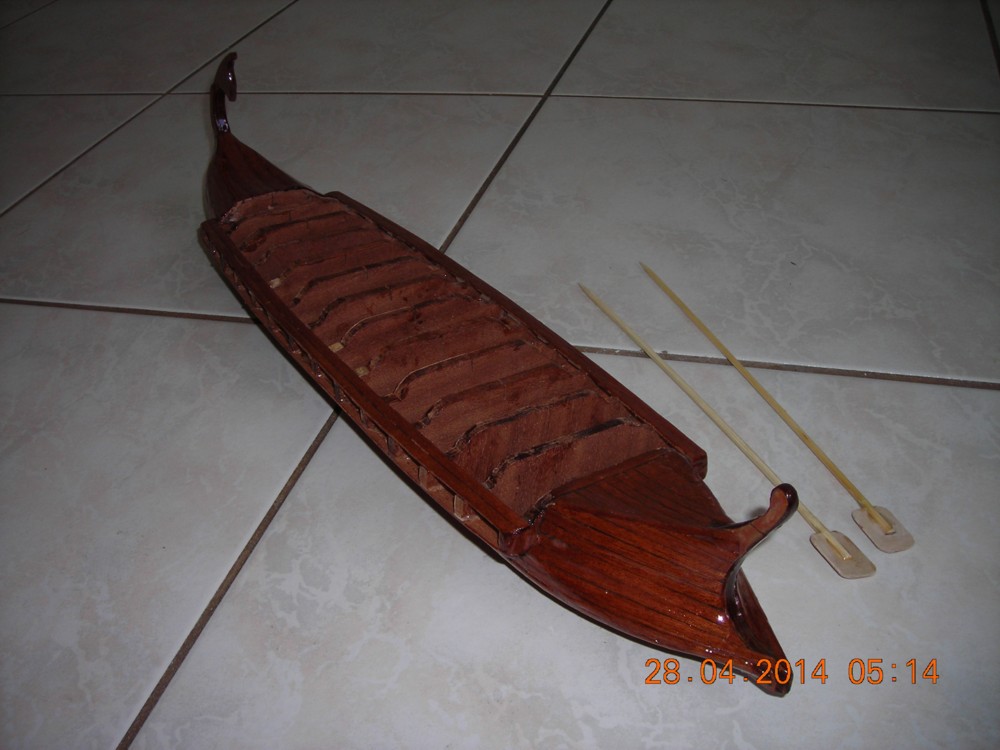
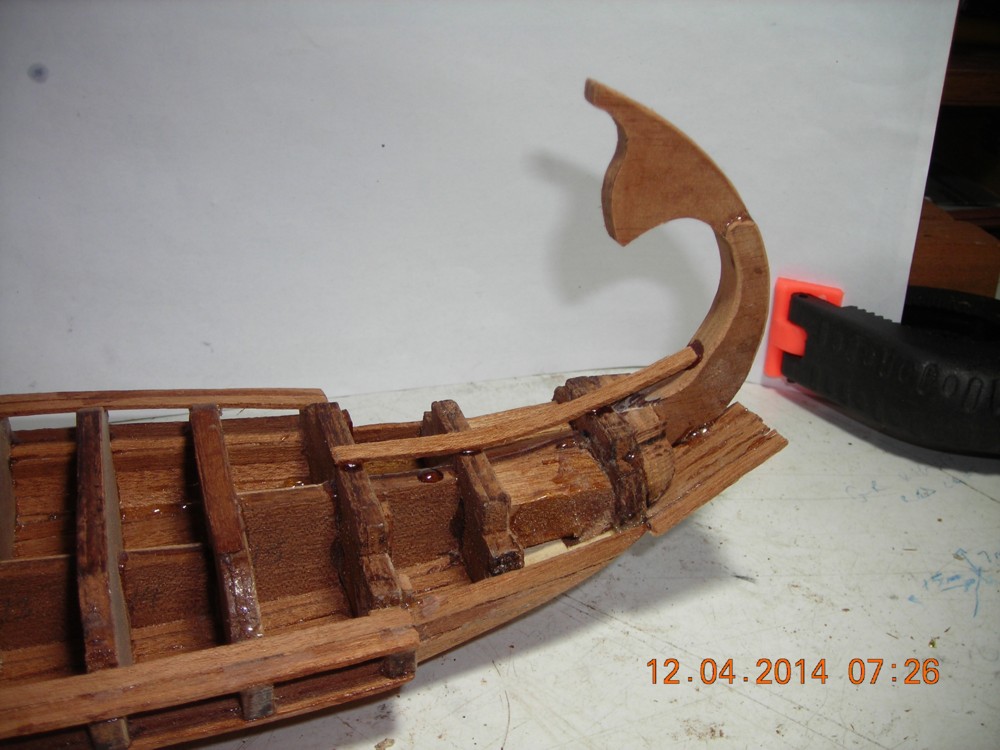
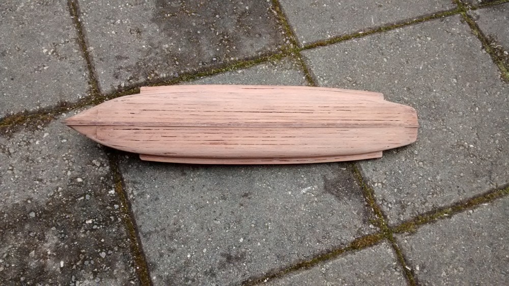
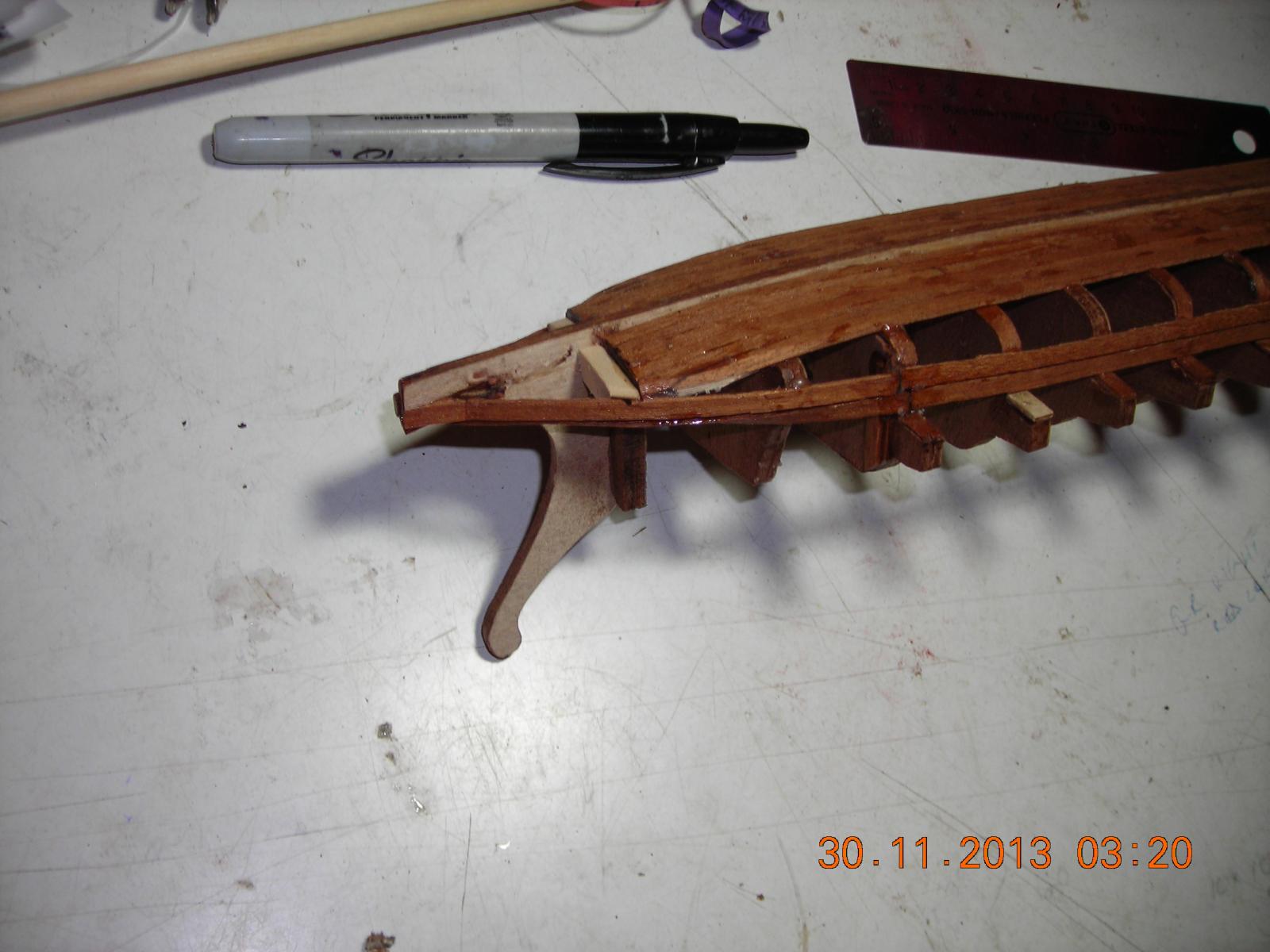
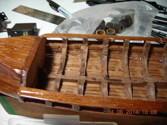
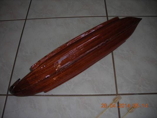
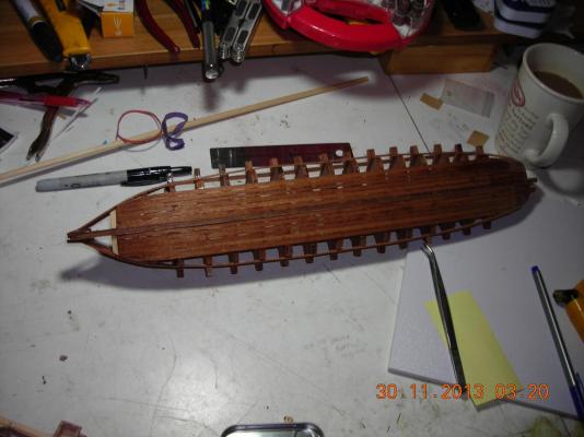
I finished this part of the hull with two part epoxy to make sure it's going to be good and waterproof. The oars have been shaped but I think I want to cut them down and make them more like the real ships had.
-
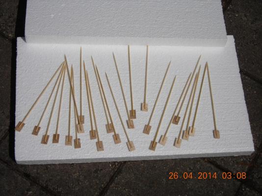
Now the oars! They are made of bamboo skewers and aviation plywood both materials are strong and flexible. The bamboo was split one half inch from the bottom the cut and measured plywood was slid into the bamboo and glued in place with epoxy.

-
Hi Gary well to answer your question the key here is not how much will be put into the hull it is more like how little. What will be in the hull is four servos laid on their sides two for the oars one for the sail and one for the rudder. The other electronics will be a RX battery pack and the RX there is no separate power source or drive motor. The oars will come through bores drilled at the outboard sides of the ship they will then clip on to a rack using RC heli links and balls that tie them all together. At each end of the rack a pin will protrude through what I call a race track that is a guide the pins will follow in their movement. These pins are driven by a slotted wheel that will move the pins around the racetrack guide, the wheels are driven by ball chain from the servo that will centre of the two driven wheels. The power for these wheels has to be chain driven due to the need for timing both ends of the rack to run in parallel with each other. The servos which are Futaba 3003 are old school style servos and can be altered to run continuous in either direction. My radio is a Futaba 12 FG which is an aircraft radio that can allow me to mix channels if need be for the oars but I think that won't be necessary, the radio does however have two rotary knobs that will be used for tilting the sail and operating the rudder because they can be set to hold their position at any angle I choose. One more thing is the hull will be gutted as required and if need be braced in key areas for support. These things will be documented with pictures as I go along.
-
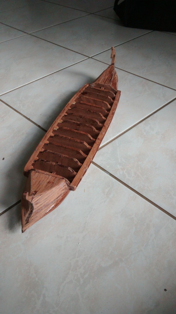
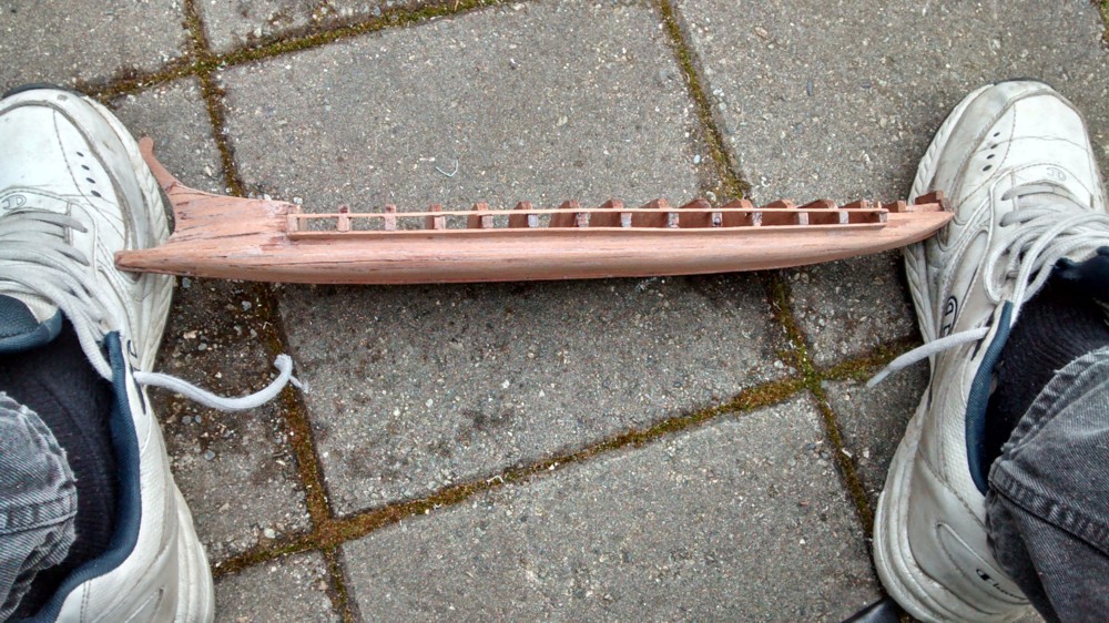
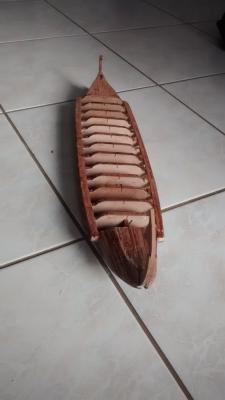
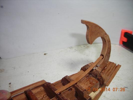
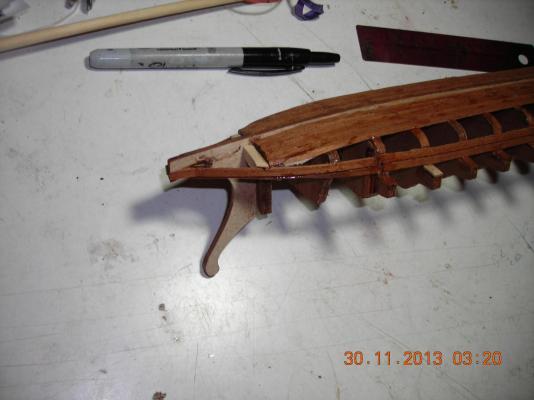
More pics of the stern I hope to have it sanded after the weekend and then it will be time to build the mechanics. That is my favourite part because it takes more thinking and creativity.

-
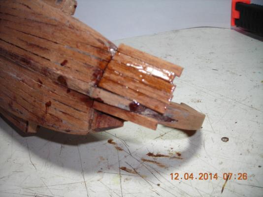
More progress pictures. Believe it or don't it should look OK when finished I'll do my best to do a good job of blending the wood to have an acceptable look. I have been on another website and picked up some ideas regarding connecting the oars that should make a simpler and better operation. I will be using links and balls from my spare helicopter parts collection to clip the oars on the rowing beam.


-
The oars will be powered with one servo on each side, I've converted them by removing the stops so they can run non stop in both directions. The oars will be anchored at the port and starboard sides to stop them from sliding in or out of the hull and pinned or slotted to prevent the oars from rotating. The oar dowels will then go into a drilled board that will be moved using pins that will follow a machined "racetrack" guide fashioned to imitate human movement rather than flail around in a circle. The "racetrack" pins will be moved at both ends of the drilled board by a slotted drive wheel driven by bead chain from a machined pulley all the pulleys will be timed and machined to be non slip. This setup will allow fluid movement of the oars at any speed, it will let me dip one side into the water while the other side powers a turn or power one side forward and the other side in reverse to turn in a circle. The machining will be tricky but then again this is the part of the build I look forward to the most.
-
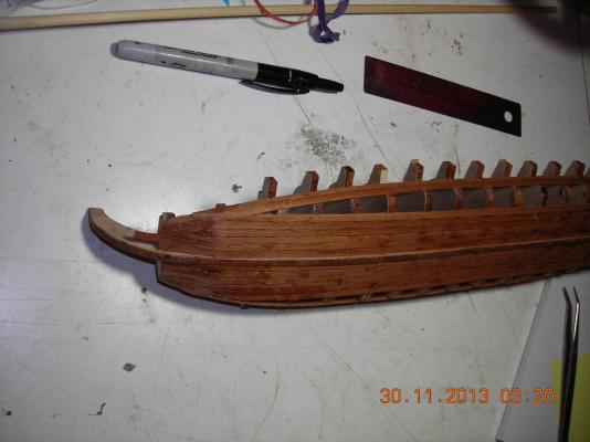
This is the start of the hull planking. The wood I'm using is African Sepili hardwood that I cut from larger stock on my little home made table saw. Not the greatest wood to model with but it was actually scrap wood left over from the company I worked for that made made luxury vessels that ran about 25 million each. The price was right (free) so I'm taking advantage till I run out.

-
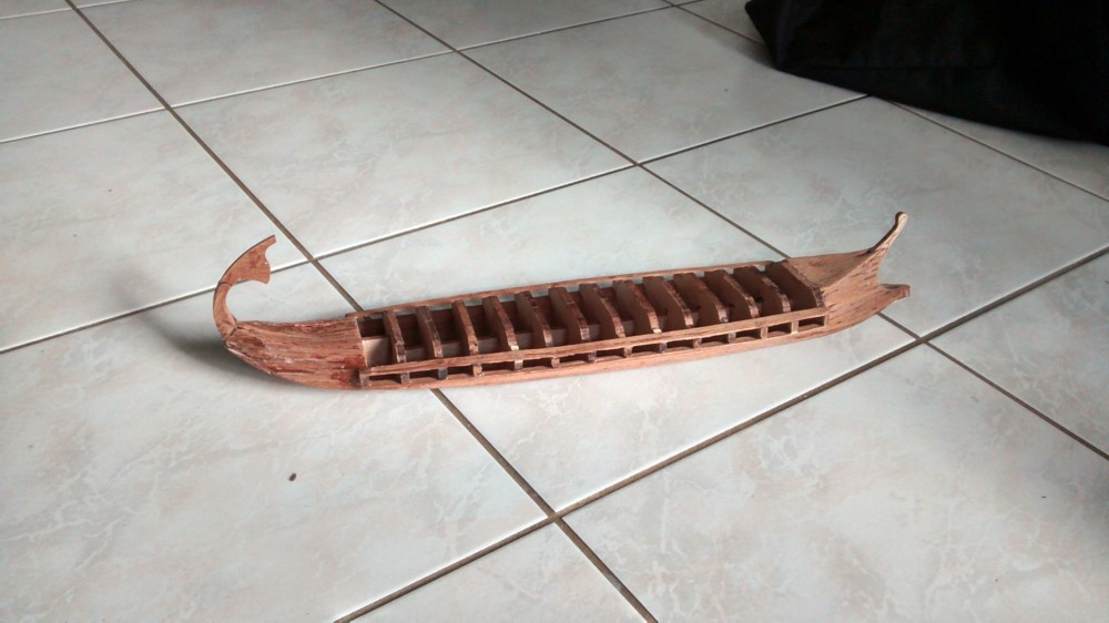
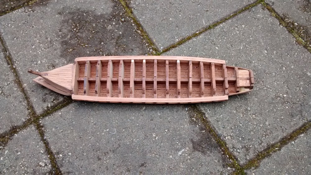
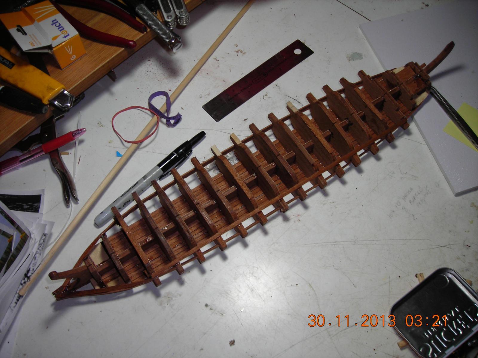
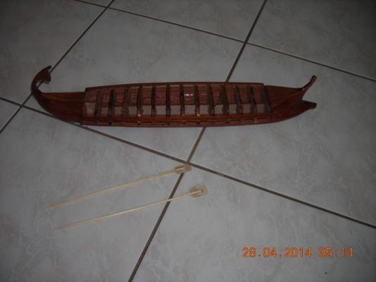
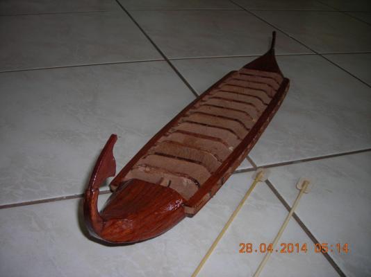
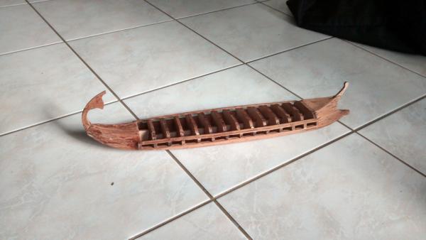
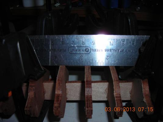
The picture with the ruler is to give you an idea on the size of the vessel and the space I will have to make my mechanics function, the other picture is the start of the planking. Once I have the hull completely planked I will alter and remove certain bulkheads to make space for four servos, one RX, one RX battery pack and the linkage that will run the oars. Two servos will operate the oars the other two servos will operate the rudder and sail. I know some are wondering how can two servos do all the motion of both sides of oars, you will get the idea when I post the video of the oars electronics in motion.

-
Thanks Tim, M Taylor, Michael and Aussie. I have the motor propulsion system made and it does function I'll do a video of it operating when I remove it from storage. I'm still in the thinking stages of how I'm going to make it work the way I want to.
-
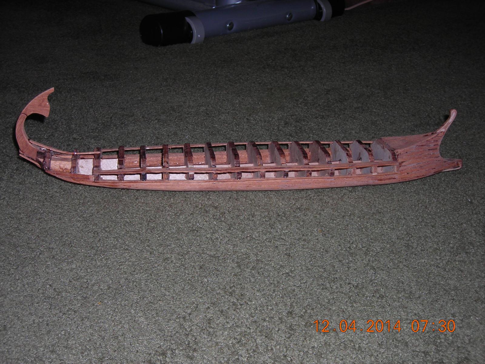
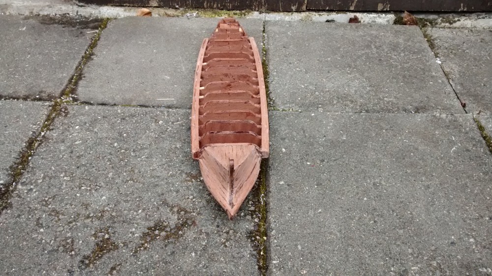
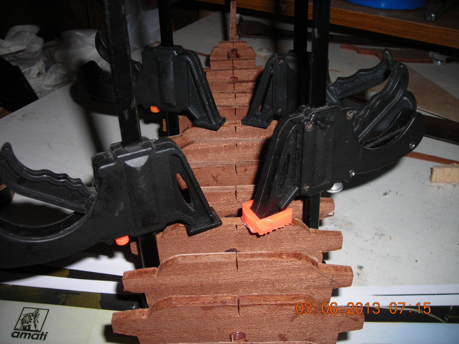
I have another picture this one is all the bulkheads in place. I used epoxy on every part of the hull because water will not affect it and I find epoxy much stronger and faster than glue.
-
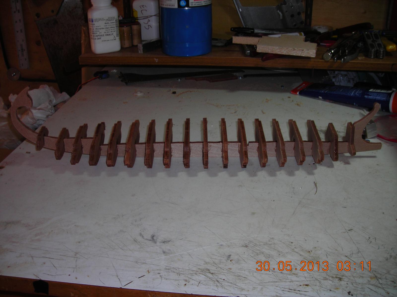
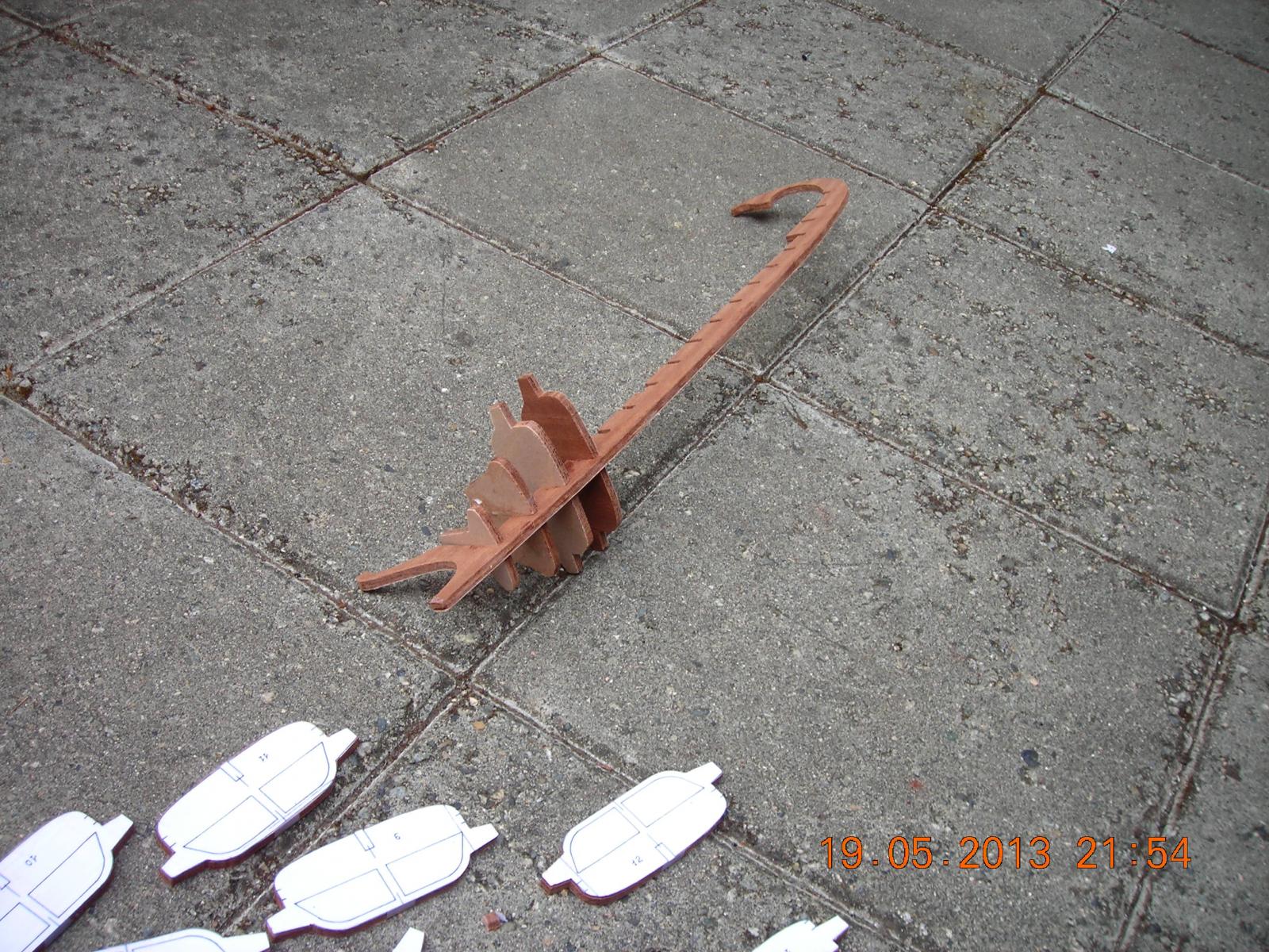
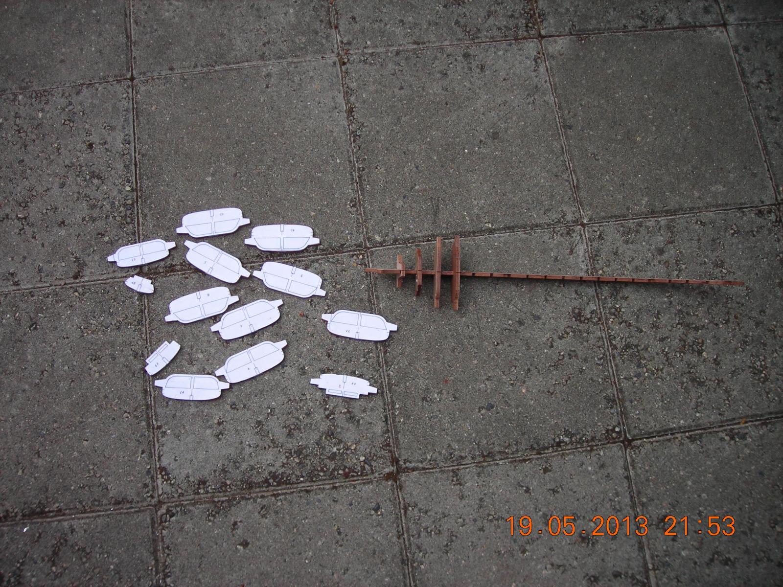
I copied some plans of the Greek Bireme from a fellow modeller and made my own templates. This build is not going to be accurate as far as scale goes my main focus is the mechanics that operate the oars. To do this I require a boat to put it in and the Greek Bireme seems like the simplest multi oar build I could find. The plan is to have the oars and sail controlled by RC too. The radio will be a twelve channel Futaba with a fourteen channel receiver which I believe should be more than enough channels. Lets start with the boat shall we. The two pictures you see are the start with the keel and bulkheads.

-
OK Thanks.
-
Borrowed the plans and made my own templates. One picture shows the templates and keel with some bulkheads epoxied to the keel.