HOLIDAY DONATION DRIVE - SUPPORT MSW - DO YOUR PART TO KEEP THIS GREAT FORUM GOING! (Only 24 donations so far out of 49,000 members - C'mon guys!)
×

bensid54
-
Posts
531 -
Joined
-
Last visited
Content Type
Profiles
Forums
Gallery
Events
Everything posted by bensid54
-
 Thanks Mark but this website won't let me copy and paste so that is unfortunate.
 -
Because I can't download video on this website you can find it at you can find it on You tube under Big Bireme oar mechanics working
-
Doubt if this works but here are the oar mechanics at work. I would download the you tube link but it doesn't work on this website. Sorry guys.
-
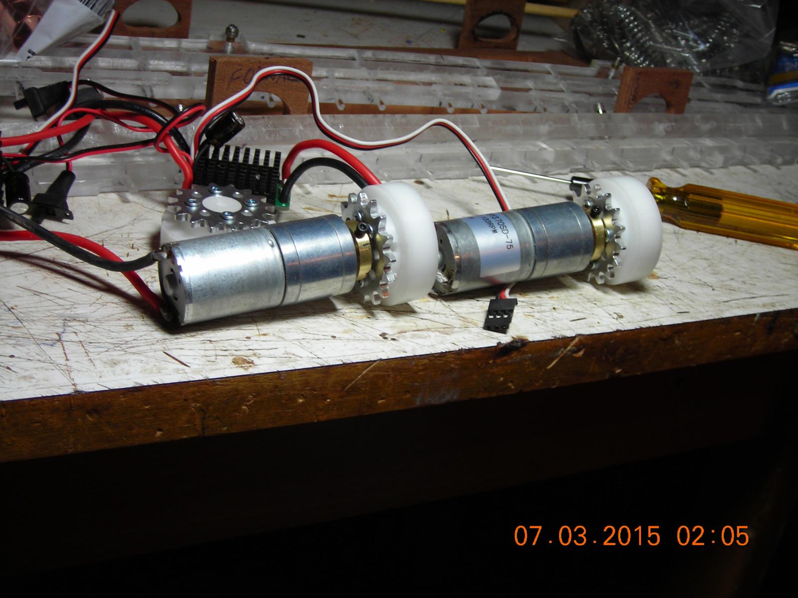
The Mechanics so far, I should have them finished and a video of them working later today.

-
Thank you Patrick I'm glad you appreciate my build! It has been a work in progress from day one when I had a grain of an idea on how I could make a smooth running oar powered RC ship, I have had a lot of back to the drawing board moments since that day.
-
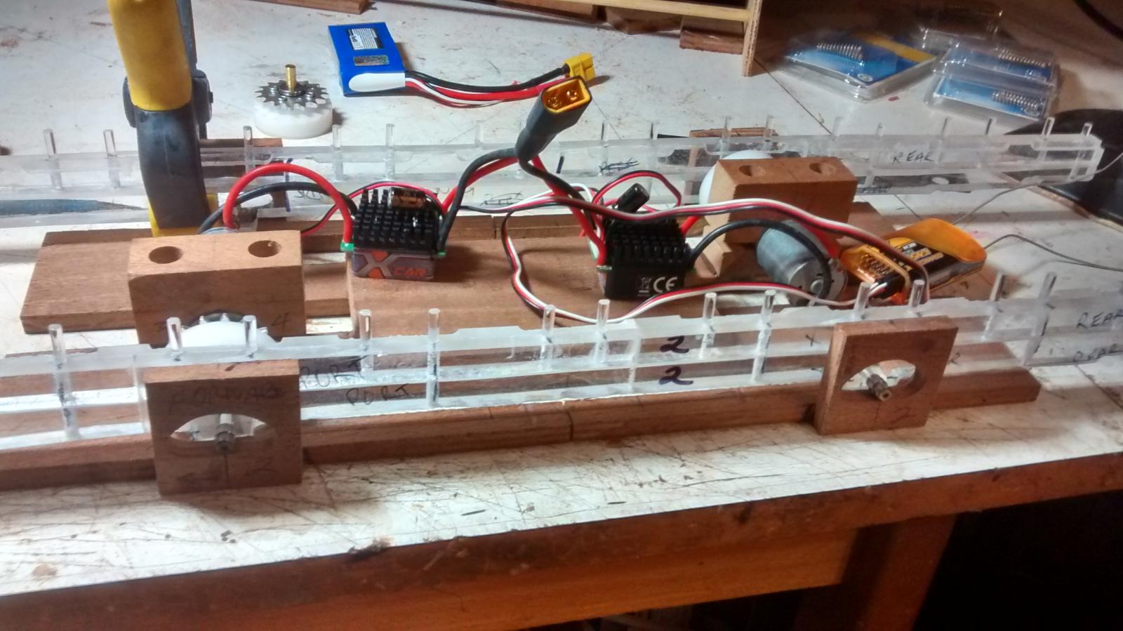
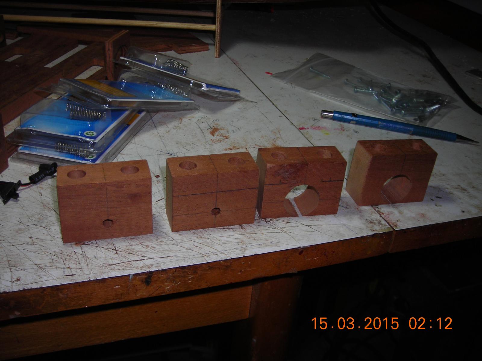
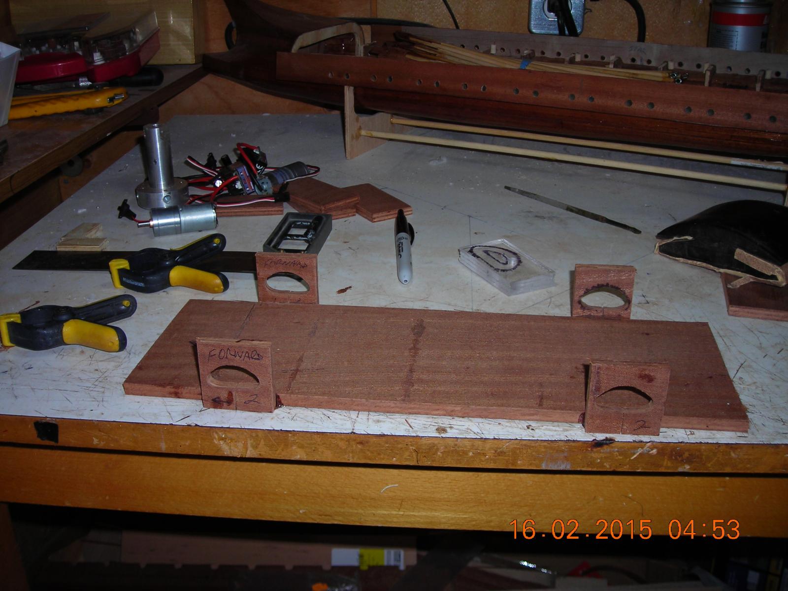
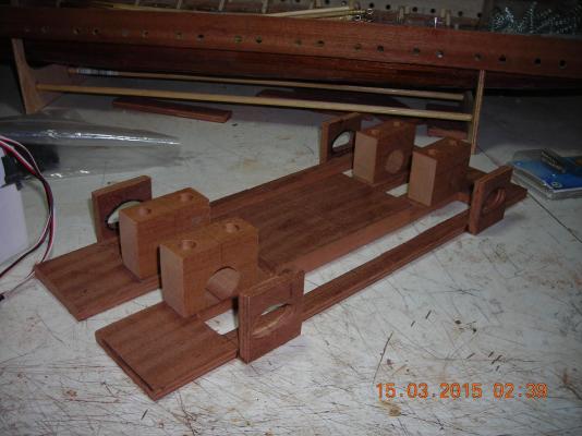
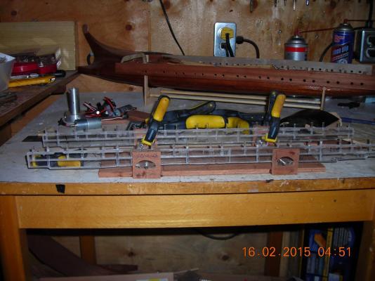
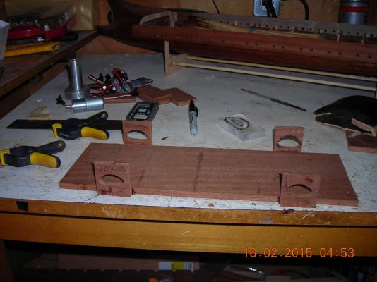
Drilled and cut motor and Idler disc mounts, they are cut horizontal through the axis centre so that when I clamp the motors etc in place with two screws they will be held tightly in line. The second picture gives you an idea how they will look mounted on the motor board.

-
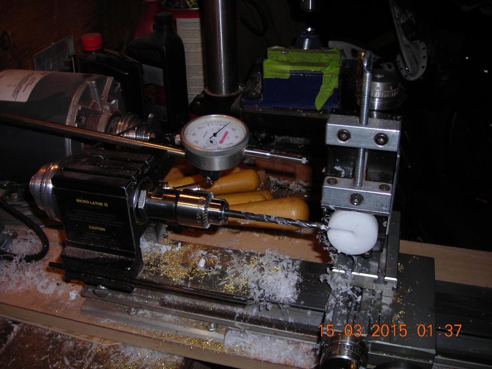
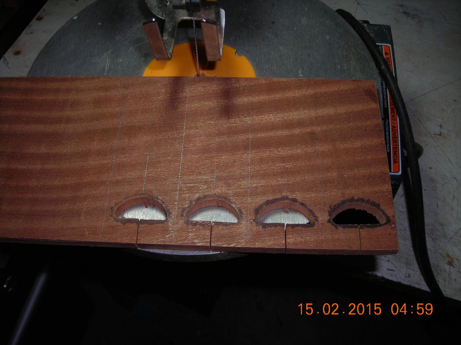
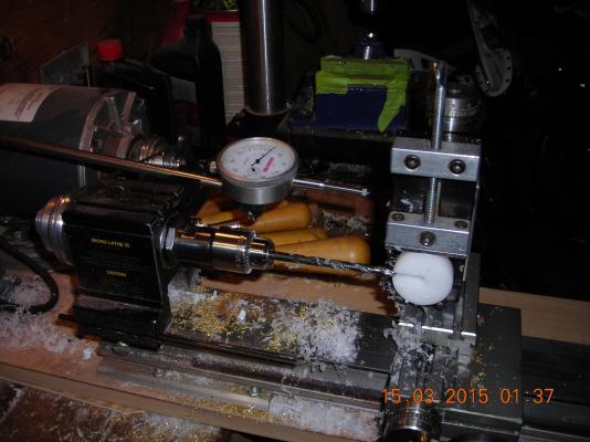
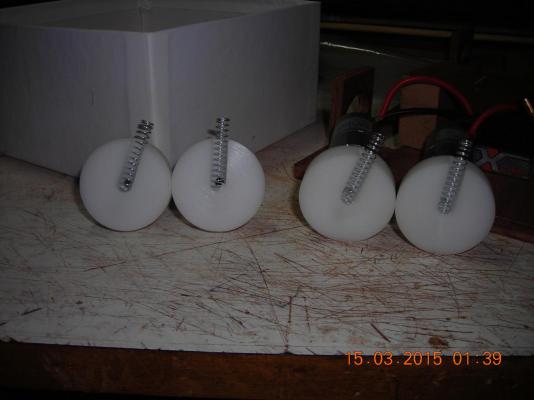
Drilling the disc spring pockets to a depth of .400" this depth allows the maximum amount of spring tension and travel available with the springs I'm using. The second picture shows the springs installed in a relaxed state.
-
I agree Bob I salt away everything and every once in a while I get to use what I stashed. Trouble is if I go senile my parts inventory will be lost!
-
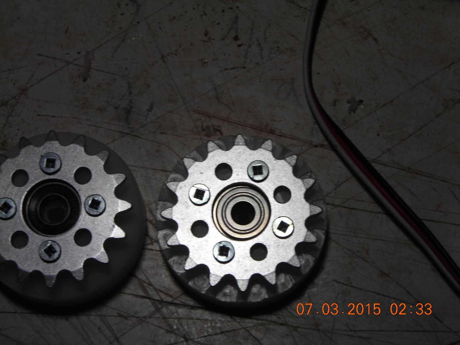
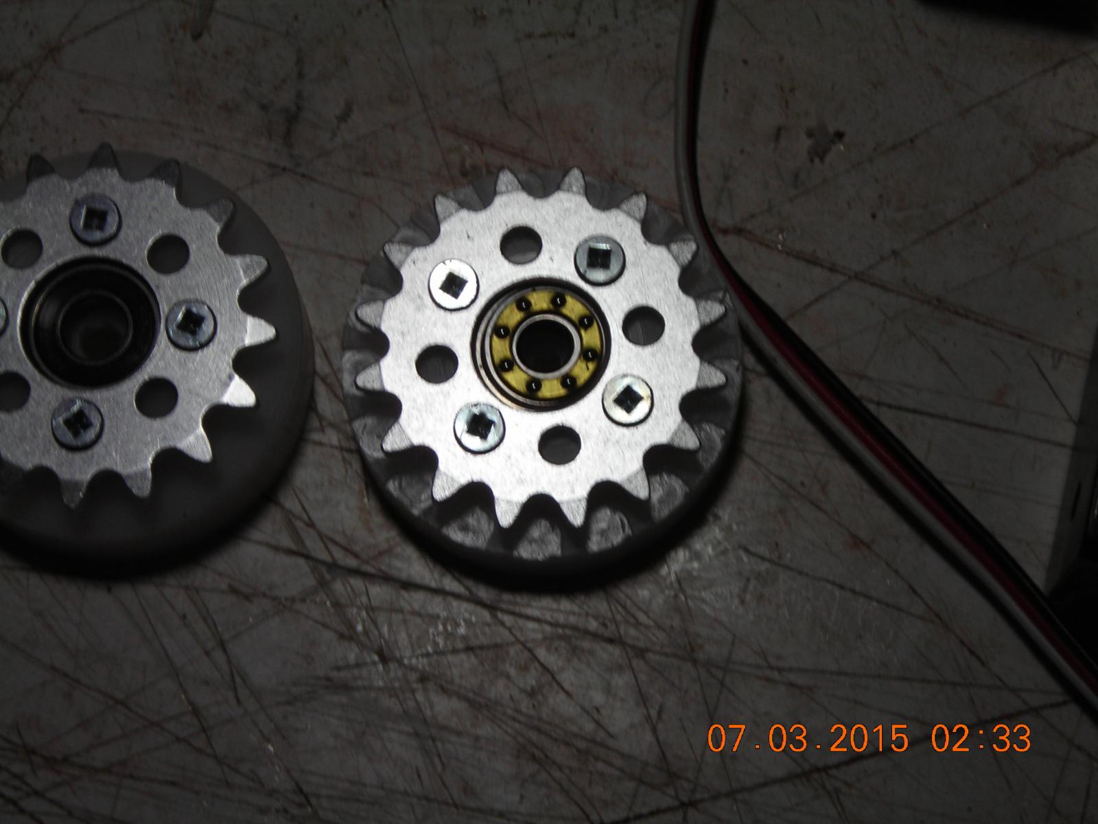
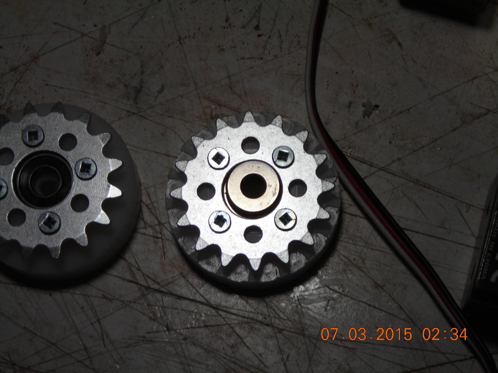
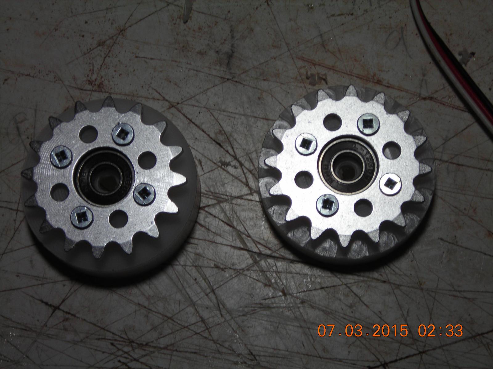
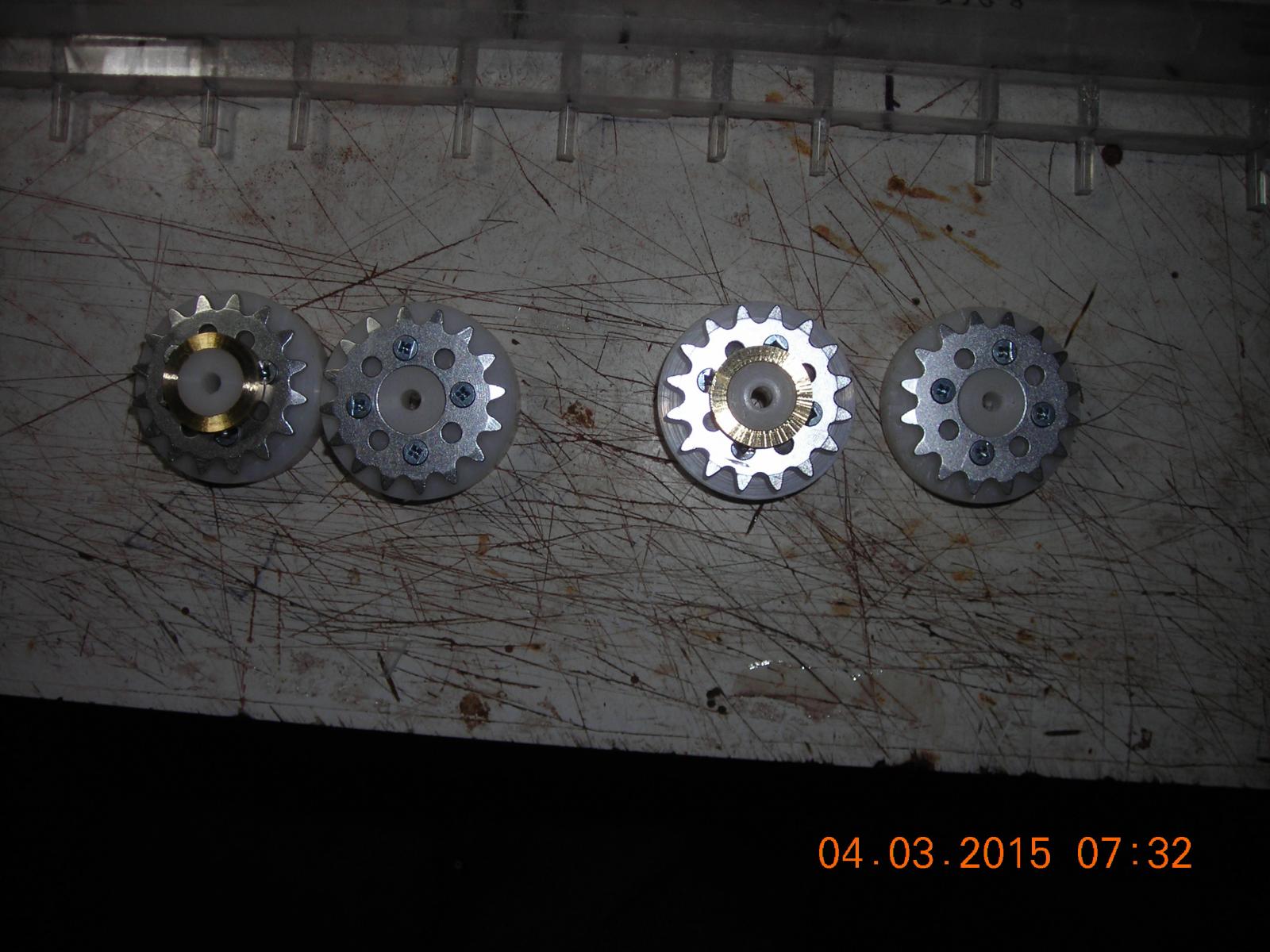
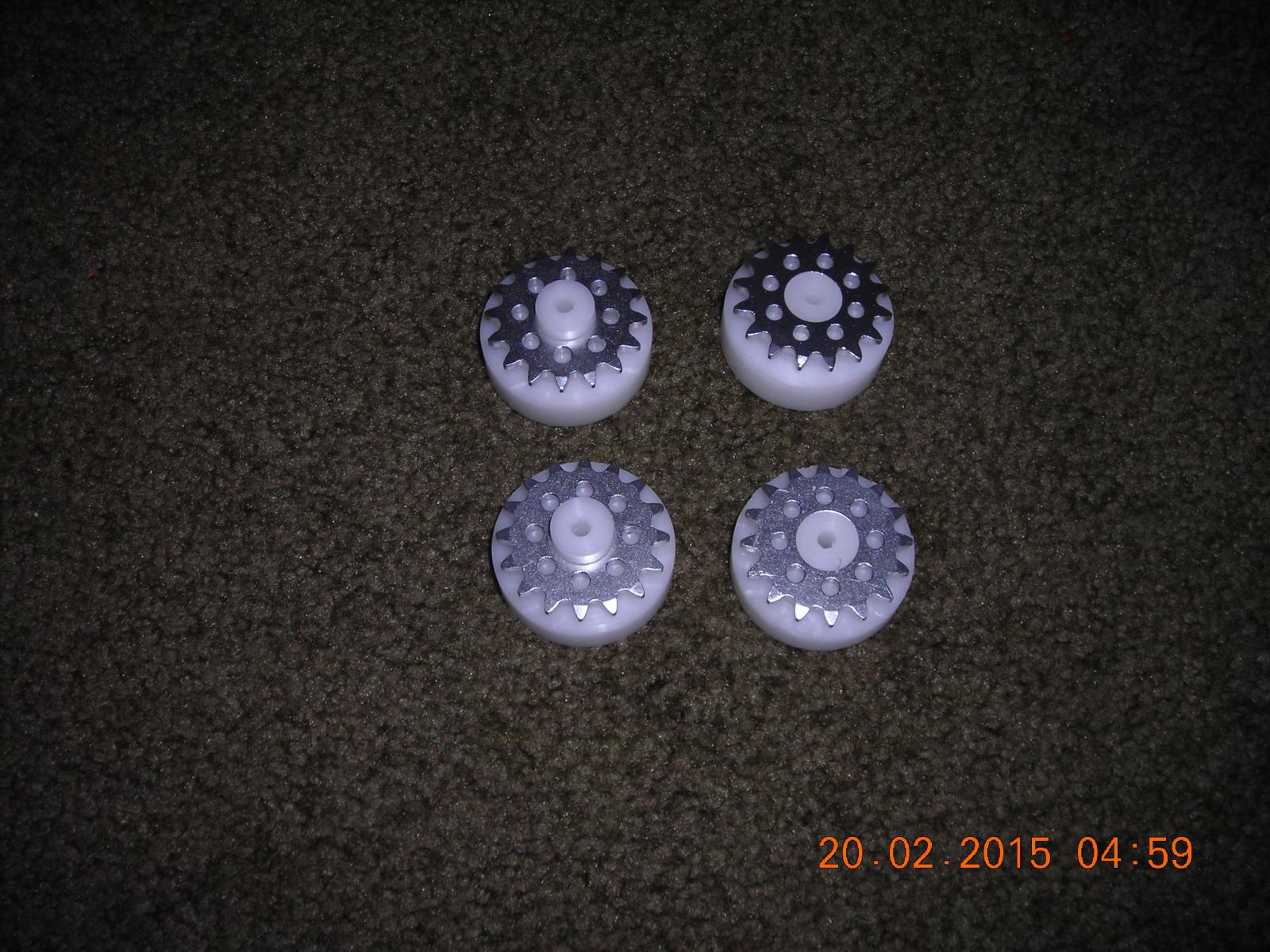
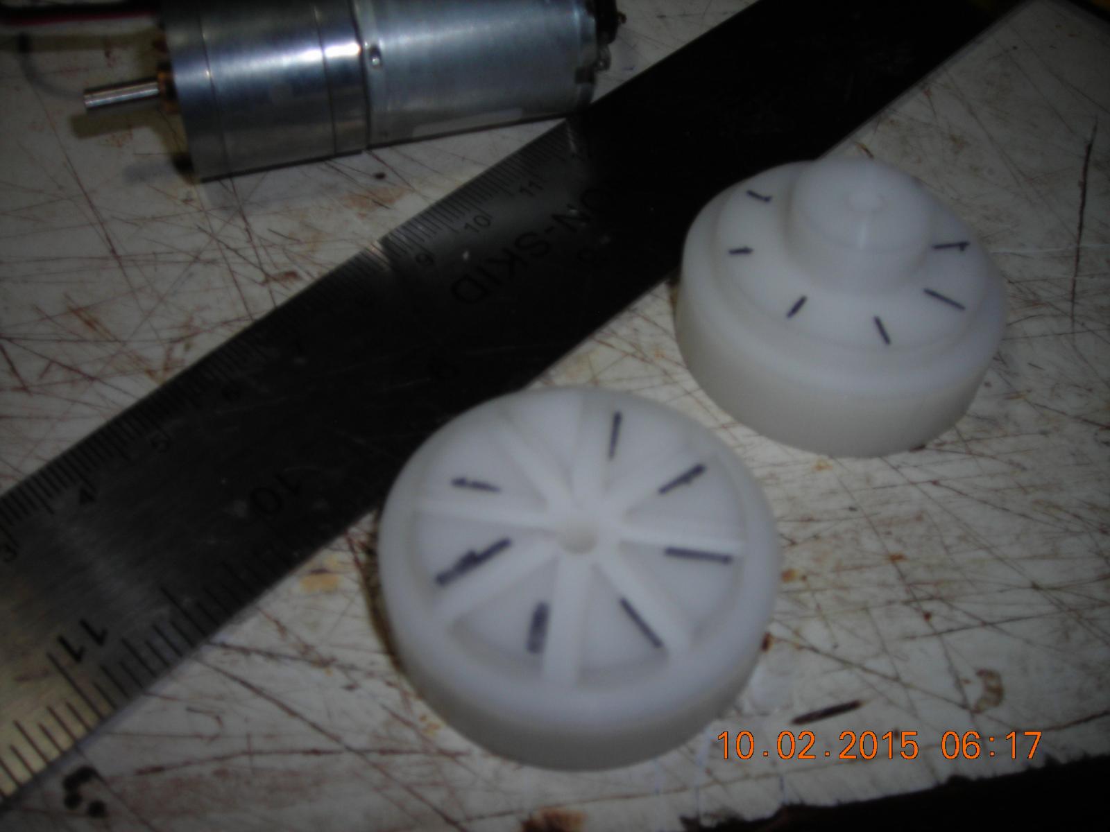
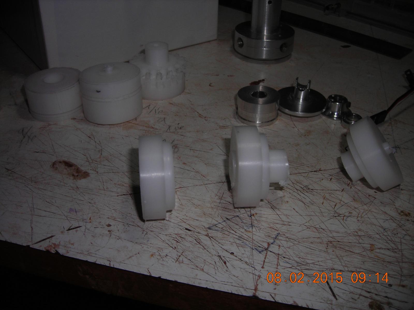
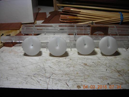
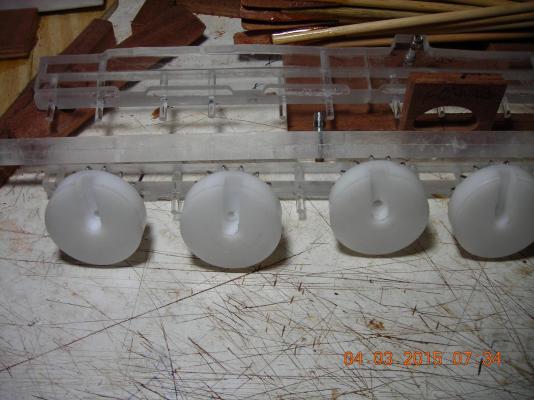
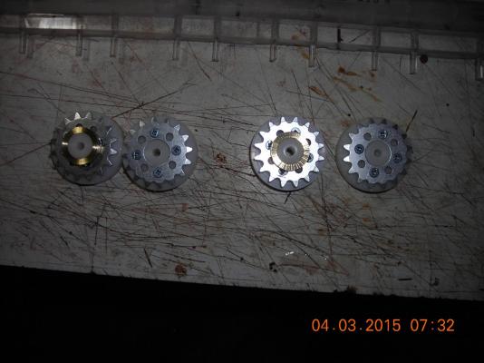
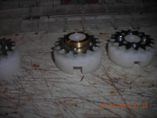
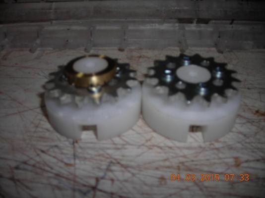
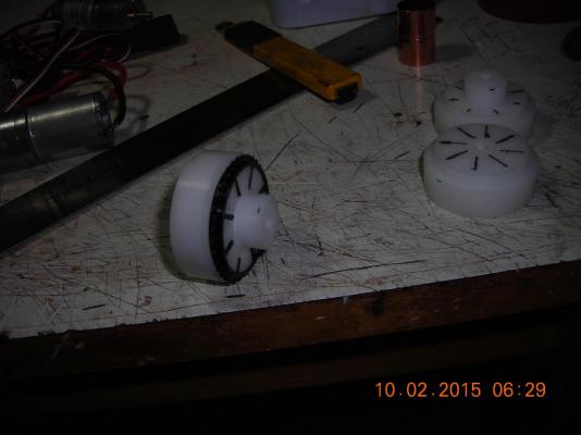
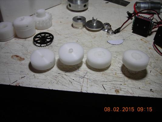
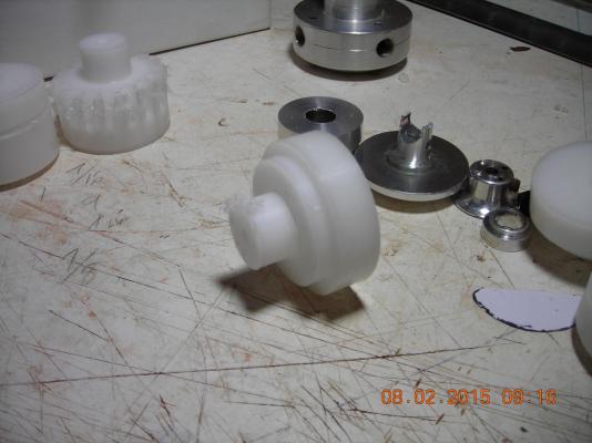
Slotted the faces of all four drive discs then fastened the sprockets to them with four wood screws for each sprocket, next will be to drill the slot and mount springs to force the oar rack rollers to follow the race track. In two of the pictures they are sitting side by side, notice the sprocket teeth compared to the slot in the disc face are the same place location wise, the reason for this is so that I can time them in pairs to make their movement equal. In two pictures there is a brass sleeve on one of the discs pictured those sleeves will be drilled and threaded for a secure attachment to the motors, the ones without the sleeve will be machined to fit a sealed bearing backed by a thrust bearing. After drilling and machining I will be making mounts for both the motors and driven discs and then assembly of the oar drive mechanism will come together.
-
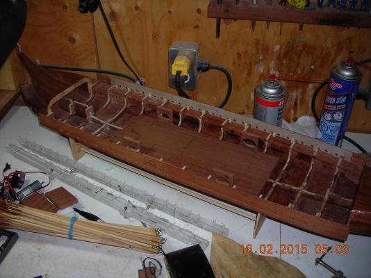
Motor board after cutting out channels for the chains and sprockets, the chains will be running level with the bottom of the motor board and about a 1/4" above the hull bottom. The hull section and upper deck after some sanding and altering to allow free space for the oars to travel in. The oar ports once again will be redesigned to improve alignment, leverage and travel, still a lot of woodwork to be done but I hope to have it in the water by the end of the summer.
-
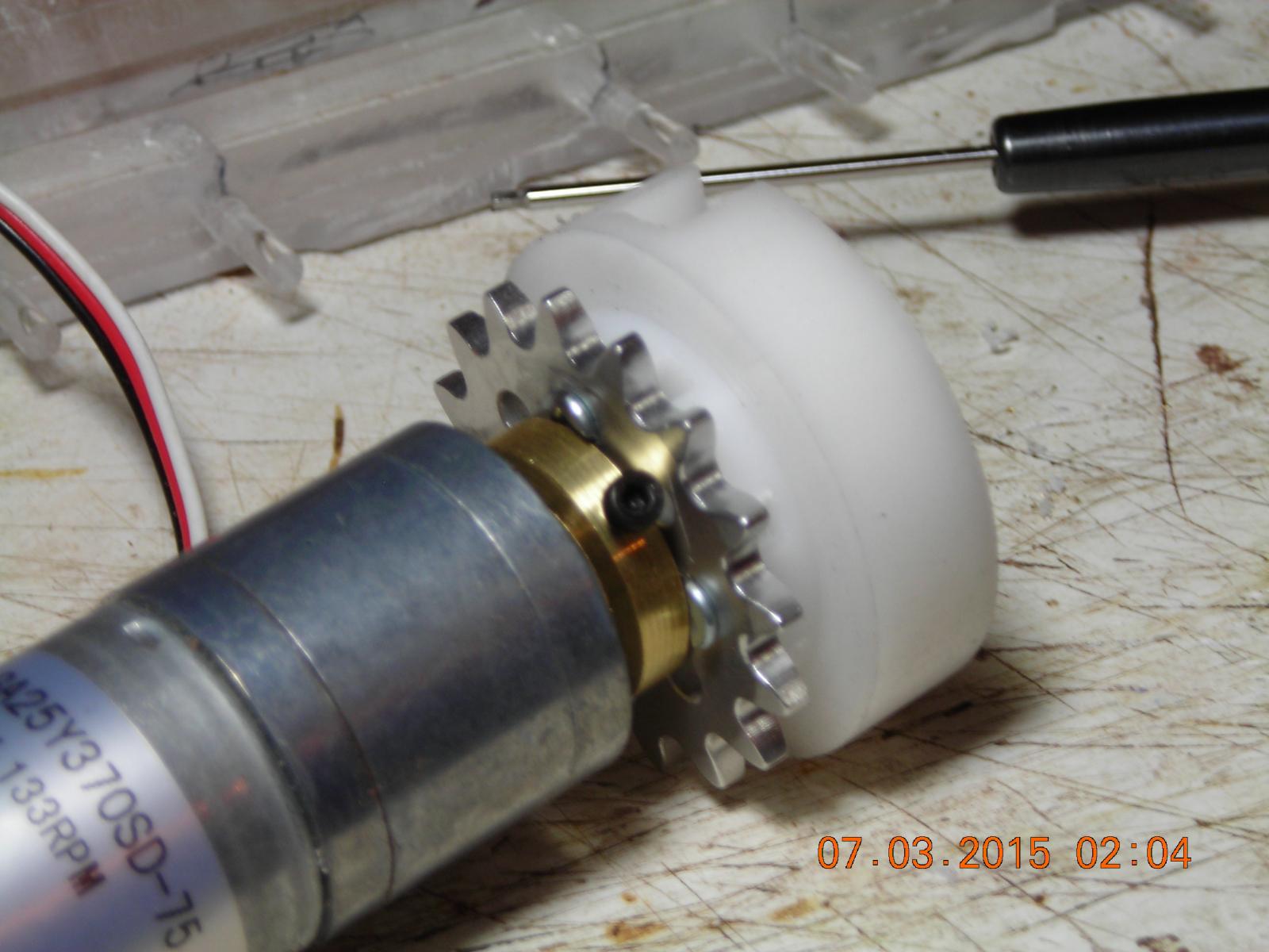
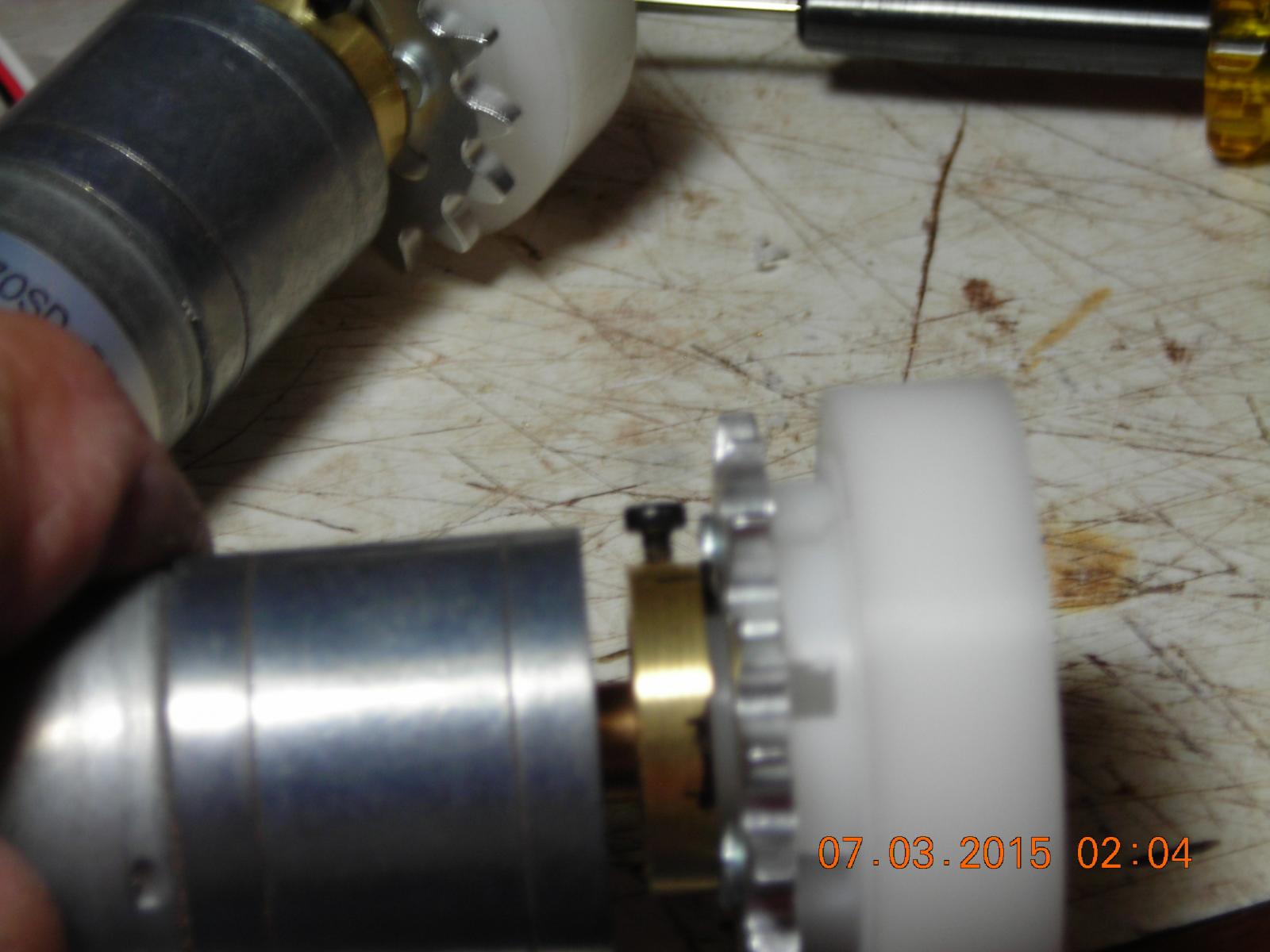
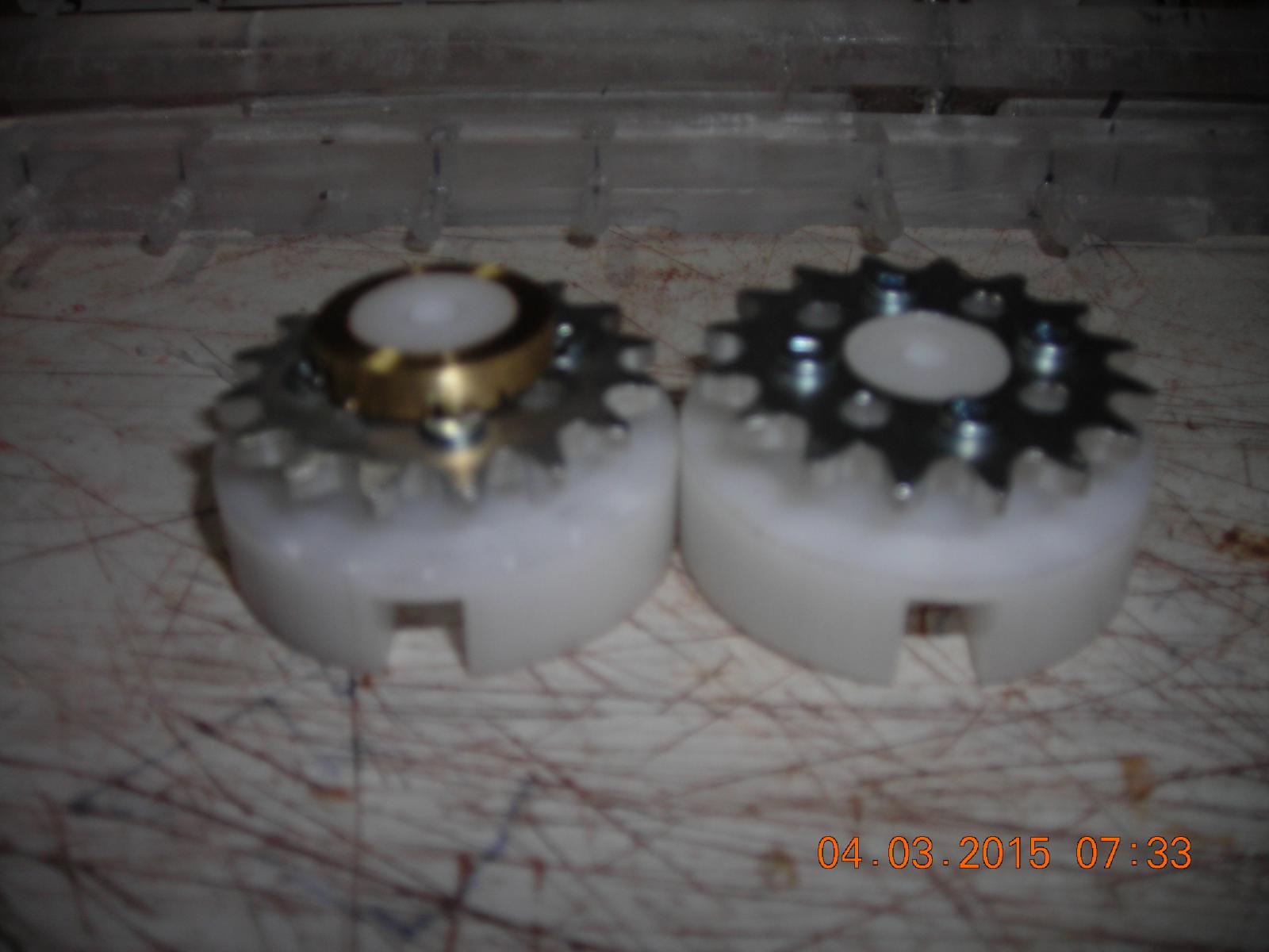
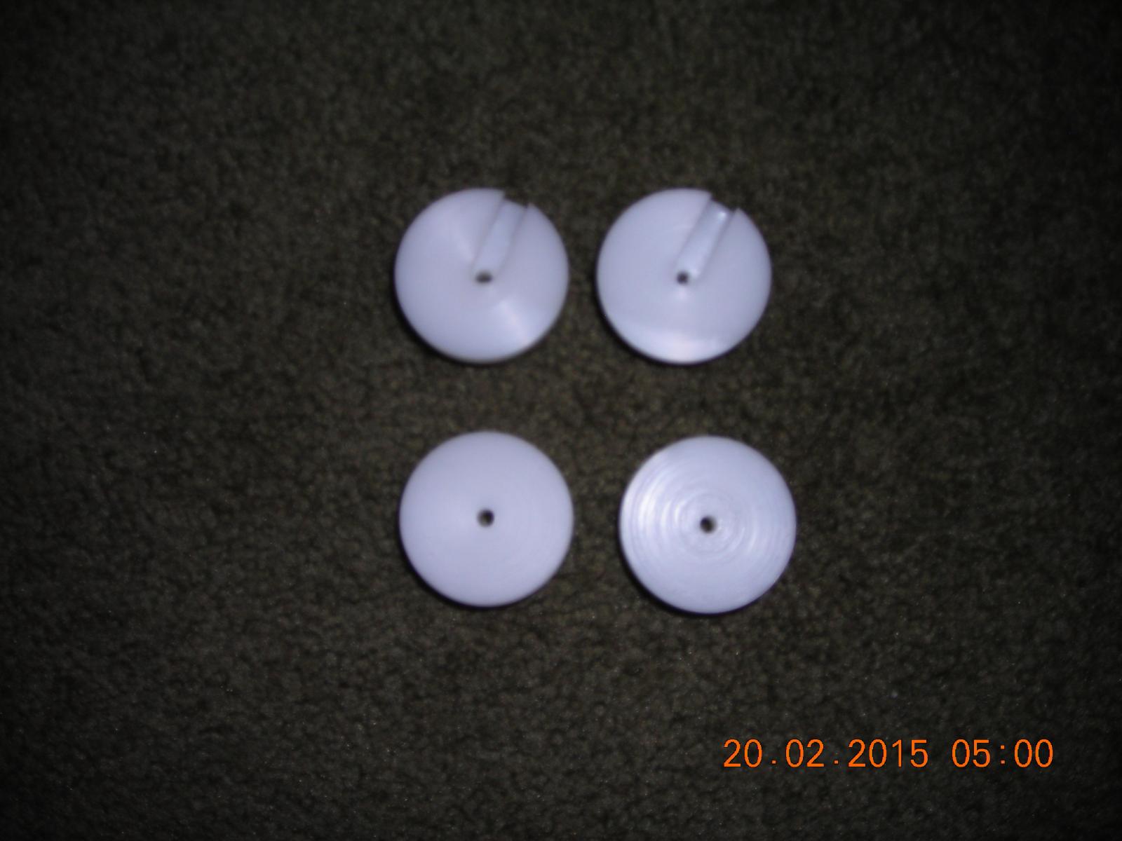
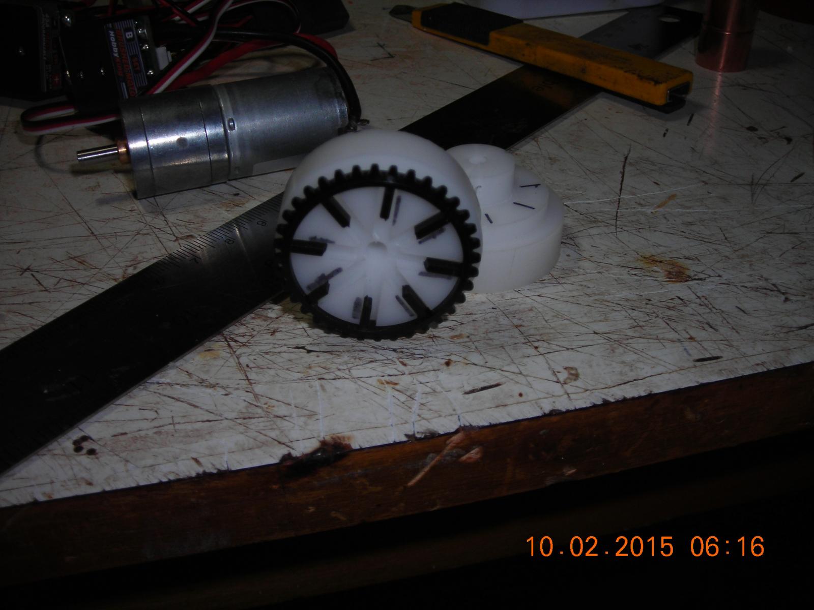
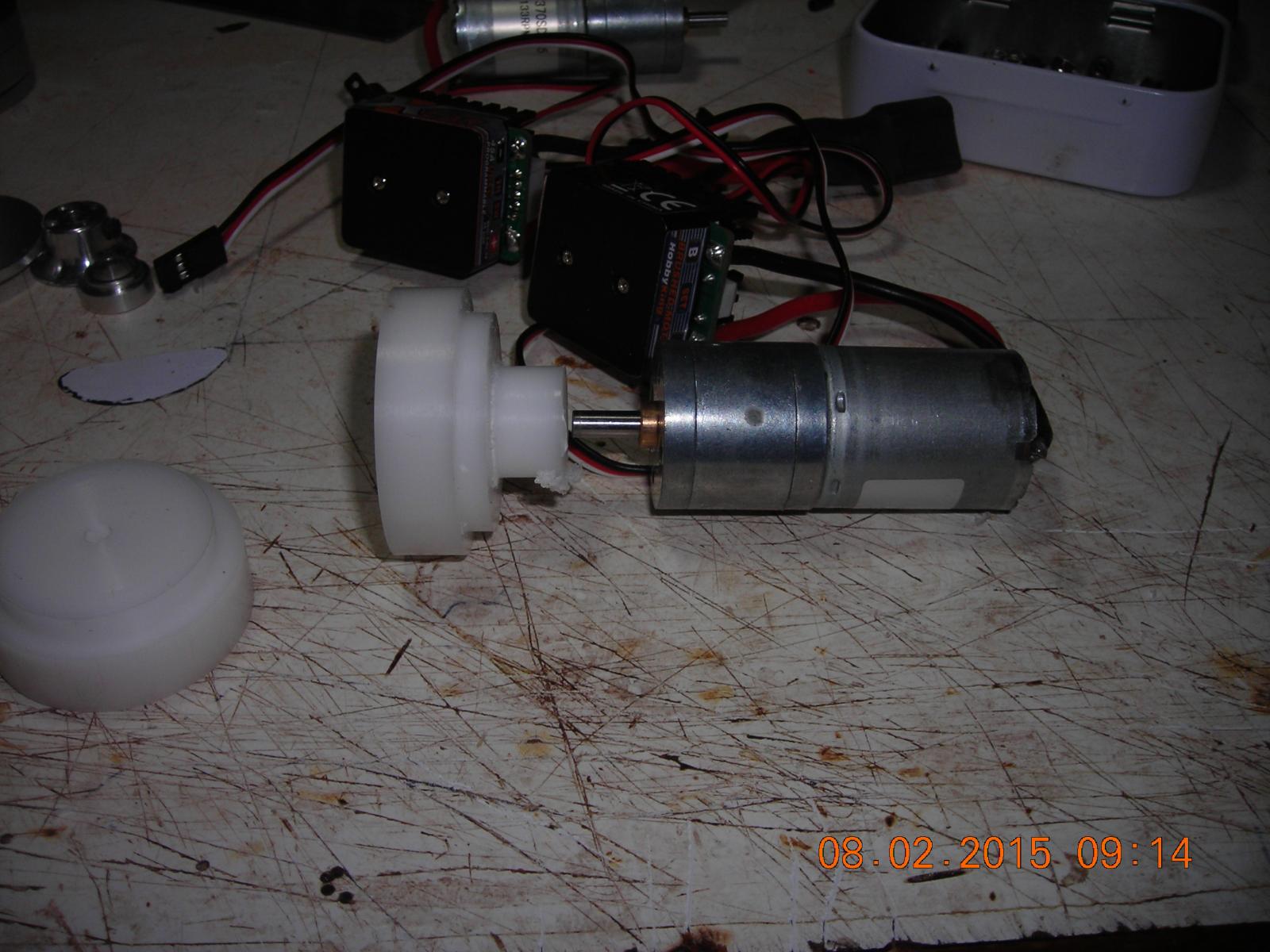
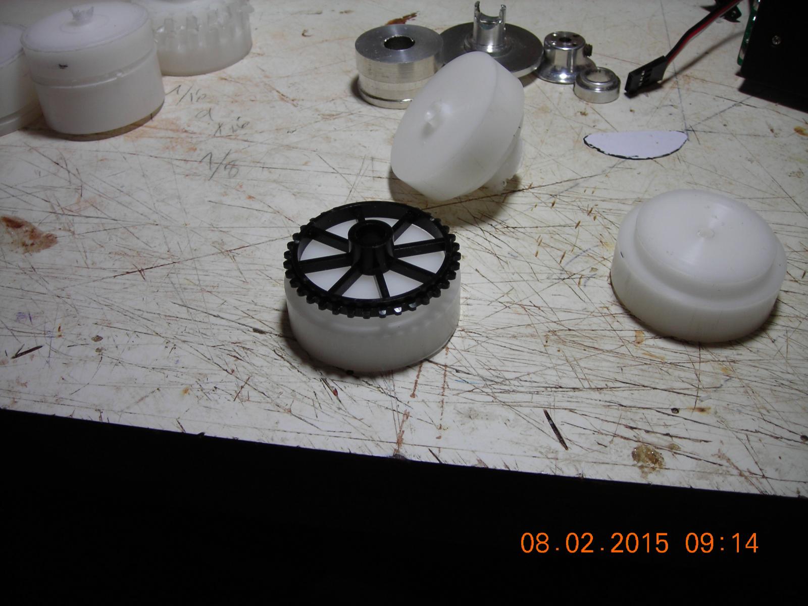
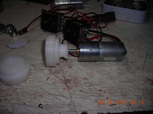
My proper sprockets arrived the other day and are now mounted on the drive discs. The discs with the raised centres will be mounted on the motors output shaft the other two will be chain driven, all the discs will act as thrust surfaces and guides for the oar racks . Still some fine tuning to do to the drive discs and I need to alter the motor board to make the best of my oars range of travel.


-
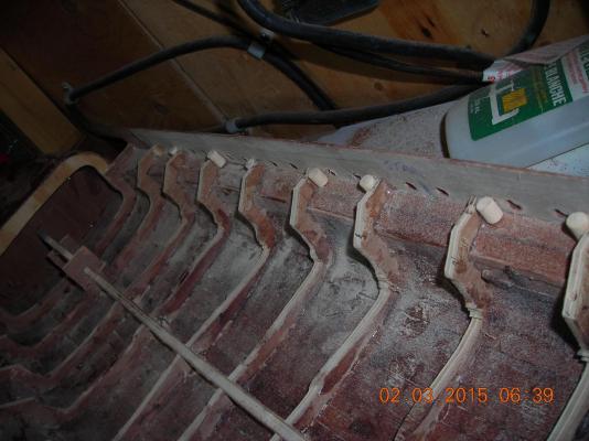
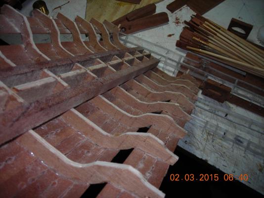
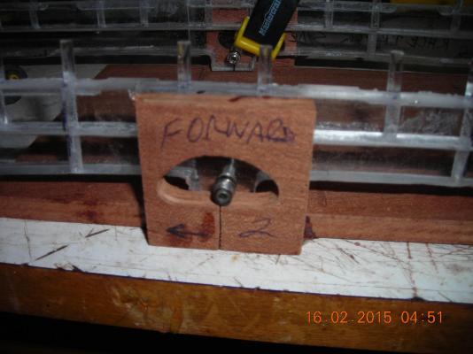
The oar racks in place and the one picture shows the guide bearing as it sits in the racetrack when it's done that bearing will follow the inside contours of the racetrack.
-
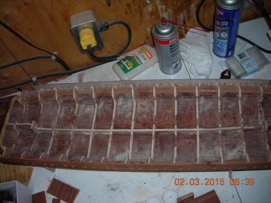
Racetracks glued into position on motor board and motor board temporarily placed in hull.
-
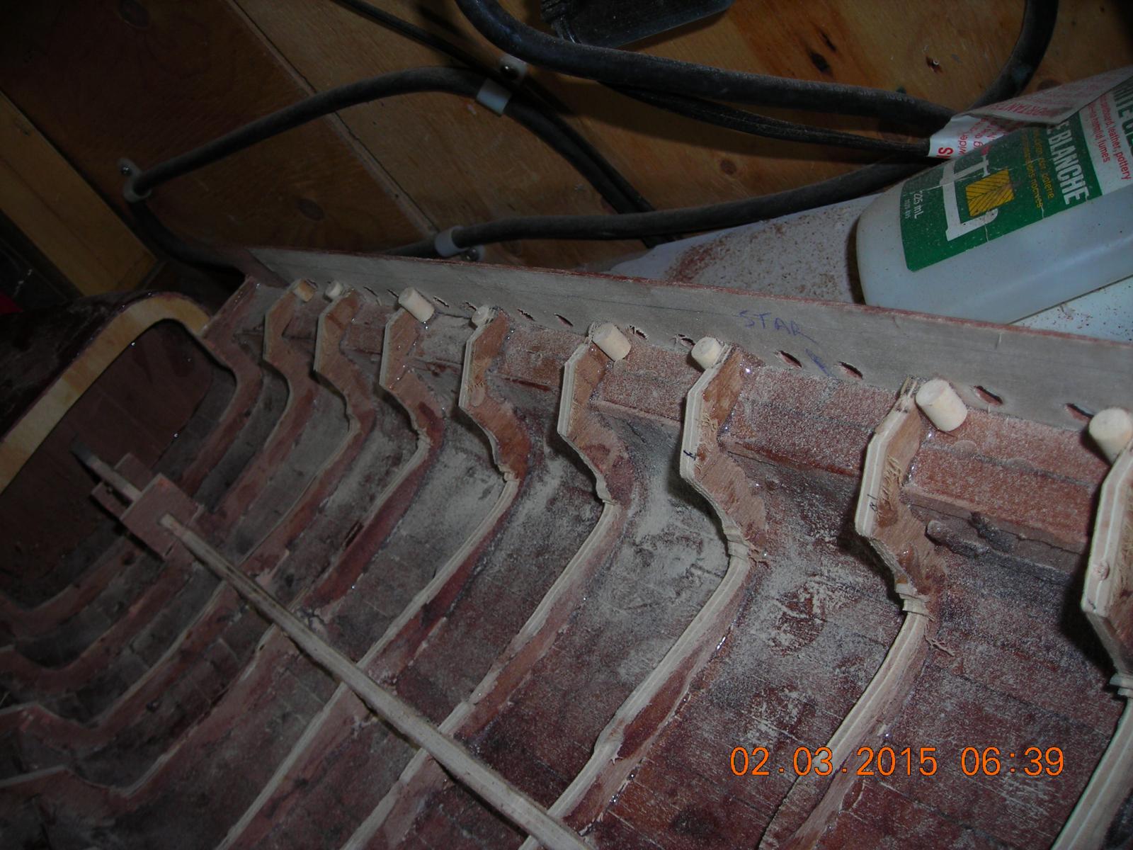
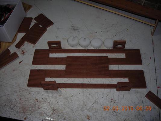
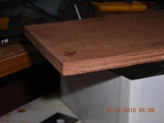
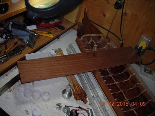
My homemade African Sepili hardwood plywood of which I have started cutting my oar mechanism "race track".

-
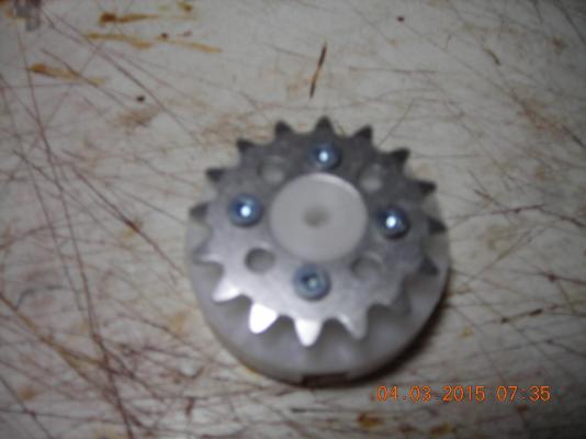
These sprockets are not positive enough so I have ordered better ones.
-
Slotting the discs and fitting the gears in place, still more to be done but I'm starting to see the light at the end of the tunnel.


-
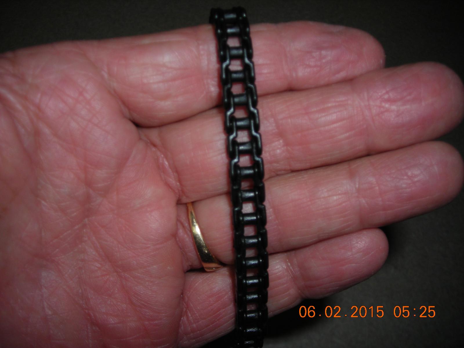
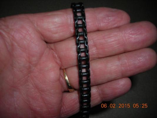
I checked out the Knex chain and see that the links are open on the bottom and could be easily pulled apart where as the ones I have are closed at the bottom which makes them much stronger. The motors are 75 to 1 ratio so there likely will be a need for strong non rusting chain.
-
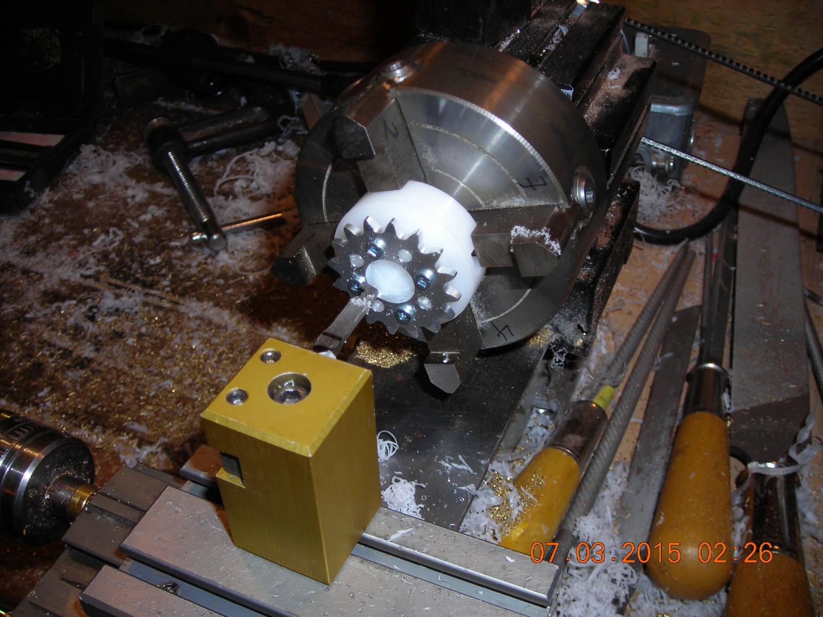
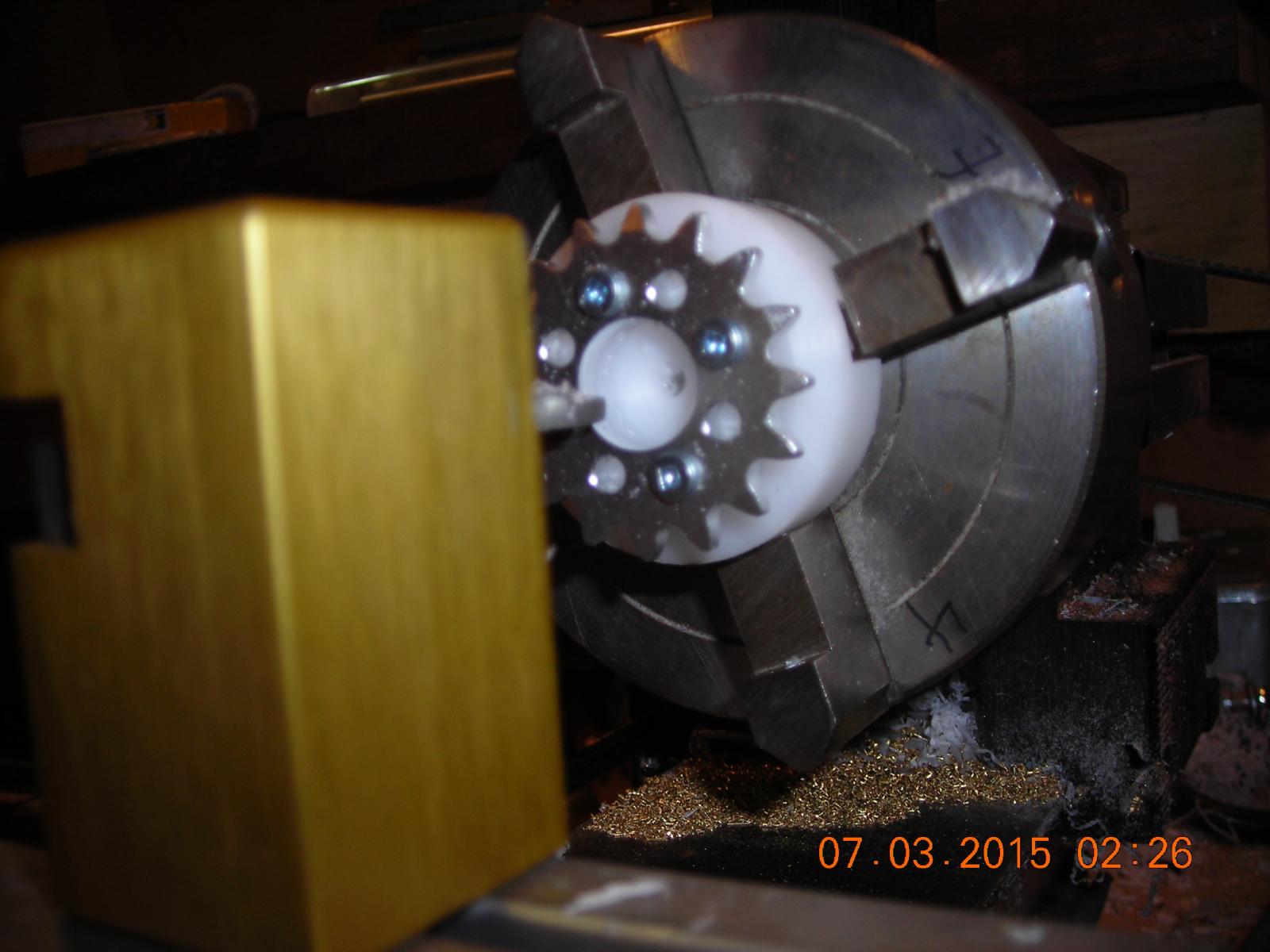
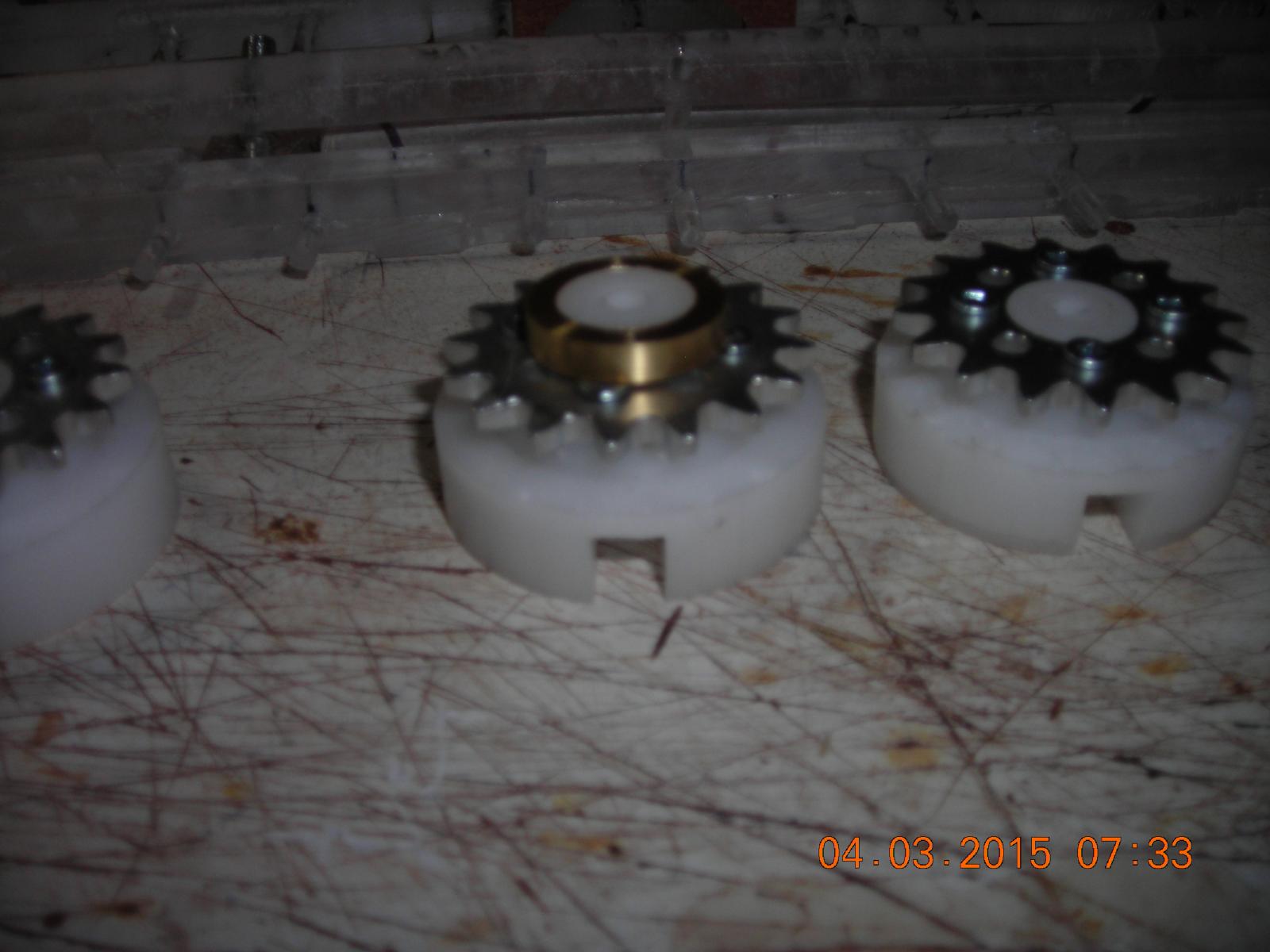
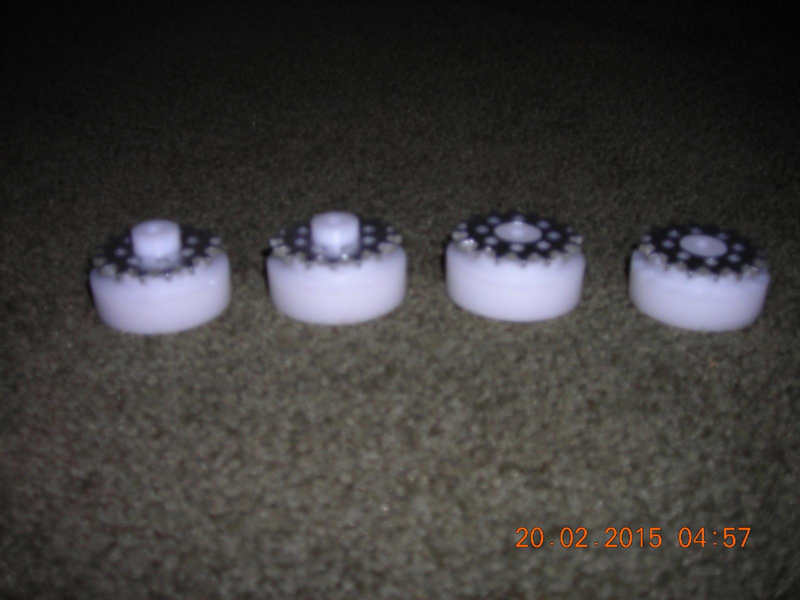
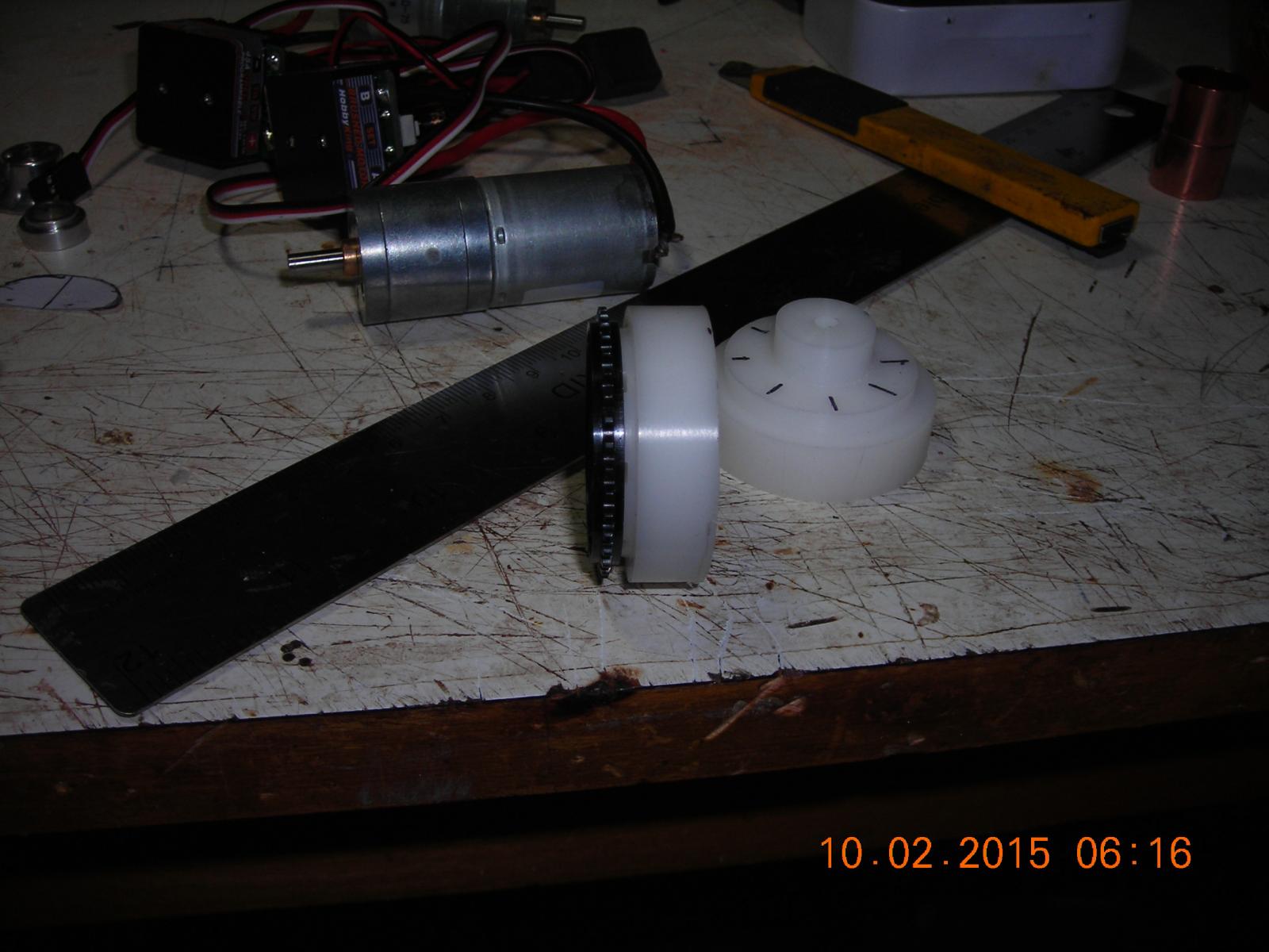
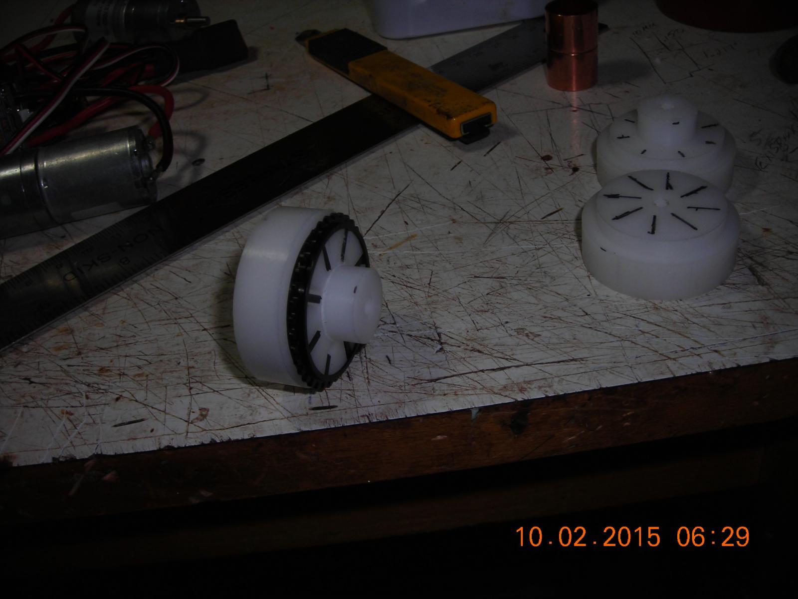
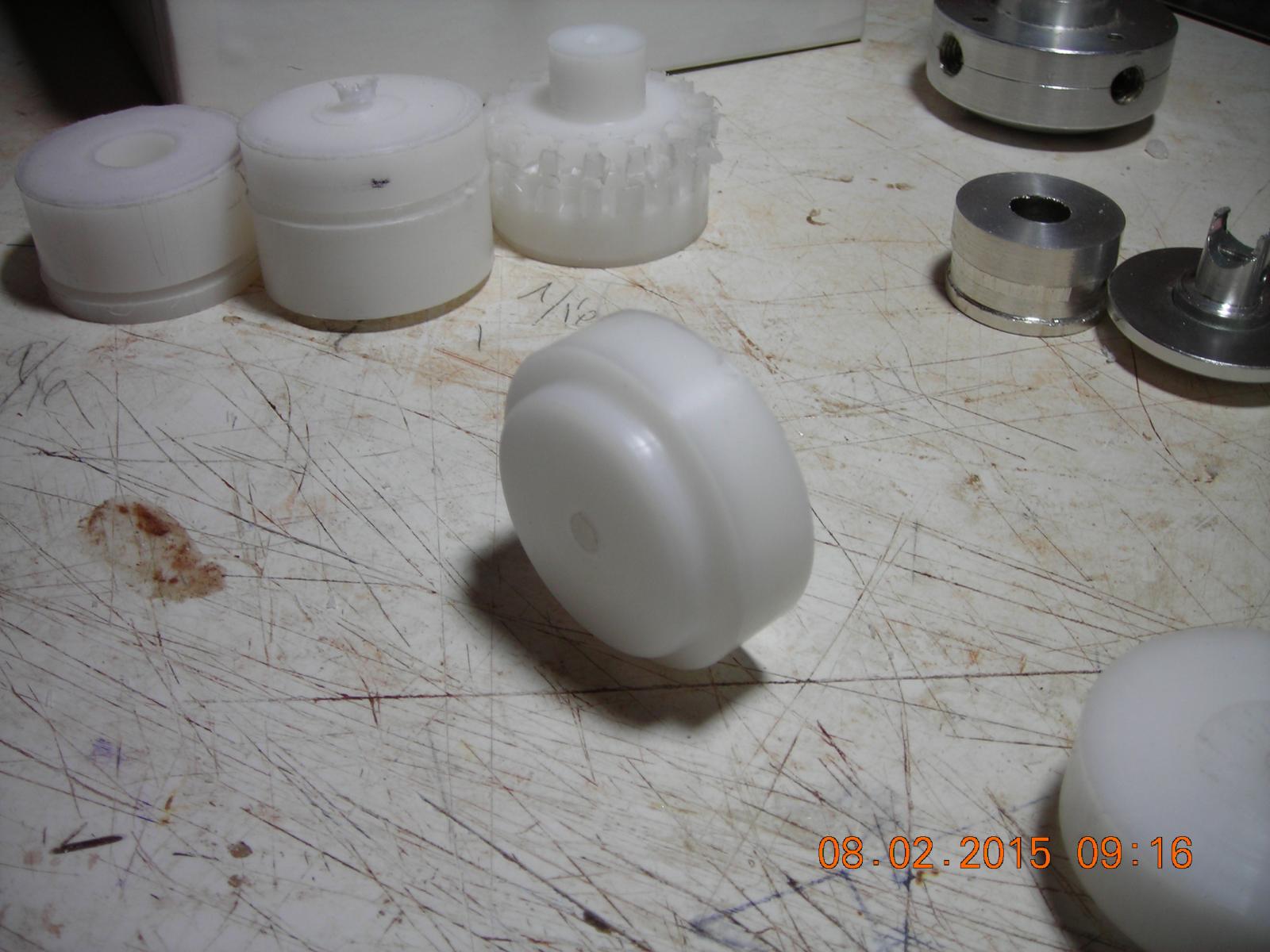
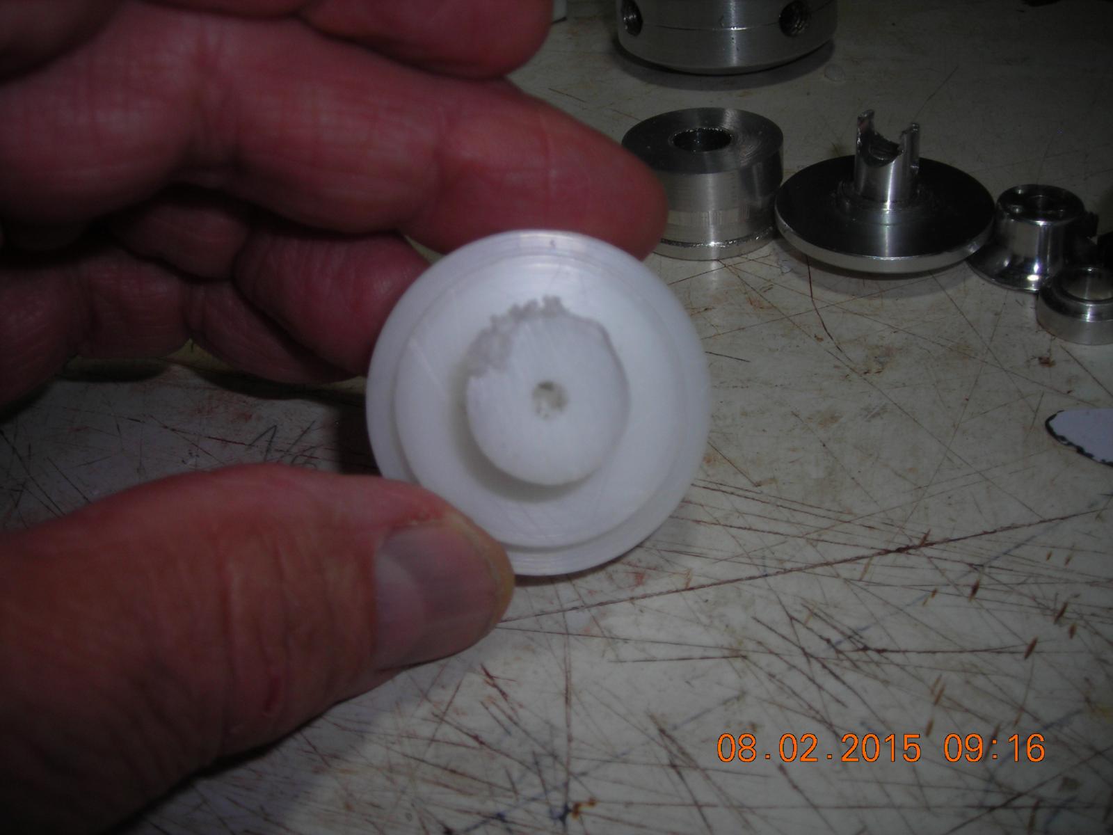
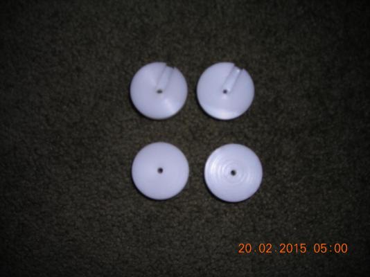
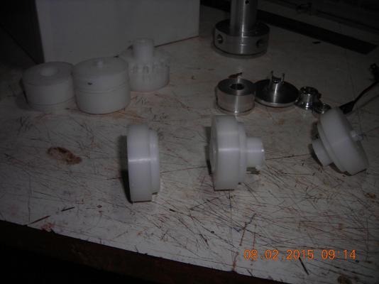
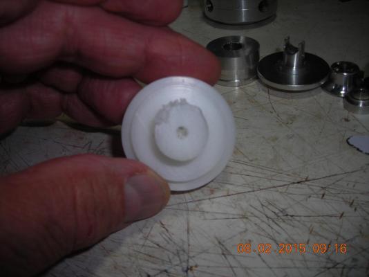
Building the sprockets, the deep ones will be motor driven the shallow ones chain driven. The black sprocket spokes will be mounted in slots I will cut in the disc faces. The opposite side of all discs will be slotted to drive the oar rack with a spring pocket to force the rack away from centre. The deep discs will have a reinforcing band with a set screw to fasten it to the motor and the shallow ones will be mounted on a bearing.


-
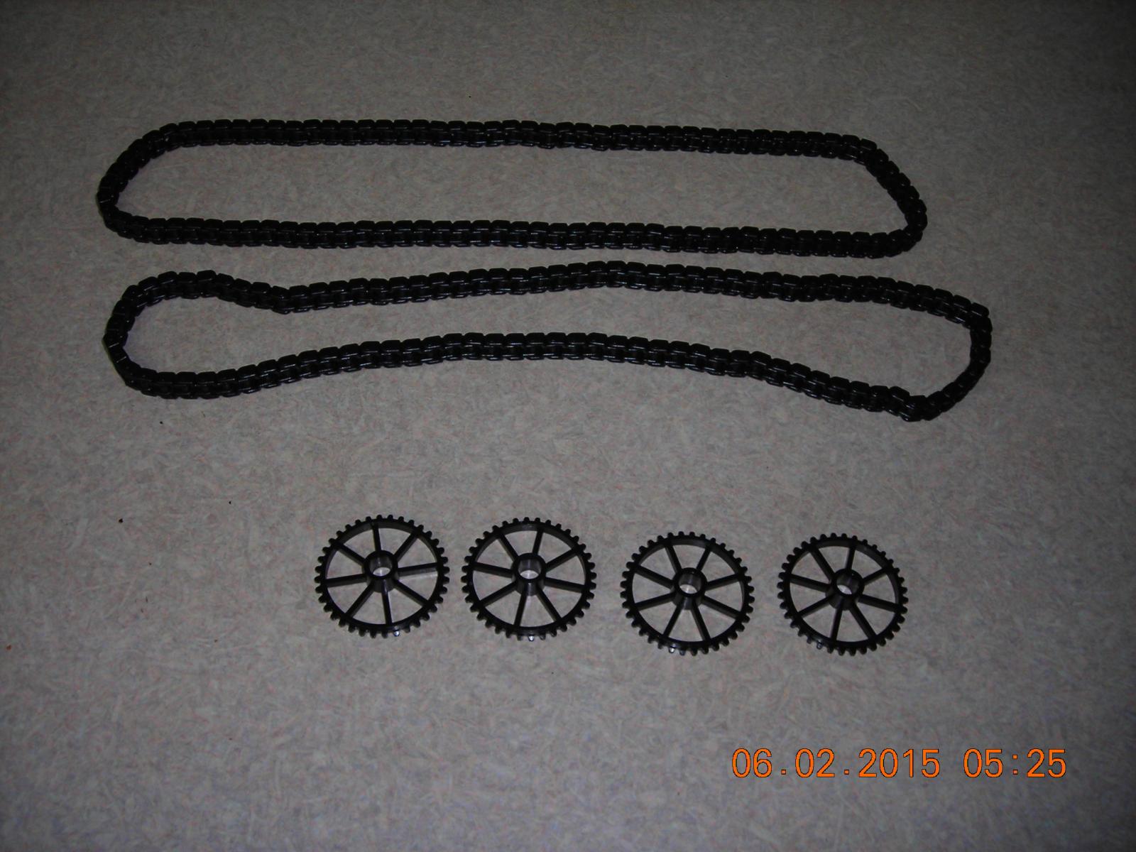
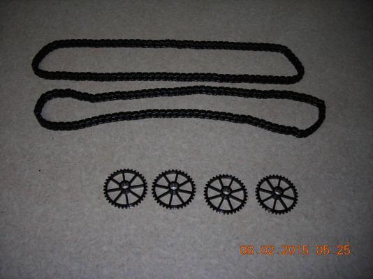
Change of plans for the drive system, originally I was going to make my own chain and sprockets but my lathe is too crude for what I need to do. I ordered sprocket and chain from Servo City which arrived today, the chain came as 196 separate links that had to be clipped together and now I can begin to make the oar drive mechanics. The is the part of the build I have been most anxious to start on and the part that is central to all my work.
-
Thanks Patrick The oar mechanism will be made to function out of the hull and I plan on making it removable for repairs or replacing parts that don't hold up. Hopefully I will have a video of it working in the next couple of months.