Foremast
-
Posts
262 -
Joined
-
Last visited
Content Type
Profiles
Forums
Gallery
Events
Everything posted by Foremast
-
Coca by Foremast - Amati -1:60
Foremast replied to Foremast's topic in - Kit subjects built Up to and including 1500 AD
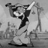
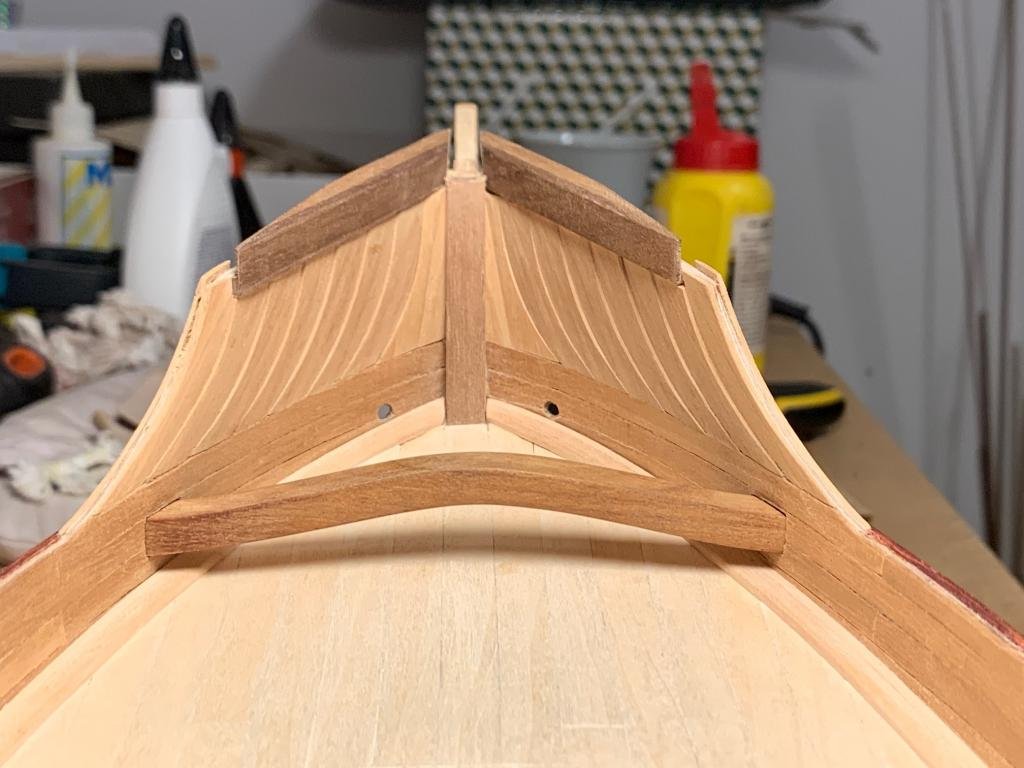
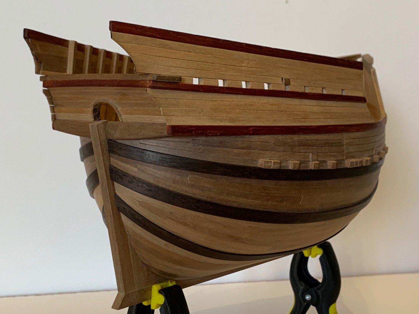
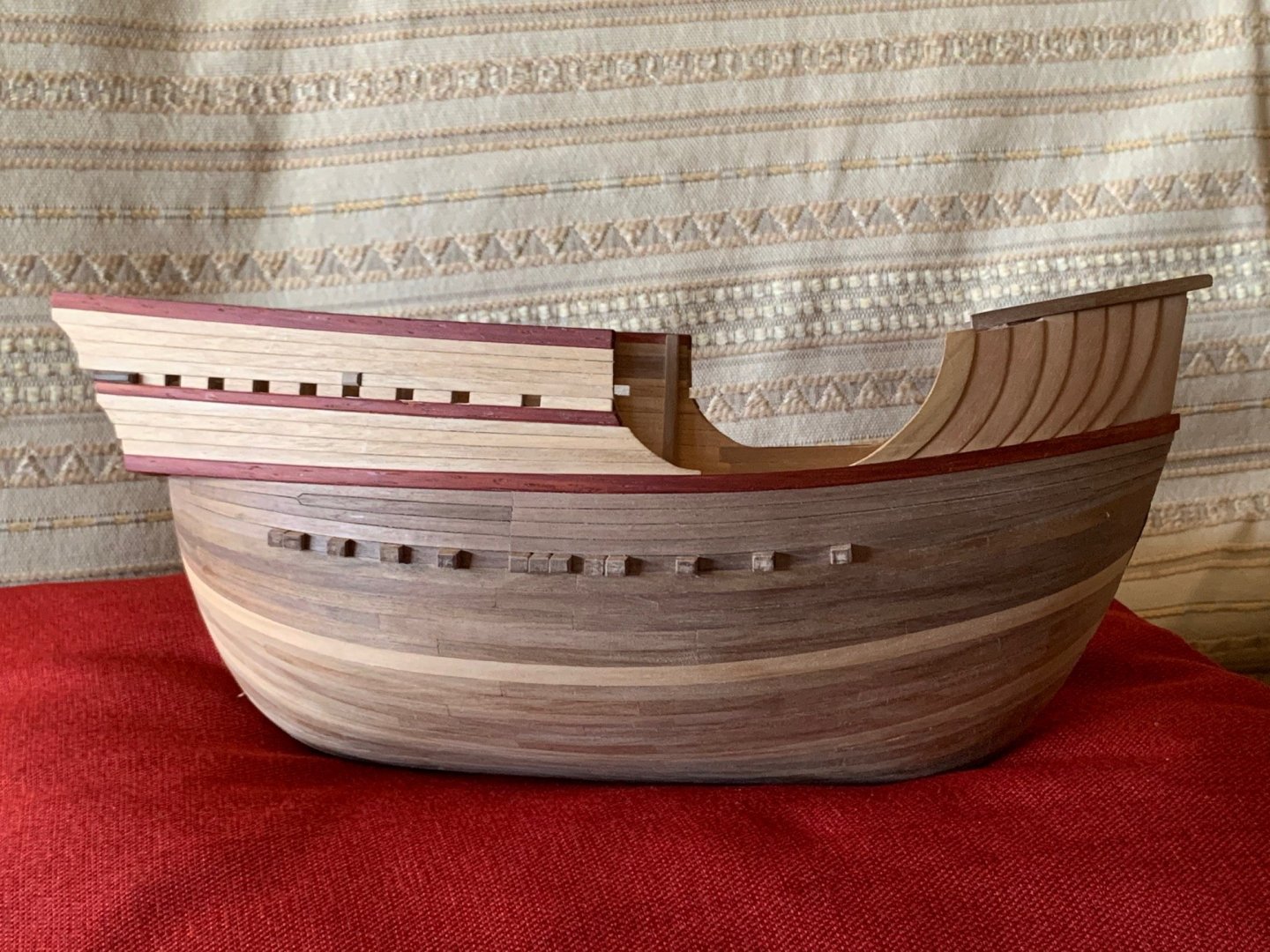
Another step in my shipyard. Now the main deck is planked and the ship has its knee of the head. Also done: hawse holes and scuppers. Last work, the big bitt under the forecastle; I made it by carving a piece of walnut - real walnut wood, not tanganika or mansonia. Cheers Alex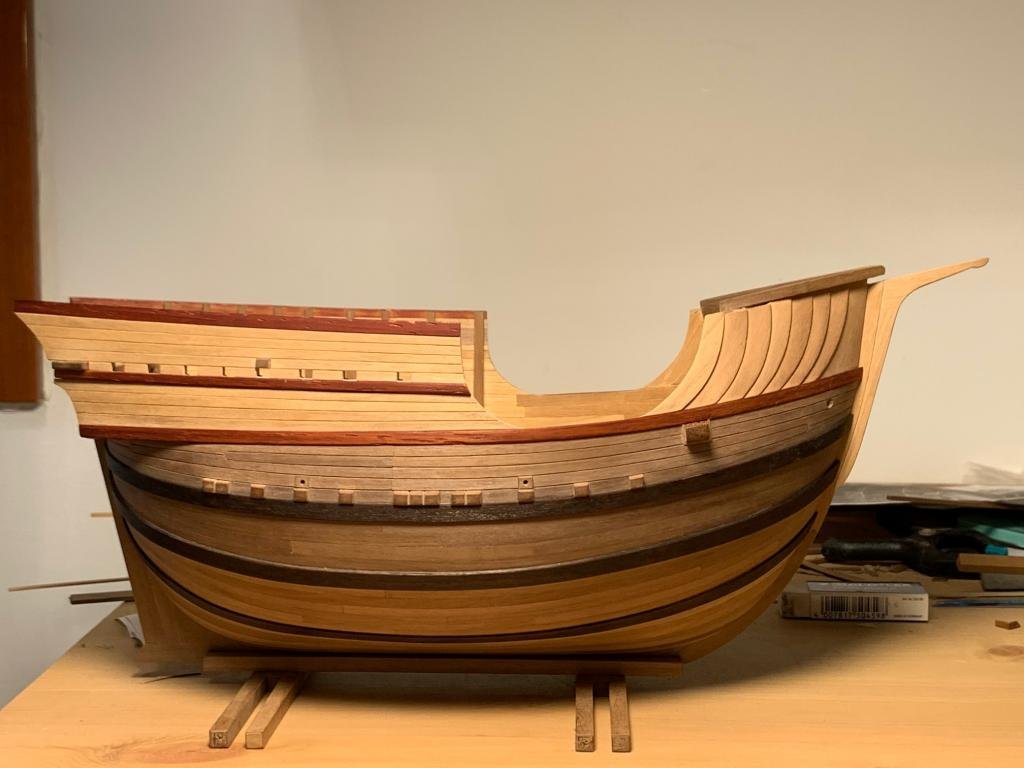
-
Coca by Foremast - Amati -1:60
Foremast replied to Foremast's topic in - Kit subjects built Up to and including 1500 AD
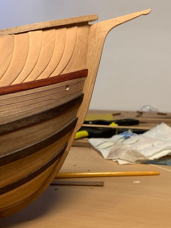
The wales are dark brown tainted. I’ve stained with wengè mordant- two hands. I have to correct my previuos message about ancient terms. I've found a precisation: - amante = each rope that is connected to the yard, to lift it; they were two (plural: amanti), coupled. So, you're right in your drawing. The term comes from ancient galleys - so was named the rope that raised and lowered the yard - riza (rizza) = rope destined to secure a mobile load. In your drawing, correct: the "rize" (2 - plural) are just hanging the yard and connected to the "amanti" - drizza = the running rigging that raises the yard. The term, properly, indicated the rope between the ramshead and the knighthead. Usually, the word "drizza" indicated both "amanti" and "drizza" (so specificated), all together. -
Coca by Foremast - Amati -1:60
Foremast replied to Foremast's topic in - Kit subjects built Up to and including 1500 AD
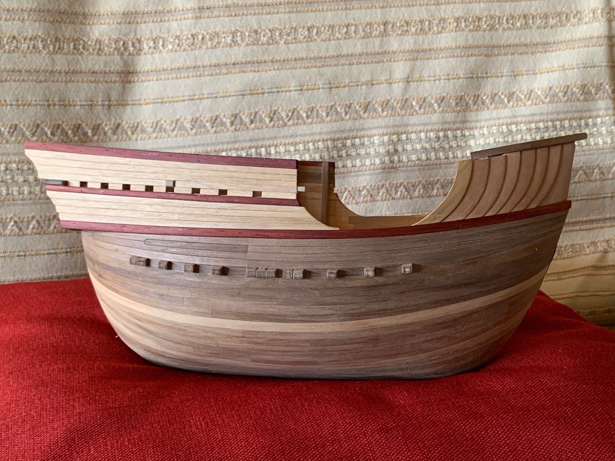
As said, Im not a sailorman so I've searched something. In modern naval Italian, the word "rizza" (noun very close to ancient italian "riza") is a rope destined to secure a mobile load, and usually equipped with a turnbuckle; and the word "drizza" (noun very close to "riza" too) is the halyard, wich is a specific - well identified - "rizza". In modern naval Italian "amantiglio" - plural: "amantigli" (noun very close to ancient "manti" and "amanti") is the running rigging that hangs a flagpole. In my opinion Bellabarba's "riza" is the halyard. And his "manti" (that's a plural noun) are the lower lifts. Little progress. Wales completed, with a little change of idea: the first wale is black, not red as previuos thought
-
Coca by Foremast - Amati -1:60
Foremast replied to Foremast's topic in - Kit subjects built Up to and including 1500 AD
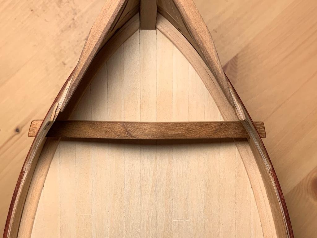
thanks to you, Waldemar for the study. I'm thinking to something similar, without temporary splicing. I'm also still in doubt about the knighthead but in the end I tink to place it Another little step. Keel almost completed and temporary placed, aiming to the the wales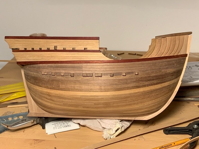
-
Coca by Foremast - Amati -1:60
Foremast replied to Foremast's topic in - Kit subjects built Up to and including 1500 AD
Now I’m fighting with the keel and wales. I hope to win soon, it’s hard! -
interesting model, Bob. A bit of patience and the shipyard will start Alex
-
Coca by Foremast - Amati -1:60
Foremast replied to Foremast's topic in - Kit subjects built Up to and including 1500 AD
at all, Waldemar. It's all on theme. It seems halyard ties should pass through the calcet, as shown in fig.17 of your message #67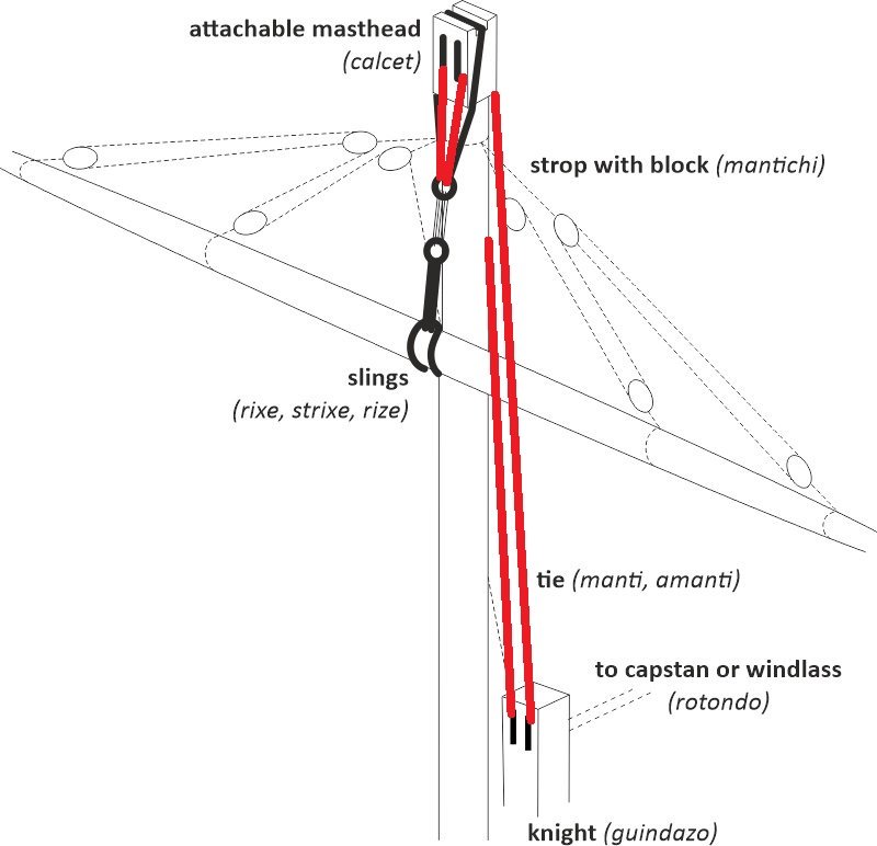
-
Coca by Foremast - Amati -1:60
Foremast replied to Foremast's topic in - Kit subjects built Up to and including 1500 AD
Very interesting. All this opens another question. If a single capstan is placed on the main deck, back the mainmast, the problem is: where are the riggings tied? We can lock them in rings on the deck, into blocks linked to those rings (I think this is more probable) or using a fife rail; in any way, it's difficult to imagine all those fittings on the main deck ... seeing the position of the mast, that's partially inserted into the halfdeck (for this, it's hollowed) and the mainmast's back area is under the halfdeck. All these fittings perhaps had to be on the upper halfdeck, unless they decided to place in the fore area of the main mast (but it would be very strange, with a capstan on the back) rings and blocks for the locking of the riggings. I'm not a seaman, and all this is free reasoning, so I join Wandemar in asking comments -
Coca by Foremast - Amati -1:60
Foremast replied to Foremast's topic in - Kit subjects built Up to and including 1500 AD
Thanks for the info. I think all configurations you have shown were applied, depending on the tonnage (so by the weight of the yards) of the ship. In little northern cogs you could see even the tie linked directly to a very simple windlass. -
I saw your photo of a sailor replica (post #65) so I have just offered myself as a part of the crew ! Alex (edit) it was a joke, of course😉
-
Great work, Christos. I think it was impossible - at the time - to make all oars the same. So little differences add realism to the model. About the replica: if you need oarsmen, whistle to me. Cheers Alex
-
Coca by Foremast - Amati -1:60
Foremast replied to Foremast's topic in - Kit subjects built Up to and including 1500 AD
You've a PM, Steven! Thanks a lot for your help. Little progress in my work. Completed planking - it is currently only roughed and needs to be filed properly; as you see at the edge of the hull's shape, there are some inaccuracies. Next step, the placing of the wales (their position is marked by oversized light brown planks) and the keel (into the fissure) Cheers Alex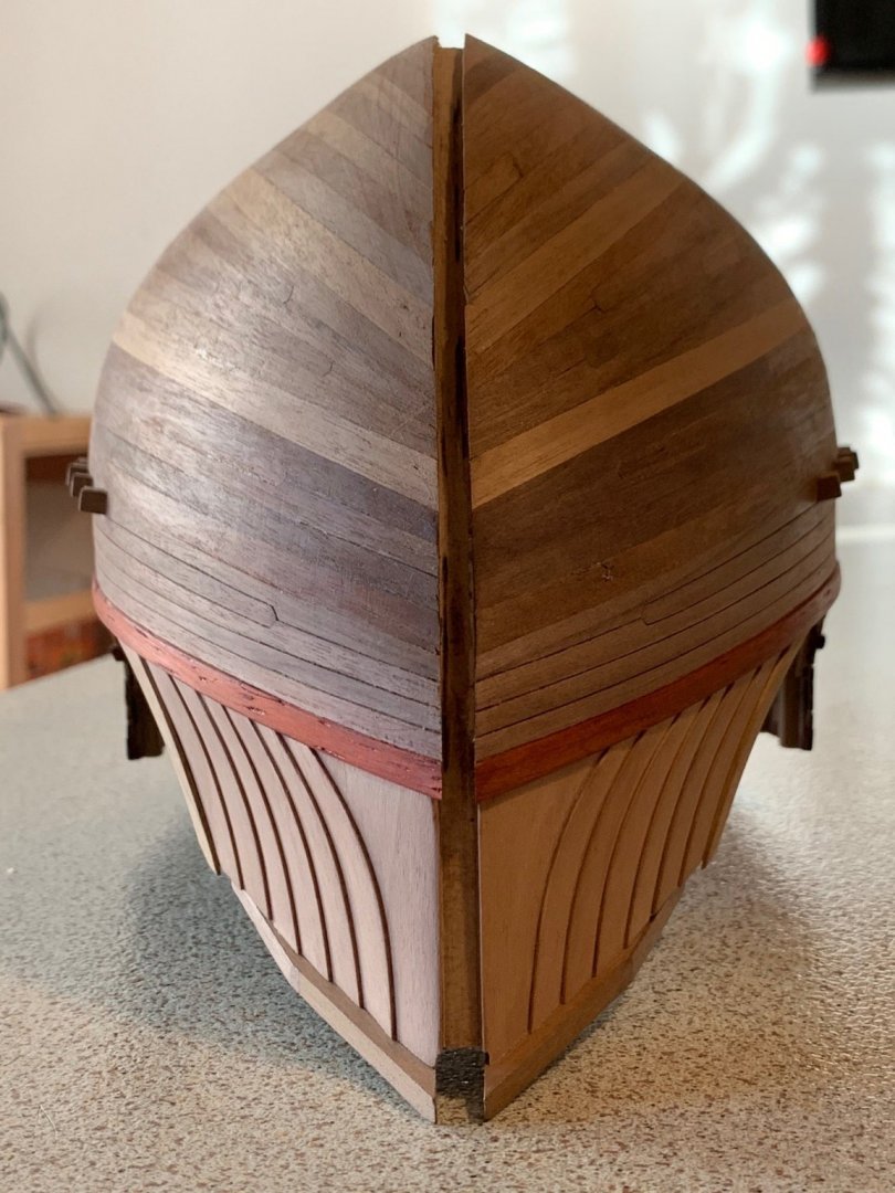

-
Coca by Foremast - Amati -1:60
Foremast replied to Foremast's topic in - Kit subjects built Up to and including 1500 AD
Thanks, Steven! Now I have something to read .... -
Coca by Foremast - Amati -1:60
Foremast replied to Foremast's topic in - Kit subjects built Up to and including 1500 AD
Thank you, very useful! My next model will probably be a Venetian cog. After all this training , no fear -
Coca by Foremast - Amati -1:60
Foremast replied to Foremast's topic in - Kit subjects built Up to and including 1500 AD
For sure. I’m trying to remember where I saw them. It seems to me in an old publication of Verlag Hinstorff- Rostock. It’s been a long time -
Coca by Foremast - Amati -1:60
Foremast replied to Foremast's topic in - Kit subjects built Up to and including 1500 AD
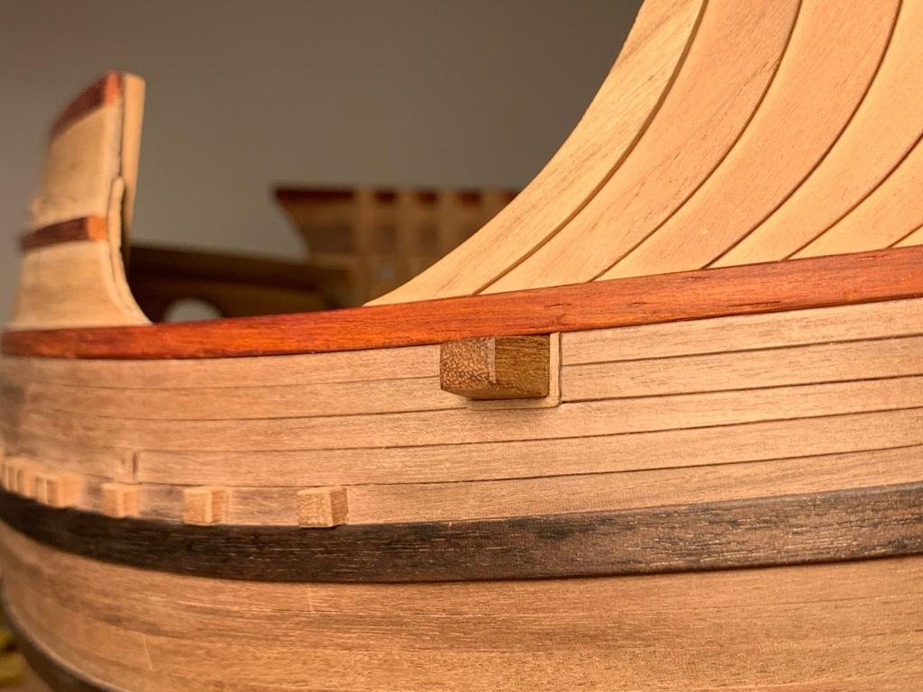
I saw them years ago in a model. A sort of removable cleats. In those points, I think, to keep anchors in position -
Coca by Foremast - Amati -1:60
Foremast replied to Foremast's topic in - Kit subjects built Up to and including 1500 AD
Thanks, Ab for the clarification and the correct assessment of the matter. At this point, everything I do I'll do it serenely. I think I'll put a big block on the halfdeck for the main yard tie, instead of the knighthead, finding it more realistic: a knighthead is perhaps too much refined for the era and this kind of cargo; and a small capstan too, on the halfdeck: I've some dubts left, but it has sense, is choreographic and its realisation is a challenge in the challenge. In the end, I'll put even a windlass - beneath the halfdeck: having eliminated the pole of the knighthead I'have space enough. Hello, Popeye! Nice to see you here! I prefer the scratch building, but I had only a little time so I bought a kit. Despite the quality of the manufacturer, I'm not satisfied (I'm a free spirit and try to understand things before do them, whereas a kit can keep a modeller in chains, really) so I've been changing a lot ... till the point that ... if I had built the ship since the beginning using only the drawings , now I'd be much ahead wit my works. Waldemar, this of ours is ... a sort of research! Not destined to become famous, nor referred to a important vessel but it can help us or others to satisfy their need of knowledge and make a better model! Cheers, friends Alex -
Coca by Foremast - Amati -1:60
Foremast replied to Foremast's topic in - Kit subjects built Up to and including 1500 AD
Thanks for your analysis, it confirms that rear the mast there was always something to lift the yard. If it was placed on the main or half deck (or both) is still to investigate; where the solution depended in the end only by the shipwright's project. I don't think the main yard tie was constantly coiled (this is a solution that I saw in little northern cog, in which there was no knightead and the tie run from the top directly to the windlass or to the windlass through rings on the deck). Once in position, I think the yard was hanged to the mast; and the main yard tie ... tied to a cleat, using at this point the winding gear for other purpose. Knightheads had often one or more cleats, on the side. -
Coca by Foremast - Amati -1:60
Foremast replied to Foremast's topic in - Kit subjects built Up to and including 1500 AD
Why create a new topic when this is already on the right track? After all, I love mess! I hope everyone interested come here and mess up all our reasonings, so to write a new page of this model. Feel free to write whatelse you think. Mataro cog lacks of many superstructures. But a few points should be considered, before asking to ourselves how many (and which tipe of) winding gears could be present. - It is not possible the mainyard could be lifted pulling the rope whith hands only. It was too heavy and the space was too little to do it, on the deck or on the halfdeck, was the same. Somewhere, a gear had to be installed. As well, somewhere a kinghead or a block had to be installed: the rope which pulled the yard had to pass through a device. A device with pulleys, to reduce the effort. - It is not possible the arrangement of ropes shown in the model. Every rope couldn't be pulled directily by the crew from top to down and simply wrapped to the railing. Ropes had to be pulled from bottom to up and turned through a block or a ring placed on the deck, then hanged somewhere (included railings) or - why not - let on the deck, once tied to a ring or on the rope itself. Somewhere, blocks or rings had to be present on the deck, close to the mast. Now, your question: does it exist a single position where a single winding gear could lift yard, goods and anchors? Perhaps yes, if the hole in the halfdeck is the passage of the main yard's rope, and a block is installed on the main deck, rear the mast and forward the winding gear. It's difficult to imagine a kinghead in this configuration and it's also difficult to imagine a capstan: too much interference with the tiller. The device should be a windlass. Perhaps not, if we want to follow till the end the strange configuration shown in the model (the main mast placed in the main deck but the manoeuvring positions on the upper halfdeck - this is the real origin of many complications). This needs all systems on the halfdeck, including a winding gear. In this configuration we can imagine either a kinghead (passing through the hole near the mainmast - as supposed by Winter and Landstrom) or a block (in the same position: the hole could be just the effect of its ripping). All this needs a winding gear on the same deck; a capstan, probably, less bulky. This also need a secon winding gear for anchors and heavy goods. This is only my thinking, no claim of thruth, obviously -
Coca by Foremast - Amati -1:60
Foremast replied to Foremast's topic in - Kit subjects built Up to and including 1500 AD
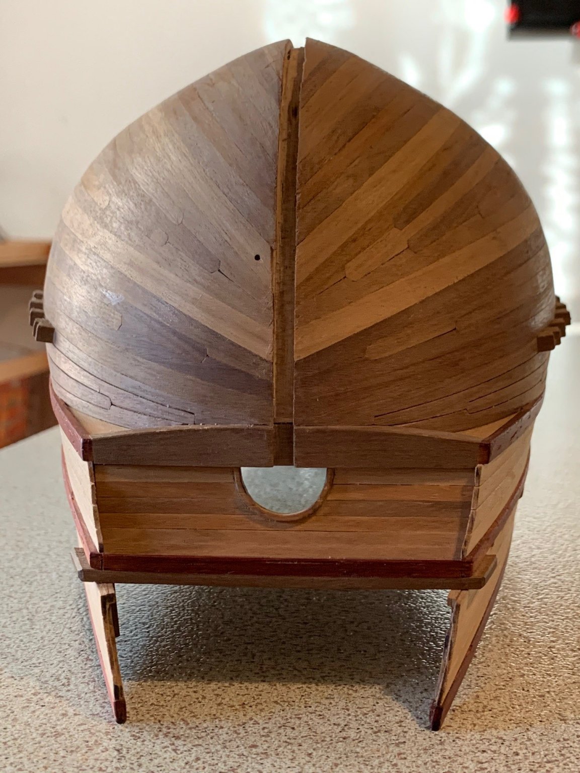
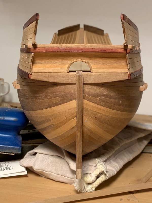
You've hit the mark, Ab. Thanks for the very interesting notation. I'm trying (also Waldemar, I'm sure) to imagine how the crew could work on that kind of ship, lacking lots of clues about the internal fittings. I think, the hole on the quarterdeck - circled in red - could mark the position of a capstan and now your notation confirms me that it's possible: through the hole could pass the rotation pin, and beneath (clamped to beams) there was a support tightened to the upper part. Now has its sense the strange-shaped, holed piece of timber that lays on the rear deck of the Bremen cog, shown in the post#17: it's the upper part of the foot, intended to be clamped underneath with another similar wooden board. A heavy block simplifies a lot the fittings and clears out a lot of space. Now a new question: how could the crew rise up to the upper decks? I thought through ladders in correspondence of the holes - circled in green - but not excluding pegs fixed to the side - circled in yellow. In the forecastle, I'd exclude a bowsprit, the hole - blue - suggest a ladder. Thanks for the attention Alex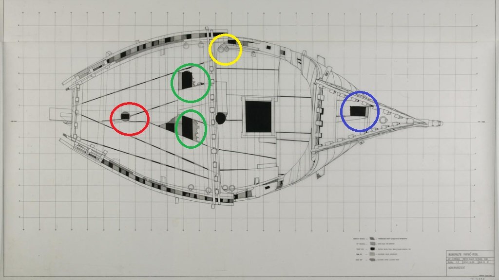
-
Coca by Foremast - Amati -1:60
Foremast replied to Foremast's topic in - Kit subjects built Up to and including 1500 AD
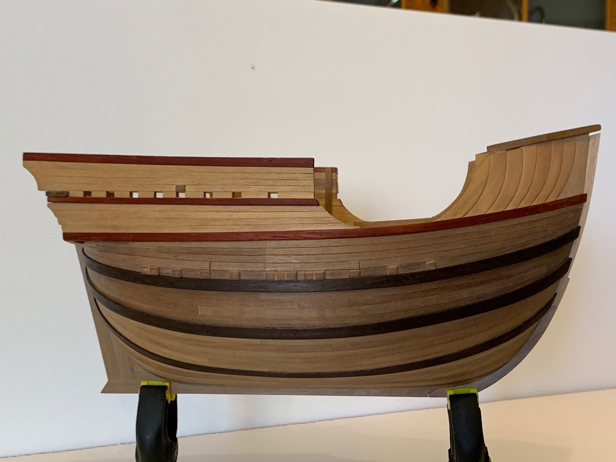
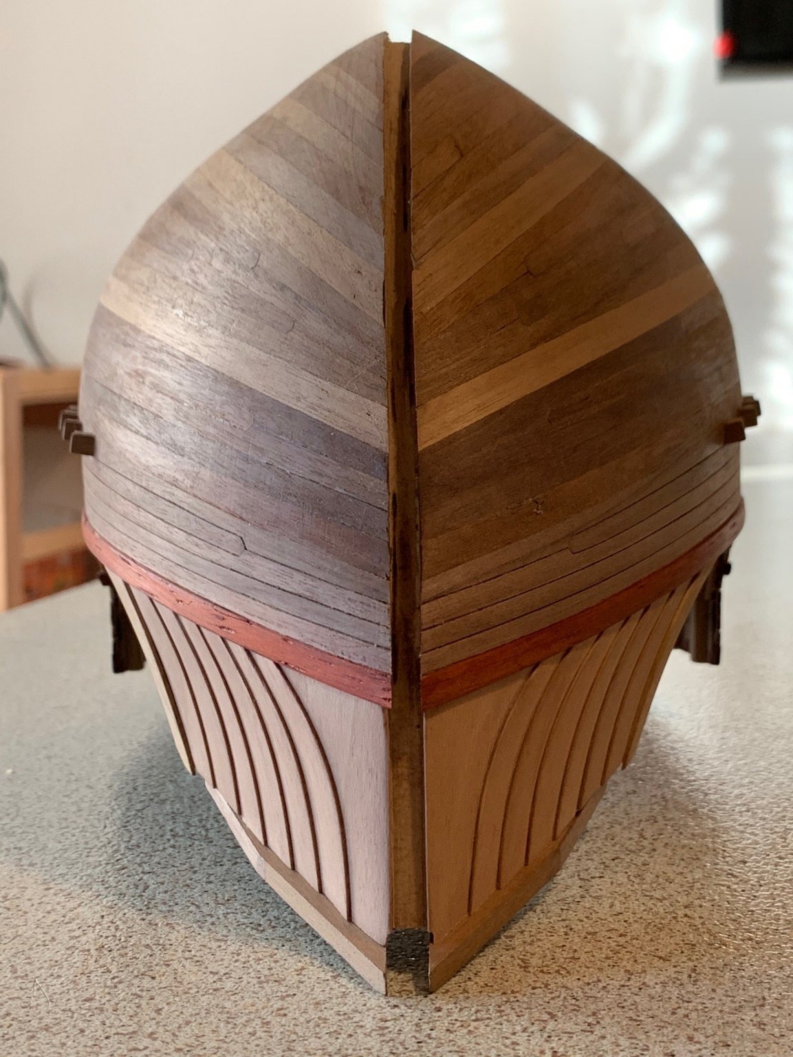
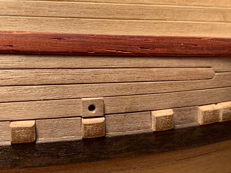
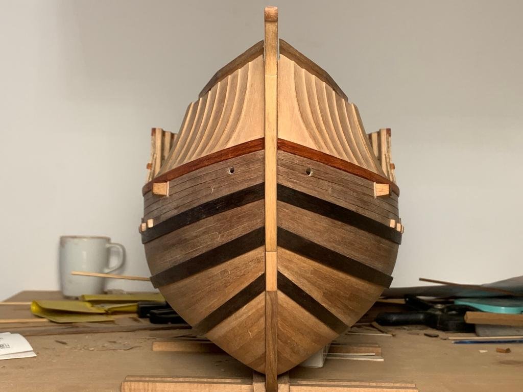
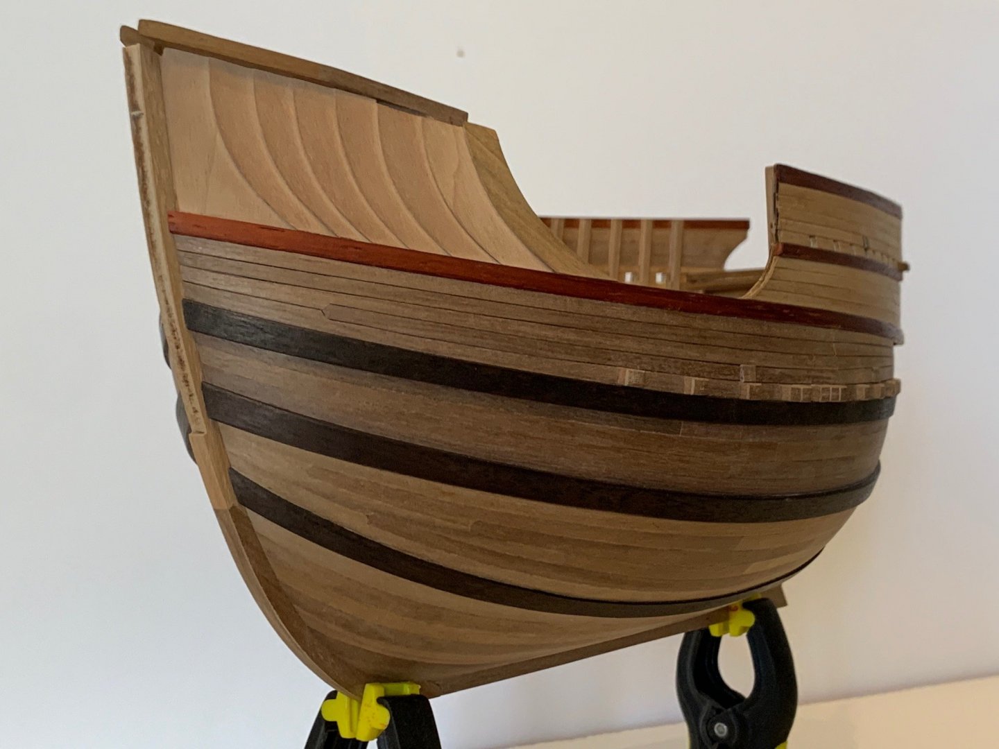
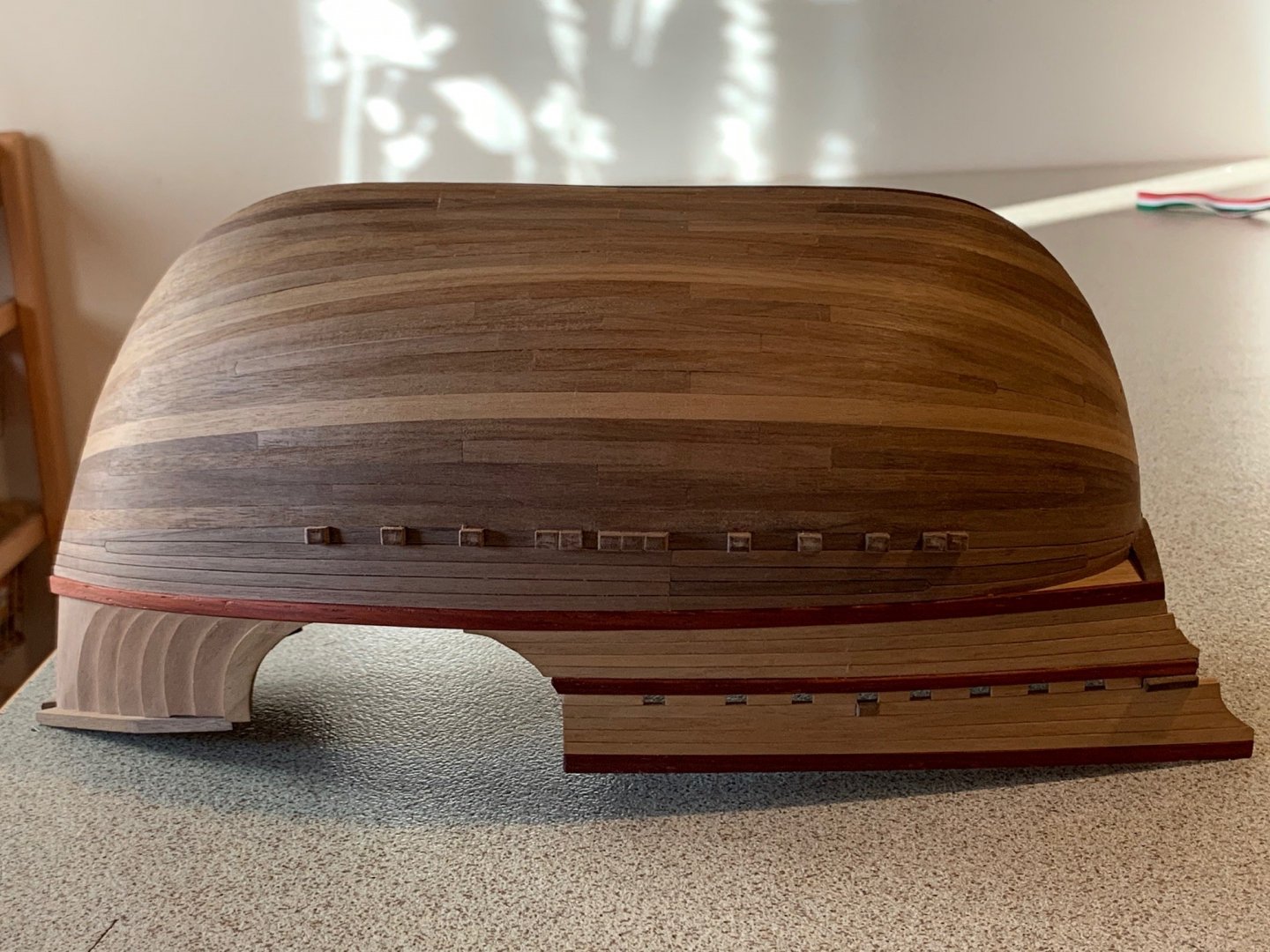
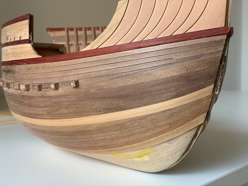
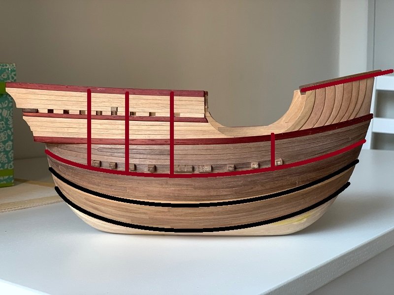
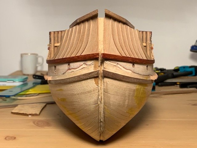
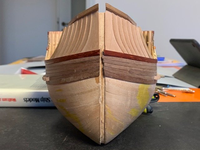
Fifth and last step. Planking of the second section of the hull and the third one of the right side. Every section will be completed by doubling the terminal laths, to make the sheer strakes. First section: ends just beneath the false beams, the overlaying lath will be red, like others. Second section: ends 4 laths under and the overlying lath will be heavy brown color. Third section: ends 6 laths under and the overlying lath will be heavy brown color as well. The cover laths will be posed over the light brown oversized ones, matching the junctions. To be sure about a good matching, the lath below is a bit thinner than that above and this one will be a bit concave on the internal side too. I've made a few drop planks to follow the accentuate bending of the sheer strakes, that I made as it results by Winter's drawings. I don't know if they are too many but at this point I had no choice, I had to reduce the planking's size from 30 mm (maximun, between the sheer strakes in the central area) to 7/13 mm (terminal, at the stern and the bow) and it was impossible to thin every strip evenly : 1-1,5 mm (gauged in scale: 6-9 cm) had no-sense. Last photo, project. End of the "flashback". From this point every update will be in real time. Thanks for your attention. Cheers Alex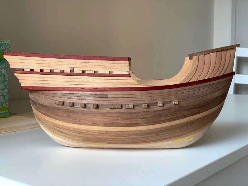

-
Coca by Foremast - Amati -1:60
Foremast replied to Foremast's topic in - Kit subjects built Up to and including 1500 AD
Fourth step. Pasted the false beams, following the bending of the deck and respecting Winter's scheme. First section of the planking posed; it's dark walnut wood made. Splicing of the strips in evidence, as in the upper part of the planking: every strip has been lightly filed on both edges before the pasting. I have slithered a cutter blade between the strips, after the bonding, to remove glue residues and obtain the effect shown in the pictures. I made a few drop planks to avoid excessive thinning of the strips at the bow and stern.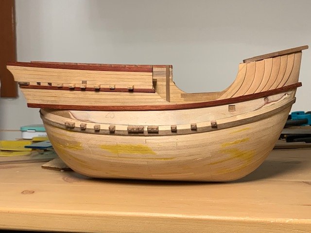


-
Coca by Foremast - Amati -1:60
Foremast replied to Foremast's topic in - Kit subjects built Up to and including 1500 AD
At this point I’ve something to think, really! Not excluded a little windlass on the halfdeck, instead of a capstan , dedicated just to the mainyard. But even this, is a Northern Cog idea 🤔 -
Coca by Foremast - Amati -1:60
Foremast replied to Foremast's topic in - Kit subjects built Up to and including 1500 AD
About the knighthead (...thanks!👌 ) : somewhere it had necessarily to be placed, because the yard needed to be lifted and kept in position. No idea if it's more plausible as placed in the upper halfdeck or in the maindeck - no hole on the deck as a clue - but I'm almost sure that a lifting device had to be placed back it. As previuos said, the mainyard was too heavy. Now, thanks to you guys, I have a monkey on my shoulder. If also the tiller is out of scale, as suggested by Waldemar, a windlass could be placed back the mast and also back the knighthead, if it's on the maindeck too; so, only one windlass could serve the anchors and the main yard, as pointed up by Patrick. Solution that out of dubt is in according with maditerranean ships of the XV century. -
Coca by Foremast - Amati -1:60
Foremast replied to Foremast's topic in - Kit subjects built Up to and including 1500 AD
No bother at all, friends! I’m here to discuss, trying to fill a bit the lack of knowledge. I consider this model a challenge and the more we investigate, the more we can find solutions. Your model will be better than mine and perhaps the next one will be even more. I’m glad to be considered a sort of Guinea pig😄 I know, Cog can’t be assimilated to Coca, neither Carrack nor generic Nao. But facing similar issues on similar ships (for tonnage and sailing), perhaps the shipwrights founded similar solutions. After all, round ships were born in Northern Europe and 1380 a.d. (Bremen cog) si not far from 1450 a.d. (Coca), neither Bremen and Barcelona are so distant, thinking to medieval trade paths. cheers Alex