DONATION DRIVE - SUPPORT MSW - DO YOUR PART TO KEEP THIS GREAT FORUM GOING!
×


johnhoward
-
Posts
162 -
Joined
-
Last visited
Content Type
Profiles
Forums
Gallery
Events
Everything posted by johnhoward
-
Thanks for the update Tim, You guys are really getting creative with the Ironclad Model crew member figurines. I'm looking forward to those other Shipcrafter Team E-Mails I have missed that we discussed today. JOHN HOWARD
-
Mamoli's Blue Shadow rigging question
johnhoward replied to johnhoward's topic in Masting, rigging and sails
test -
Fellow modelers:, II have been asked by a friend to repair the rigging for his "Mamoli" MV22 "Blue Shadow" model. My research confirms that it is a "fictional" but very "handsome" model but it seems to be over-rigged for such a small vessel and crew size during the American Revolutionary War Era. Are my suspicions correct? Specifically, would it carry all of the upper "Stun sails"? If realistic, would its' rigging be more likely to use French or British convention? Any other comments would be welcomed. Thanks, JOHNHOWARD
-
Tim, Thanks for the August 2024 update snout USS St. Louis Ironclad model. I just wanted you to know I'm still around and am presently trying to repair a model of the 1778 Blue Shadow for Jack Powell but am still interested in the progress on the museum display progress for our the USS St. Louis. I have also been continuing my research for James Eads' memoirs on then building of the "City Class Ironclads" for construction details we never resolved, but no success so far. JOHNHOWARD
-
Tim, Thank you for the continuing fantastic updates to this decade long scratch-build model and my "hat is off" to all those "St. Louis Model Shipcrafters" who have persevered thru the "Pandemic" and continued their support and modeling skills. I echo Don's recent comments on "plans for "it's public display' which we originally estimated in 2014 to be a "Two or Three" year project however, we had failed to consider the volume of a 1:24 scale model which is also"over 7 feet long", and of all the possible modeling details that could be included, plus the inaccuracy problems we discovered on the available US Park Services "USS Cairo Class" Ironclad model plans and missing data which required extensive additional research. I also want to acknowledge all of the many NRG Member contributors to our "USS St. Louis" Model Forum. JOHNHOWARD
-
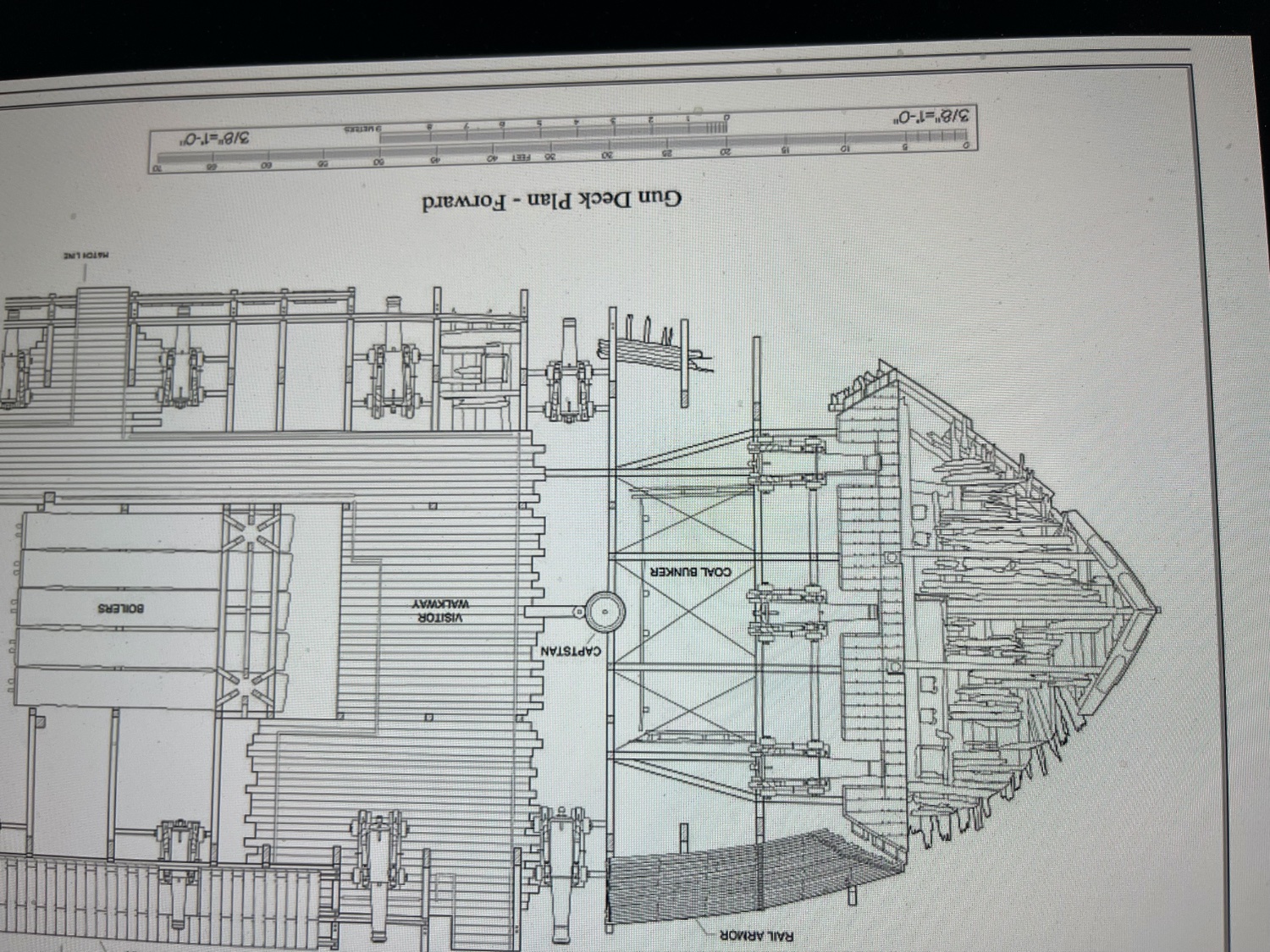
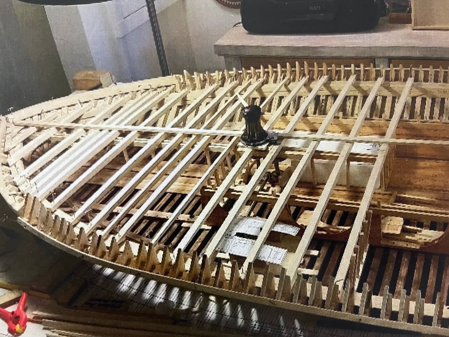
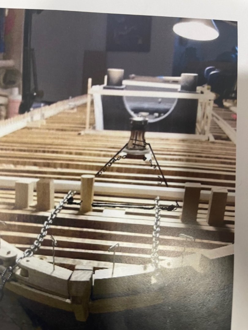
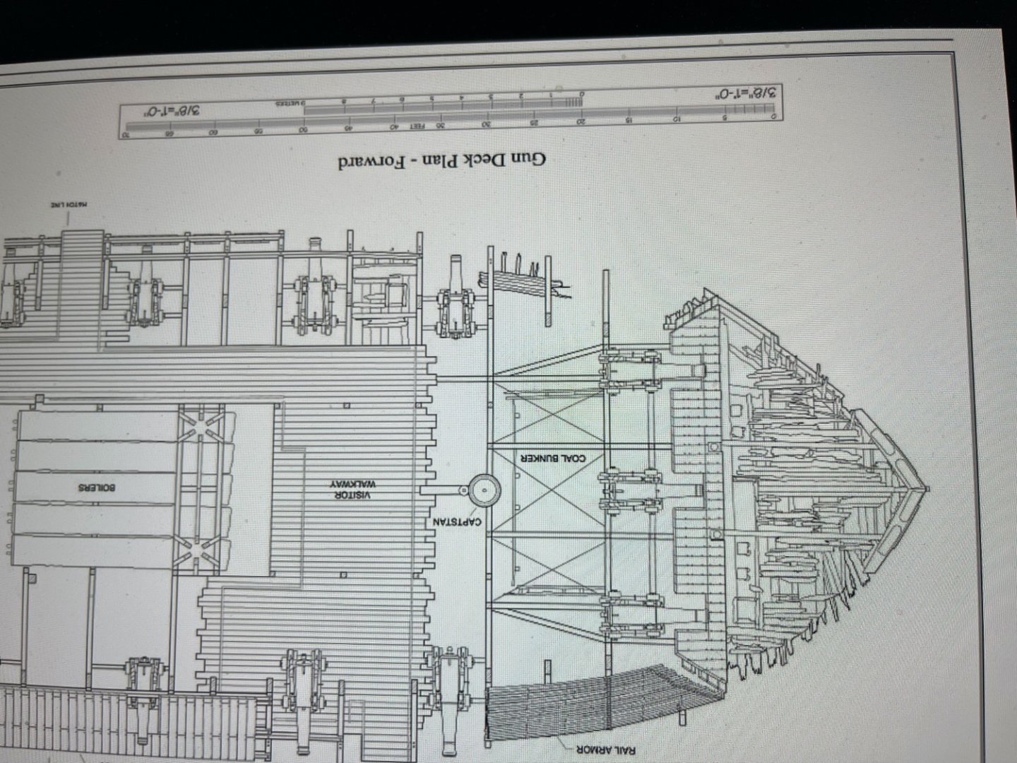
I found my photo! Attached is a "Mock-Up" photo of our "USS St. Louis" Ironclad Model Forward Gun Deck with its Anchor Chains and continuous "Messenger Rope" wrapped around the Capstan and the front casement rollers, with the anchor chain itself entering the "chain locker access door" just in front of the Capstan. Either port or starboard anchor could be individually raised or lowered by adding the "Nipper Ropes" to secure its chain to the "Messenger Rope" and then rotating the capstan either clockwise or counter-clockwise, as required. JOHNHOWARD
-
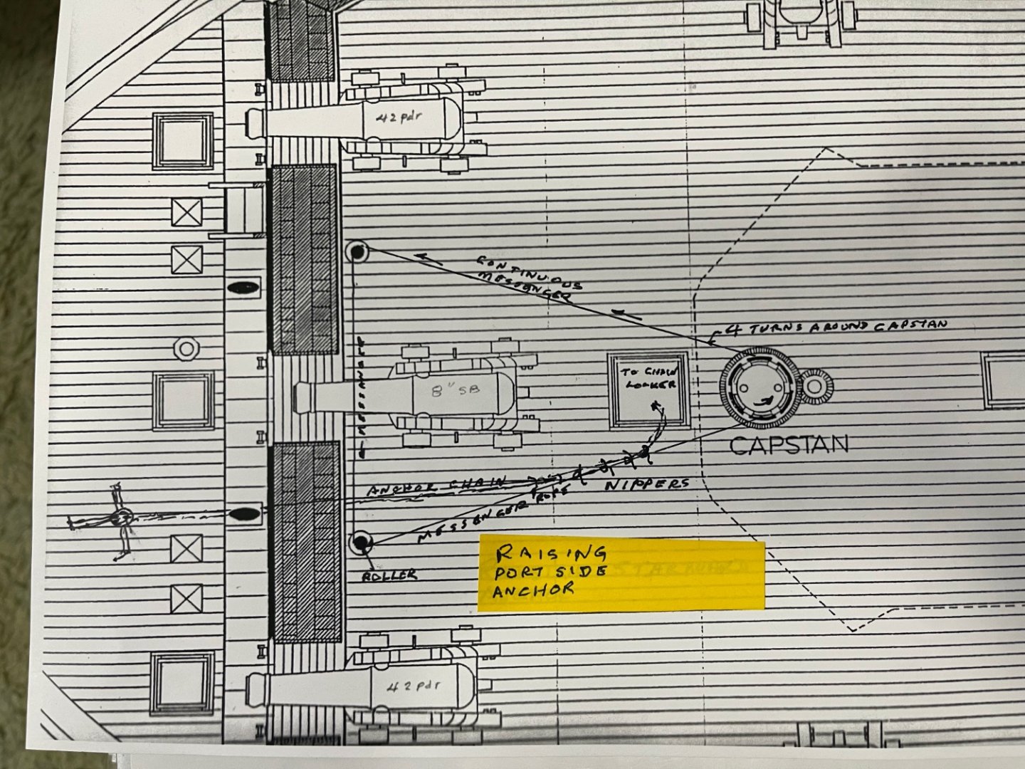
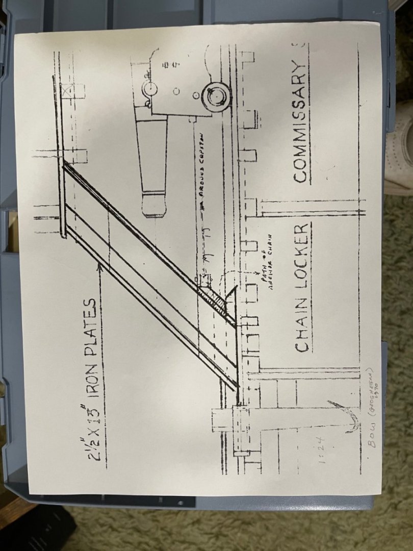
Further information on adapting Chain Linked Anchors to Rope Style Capstans such as for the USS Cairo:: The attached sketch shows how the continuous loop "Messenger" rope and "Nipper" ties were rigged to anchor chain to raise and lower anchors using a rope type Capstan on large sailing ships into the Mid-1800's. This is how we planned to rig our USS St. Louis Ironclad model. The continuous Messenger rope passes around two rollers behind the ironclad forward casement and is wrapped around the Capstan about 4 turns. The "Nippers are used to secure the anchor chain to the "Messenger" as it emerges thru the Hawse Hole in the forward casement and are un-tied as the anchor chain reaches the deck hatch above the Chain Locker for stowage. Raising the port-side anchor is depicted in this sketch. Simply reversing the Capstan/Messenger rope rotation direction will lower the port anchor or raise the starboard anchor. We successfully "Mocked-up" this arrangement in Mid-2018 but unfortunately have mis-placed the photograph. JOHNHOWARD
-
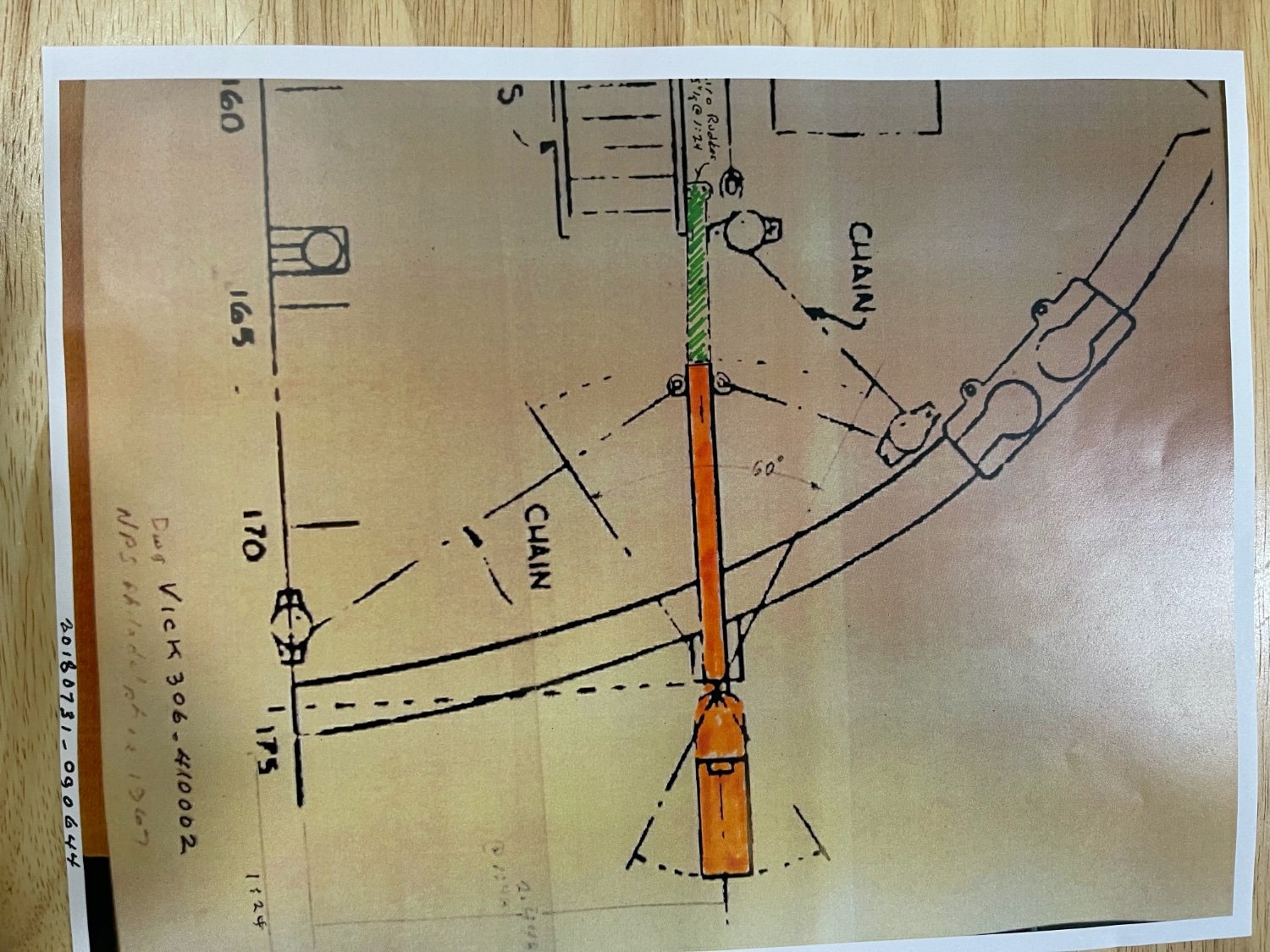
Brian and Roger, As a follow-up to our discussion on rope vs chain for the City Class Ironclads: Brian's Posting #285 mentions the use of a "Traveler or Carrier" loop of rope around the "Rope type Capstan" which then was temporarily incrementally tied and untied to/from the anchor chain to raise/ lower the anchor. This was a standard practice on large sailing vessels of this time period. I believe this is exactlly what they did on the Ironclads. We had planned to use this method on our USS St.Louis and had "mocked it up," but I couldn't find our photograph of it. The attached photograph is a section of Geoghegan's drawing cross-section of the forward casement which includes a small pulley for the carrier loop and the anchor "Chain Locker" immediately below it as the chain was cut free from the loop as it cleared the hawse hole in the casement. JOHNHOWARD
-
Brian & Roger, One obvious answer to the Chain vs Rope question is that the Rope Type Capstan they used on the USS Cairo display at Vicksburg was not really recovered with the USS Cairo as originally claimed or since the last crew on the Cairo was in the Mississippi Bayou when it struck the mine they were using temporarily using a rope capstan instead of a chain type without realizing the difference at that time. Or maybe they just wanted to confuse us! Still having fun! We were planning to use chain on the USS St. Louis, the last time I checked. Elizabeth Joiner, Cairo Museum Curator in 2014 told me they didn't have any Maritime experts at Vicksburg to answer my questions. She put me in touch with NPS Denver which managed the USS Cairo display who also said the didn't have maritime experts but they consulted with James P. Delgado who was a maritime archeologist, explorer and author to finally answer my questions. JOHNHOWARD
-
Roger, Thanks for the clarifications and nice comments, but as you can see by the photos on Sheets 1 and 4 of our Forum, that at least 8 members of our St. Louis Gateway Model Shipcrafters organization who participated over the 10 years of construction of our " USS St. Louis" Ironclad Model deserve the credit, and unfortunately, partially due to the "Covid 19 Virus", only a few are still actively involved in its completion. This also includes Brian Pierce who has been sharing his research on his "USS Cairo" with us. I've included a drawing of the "USS Cairo" torpedo damage that I discussed earlier. JOHNHOWARD
-
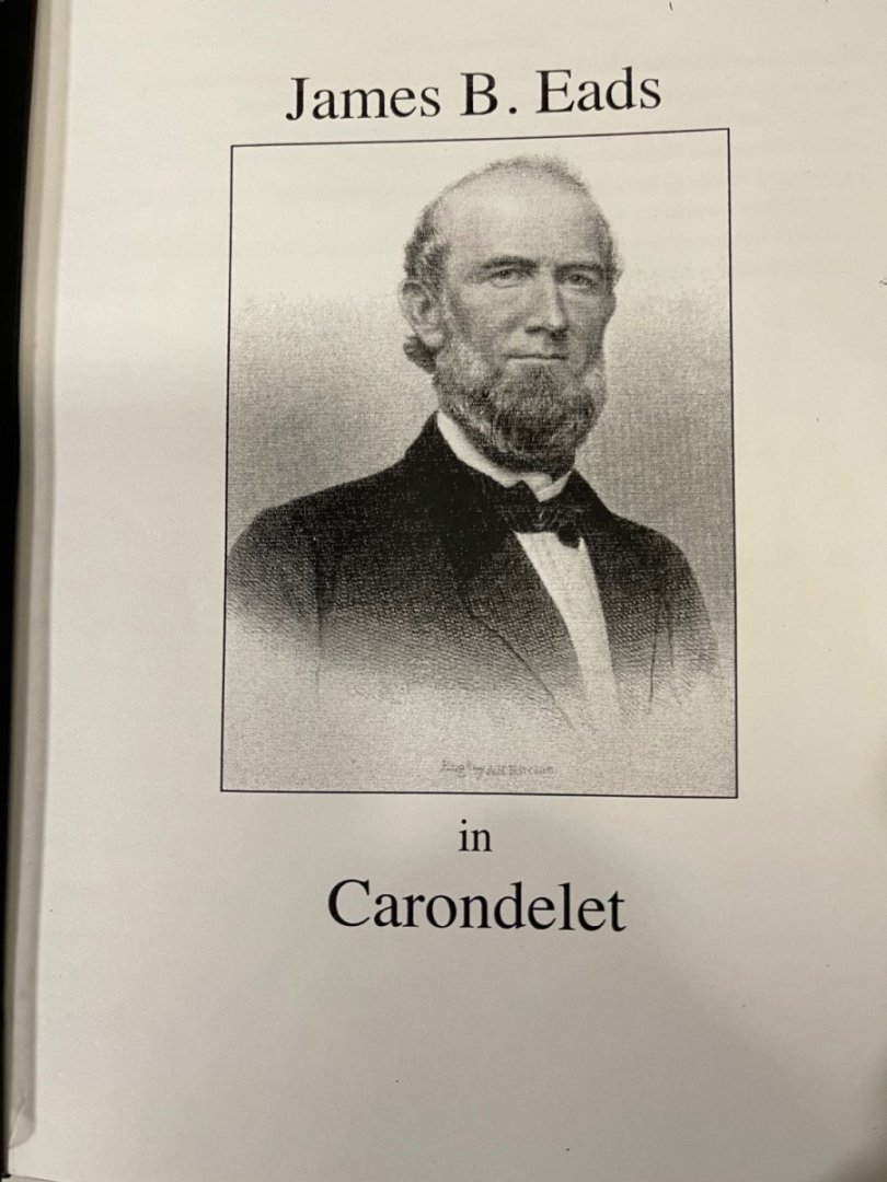
MTAYLOR, Thanks for your comments and questions. Regarding records/Archives for James B. Eads: There are indeed so many pages of archive web sites on the internet for Eads many endeavors that my searching for the related details regarding the related ironclad details has proved to be overwhelming. Our first attempted archive search in 2014 was a Model Shipcrafter Team visit to the Carondelet Library/ Museum set up for us by the Library Curator, Ron Bendett , in downtown St. Louis adjacent to the Shipyard where the ironclad "USS Carondelet" was constructed. This gave us a pretty good idea of the massive research effort we were facing. We were building our model of the USS St.Louis for the Missouri Civil War Museum which provided us with the National Park Service Historical Structural Report (HSR) which included Doug Ashley's 28 Sheet drawing of the ironclad, "USS Cairo" which was used as the primary source for its display in Vicksburg, Mississippi. When we contacted NPS Vicksburg for technical guidance we were advised that NPS Denver was manager of the USS Cairo display at Vicksburg. Our St. Louis Ship Modeling Team at that time consisted of many experienced 1800 era ship-modelers. however, only one of which had ever modeled the "USS Cairo". We immediately began to discover some blatant basic wooden ship construction & missing detail errors in the NPS USS Cairo plans which would be obvious on our large model scale of 1/2" = 1 ft {1:24]. We were advised by the NPS Denver that we should refer to several other National Park Service survey plans for the required corrections however Doug Ashley's plans were never corrected. Our secondary goal was then to document the errors we found. This included adding deck and Hurricane deckhouse roof cambers to our model. Hopefully more research will reveal or verify answers to other confusing construction features which include rudder control, internal access to the Hurricane Deck, and the location of the auxiliary steam engine. The Army was originally responsible for the Ironclad contract under General McMlellan via Brig. Get M. C. Meigs, Quarter-Master-General'and initially launched under Army command, but then transferred to Navy Command for active service upon which time some had to be renamed due to existing duplication already in the Navy . I agree that there must be Government Records and hope someone can retrieve them. JOHNHOWARD IMG_0377.mov
-
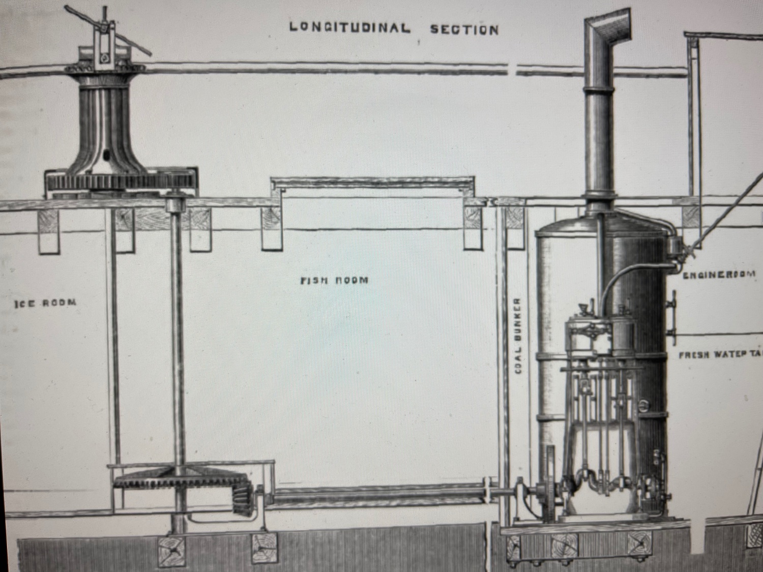
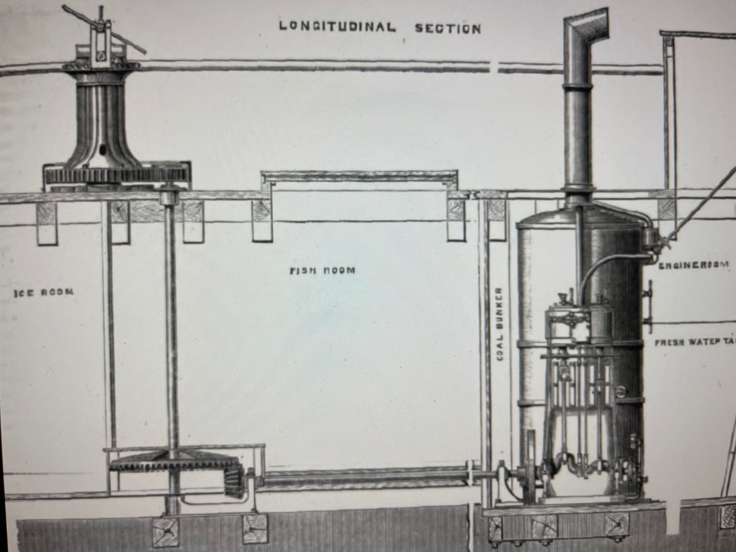
Part 6 of Steam Powered Capstan Study, One last issue to make this study complete is to determine how the high pressure steam was routed to the Auxiliary Steam Engine. which powers the capstan. Steam generated in the boilers is captured in the Boiler Steam Drum at the aft end of the boilers and then routed to the main Paddle Wheel Engines via insulated feed pipes amidship and then forward (on our model) of the USS St. Louis via the port side chine to the Auxiliary Engine control valve and piston drives for the PTO shaft which in turn powers the capstan via gears below the fore gun deck. We located the Auxiliary Steam engine on the Port side because this is where the only surviving City Class Ironclad the (USS Cairo) struck the Torpedo/ Mine and sunk, and possibly expelled the Auxiliary Steam Engine which was lost. Otherwise the Starboard equivalent location would be equally possible. Last year Brian Pierce, builder of his outstanding scratch model of the USS Cairo, and his NRG Forum Log, visited NPS Vicksburg and took many outstanding photos of the USS Cairo's damaged area in hopes of finding some remains of the Auxiliary Steam Engine. But, in vain, it appears any tell-tale metal fragments or other damage that may have survived were previously cleared away. We realize there was a lot of conjecture used to propose the location for various elements and perhaps we will never be able to positively claim our conclusions are correct. But since we started our research and scratch build model of the City Class Ironclad "USS St. Louis" in 2014, we haven't uncovered any "show-stoppers'" either, which is encouraging. We have just about exhausted all resources we can envision except for the records of the City Class Ironclad "USS Cincinnati" which was reportedly sunk twice and recovered, but finally destroyed by a river dragging operation. This is a"long shot" at best. but I wonder if any records survive of the 2 recovery operations. Any other suggestion would be gladly appreciated. Another possibility could be Archives of James B. Eads if any exist. Thanks to those following or participating in this Forum and good luck with your own projects. My personal goal is to increase participation in the "Research" portion of the Nautical Research Guild. JOHNHOWARD
-
Part 5 of Steam Powered Capstan for City Class Ironclads From the data provided in part 3 & 4 I believe that Pook's original plan was to utilize the Auxiliary Engine to both power the Steam Capstan and to provide low water protection for the boilers, however he left the details up to James Eads and stated in his spec that the Capstan location would be located later. The specified Auxiliary Engine was clearly an early 1800's high powered "over-kill" solution prior to use of the more efficient "Doctor". The City Class Ironclads were built in the amazingly short time of 6 months just in time for the start of the Civil War which was one main reason that Eads got the Ironclad contract. Eads was undoubtedly aware of up to date technology by owning factories and ship yards on the Mississippi. Somehow Pook and Eads agreed to the practical solution of adding the "Doctor Engine" for the boiler water level protection and modifying the powerful Auxiliary Engine by removing its water pumps without much contract paperwork documentation to power just the capstan. Perhaps Doug Ashley was made privy to Eads personal files helping him to surmise this configuration on sheet 28 of his NPS drawings of the USS Cairo. It is also possible that salvaged Auxiliary Engines were simply repurposed since it would be impossible to design & build a new engine in the time available. "Doctor" drawing and a photo my model of it for our USS St. Louis are attached. JOHNHOWARD
-
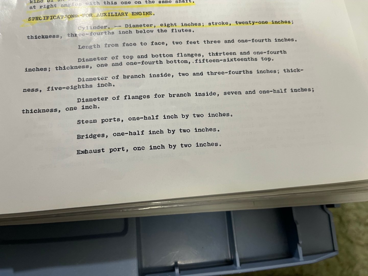
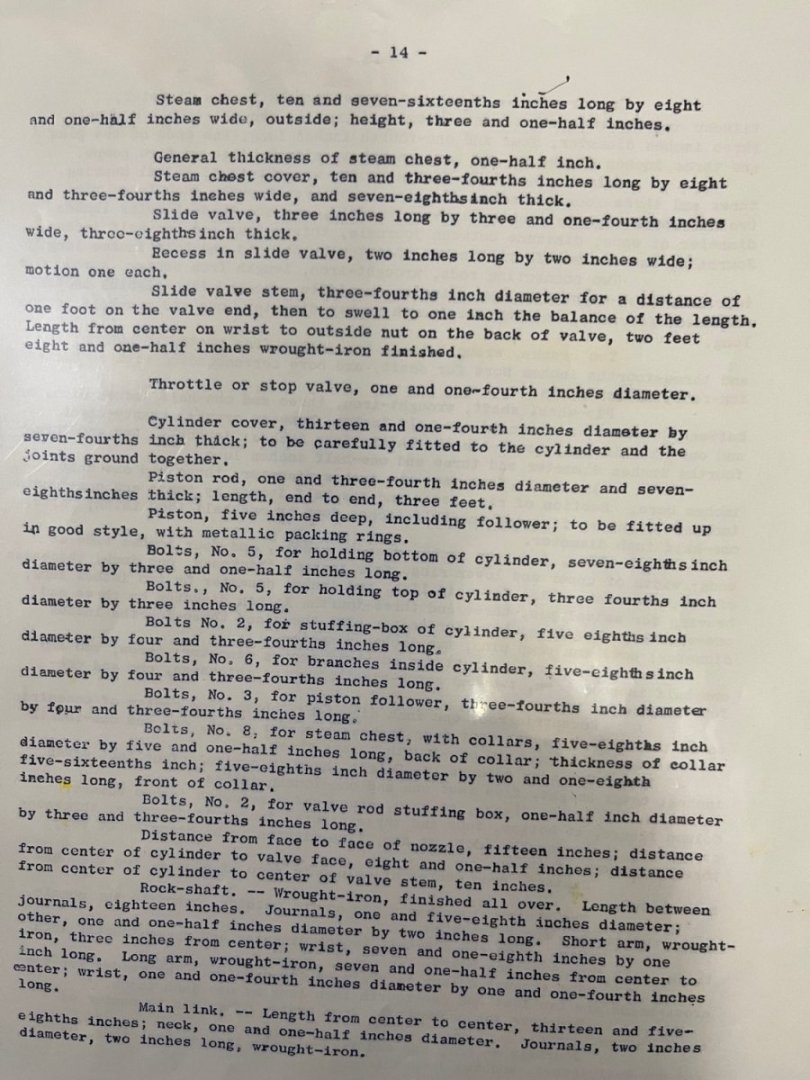
Part 4, Remaining Photos from yesterdays Part 3 text on Specs for the Auxiliary Engine as provided to James Eads. JOHNHOWARD

-
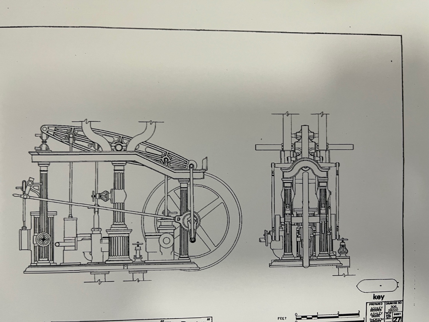
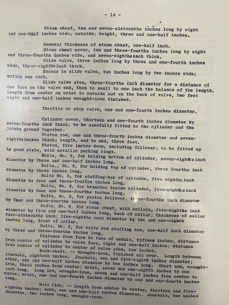
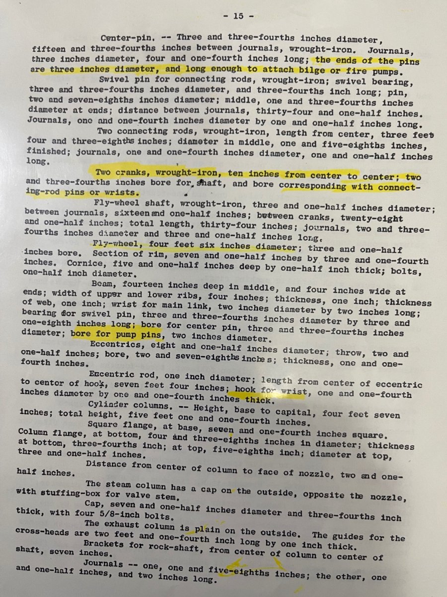
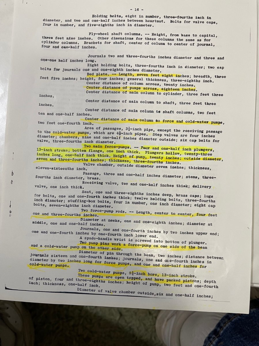
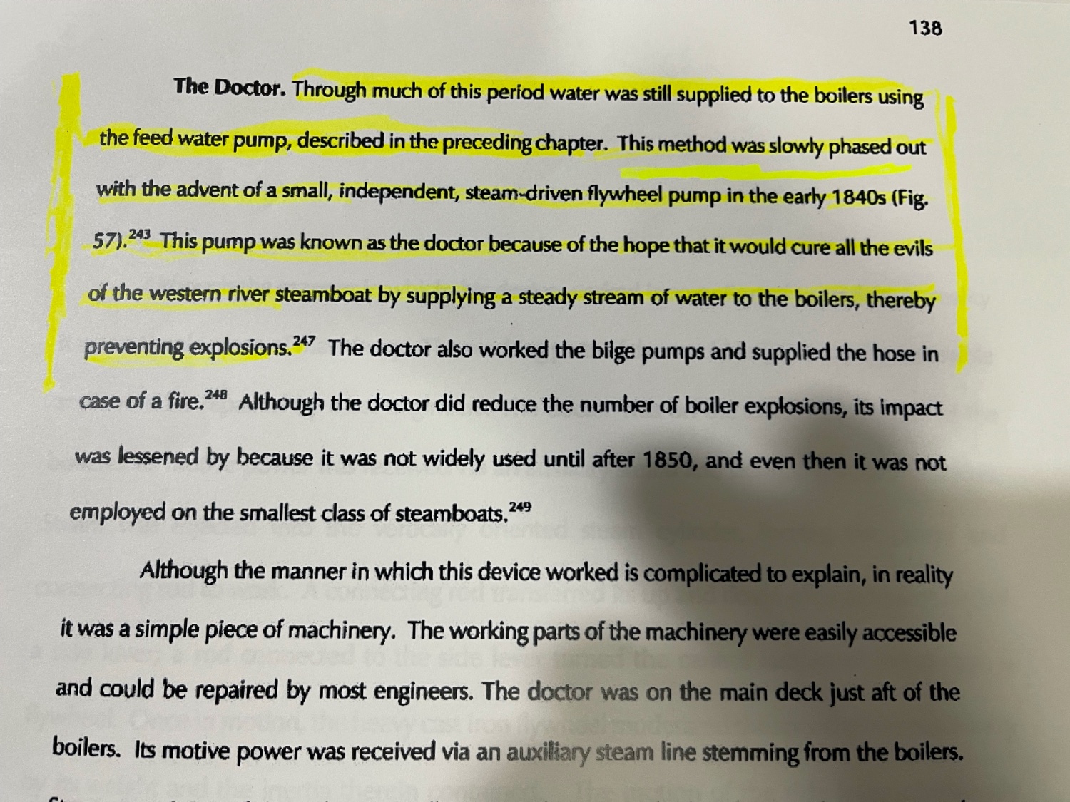
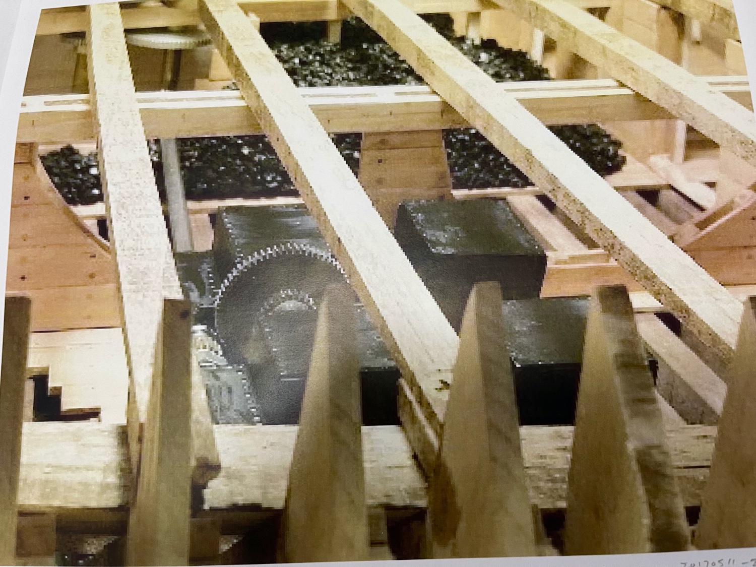
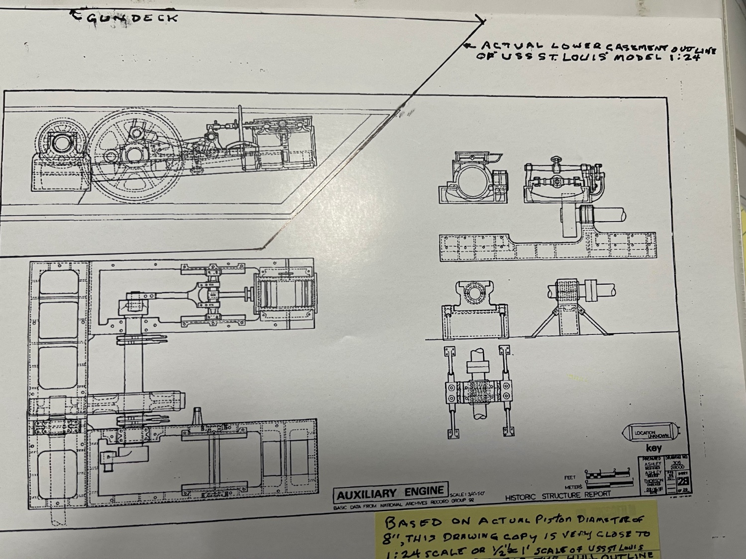
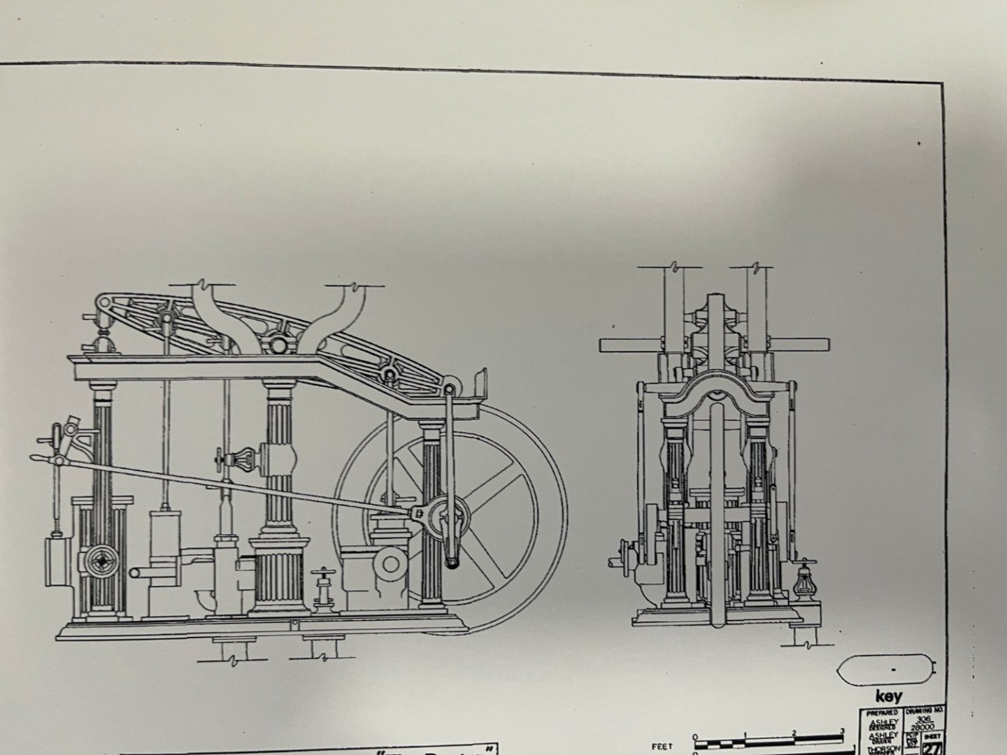
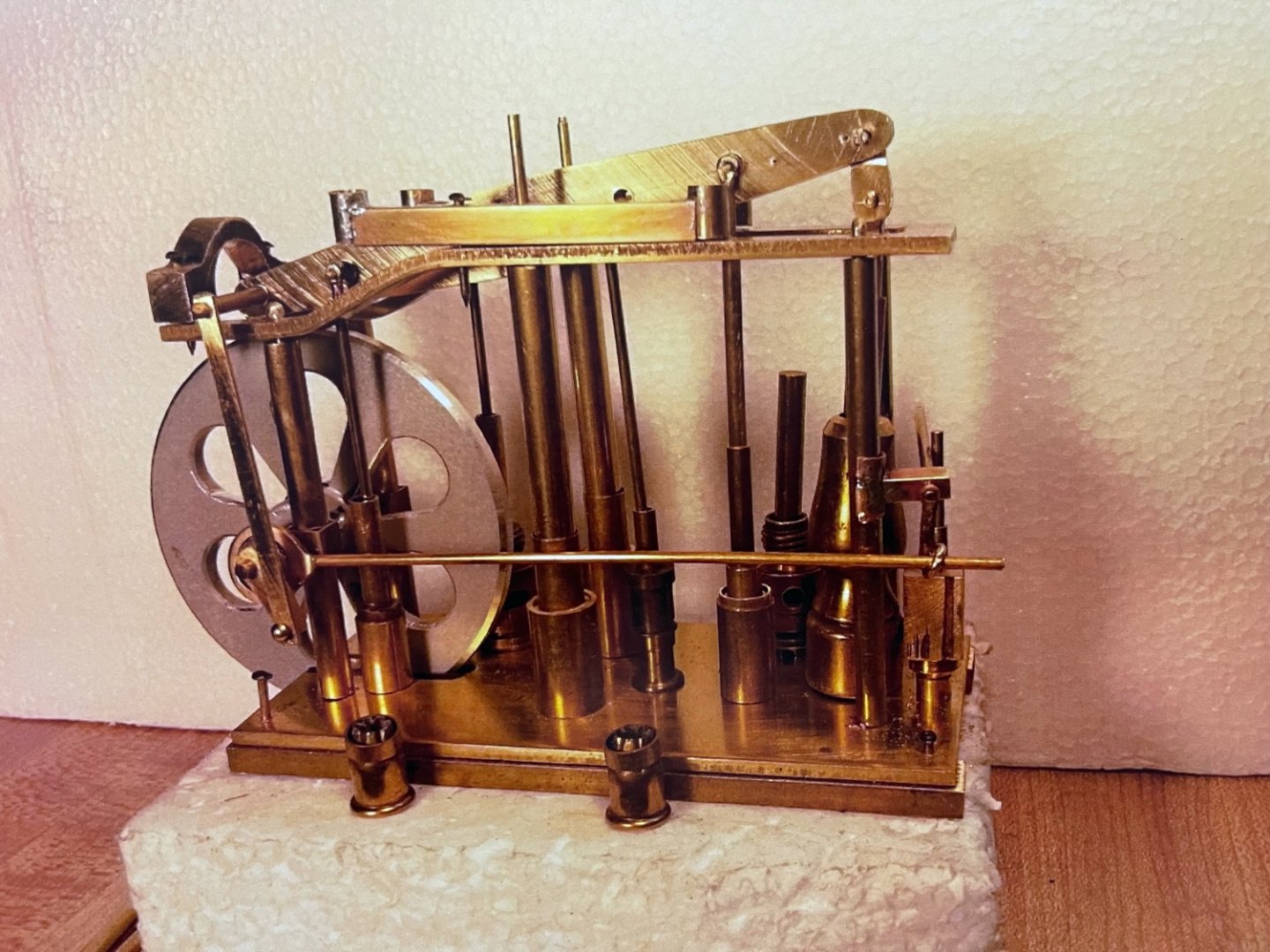
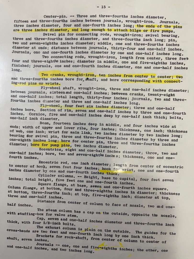
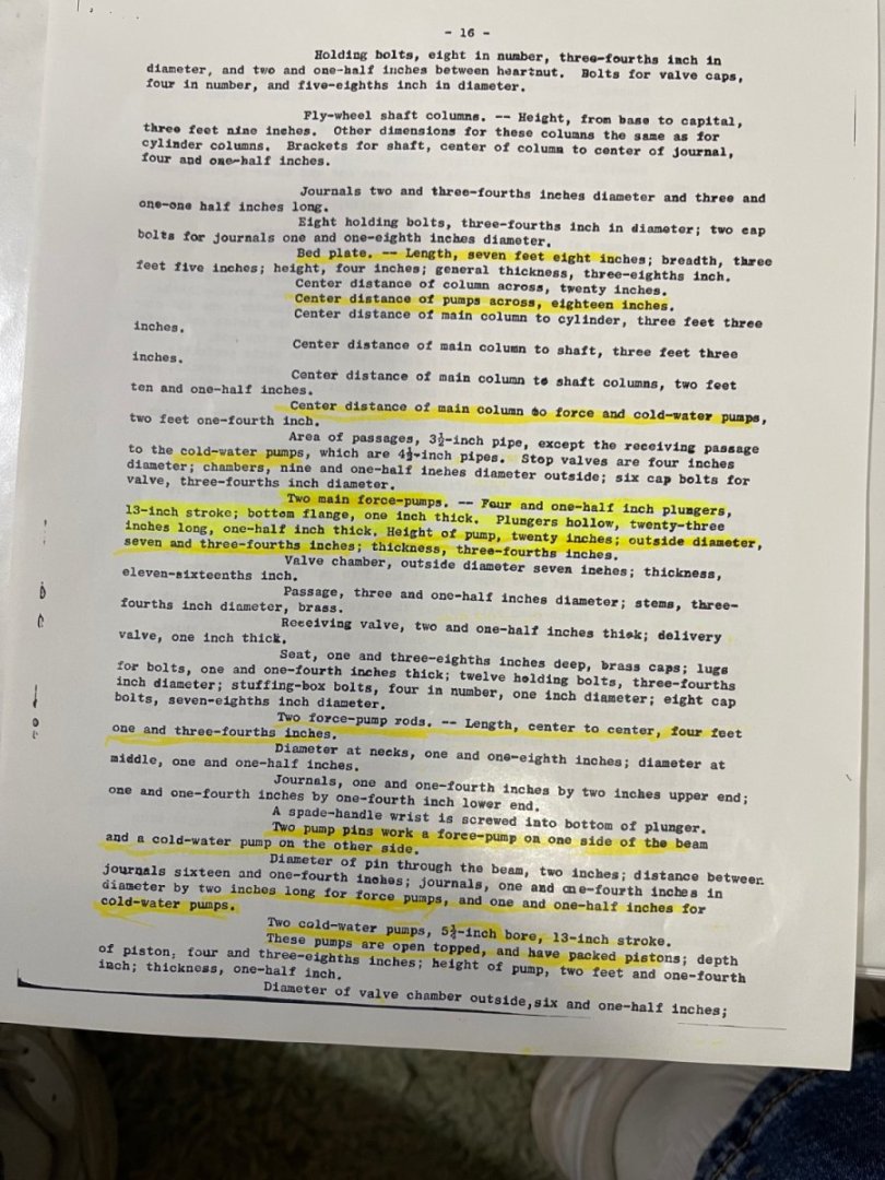
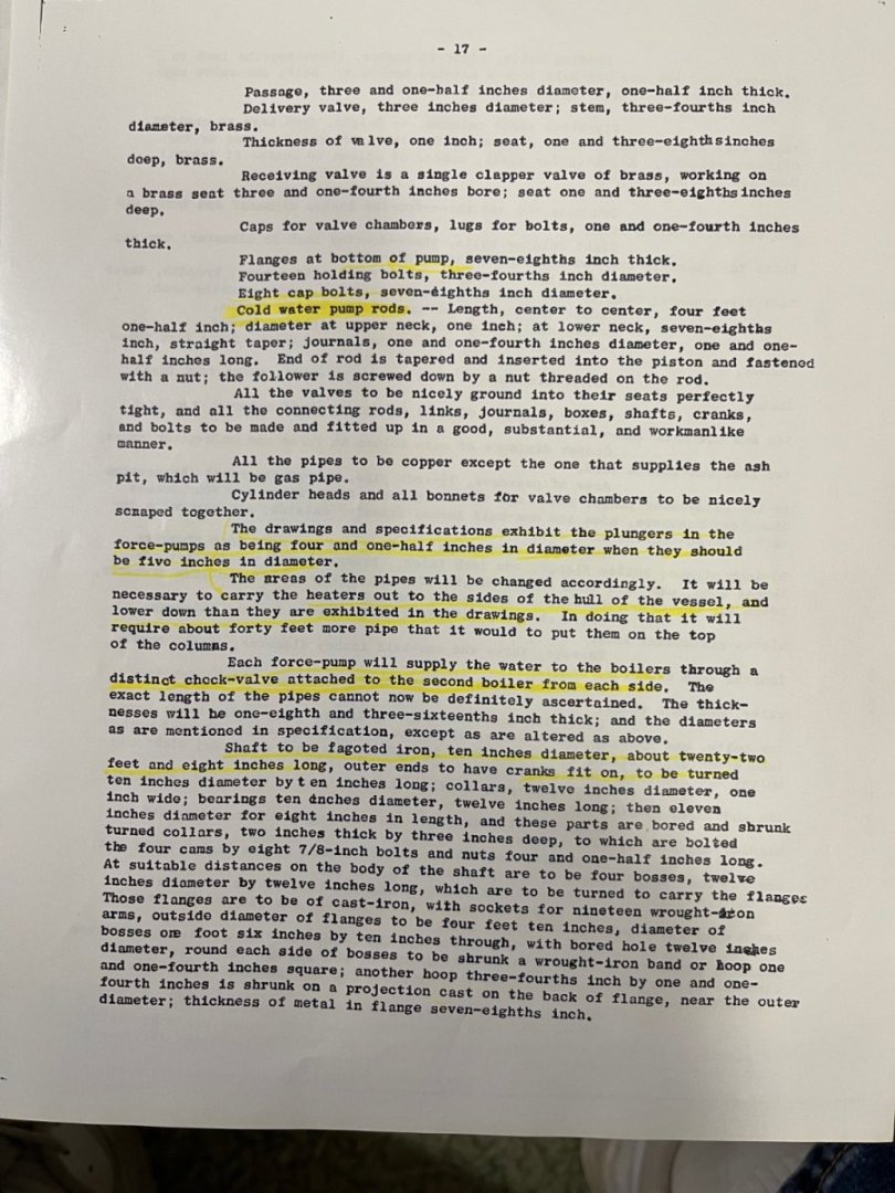
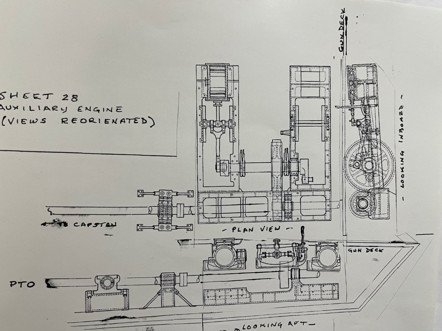
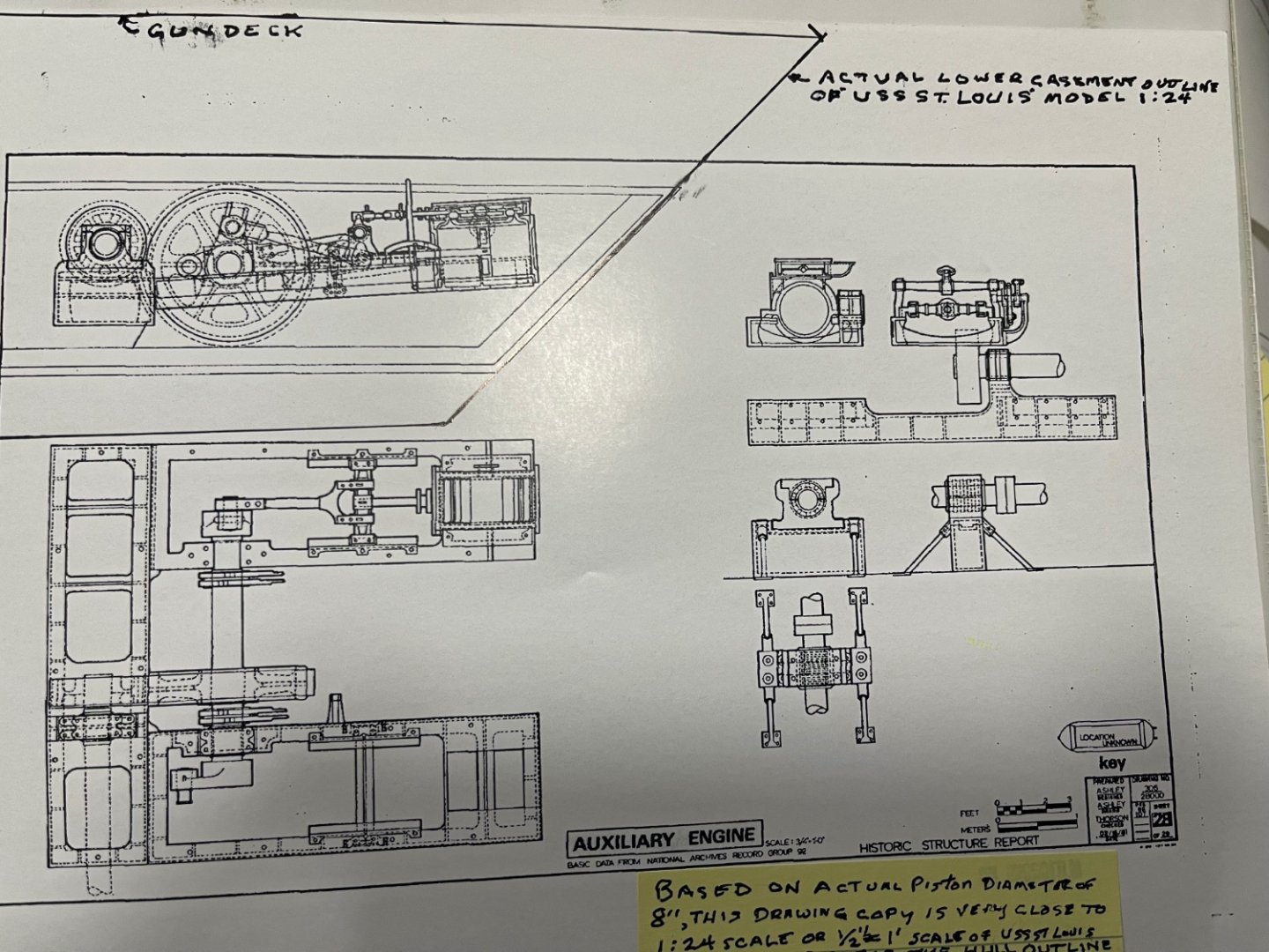
Part 3 of the evidence I used to locate the location for the Steam Powered Capstan: Figure 1 is a revised drawing of the Auxiliary Engine and PTO shaft with its views properly realigned to each other and Figure 2 is a close-up photo Following "of the resulting model of the Auxiliary Engine which we installed in our model of the City Class Ironclad "USS St. Louis" in 2017.. Following that are Pook's specifications for the Auxiliary Engine as provided to James B. Eads for construction of these ironclads with the most significant sections for this discussion highlighted in yellow. This specification reads more like an up close measurement of actual hardware than a design requirement spec and is a little difficult to follow precisely without detail drawings. Although Doug Ashley clams to have based his original Sheet 28 NPS drawing in 1984 on Data from the National Archives Record Group 92, he definitely appears to have superimposed the Engine on a City Class Ironclad hull. He also referenced Archives Record Group 92 as his source for other ironclad hardware such as the boilers and firebox which are not very accurate. I'm not exactly sure how data gets put into the Archives Record 92, but he is correct regarding this Auxiliary Engine, however the Record 92 also currently includes my personal photograph of my model Capstan and PTO Shaft Gearbox that I took in 2017 for the USS St.Louis and downloaded to Gerhadt's "Live Steam USS Cairo Scratch Build NRG Forum". One interesting fact concerning the Auxiliary Steam Engine in the Archives and NPS drawing is that it appears not to contain the feed water pumps or "Force" pumps described in Pook's Auxiliary Engine Specification as provided to Eads. As can be seen on the last attachment, "these pumps were "slowly phased out with advent of a small, independent, steam-driven flywheel pump in the early 1840's known as the "Doctor". (Photos of my model of the "Doctor"for the USS St.Louis are included earlier in this forum. It was positively seen during the USS Cairo recovery in 1964, but was also lost when the hull split in half.) The Doctor was much more practical for a feed pump and was located on the Ironclads centerline immediately aft of the Boilers rather under the fore gun deck in a coal bunker! . PHOTOS TO BE CONTINUED IN PART 4 JOHNHOWARD
-
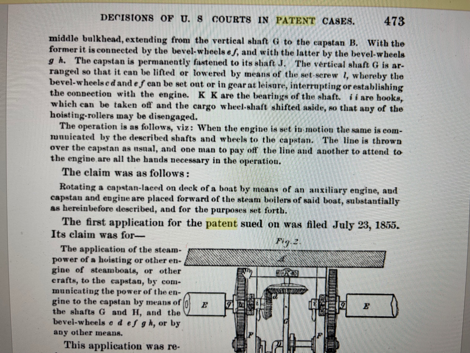
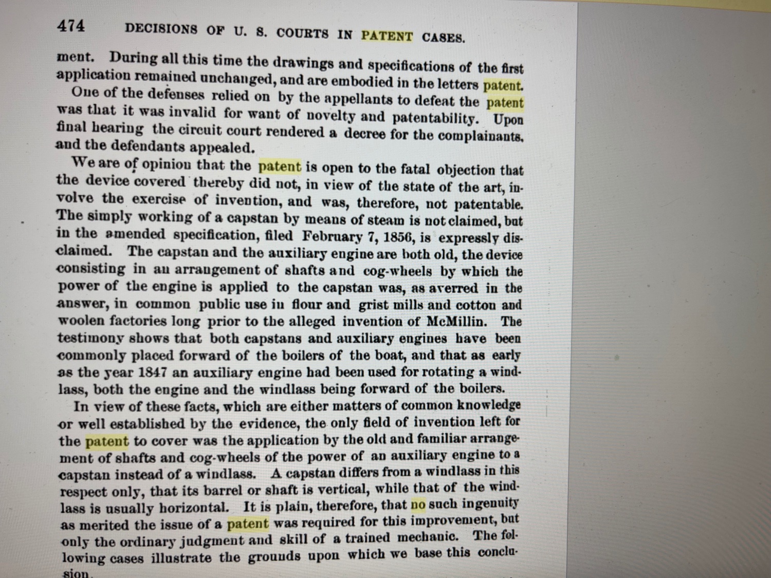
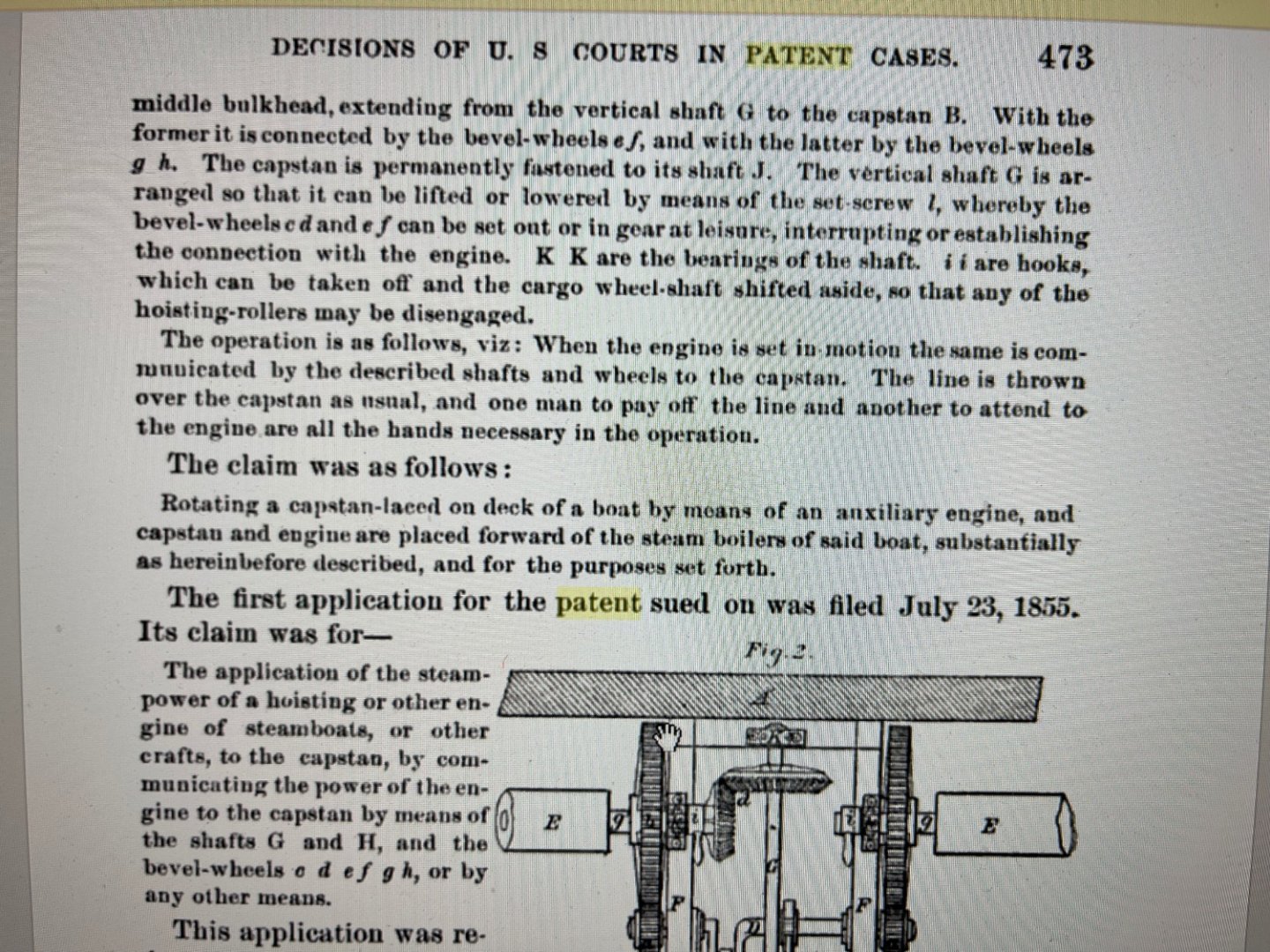
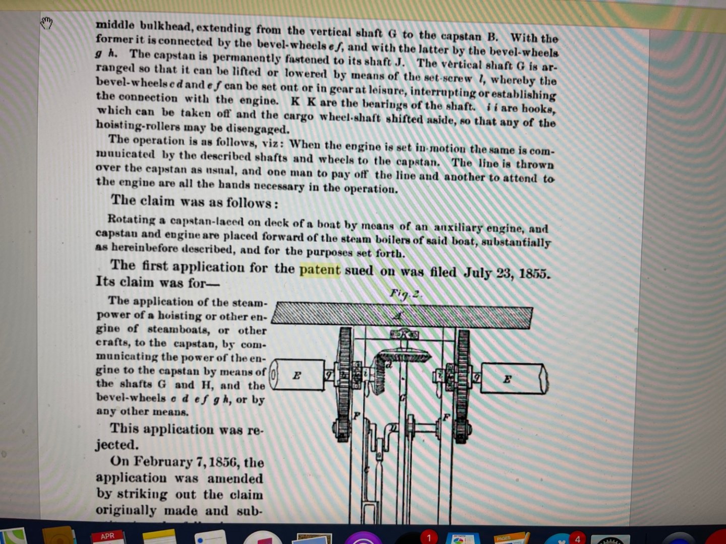
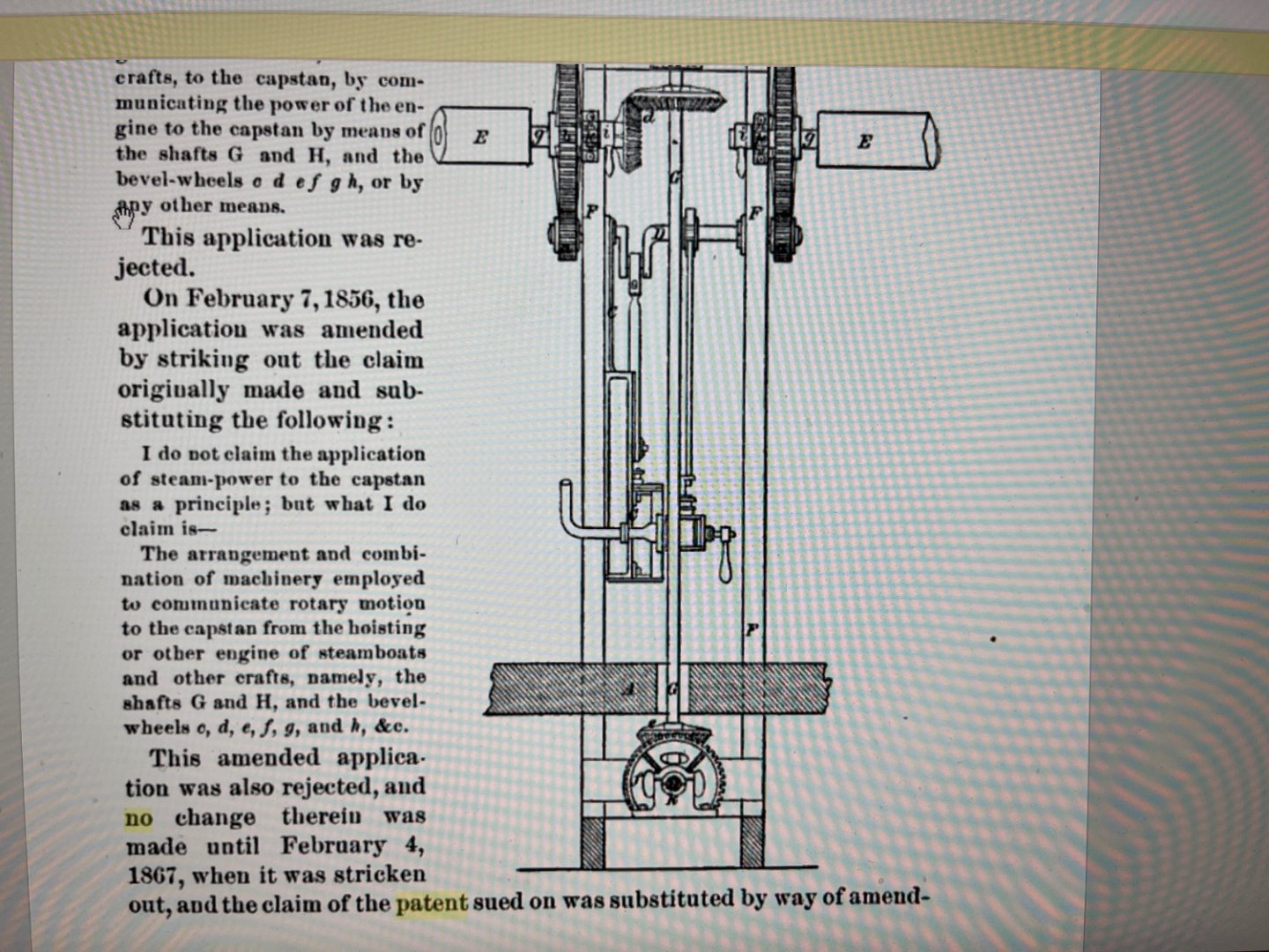
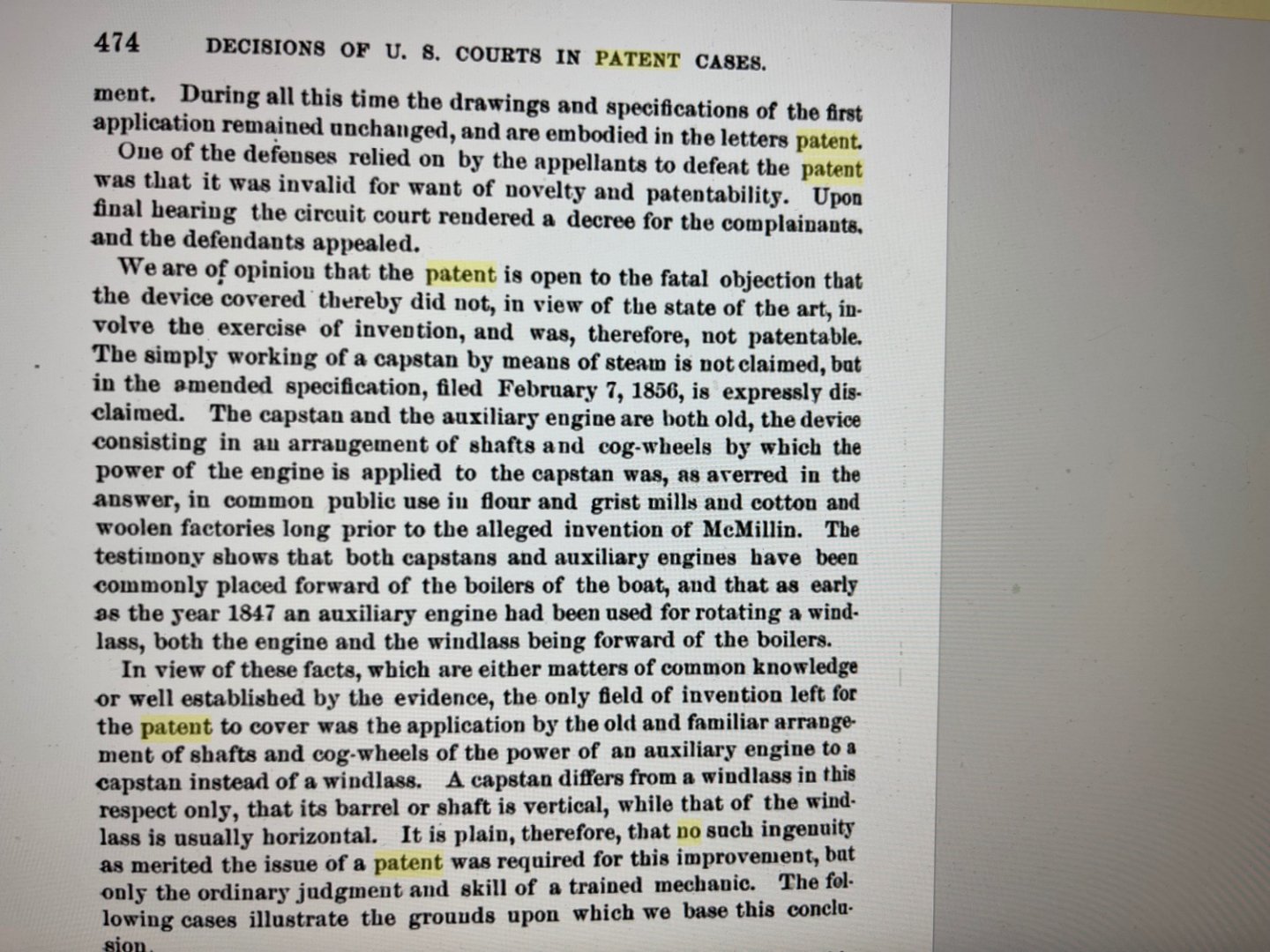
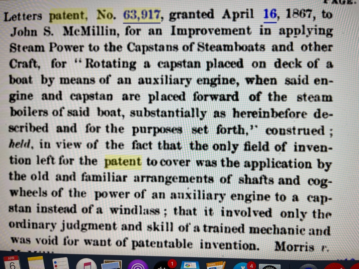
Roger, Thanks for your assessment of the steam powered windlass and capstan usage. The steam engine was being perfected in the early 1800's and soon thereafter it was being proposed to replace manpower for everything in sight, which directly bolstered the Industrial Revolution in Europe and America. My search of the Steam Powered Capstan Patent History led to some interesting information as related to Patents for its use on the Mississippi Steamboats and Ironclads leading up to the US Civil War era. Attached are 5 excerpts from the "Decisions of the U. S. Courts in Patent Cases" that I used to establish a date for its introduction in the U.S. The applicable sections are highlighted in "Yellow". The earliest patents, startingbin 1855 were all rejected until "Letters" Patent No. 63,917 was granted to John S. McMillan on April 16, 1867 which appeared to be too late to support its use in time for Ead's Ironclads. However I discovered that a "Letter Patent" was really an "honorary award" commonly bestowed on someone for unrelated personal services or favors provided to a European Monarch such as a King and not for any real technical achievement. John S. McMillan was a Mississippi Steamboat Captain at this time but I never determined who the United States Monarch was!?! Regardless of this, the US Supreme Court in 1884 eventually "Voided" this "Letters Patent" which meant that it never really existed! It also ruled that "a Steam Powered Capstan was not Patentable as it was just a Steam Powered Windlass rotated upright and such devices were in general use since the 1830's! No patent infringement claims were ever approved or paid. By far, the most common Steam Powered Capstans that I discovered during the Civil War erawere actually PTO shaft driven. High Pressure Steam was routed from the same main ironclad boilers which also powered the paddlewheel. This arrangement was also universally used in factories which ran on centralized steam power plants. Later on, by the 1880's several patents were actually issued for Capstans with integral steam piston drives instead of PTO shaft drives. James B. Eads, who was the Chief Engineer responsible for the construction of the City Class Ironclads was also the owner of the shipyards and several industrial factories in the St. Louis area which undoubtedly relied on steam powered machinery such as the PTO Shaft drive in picture 6. The Eads Bridge in St. Louis was named in his honor. JOHNHOWARD
-
Roger,(and FORUM Followers) Thanks for your comment regarding chain or rope cables for the City Class Ironclads. The capstan recovered with the USS Cairo appears to be designed for rope cables and not chains but I think the real reason for Pooks' specifying a Steam Powered Capstan was more likely for recovering the 500 ton Ironclad from grounding on a sandbar or in a river bayou than simply for raising the relatively small anchors. On many occasions the Ironclads were simply moored to trees along the river banks without using the anchors at all.The Mississippi River was notorious for such groundings of Passenger Steamboats during the Mid-1800's and various complicated techniques were used to re-float them. Thunderstorms and flash-flooding in the lower Mississippi River area were a serious threat to water levels that couldn't be ignored by a Naval Military vessel during the Civil War due to the possibility of being stranded and easily captured by the Confederate forces. In fact you could consider a "Steam Powered Capstan" to be a "Secret Weapon" for the Union Navy. By the way when, in 2017 that I first suggested this location for Ashley's Sheet 28 Auxiliary Engine/Steam Powered Capstan on Bernhard's "Live Steam USS Cairo NRG Forum", you asked whether or not "Steam Powered Capstans" were in use on the Mississippi at that time. My answer "Yes" to your question appeared to be a simple search for a US Patent date, which turned out to be anything but simple as I will soon explain. Attached is a clearer drawing of my proposed location for the Auxiliary Engine and PTO Shaft driven Capstan that we included in our model of the USS St. Louis. This was determined by my "Reverse Engineering" of the issues provided to James Eads, when he built the ironclads. I found no indications of a windlass on the USS Cairo, but the US Supreme Court determined that "a capstan was just a winless turned upright!" JOHNHOWARD
-
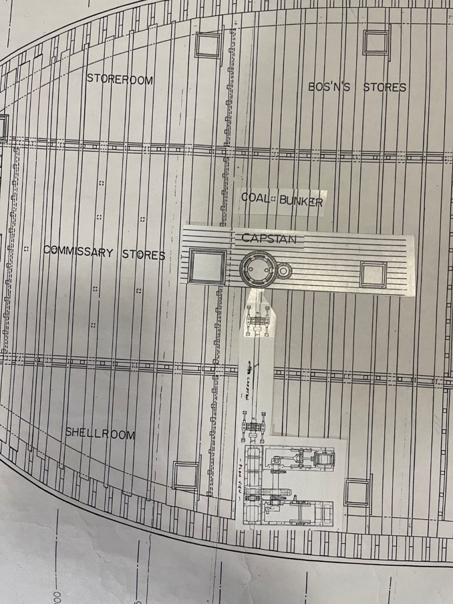
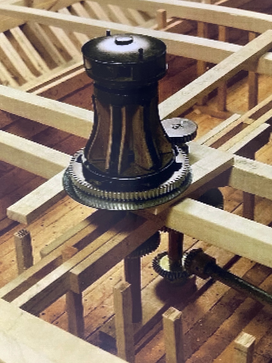
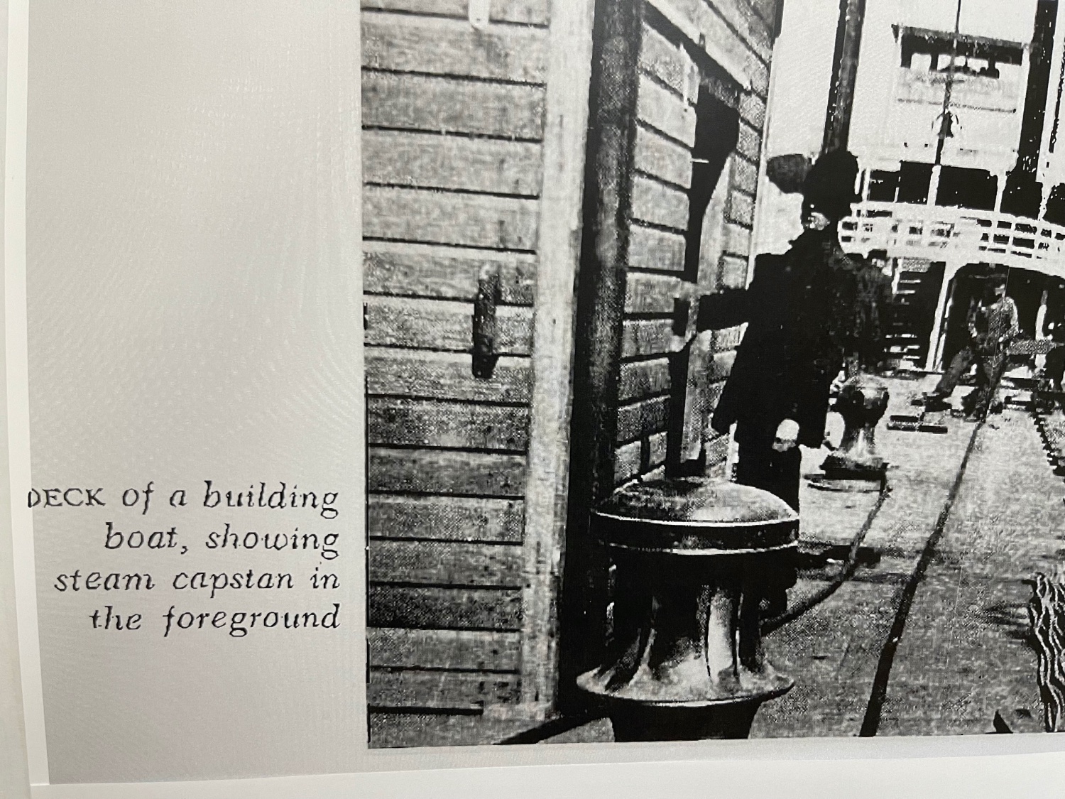
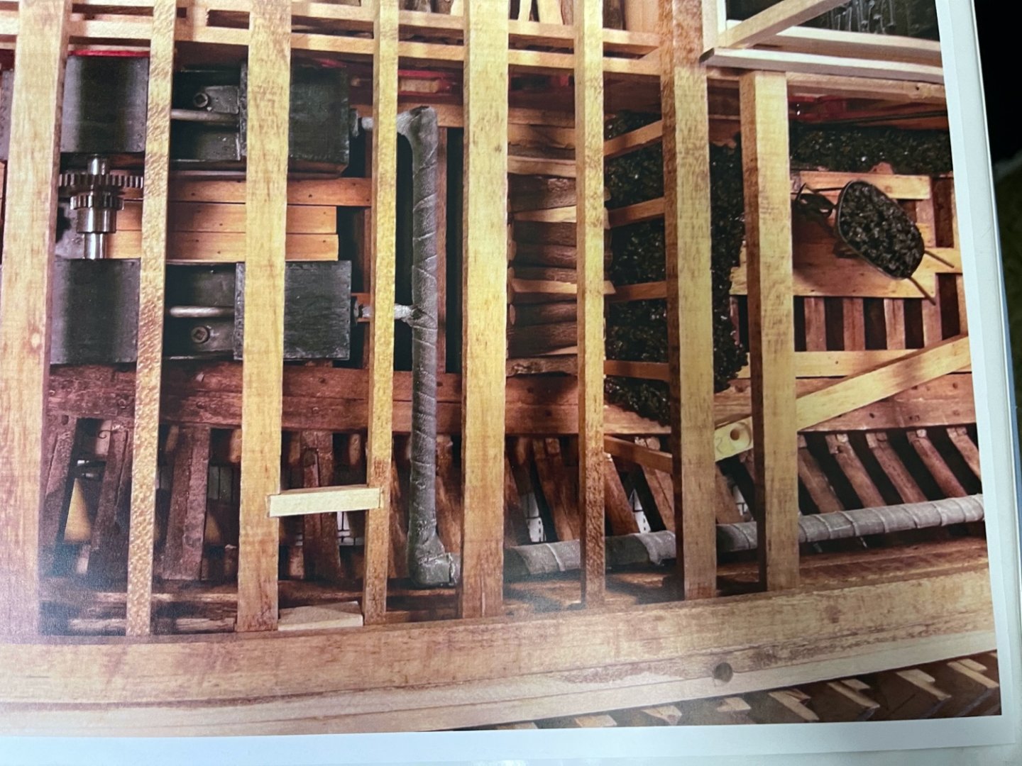
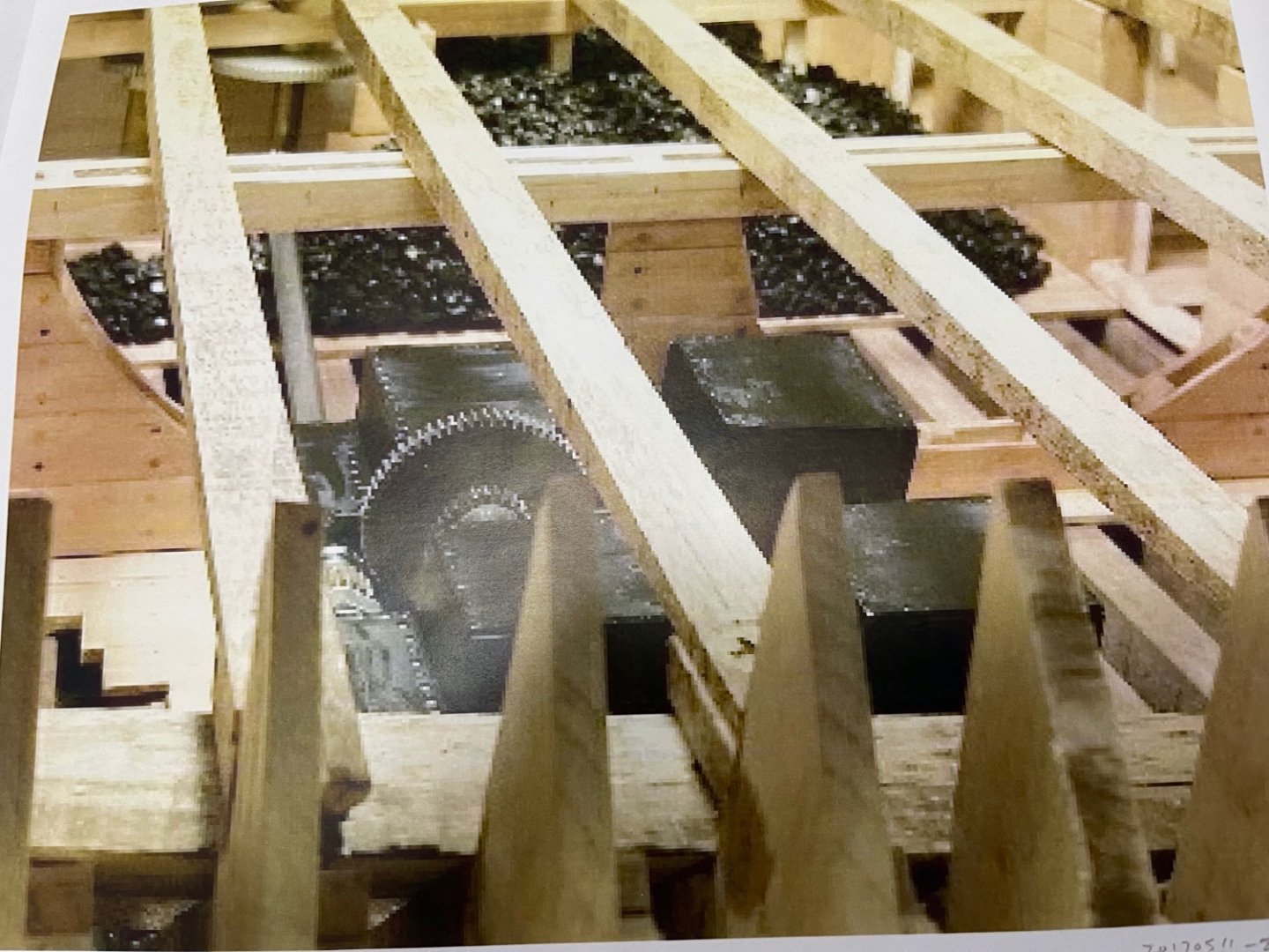
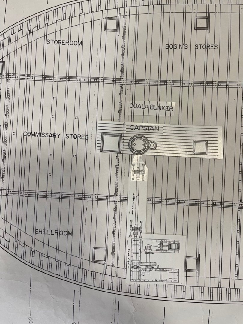
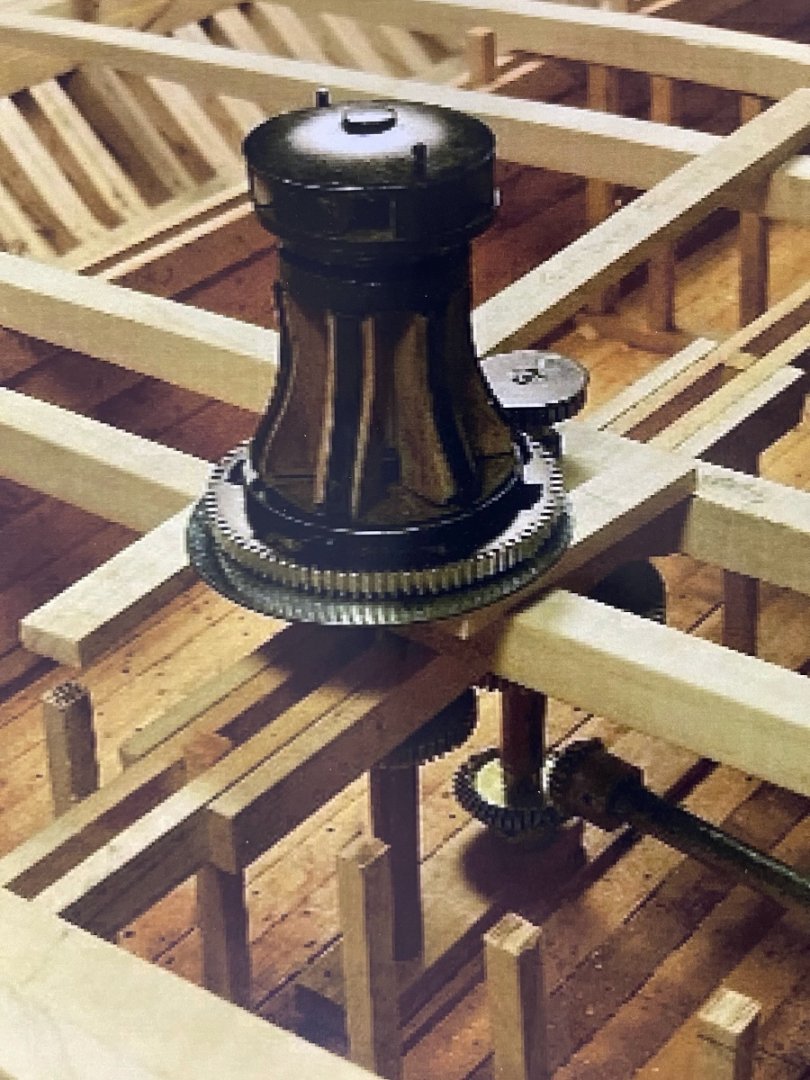
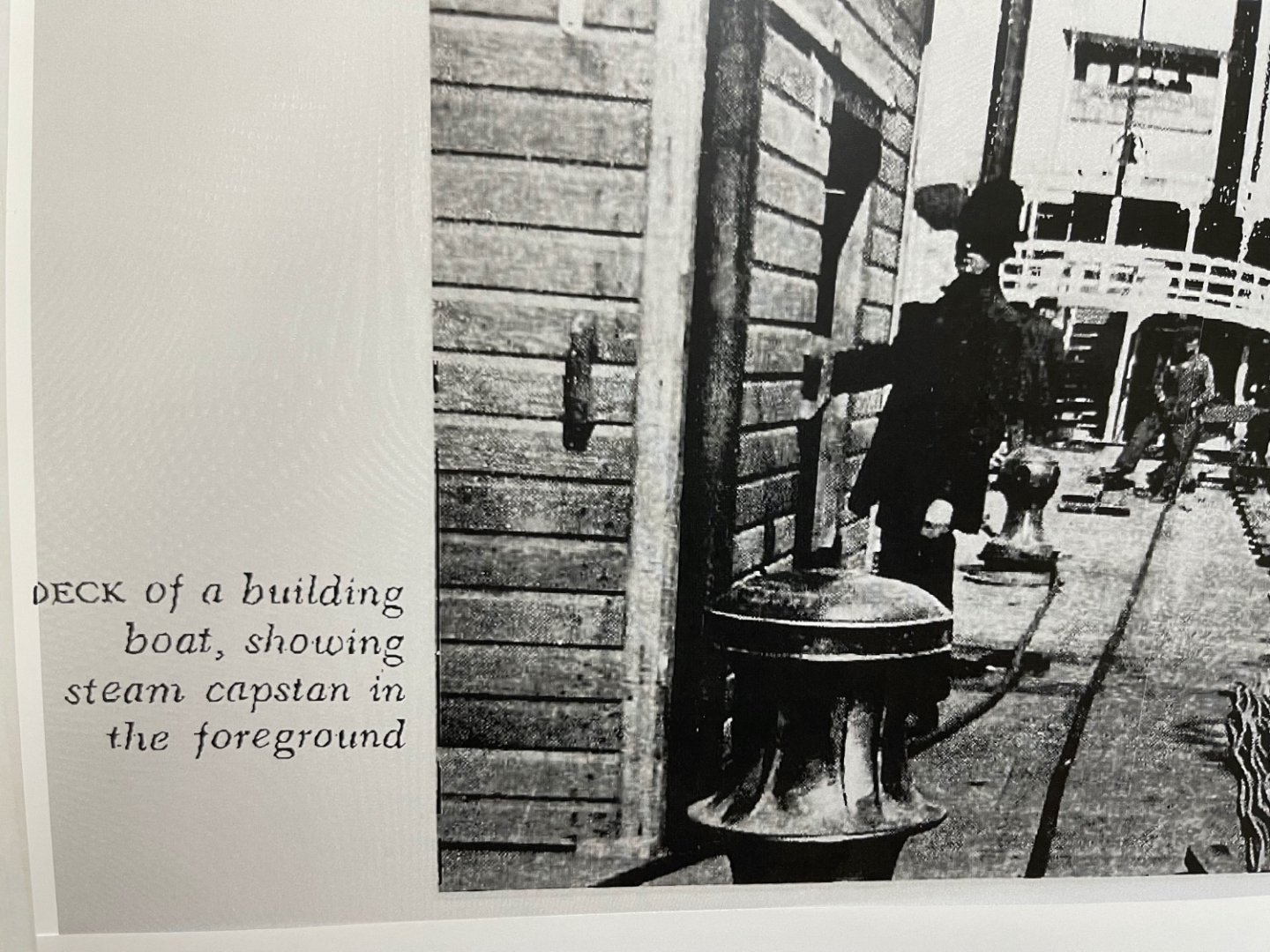
Part 2, Location of Auxiliary Engine/ Steam Engine Powered Capstan on City Class Ironclads Attached is a photo of our mock-up made in 2017 for our model of the USS St. Louis of my proposed location for the configuration used by James B. Eads to provide the "Steam Powered Capstan" for the "City Class Ironclads" in accordance with Samuel E. Pook's original specification. In the near center of this photo is the "U" shaped top view of the "Auxiliary Steam Engine" which is described in great detail in Pook's specification for the Auxiliary Engine and also on Doug Ashley's Sheet 28 drawing of the Auxiliary Engine. The PTO Shaft can be seen protruding from the Auxiliary Engine to the gears below the Capstan centerline itself which was recovered "intact" and is on display at Vicksburg.. This mock-up was later firmed up on our USS St. Louis model and most of the gun deac was planked in this area severely restricting observation. The actual Capstan itself contains the capability to disconnect it from the PTO shaft gears for manual operation via 8 bars in the Capstan head (one of which is shown protruding from the rear). The Auxiliary Steam Engine itself was controlled by a removable lever protruding thru a slot in the gun deck that operated a steam valve on the Auxiliary Engine. The third photo depicts a similar Civil War contemporary lever controlled capstan on a river boat.This arrangement would be required because the forward section of the gun deck must be cleared to safely operate the forward battery of cannons. The stub of the steam valve on the Auxiliary Engine to interface with this handle can be seen on Ashleys' Sheet 28 drawing. We have so far tried unsuccessfully to physically verify the proposed location for this configuration on the USS Cairo remains at Vicksburg National Park and contact with original salvage participants, however I have found no evidence which contradicts this hypothesis. [Next I will address some of the issues previously raised and solicit any additional ideas you may have.] JOHNHOWARD

-
Modelers of City Class Ironclads USS Cairo and USS St. Louis following this Forum, For the past 6 months I have been trying to conclusively resolve a final mystery as to the location of the "Auxiliary Engine" depicted on Doug Ashley's 1981 National Park Service Drawing, Sheet 28 (Photo 1) below for the USS Cairo which he identified as "Location Unknown". He referenced "National Archives RecordGroup 92" as his source for this drawing. When I contacted Elizabeth Joiner, who was the Vicksburg USS Cairo Museum Curator in 2014, she said " They had actually seen this item during the USS Cairo recovery, but unfortunately lost it in the river. Unfortunately although I have not been able to conclusively prove my research is correct, all circumstantial evidence leads to one conclusion so I will present it here for your critical review. PART (1) Also missing from Ashleys Historical Structural Report (HSR) is any indication of the Steam Powered Capstan as specified in Pook's original specification for his City Class Ironclads. Several years ago as we were building our large 1:24 scale version of the USS St. Louis and simultaneously coordinating with Gerhard on his NRG Forum for his "Live Steam" version of the USS Cairo I proposed that the Auxiliary Steam Engine was actually used to power the capstan which is located in the middle if the forward gun deck above the main coal store room. The Auxiliary Steam Engine is obviously a twin 6-inch diameter piston engine driving something via a PTO shaft located in the chine of the hull. Since we were planking the gunlock at that time we had to immediately include the Auxiliary Steam Engine and PTO shaft in our model before losing access to the lower hull. (To be continued) JOHNHOWARD
-
Brian & Pat, You raised some darn good issues and it took me awhile to remember back about 10 years when we started planning for our USS St. Louis model of the City Class Ironclad for the St. Louis Civil War Museum(SLCWM) for answers. First about the drawing in my last (#515) posting. This was a cover sheet provided by the SLCWM for Ashley's "HSR" 28 Sheet Set of drawings at scale of 1: 48 for the model they wanted us to build for them at twice that scale or 1:24. This sheet has no title block but is marked in the field as "USS Cairo" , Scale 3/8 ' = 1' 0", ATTERIDGE-83. At that time none of our Model Shipcrafters knew anything about the USS Cairo or other City-Class Ironclads. Ashley's drawing is dated 1981 and contains all the required information, so we simply copied his 28 sheets at twice scale. While building the USS St. Louis at the large 1: 24 scale we discovered numerous physical inconsistencies between Ashley's drawings alignment of the individual decks. One of these was the location of the aft Ventilation Funnels shown in your previous Gun Deck/ Hurricane Deck Overlay drawing. Our initial interpretation determined that your light blue parallel lines actually depict the cross-over walkway mis-located too far forward by about one width space. Your red line is not a full wall but is actually a short open hand railing on the aft side of this crossover walkway, with an opening in it for a short stairway down to the floor of the engine room. The light blue circle obviously represents the ventilation funnel but we believe it is actually also aft of the boiler room wall further aft over the open cross-over walkway. Since the walkway is also probably has a fine open grated surface it wouldn't disrupt its ventilation affect.. I also agree that your sketch, Brian, of a combined ventilator, skylight has a lot of merit. There is also mention in the Log of a metal forge area below deck of the USS Carondelet, near the Hog Chain Stanchions, outboard of the Boiler room that would need some ventilation. Still having fun, JOHNHOWARD
-
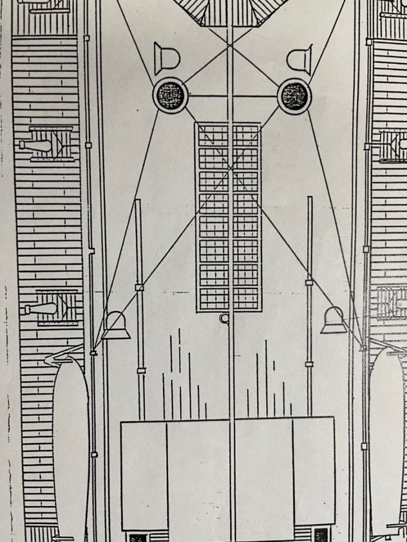
Hi Brian, It's too bad "Old Abe" didn't use one of his hot-air observation balloons to take a photo of an ironclad for us future model makers sanity sake. I'm still having a problem with your suggested locations for the aft ventilation funnels relative to the "Hog Chain" Posts. I''ve attached the plan view & side view of Ashley's HSR version which I think is relatively correct. The problem of using the single USS Pittsburg photograph appears to be following the unknown Ironclad deck edge , 45-degree casement & vertical Hammock Rails, all relative to the photographer position, you tend to lose the horizontal location on the deck. If you visually connect the 4 Hog Chain Posts with imaginary lines in the USS St Louis Skylight Hatchway photograph, the positions of both the port and starboard Ventilation Funnels appears to be just forward the Aft Hog Chine Posts and at the aft gunport station. The hatchway you found appears to be in the same vicinity and for that reason, I would seriously consider a multiple function hatchway/ventilator. Some of the photographs show the ventilation funnels in various stages of height disassembly for either optimum ventilation or temporary storage on the decks, thus confusing our possible interpretations. One final consideration for the. aft ventilation funnels is that they must be located where they best ventilate the extremely hot engine rooms; not the gun decks, and not the boilers which already have large open grates or gun ports for this function. While there is a possibility of modifications between the City Class configurations, they were all built within a year of each other and neither the USS St. Louis nor the USS Cairo served very long before they were sunk. The USS Cincinnati was sunk and re-floated at least twice and further research into its repair/overhaul record would be of great interest. JOHNHOWARD
-
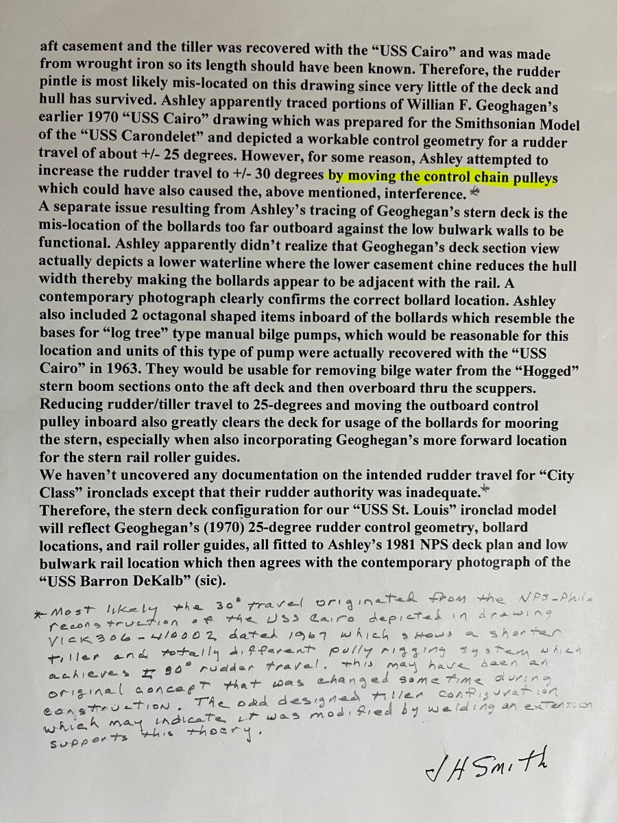
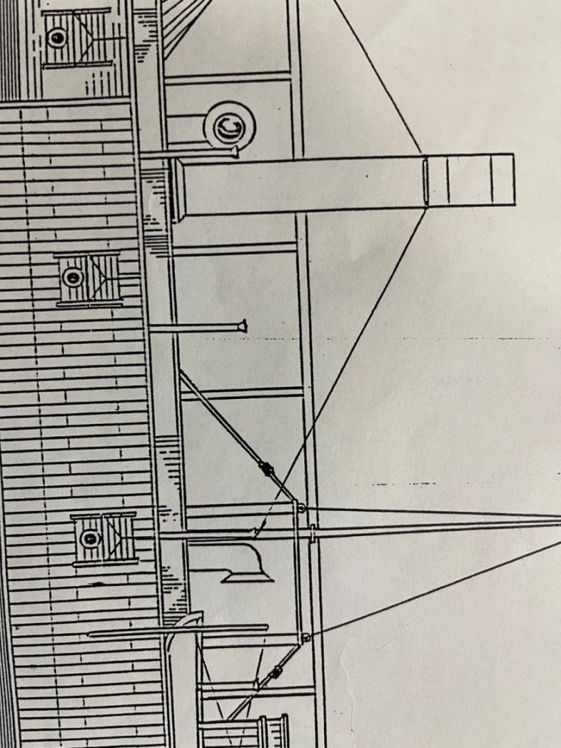
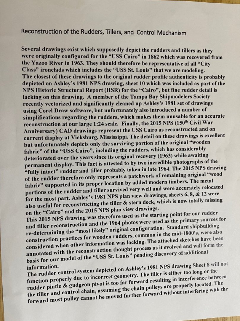
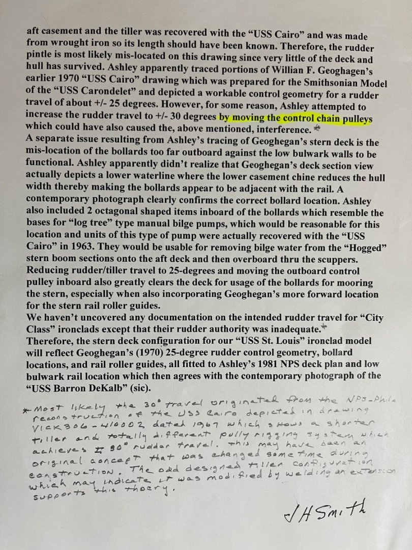
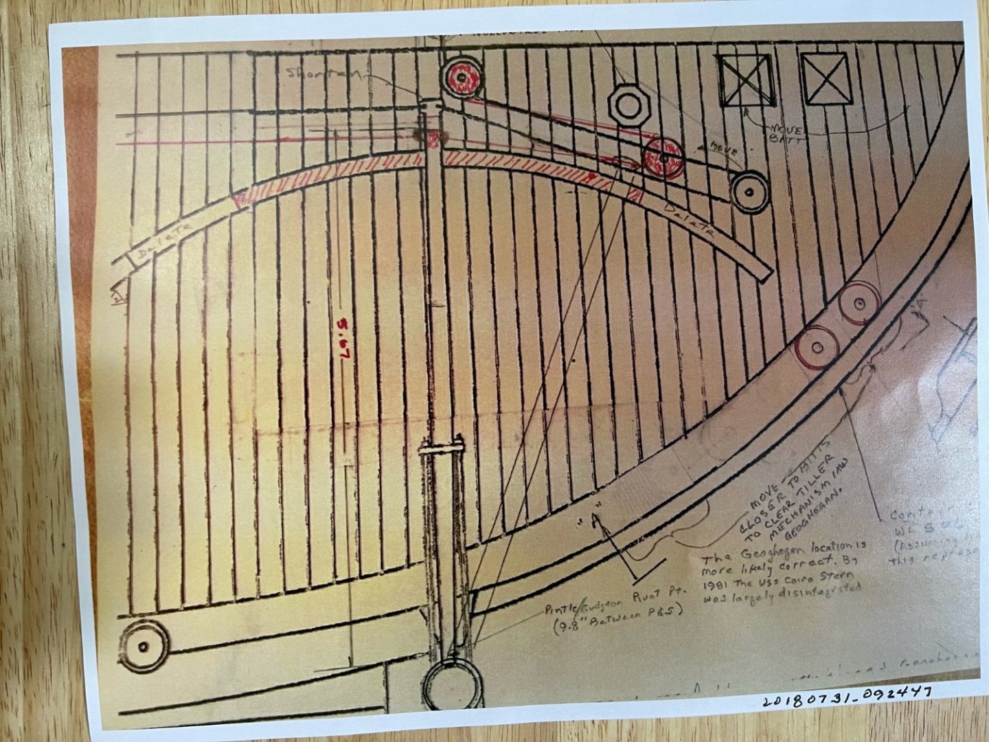
In response to several inquiries I have recently received regarding USS St Louis & other City Class Ironclad Rudder Controls resulting from Tim's photo Posting #257, the attached document represents my original research in 2018 and the plan we are following for the USS St. Louis Ironclad Model. The dual rudder control authority for the City Class Ironclads was notoriously poor and apparently was modified during initial trials or later service life. The tiller appears to have been lengthened and geometry revised. The biggest problem may have been slack in the lengthy cable, chain or hawser ropes between the steering wheel and the rudder tillers. I'm not certain that steel cable was available so chain was the best alternative for reducing this slackness and apparently not really a great solution either. The actual USS Cairorudder, tiller and aft deck was recovered pretty much intact, being made mostly of metal so the early NPS surveys should be fairly accurate. JOHNHOWARD

-
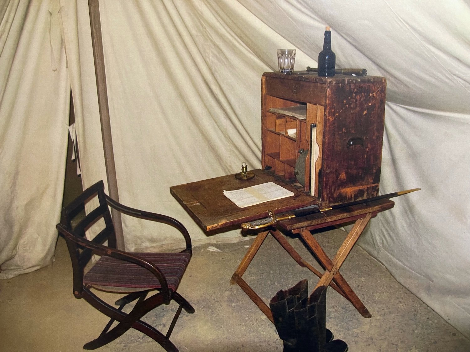
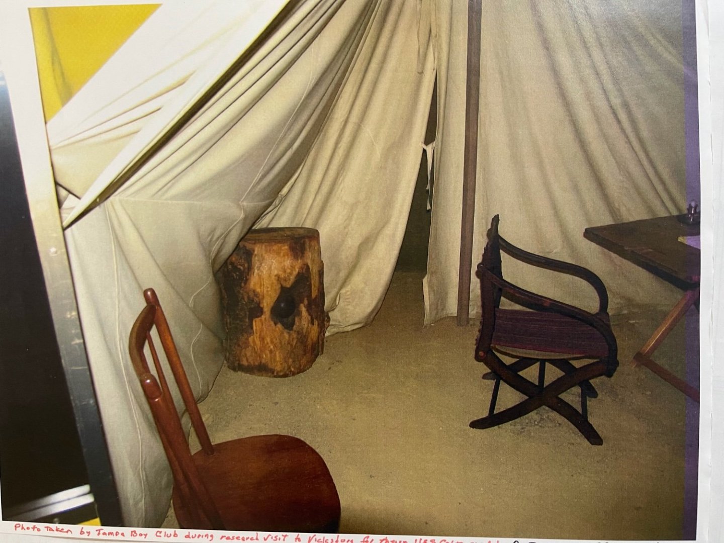
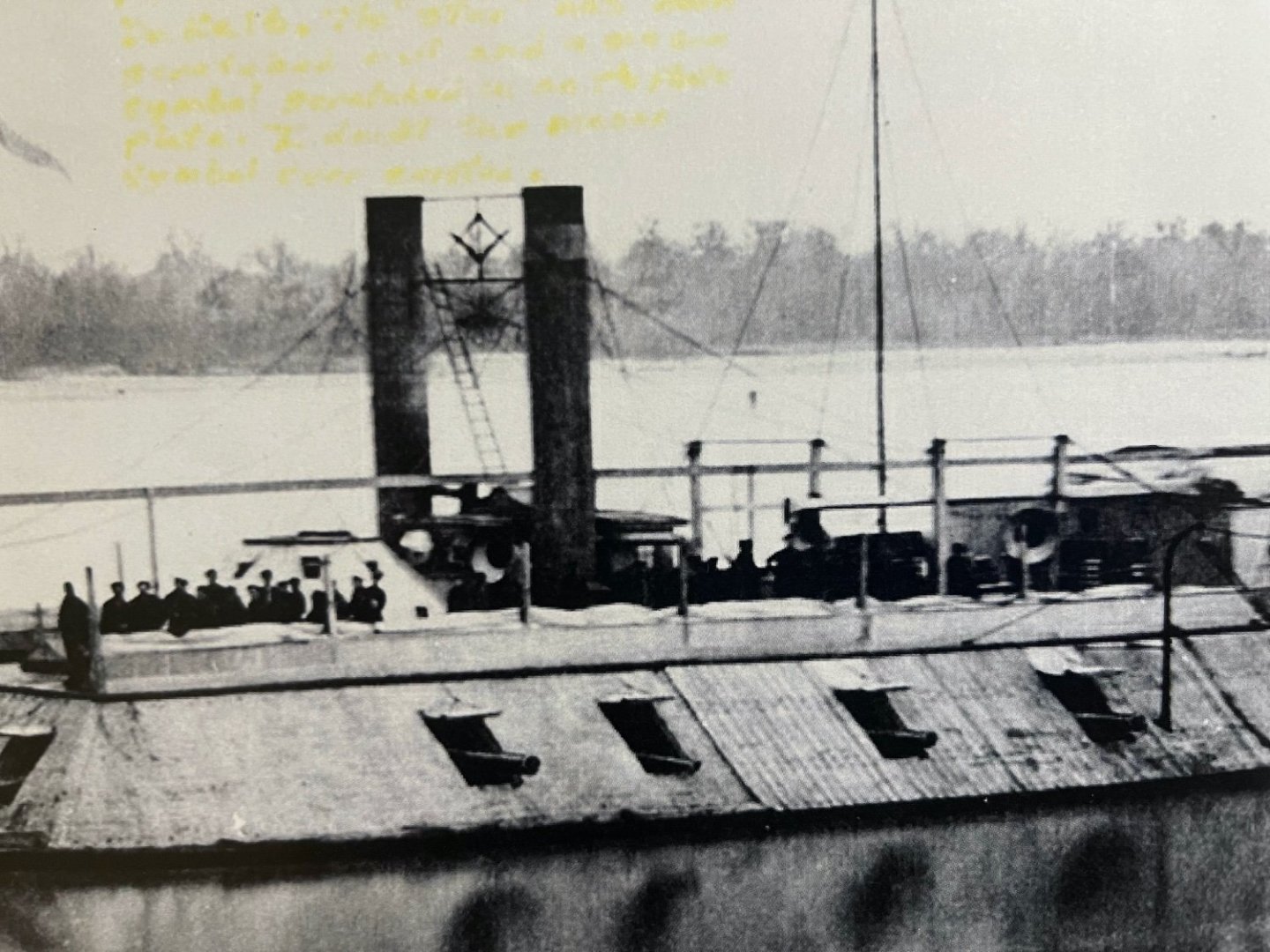
Brian, Congratulations on your amazing modeling effort, including research and maintaining your NRG Forum, in only 2 years. Many thanks for the guided Museum photographic tour. I have attached 2 photos that were included in Bob Hill's Tampa Bay Ship Modelers group Tour from 2012 that appear to me to represent the junior officers quarters on the gundeck under the port and starboard casements. Bob did not provide a label for these particular photos and couldn't remember seeing any placard for them but assumed they were from inside the Cairo museum. (His group consisted of about 10 members and wives, each taking pictures, some under exposed.) I was hoping that you may have seen this display and could shed some light to their intended purpose. Your photos under the decks of the boilers & engines are fabulous compared to those from our "Professional" photographer's visit6 in 2018, so thanks again. I have spent many hours trying to figure out how the two individual engine controls were actually coordinated (Speed and reversal) while connected to a single paddlewheel. Shortly after the CW, a single control design operated both engines. I have also attached one of several contemporary CW photos which supports Doug Ashleys' NPS HSR drawing location for the aft ventilation funnels between the Hog Chain Support Posts, and wonder if you can explain this contradiction. The ventilation funnels themselves consisted of two sections, the lower of which was just a straight tube. The idea was to raise and rotate the flared upper section as necessary to best utilize the local wind conditions and ironclads motion to keep the lower decks.as cool as possible. The overall height of the ventilator is therefore not a reliable indicator of its location when stored. I believe I have even seen a photo of the complete forward funnel leaning against the engine exhaust stack, but couldn't immediately locate it. Your other potential skylight locations are interesting and do deserve thorough investigation. We have previously concluded the temporary removal & relocation of one of the 4 Pitman arm observation skylight next to the Wheelhouse on the USS DeKalb accounts for the skylight on the aft starboard end of the hurricane deck. JOHNHOWARD

-
Brian, Boy you really hit the jackpot this time and your efforts really open the door for lots of additional research. As you know we were always sure there must have been additional access to the Hurricane Deck. Reading your initial trip comment,I had a crazy thought: Is it possible that the access "Skylight" structure you found in your enhanced contemporary CW photographs, where the Ventilation Funnels appeared to be located, just served as a stairway when the funnel was temporarily removed, similar to our earlier "firebox slag & ash disposal from the fireroom" discovery. Ventilation funnel removal must have been a frequent and easy task as several CW photos confirm, and some also clearly show the Funnel large Flange-section between the Hog-Chain Supports and facing outboard as depicted on Doug Ashley's Historical Structural Report (HSR) drawings and NPS Denver Surveys of the USS Cairo.. The Ventilation Funnel in your enhanced photo may just show where it was being temporarily stored when removed from use! An open stairway would temporarily function as an adequate ventilator shaft. These Civil War sailors were apparently very practical. Your descriptions and photos are fabulous and you certainly got the grand tour. Were you able to take photos inside the Museum? JOHNHOWARD