theoracle09
-
Posts
152 -
Joined
-
Last visited
Content Type
Profiles
Forums
Gallery
Events
Everything posted by theoracle09
-
 Hi Bill, @Snug Harbor Johnny did an excellent write-up of Endurance's lines located here back in 2021. Then, when I got to planking mine in Sept. 2023, he posted an updated pic of draft lines located here. I tagged him as well if he'd like to talk about that further.
- 206 replies
-
- 1
-

-
- Endurance
- Shackleton
- (and 2 more)
-
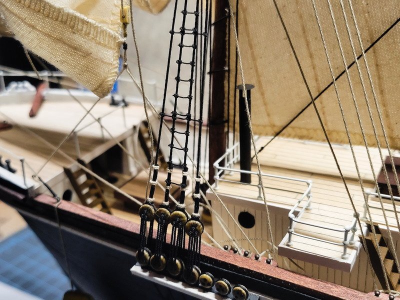
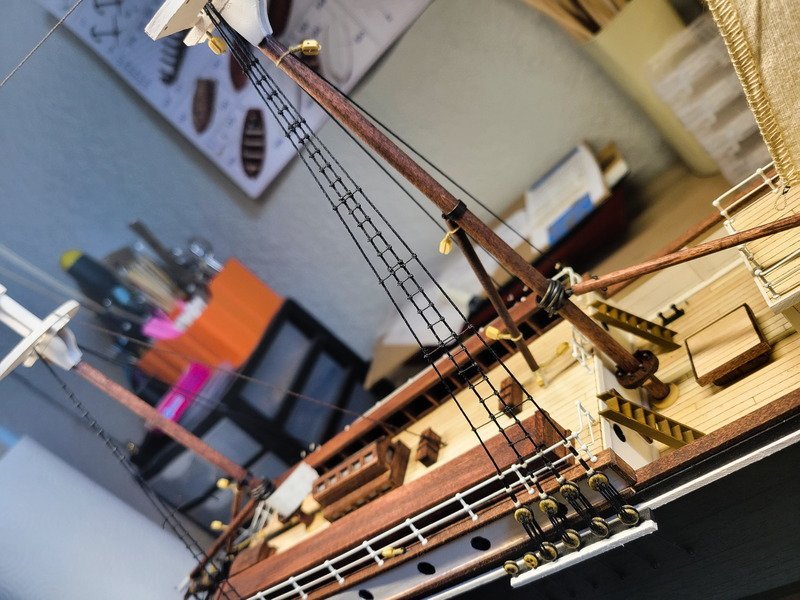
Hi everyone, thanks for the likes and checking in. I'm slowly working towards getting the ratlines complete. The port side main top mast is finished. And the ladder is complete as well. Thanks for stopping in!
-
Hi everyone! Progress is slow, but is still progress. Short and simple update today: the foremast backstays have been completed. Of course one of the lower deadeyes pulled out and needed repair, but no one can tell so no worries there. I'm not super impressed with the height differences in the upper deadeyes, so I'll pay more attention when setting the lower deadeyes next time. Finally I have also completed the lower main mast ratlines. I've slowly been working on a few knots here and there, and it's complete. Thanks for stopping in!
-
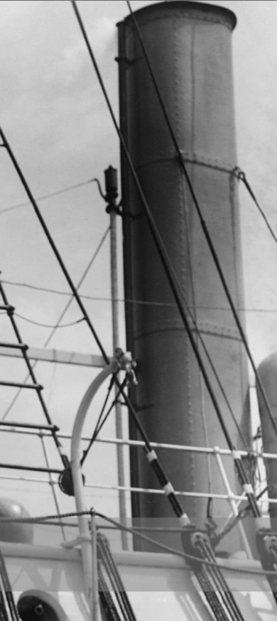
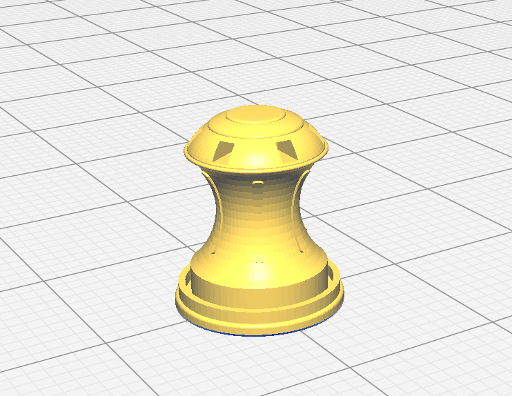
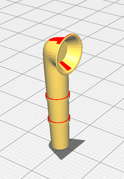
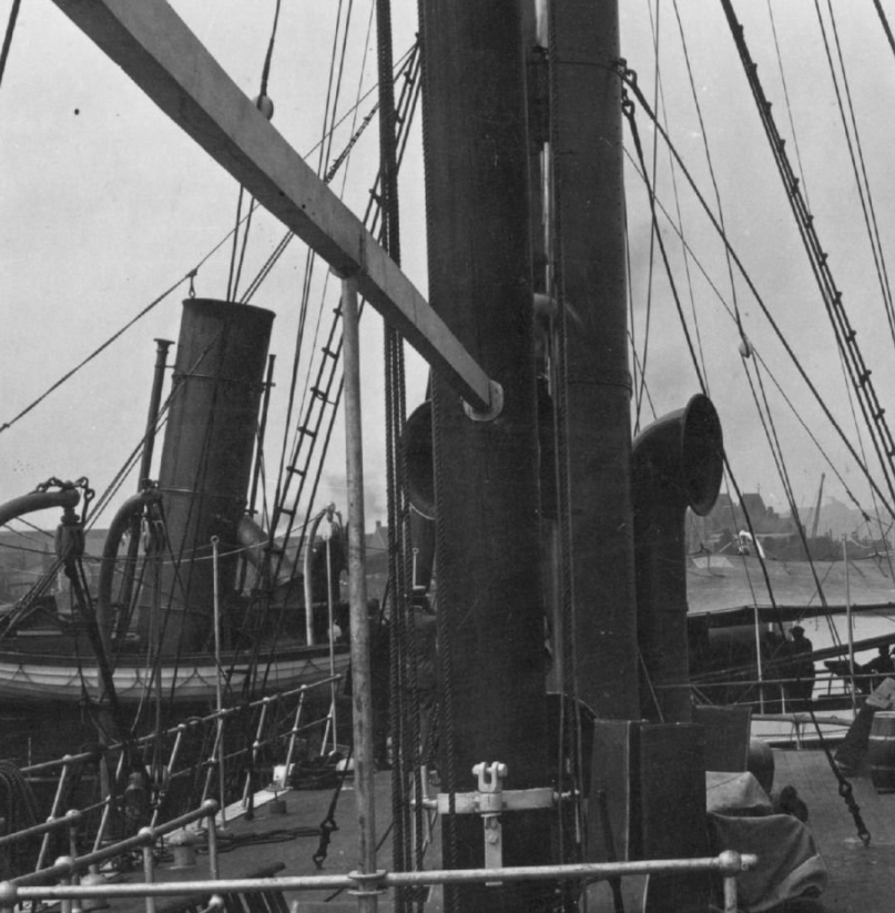
Now that's a nice funnel there. I've really enjoyed seeing your scratch builds for Endurance, it's really cool to see your interpretation of each assembly you're bashing. I'm not sure why OcCre decided to make it a bent pipe. I have this reference pic though which shows the pipe to be a whistle I believe.
- 206 replies
-
- 2
-

-
-
- Endurance
- Shackleton
- (and 2 more)
-
Of course! In my opinion, 3D printing is the way to go if someone is after ultra-realistic historical accuracy. Searching the web for obscure parts 10 years ago was vastly different than it is today, and I find it more difficult to obtain these items nowadays. Which is weird, considering the leaps in technology and people making their own stores on Etsy or wherever else. The point is, with a little bit of time to learn a 3D modelling program, it's quite viable to model and print your own objects. I have a main website I've gone to over the years to obtain knowledge on 3D printing. First, a primer on the difference between FDM and resin printing should be understood. Long story short: resin printing is more suitable to smaller models. FDM (such as Ender and Prusa printers) leave layer lines that need to be dealt with in post-processing, and the print becomes less consistent at smaller models. Resin on the other hand produces smooth, tight results much better suited to model building. Knowing that resin is the way to go now, here's another article on resin printing. It goes over the technology differences between SLA, LCD, etc. At the bottom, it lists some recommendations for printers sorted low to high. Of all the research I've done, an Elegoo Mars is what I would purchase if/when I'm ready to buy a resin printer. I currently have an FDM (Ender 5 Pro) so I can print bigger items, like the smoke stack, but not the capstan and other smaller things. I've found the Elegoo line to be reliable from my searching and is even the brand @Hunt270 uses. He could chime in more on the resin side of things if he'd like. All-in-all at the time of typing this an Elegoo Mars 4 is currently $269. Not bad at all in my opinion. The thing is, you need other items with resin as well, like a washing and curing station. These two items can be found bundled on the 'Zon, or on Elegoo's site directly. It increase the initial cost to get into it, but once you have them you'll find you can model and then print whatever you want. If you have amazing photo reference pics you can model the object and print it out and be the only person on the planet to have that 'thing' in your model. Unless you share your models, of course. I hope this helps! A bit lengthy, but I wanted to include as much detail as possible.
-
Thank you for the kind words, @Cenizas ! I would absolutely love to see another Endurance model around here so I would highly recommend you start up a log! I'd like to provide a link to my first log, an AL San Francisco. Unfortunately, the beginning of the log fell victim to MSW 1.0 and I don't have pictures of when I started planking. Believe me when I say, it was a mess. My point is, it was because I started the log that I was able to remove my first planking attempt and do it the right way. I didn't have any more anger or frustration during the task, and found planking to be an immensely cathartic experience. Now ratlines on the other hand are a totally different story! I've learned so much by showing my representation of Endurance, it really is awesome having folks stop in and make comments, corrections, suggestions, etc. Had I not created this log, I don't think I would've been pushed to create her the way she sits now. If you do decide to create a log I'd love to follow along!
-
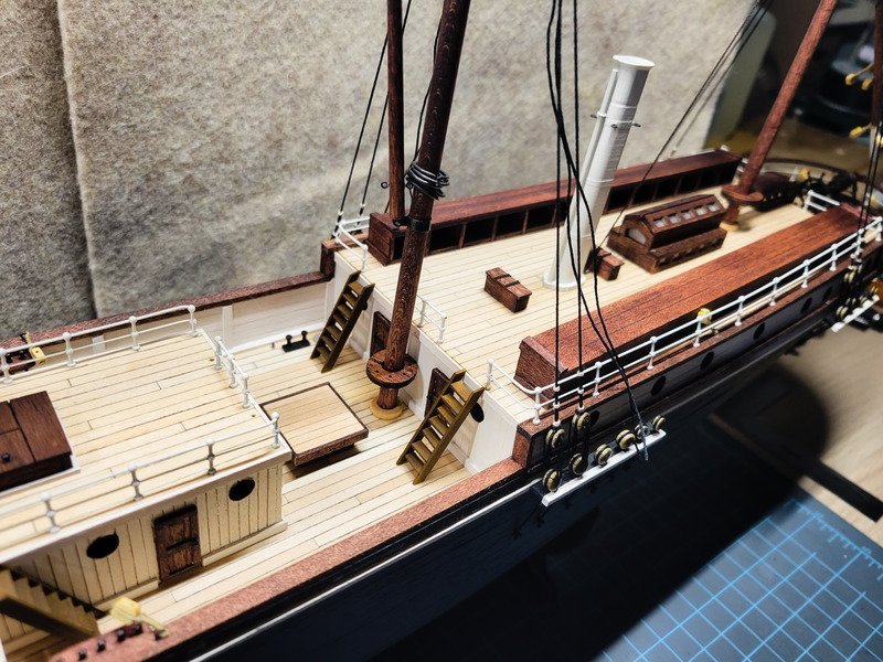
Nice progress on the ladders, Tom. I remember having a tough time creating the wooden ones because I didn't use a jig, and it shows if you look at specific angles. Instead of re-doing them I'm banking on other details drowning out that one and it not being as noticeable. For the count of ladders on the aft deck, I have one pic which shows two ladders being employed at some point after Buenos Aires. The port side is odd, the sides extend well passed the mizzen deck. I'm not sure which time period you're representing so this may not be relevant.
- 206 replies
-
- 4
-
-
- Endurance
- Shackleton
- (and 2 more)
-
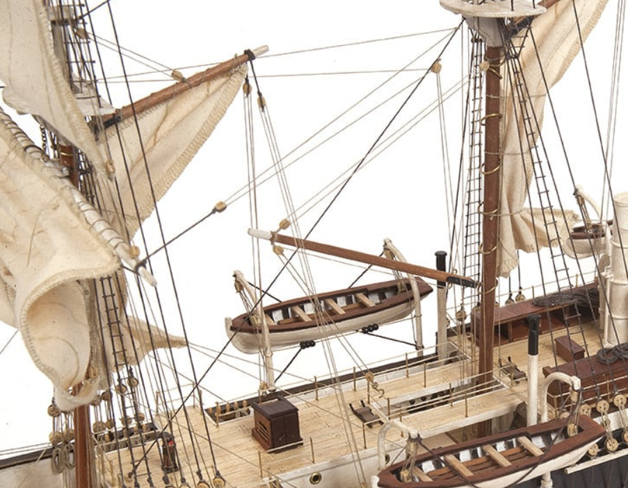
Now THAT is cool as heck. I especially enjoy the black ropes wrapped around the block hooks and the anchors. Very impressive! I have to ask, did you make those hooks? I really like the look of them. Also I've had a burning question for the last week and while I don't want to question your method, I'm curious about the bow pin rail and the 5 pins you have installed. I just belayed that area a couple weeks ago and I have 6 pins there to hold the 3 down haulers and 3 tack lines for bowsprit sails. Do you have a plan for the 6th rope coming from those sails?
-
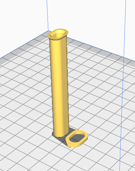
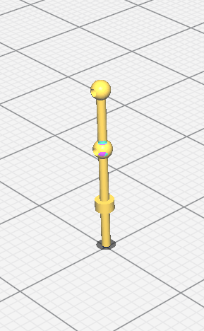
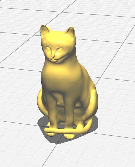
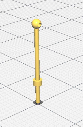
Hi Andy, welcome to MSW! If you plan on creating a log please let me know and I'll follow along. I really enjoy seeing other's interpretations of Endurance. I've attached the STL of the funnel to this post, you should be able to download it and give it to anyone with a printer (resin or FDM, doesn't matter). This model has two parts, the main funnel and the base. SmokeStack.stl I'll go ahead and attach the other models I've made, just in case you or anyone else would like to download them and use them for their project. CapstanCombined.stl CapstanHandle.stl MiniSmokeStack-3.stl. Stanchions_01.stl. Please note: These are not the stanchions you see on my model. I used 3D brass instead of the 2D brass that came with the kit. I modeled this for Will as he has a resin printer and will print his out. I'll include it in this post, but do note I did not use this. Single ball stanchion.stl. Same thing here, the single ball stanchions seen at the bow of my model are brass. This was just modeled so if you couldn't find the brass ones in stock anywhere and had a resin printer sitting somewhere close you wouldn't have to use the 2D brass ones the kit comes with. Chippy Model_05.stl. I haven't shown this in my log yet, but I did make a Mrs. Chippy to place somewhere as an easter egg of sorts. He (yes, the tabby cat was a male. The crew kept calling him Mrs. Chippy anyway after they realized the mixup) will be placed on at the very end. I decided not to place dogs on the deck so won't be modeling any of those. I hope these can help! SmokeStack.stl CapstanCombined.stl CapstanHandle.stl Mini-Smoke Stack_3.stl stanchions_01.stl Chippy Model_05.stl single_ball_stanchion_02.stl
-
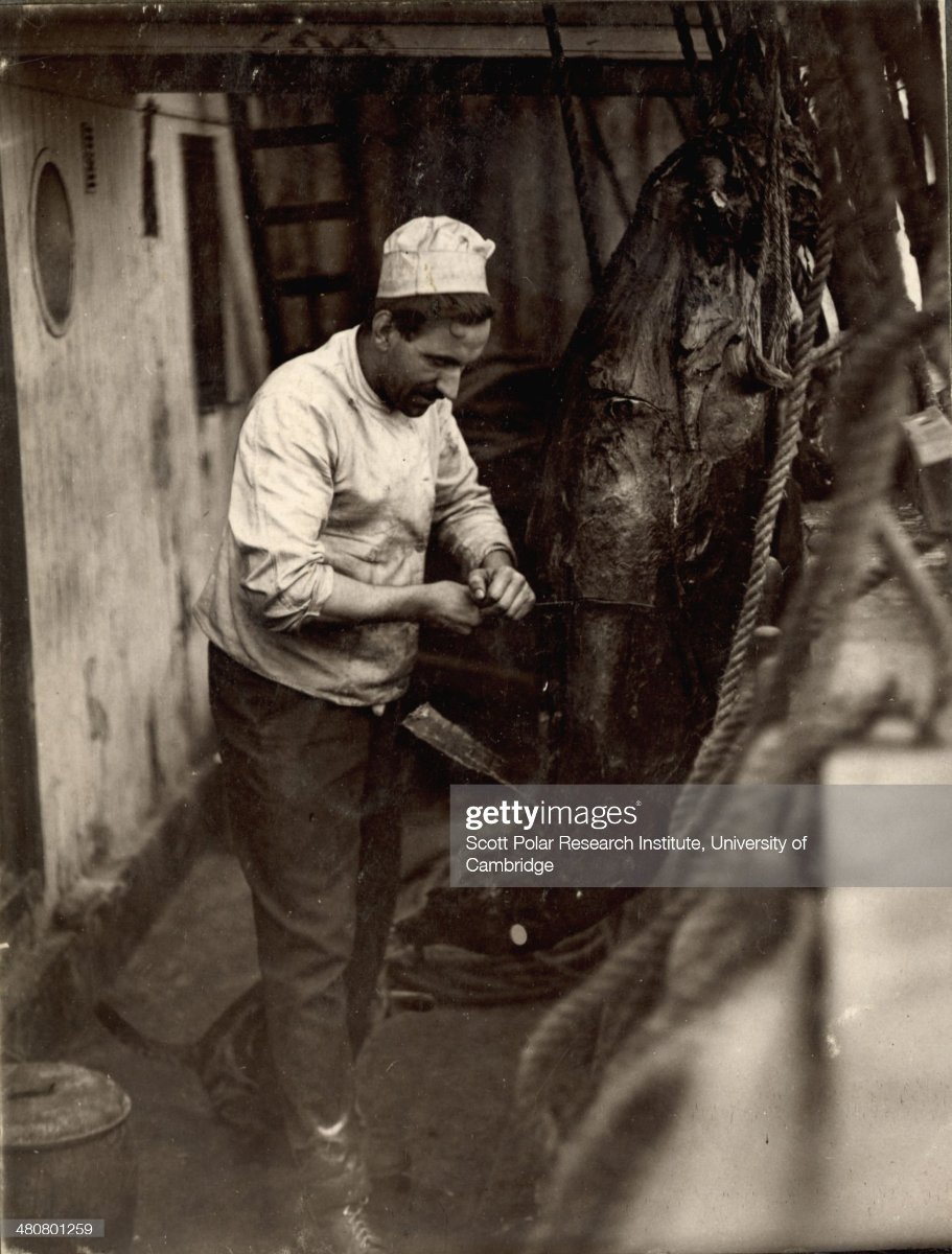
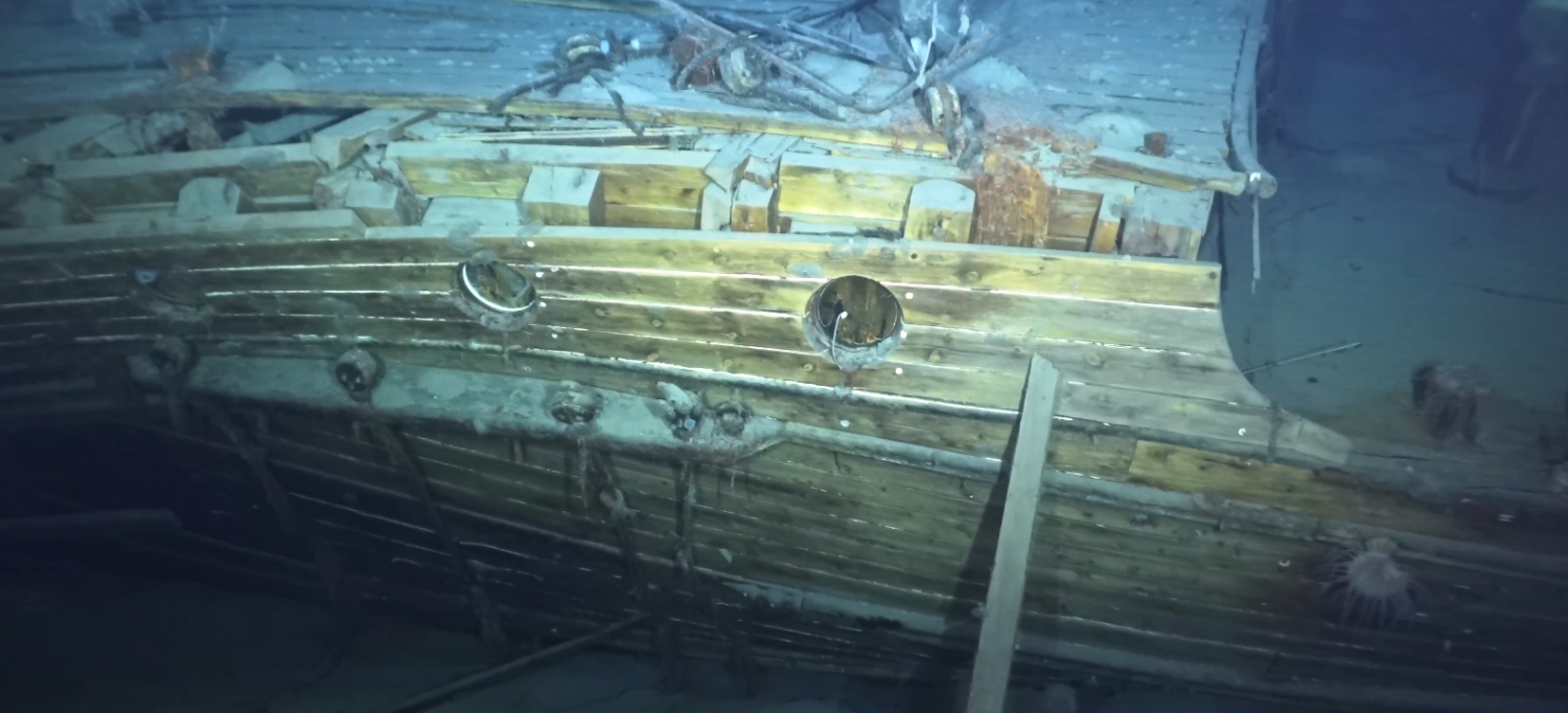
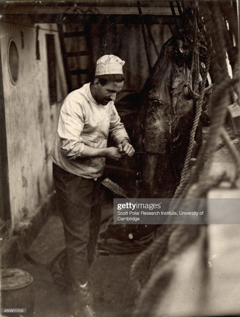
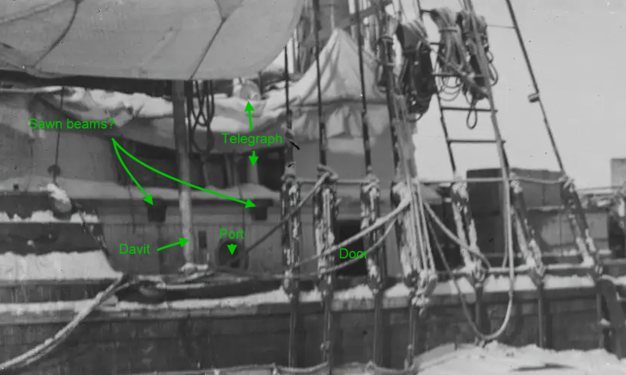
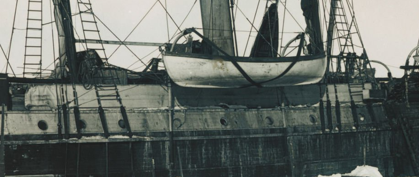
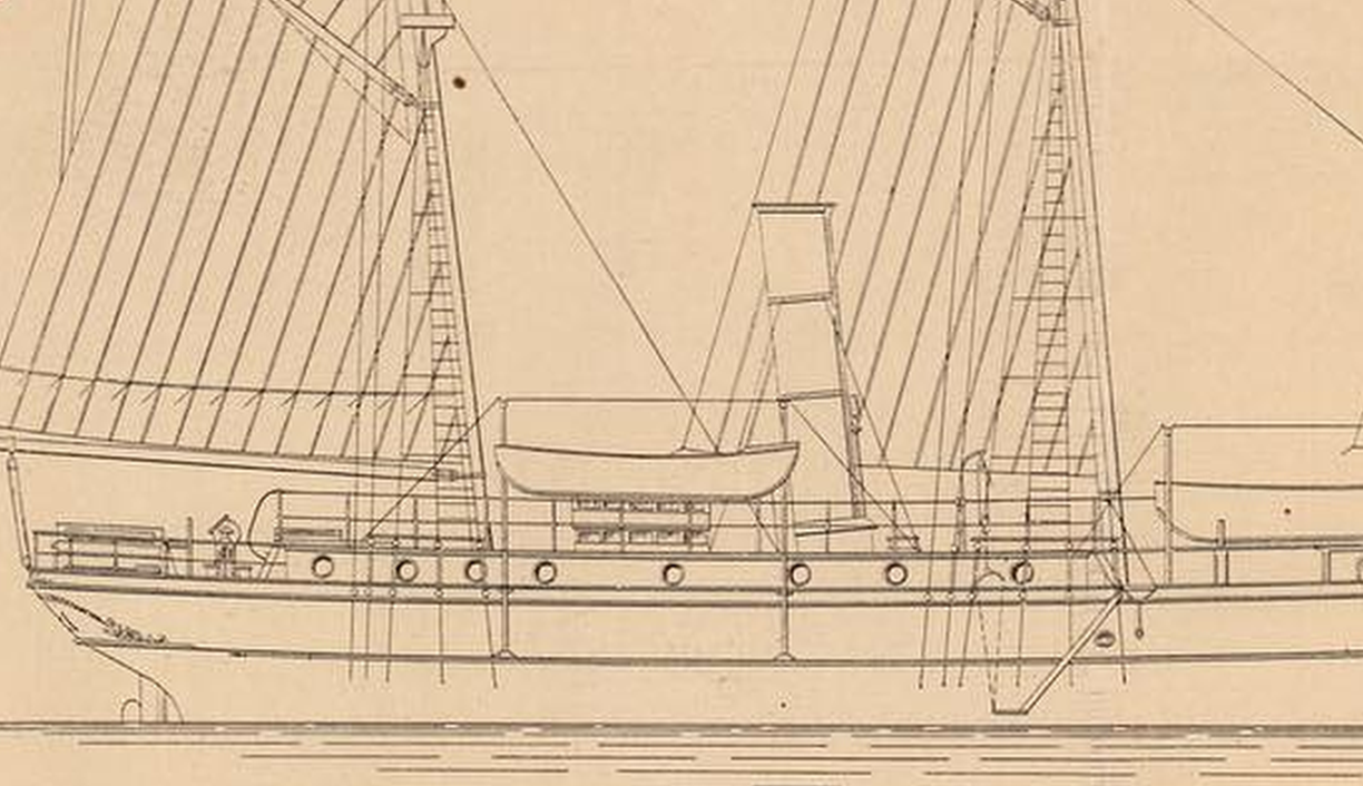
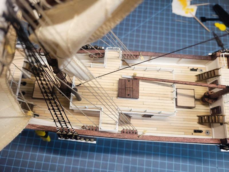
This is what started my entire journey into researching Endurance. I was just browsing a catalog to buy my next project and immediately zeroed in on those gangways. What a neat detail, and one I haven't seen on any other ship (mind you I'm not well versed in ships. I'm sure other ships have gangways I just don't know what they are!) So with the kit in hand and after reading other build logs I decided I wanted to be historically accurate. I wanted to model her as she was in the ice, but that included the deck extension, thus removing the entire reason I purchased the model to begin with. A decision had to be made and I chose to keep the gangways and not deck that space. Keeping the gangways but including the kennels is representing a hybrid configuration of sorts, as I don't believe she would have had the kennels until after the extension were in place. This pic isn't under the extension, but does show a little detail from the quarter deck: This image seems to line up with Ken Greenwood's model, pictured below. I believe the cook to be standing on the port side, so we're seeing under the wing of the bridge, including the ladder. However it doesn't really show if it was decked, sheeted, is there a door, etc. But also note the square porthole on the quarter deck house, which is not in OcCre's plans. In the pic of Ken Greenwood's model above, the starboard wing is missing. That also lines up with @iMustBeCrazy 's post here in my log that shows this picture: So there are an absolute ton of details to upscale and kitbash with Endurance. It's been an amazing and fun adventure researching and building her. Do you have a link to this photo? I was able to download the entire released video of the wreckage found that's 1:33 long. I emailed the expedition company and asked for (at the very least) a still frame of the area around the main mast and they told me I had to wait until they've put something together for the media. I didn't get a timeline on when this would be released, but I'm on their email list. I suspect when it is released though, it'll show us more details and can hopefully answer more questions. Back to this photo though, I don't see anywhere in the video that a still frame could have been taken that shows this deck extension missing. The closest I can find is this: However, this looks more to me like the port side mizzen lower deadeyes, showing a deck transition from mizzen to aft decks. There are three portholes behind the lanyards, and the main mast had two portholes. The below pic is when she was stuck in the ice, starboard side. I count 8 portholes as well, and the plans seem to match up with this number too. I went a bit off topic from the kennels, but hopefully this helps demystify that deck extension. There are definitely many routes to go when modelling her that's for sure.

-
Excellent write up Tom and one that I appreciate very much as I haven't looked into the anchor situation yet. I installed the eyebolts on the cats and decided to stop there because it didn't make sense to secure the anchor rope to them. I'm interested in seeing what you've come up with, as I think I'll also create a portable davit for the anchor deck.
- 206 replies
-
- 1
-
-
- Endurance
- Shackleton
- (and 2 more)
-
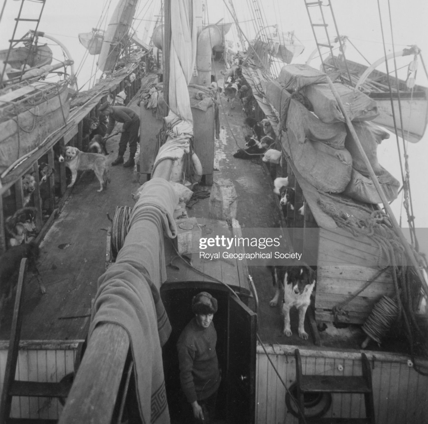
Craig hit the nail on the head here. To be honest, I didn't consider changing the kennels so I never researched or thought about it. Here's another pic to toss in, though. One thing which has been extensively discussed in my build log would be the deck extension when they refit in Buenos Aires. Which is also when they added the kennels. There are several pics, including a video on YouTube, which shows the kennels not just on the mizzen deck, but on the quarterdeck house (or bridge deck) as well.
-
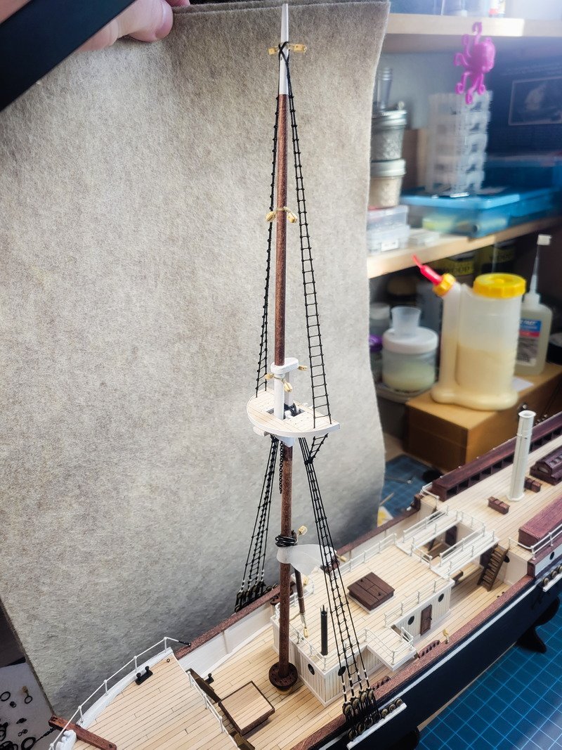
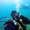
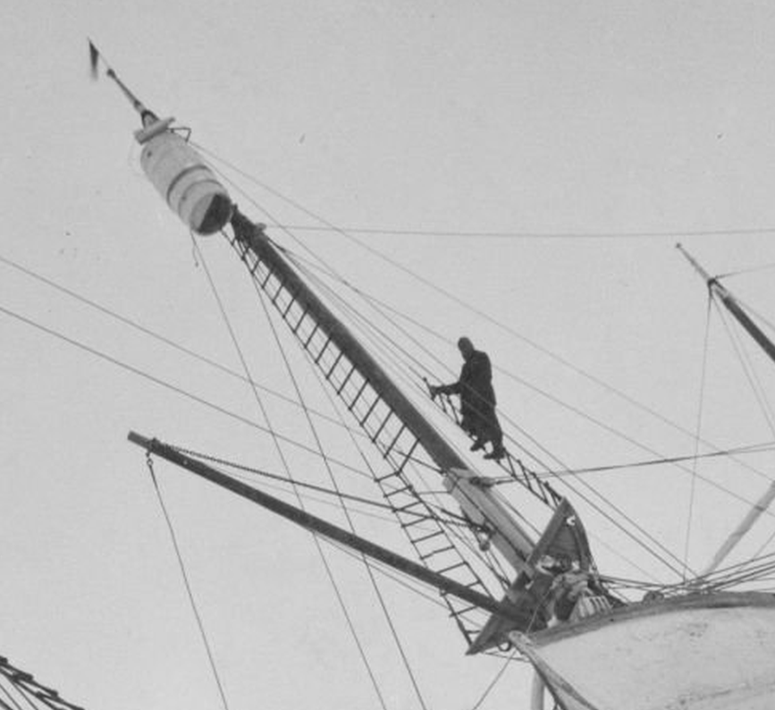
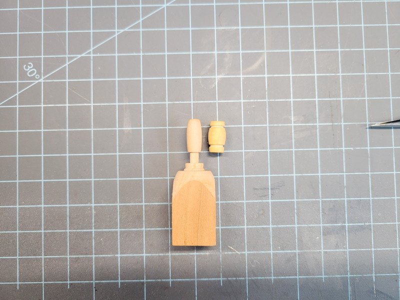
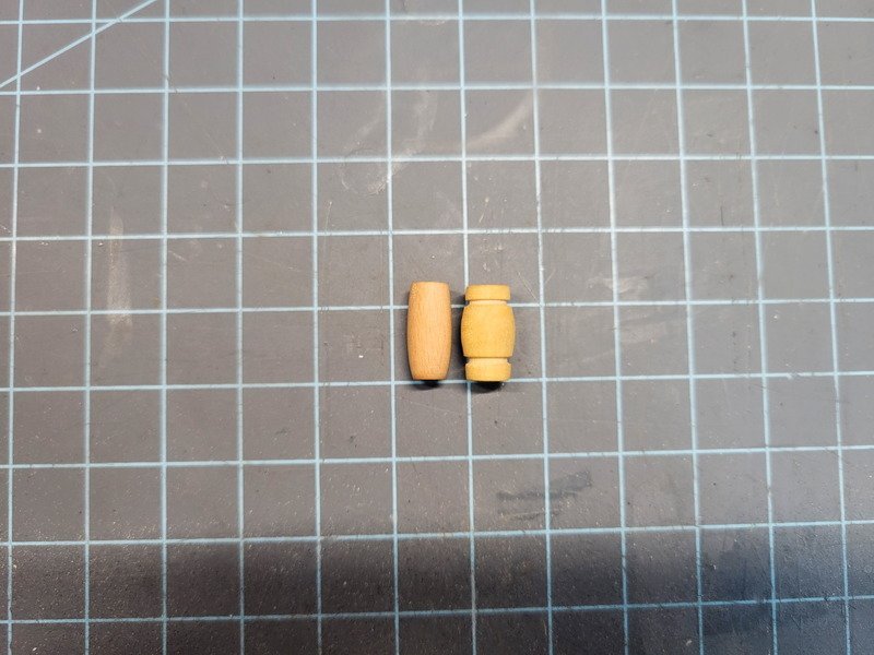
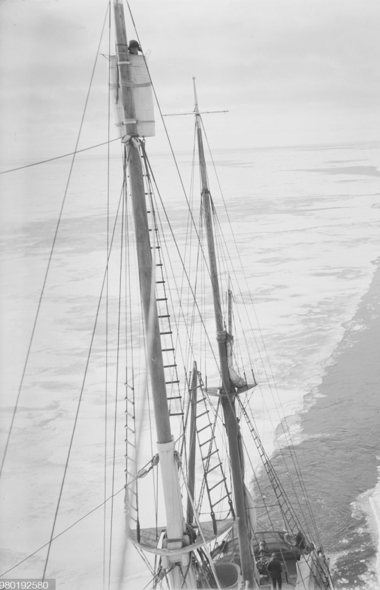
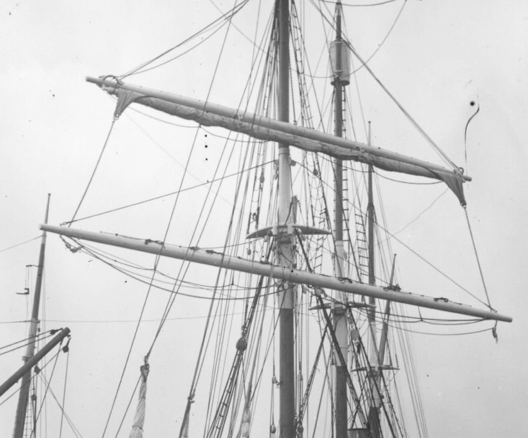
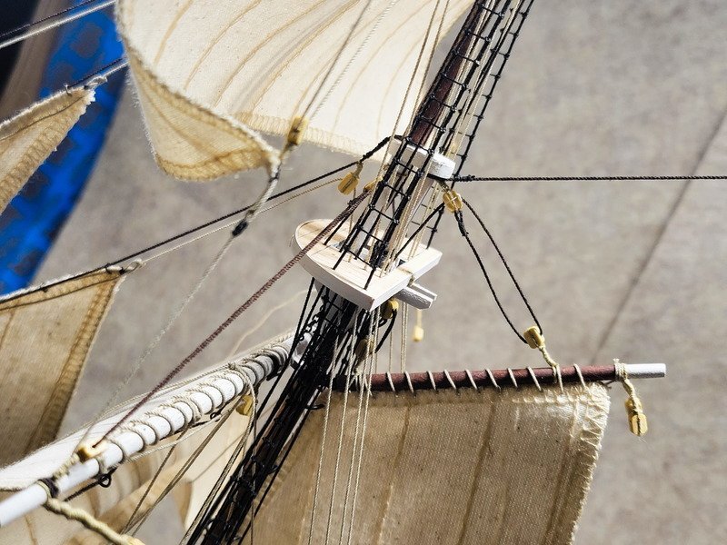
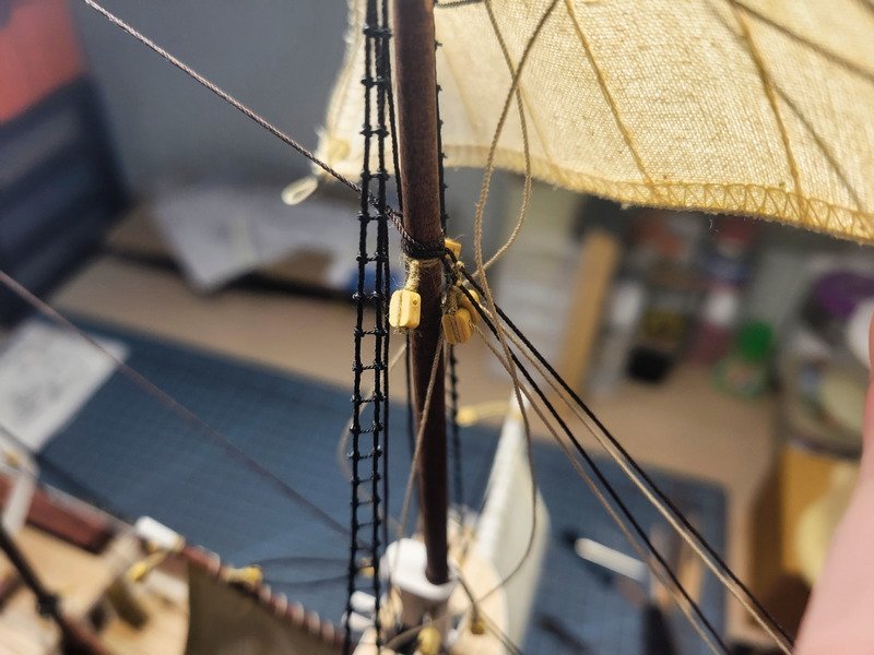
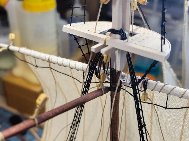
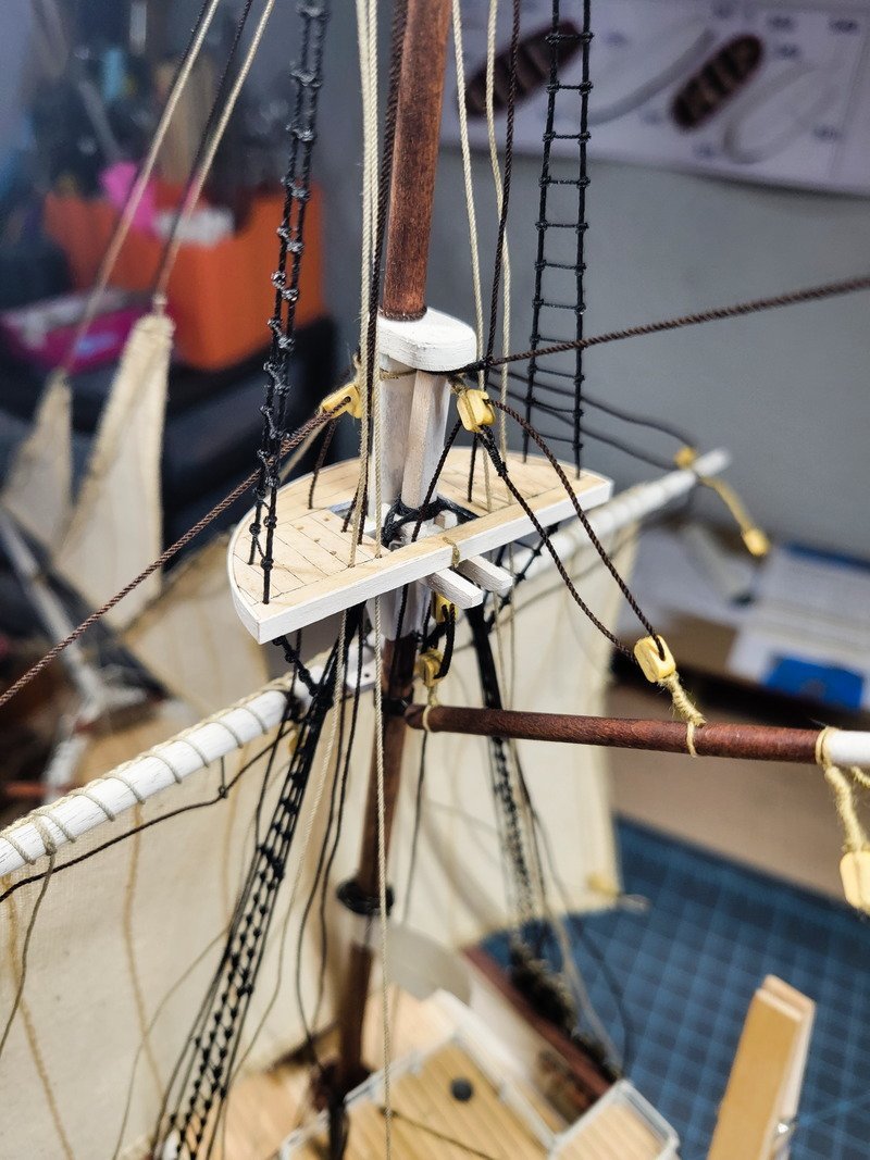
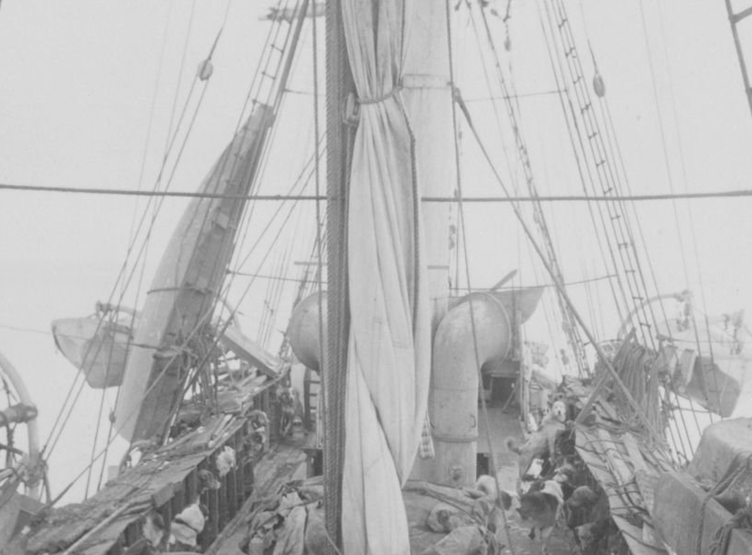
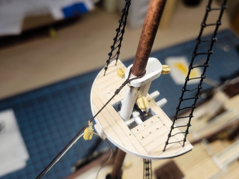
Thank you so much for the kind words! I would love to follow your log and see your interpretation while building her, I'll keep an eye out for when you start! Thanks Tom, I've decided that's the route to go. It'll be unique, and I really enjoy unique ships. Excellent summation Johnny! I always learn a lot from your posts so keep them coming. I actually assumed the sailors would clamber over the top of the crows nest. After seeing your explanation I went back to the reference photos and found exactly what you described. An excellent shot of the main top mast, including the bottom of the crow's nest. Hi Jim! That definitely doesn't sound fun! I'll have to check that book out. ----------------------------------------------------------------------------------------------------------------------------------------------- I ran into some issues getting the fore mast sails adjusted. The two double blocks used on the lower top sail yard were not glued with thin CA, just fray check. I didn't even think to brace those blocks while pulling on the lines, so they slid out a bit before I caught it. I don't have a picture of them, but if I were to pull on them any more they'll become detached from the yard. I'm not taking the chance, so the lines are staying the way they are. I'm happy with everything except the upper top sail sheets. They could be more even, but for my first rig job I'll accept it. The lower top sail sheets can also be a little more even, but since that lines goes through the block I talked about, it's there forever. With the adjustments done (including the bunt lines, I tightened those up) I glued and cut the loose ends. Since I don't need to access the quarter deck belay pin rack racks anymore (I mean, I'll hang some coils, but I don't need to belay lines) I went ahead and secured the starboard fore mast back stays. A small note for future me: pay attention and confirm lanyard sizes before lanyarding. I haven't done lanyards for a couple weeks now and between thinking of all the things I forgot what size rope I used for the rest of them. For the third lanyard from the left, I used 0.3mm and glued it before I realized things weren't quite what they should be, which is 0.5mm. That's why it's twisted a bit as well. I considered cutting it out, but I used clove hitches on the masts themselves so I have two working ends to tie the lanyards to. Which are glued. Needless to say, it's on the starboard side and I don't think anyone can really tell anyway, especially behind a case. In the next pic you can see the two double sheave blocks on the lower top sail yard which slipped. They're only being held against the yard by the robbands. If I tug on those lines any more, those blocks will slip all the way out, and I'll really be in trouble. After seeing everyone's post and making up my mind I started figuring out how to build an aft top mast ladder to the bottom of the crow's nest. I added 4 eye bolts to the main top mast. The upper shrouds have a distance of 9mm between the holes, so I did the same for this aft ladder. The upper eyebolts are 11mm aft from the drilled hole in the mast top. Before proceeding with the main mast upper shrouds I wanted to figure out the crows nest first. I knew right away I didn't want to use it because it's incredibly bulbous. I ended up turning one on the lathe and came up with this. I don't know the species of wood it is, but it's a cut off from a pen I made at some point. I don't know why I didn't get a pic of it, but I drilled a hole all the way through the middle. Including the bottom. I spent some time trying to come up with a way to emulate the reference pic in the beginning of this post, but I didn't really come up with anything. I wanted to make the half-circle shape to show half of the "floor" of the crows nest being hinged up, as if no one was currently in the nest. I decided the detail isn't worth it, as no one is going to be crawling on their knees to view the bottom of the crows nest. Since the hole goes through the entire thing I'll explain it away by saying there's a door in there that's hinged up and when a sailor climbs up through the bottom they'll close the hatch, or floor, and be able to hang out. Thanks for reading along!
-
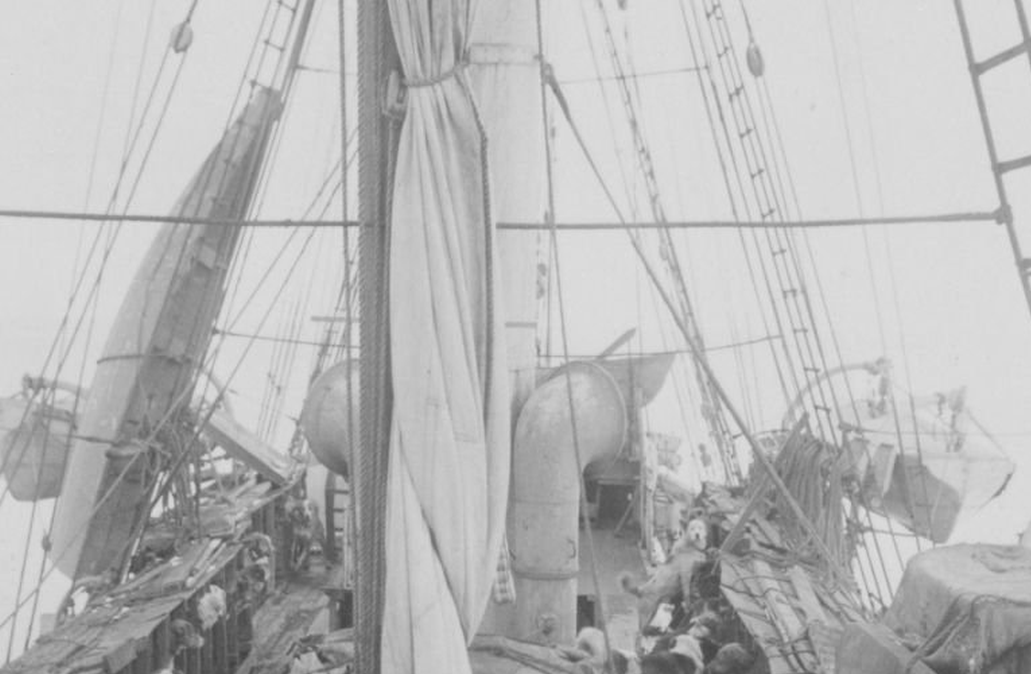
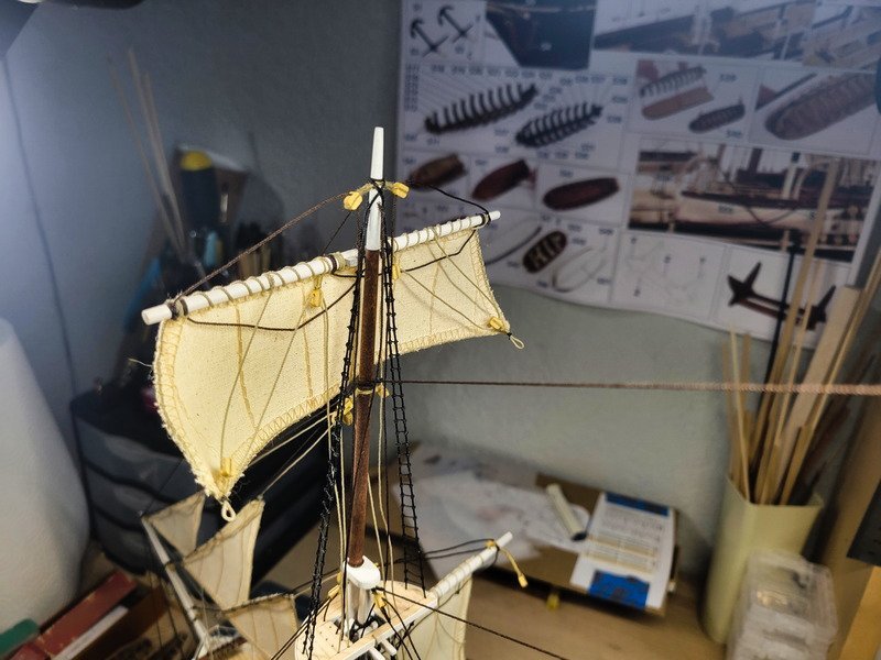
Hi everyone, I don't have an update for this post but do have a question. I'm checking the plans for the next several moves and I'd like to tackle the crow's nest next. I found this awesome pic for reference: The first thing to note is the crow's nest supplied with the kit doesn't look like what was actually on the ship. Since I have a lathe, it'll be extremely easy and fast to turn a new one, so that'll be the plan. However, once my eyes landed on the upper shrouds I stopped in my tracks. The ratlines (ratlines being the rungs of course) only go up half way, and the mizzen upper shrouds don't have any at all. There's also a (ladder? I'm not sure what to call it) on the aft end of the main mast top which seems to connect to the fore edge of the bottom of the crow's nest. So my question is: would it be weird to model it in this way? Leave off the mizzen upper shroud ratlines, run the main mast upper shroud ratlines about half way, and create a (ladder?) to the crow's nest. I'm definitely leaning towards doing this because: 1. I don't think I've seen anyone model Endurance in this way, 2. it's a LOT less work due to less ratlines, and 3. it's unique and unusual. ** Post edit: Number 1 above is incorrect. Ken Greenwood modeled Endurance in this way. Here's a pic of her in London in dry dock that also shows the same things. It looks like whether she was in London or after her refit in Buenos Aires she had always been rigged in this way. I'm definitely leaning towards going this route but wanted to see what other folks thought. I appreciate any opinions!
-
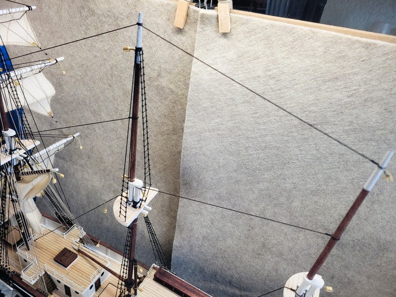
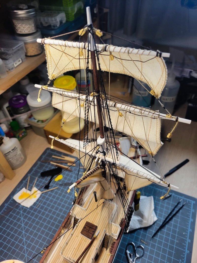
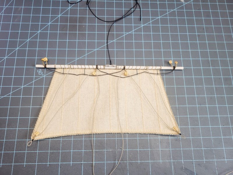
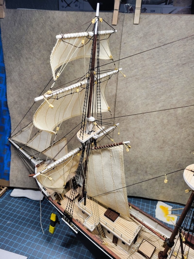
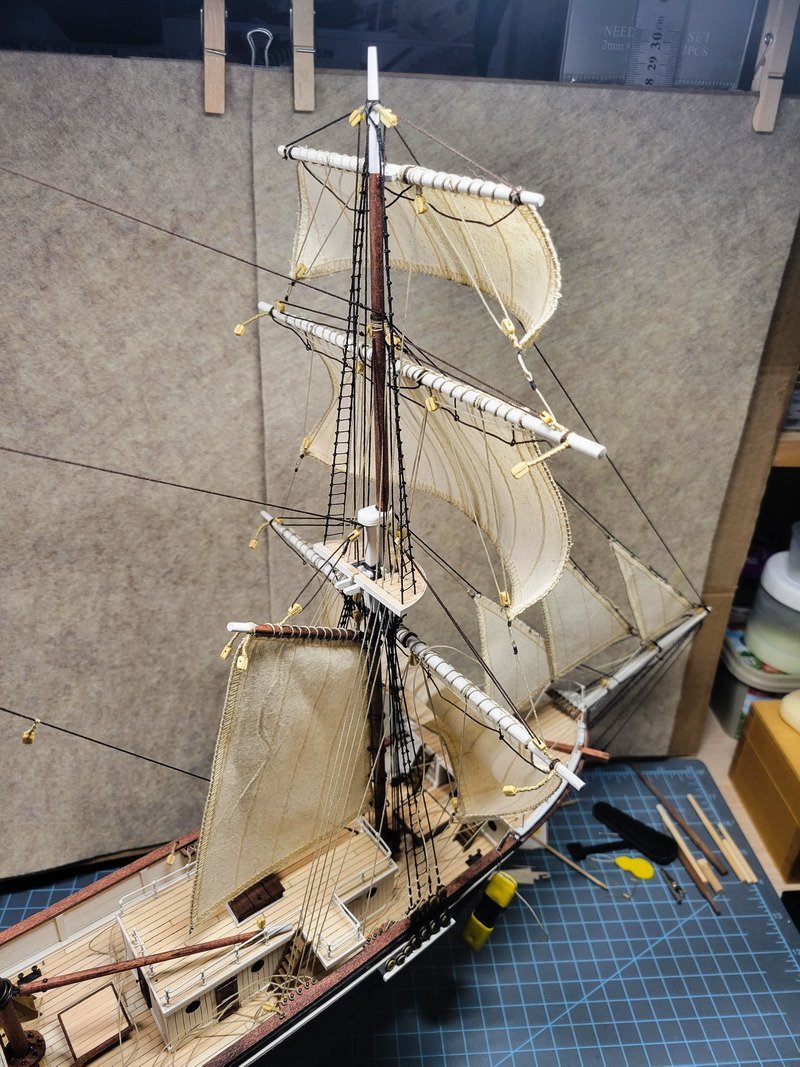
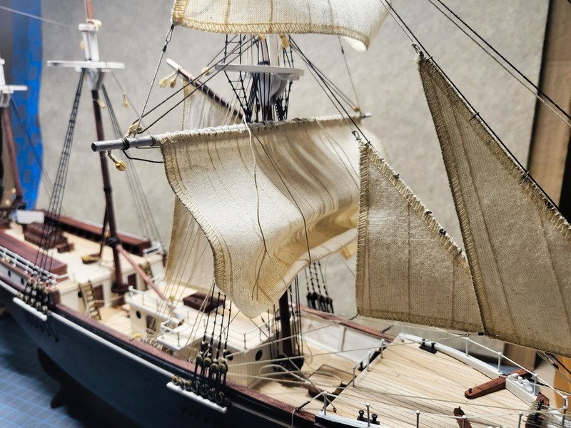
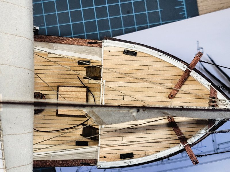
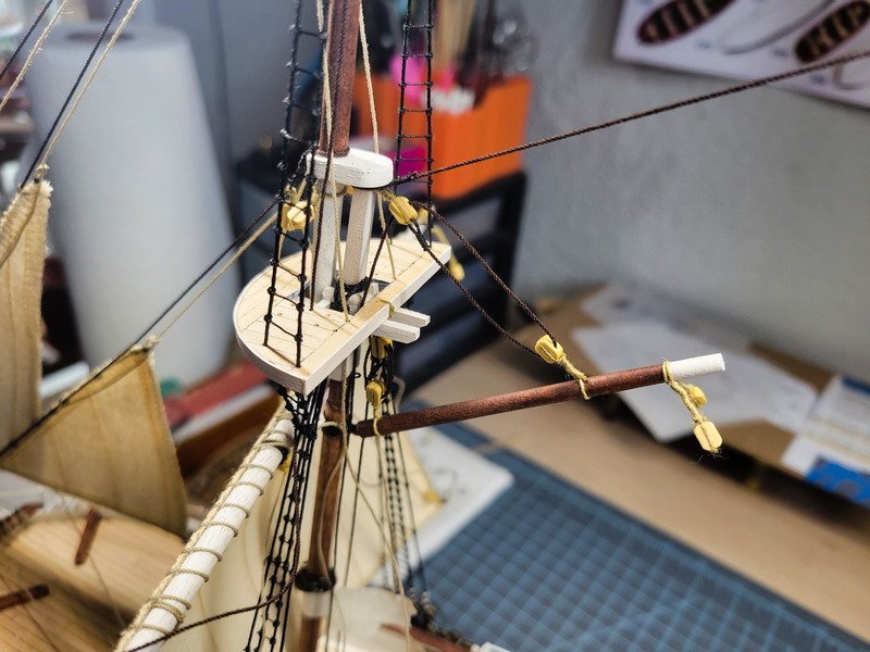
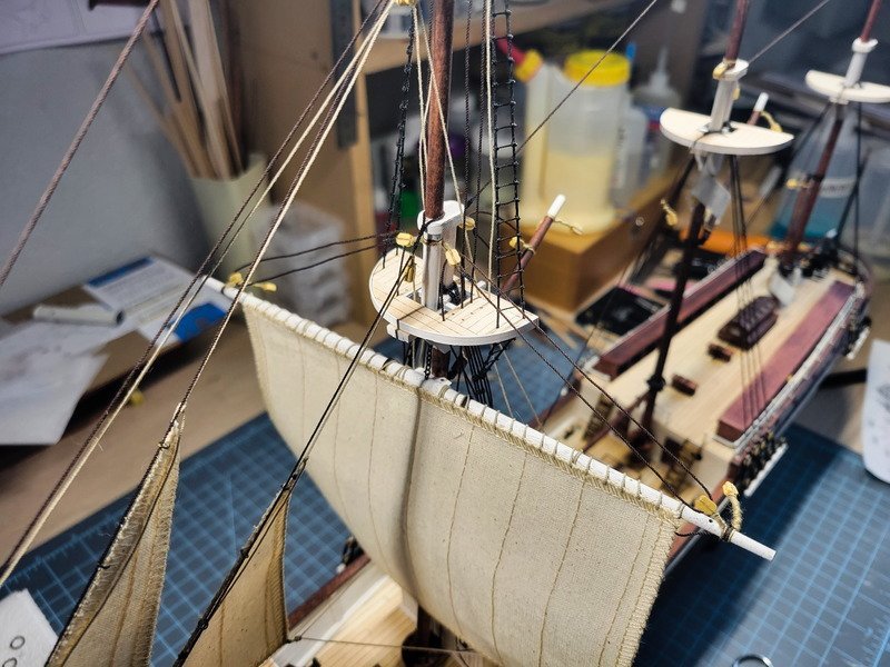
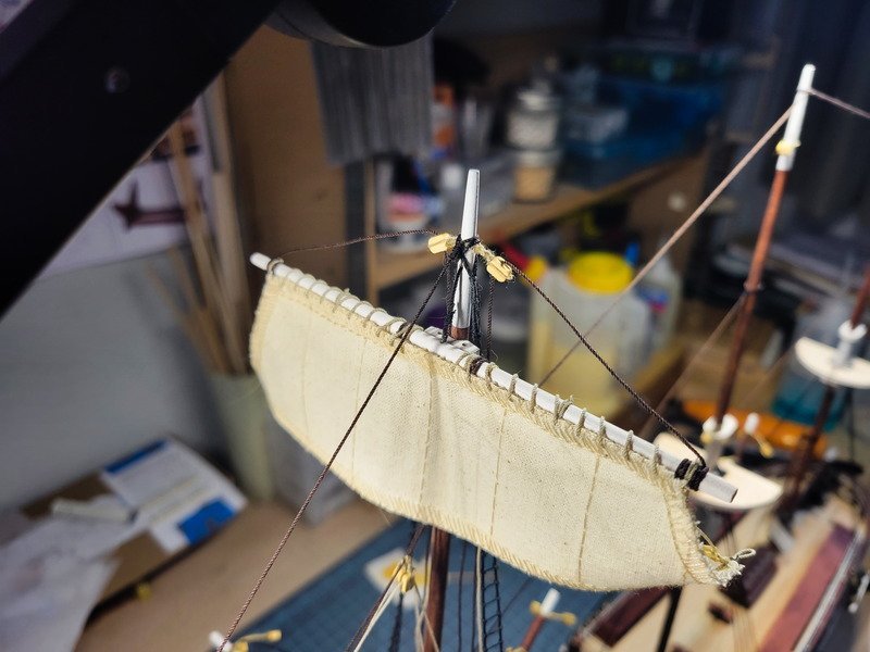
Hey everyone! I've been able to progress along the foremast to almost completion. The day began by completing the lower topsail and getting it into position. The sheets were seized by tying a ton of overhand knots, similar to all the others not done on the seizing machine. I started with the upper topsail sling and belayed it to the mast pin rail. Next the upper topsail lifts, lower topsail sling, lower topsail lifts, and finally fore sail lifts. With the standing rigging done I could start shaping the sails and belaying to the port and starboard pin rails. The running rigging hasn't been glued and trimmed yet so I still have an opportunity to shift some things around. An example is the port side sheet for the lower topsail is about a cm longer than the starboard side. I'll need to release a bit of the clew and take in a bit of the sheet. Additionally I think I want to tighten the fore sail bunt lines and add them to the lower top sail. The next pic shows the starboard upper topsail sheet needing to be taken in as well. The yellow clamps in the pic above are holding tension on the fore sail forward sheet. Trying to get a seizing in there is going to be a task, so I just left the clamps for now until everything else is tightened up. Starboard side details. Thanks for coming in!
-
Thanks Keith, I even have a bottle of diluted pva made up. I've been having excellent luck with fray check as there's virtually no stiffness once it's dried. I'll have to give pva a try too and see if there's a difference. --------------------------------------------------------------------------------------------------------------------- Hi everyone, happy Wednesday. Thanks for the likes and comments! My last update talked about the fore gaff sail, so let's take a look at that first. The brass rings are rather soft so it was easy to remove them from the mast. I used a blunt tapestry needle to make holes along the forward edge then inserted the rings. I was able to use needle nose pliers to manipulate each ring on to the mast while ensuring the 3 ropes already belayed weren't inside the rings. Final step was to sew the robbands and that wasn't difficult either. One thing I noticed is the fore gaff sail and the main gaff sail seem to be the same size. The plans are not the same size, though. In fact the sails are almost 15-20% smaller than what the plans show. The plans also show a difference in the main gaff sail and fore gaff sail, so I'm wondering if I received two of the same sail or something. On others' models the fore gaff sail is quite a bit above the bridge deck, whereas mine here is only a few mm's above the railing. I don't see this as being an issue however, because it's going to be displayed furled. After installing the gaff sail I went back to ratlines. The starboard main lower shrouds are complete and the mizzen still needs a few more there in the middle. Lastly I was dry fitting the lower topsail yard and realized the flying jib and jib sail halyard needed to be scooted up towards the mast, otherwise the ropes would be in front of the sail. Luckily I didn't use thin CA on them so they moved easily. Thanks for reading along!

-
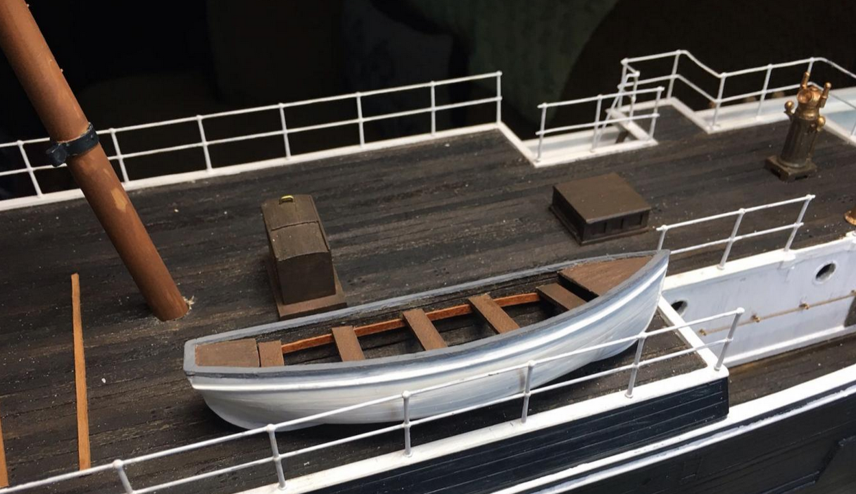
Coincidentally Clearway brought this up in my log last week. My assumption is when they extended the mizzen deck at Buenos Aires they moved the connections from the bottom of the main mast to a rail on the shrouds. In the pic above you can see rope hanks hanging on the starboard side. For the port you can see it about a quarter of the way up on the skiff.
- 206 replies
-
- 2
-
-
- Endurance
- Shackleton
- (and 2 more)
-
Thanks Hake! You know, I do remember this advice and completely disregarded it because I switched to pins instead of eyebolts. Inexperience told me it'd be fine wrapping the ropes around the pins using a tool outlined in Ship Modelling Simplified. It works amazingly well when the pin is facing me, even with tweezers in the other hand and all those ropes belayed already. But when it's between two objects, yeap, it should've been tied off first haha. Live and learn! Thanks for the encouragement on the gaff sail, and I'm happy to report it's actually already installed and wasn't too bad. Took about an hour to get the rings through the sail and around the mast and then tie off the robbands. It'll be in my next update.
-
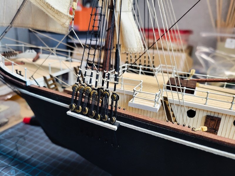
Thanks Hake, that's perfect. ------------------------------------------------------------------------------- Hi everyone, thanks for coming in. I have a nice big update lined up so I'll get right into it. After seeing the pic Hake posted I went ahead and belayed the jib sails. The ropes were everywhere and I couldn't picture a way forward with all that in the way. The port side is the display side so the starboard sheets were drawn taught and belayed on the pin rails. The port side were left slack and belayed. My approach for the fore mast is to work from the inside out, or least accessible points first. Since I'm following Hake's rigging plan, not OcCre's, that meant the staysail halyard and the gaff throat halyard would be the hardest to belay at the bottom of the mast. The points are between the mast and the deck house. I can't explain the patience that was required in trying to get these two done. I lost track of time after fighting with it for about an hour. I didn't help anything by belaying the jib sail's sheets, which can be seen in the pic above. In the end though it's done, and the remaining points won't cause an issue. Detail of the staysail halyard and gaff throat halyard. The fore sail was also attached to the yard, and then attached to the main mast. I forgot to take a pic of that though. A detail to note is I opted to reverse the robbands from port to starboard instead of sewing it on continuously. The gaff peak halyard is installed and belayed. If you look extra close at the block attached to the mast, it's not connected on one side. Once again the thin CA I used a while ago made these blocks hard as a rock. I try to massage it back and forth it try and break it up a bit and the thread ends up breaking. Luckily it remains glued to the mast, so I can re-glue it and it's fine. For my future builds I won't be using thin CA on those blocks, but fray check instead. I switched to that on about half of the blocks and it works perfectly. When belaying the peak halyard I held up the gaff sail to ensure the angle is correct. Now is about the time to discuss the elephant in the room which is installing said gaff sail. As I belayed 3 of the 11 ropes to the fore mast I was hit with a realization that the gaff sail is going to pose a problem. I really should have got it installed before all of this because trying to insert the main rings is going to be an absolute chore. I'm at a standstill right now until the sail is complete and installed because I don't want anything else in the way. I ran out of tan line and will need to make more, so I focused on the lifts. These are run through the mast top but not belayed, so there isn't any tension and they look pretty loose. Another reminder to future me that those mast blocks were frozen solid, so more evidence not to thin CA those. From this angle you can also see I moved the staysail halyard block closer towards the mast so it can belay through the lubber hole. The lifts and clew lines are run through the mast top, but not belayed. Next steps are to make more tan rope so I can prepare the fore gaff sail with a bolt rope and corners. I know I can bend the rings enough to get them off the main mast so I believe I'll install them on the sail, sew on the robbands to the gaff, then bend the main rings on to the mast one at a time. Once that's on everything else can be belayed. Thanks for checking in!
-
Thanks Keith. I was concerned if I belay the guys to the railing (or rather now, the cap rail behind the kennels) I wouldn't have room for the main gaffsail. It'd be pressed up right against the guy lines. I think I've decided to show the fore and main gaffsails exactly how occre has them, slightly furled against the mast. This way the gaffsail won't be in the way of the main funnel.
-
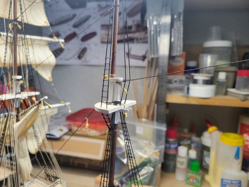
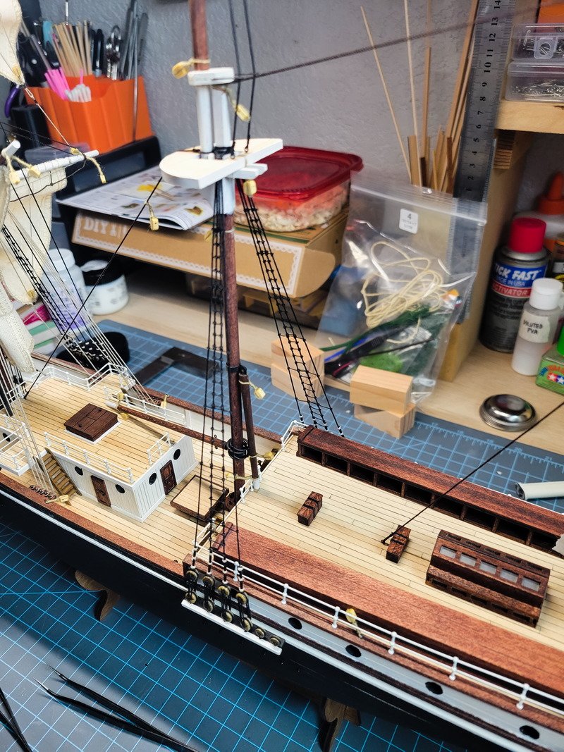
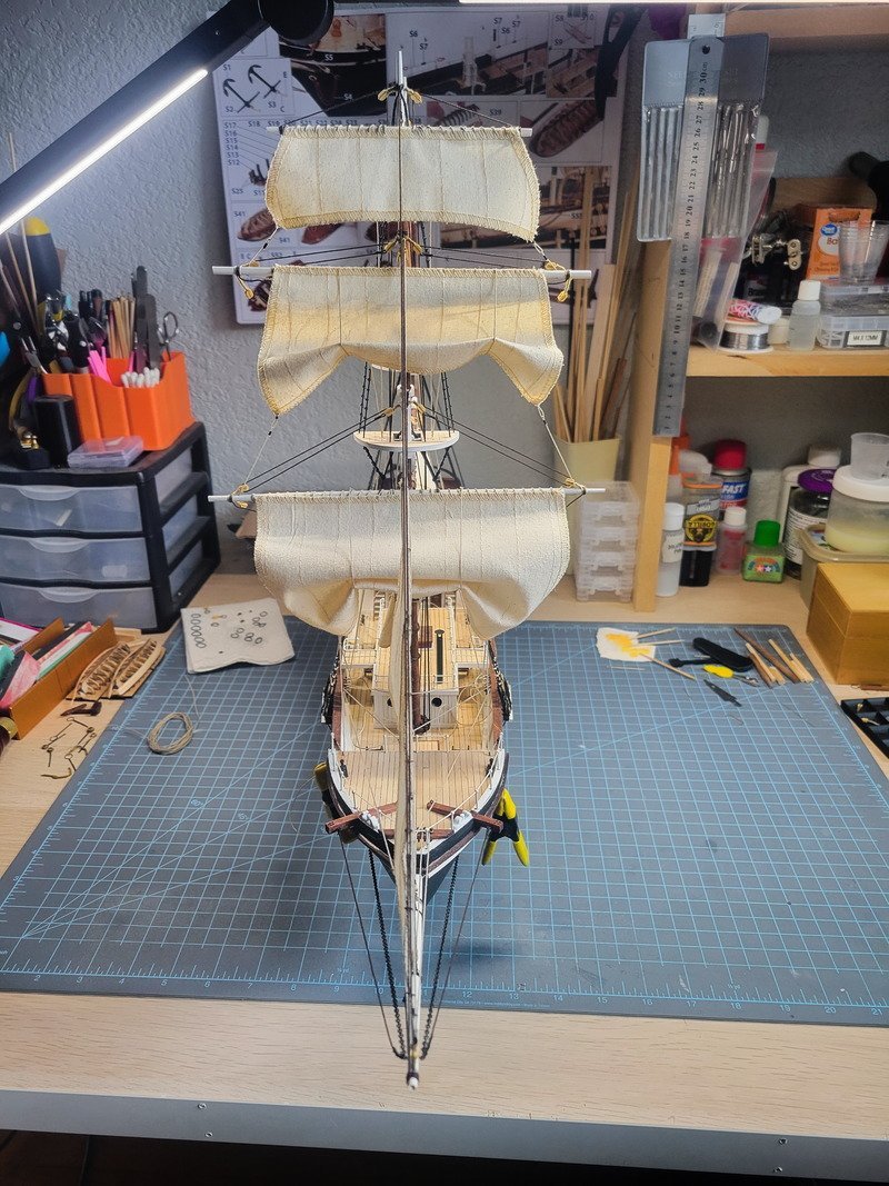
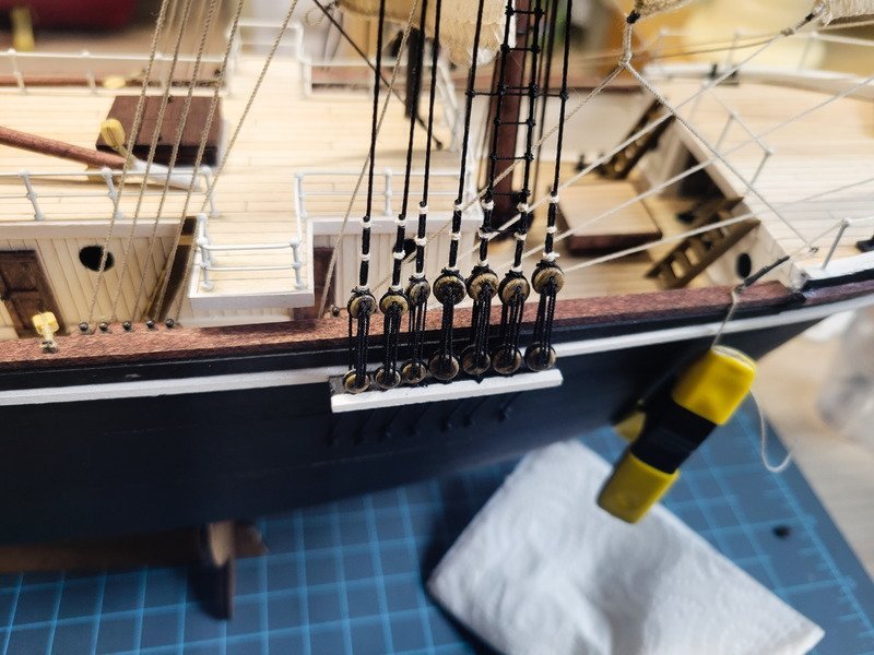
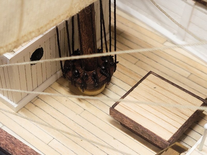
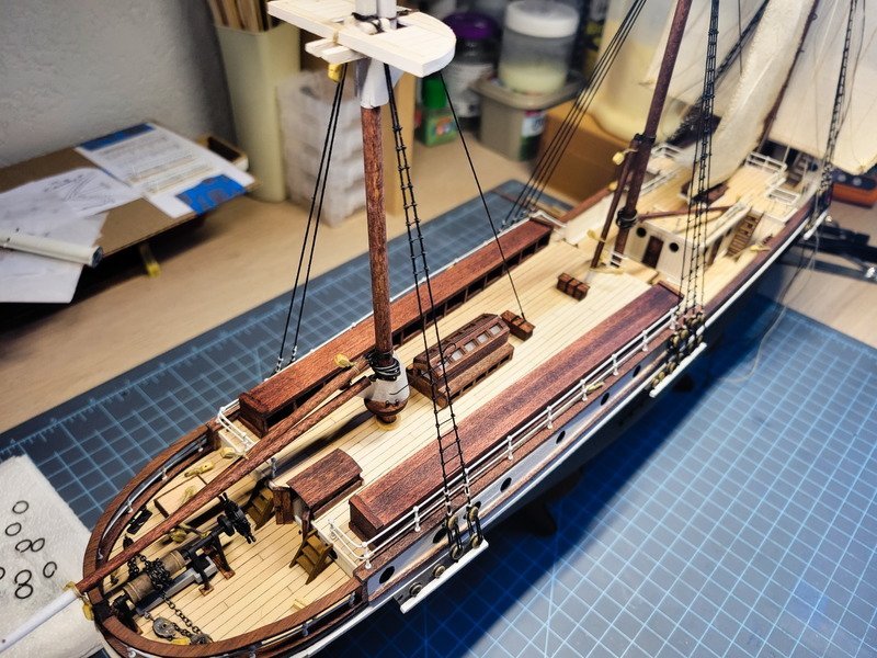
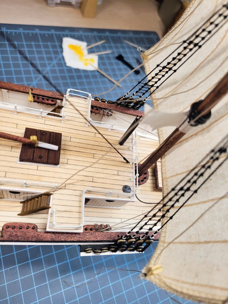
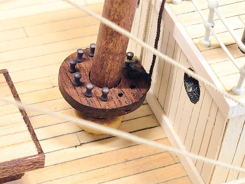
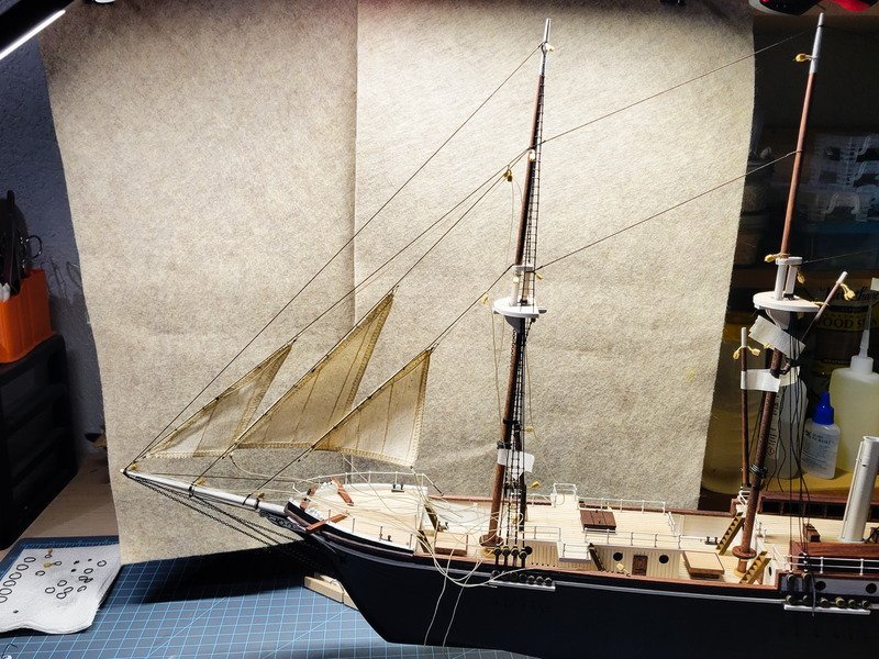
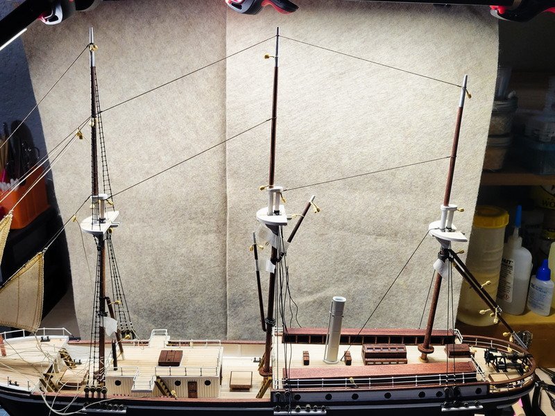
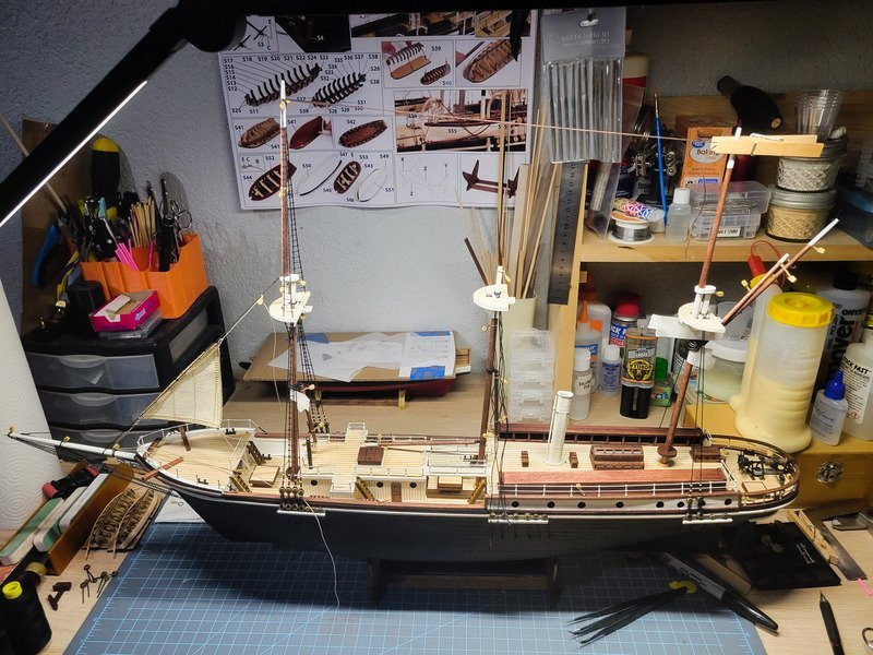
Hi folks! My last post I mentioned finishing the main mast belay pin rack at some point in the future. I fully intended not to work on it today, but it ended up finished and installed. Like the others I installed some cheeks and glued everything in. I got very lucky that I didn't sand it into a perfect circle because I didn't account for the upper trim on the mizzen deck, and it almost didn't fit. The pin racks are definitely out of scale, and the main mast rack ended up higher than I thought it would. But it looks cool, so there's that. As the glue for the main mast dried I got two pairs of shrouds in. I didn't photo it, and I'm very happy with how the masts are straight up and down when viewed port to starboard...however the main mast top isn't quite level. I'm annotating it here as a reminder to make doubly sure it's correct next time. In fact, I have a jig in mind and will be using it for the next one. Next I finished up and rigged the flying jib and jibsail exactly like the staysail in a previous post. This allowed me to run a single rope for the remaining three stays on the bowsprit, threading on the sails and blocks as I went along. I don't have anything belayed yet and I'm not sure if the sails are in the correct position. I need to search out some reference of her with her sails out, so if anyone has any please feel free to share! I can always adjust them into a more correct position. Since installing those fore stays there was enough pressure on the foremast to warrant installing the remaining stays between the masts. I'm missing the main mast top to quarter deck house, but otherwise the rest are complete. One thing mulling around in the back of my mind is rigging the main funnel. In London It's shown to be belayed to eyebolts on the deck. But then in the ice it appears it's belayed to ... the railings? I'm really not sure. I'm curious where to go for that. I could easily belay to the railings at any time, but if I attach to eyebolts on the deck I'll need to install those sooner rather than later. I appreciate anyone's opinion on that! Thanks for stopping by!
-
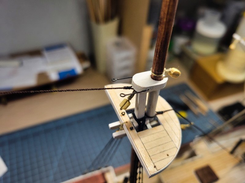
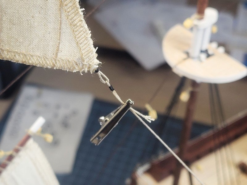
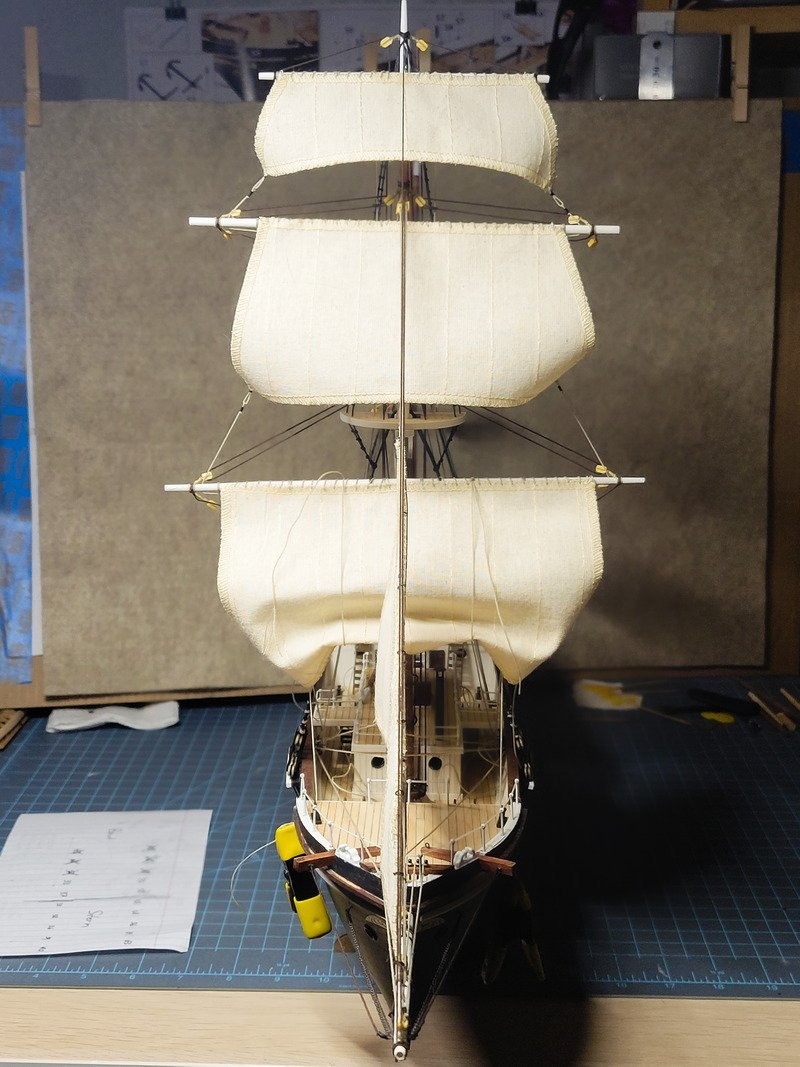
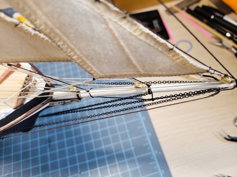
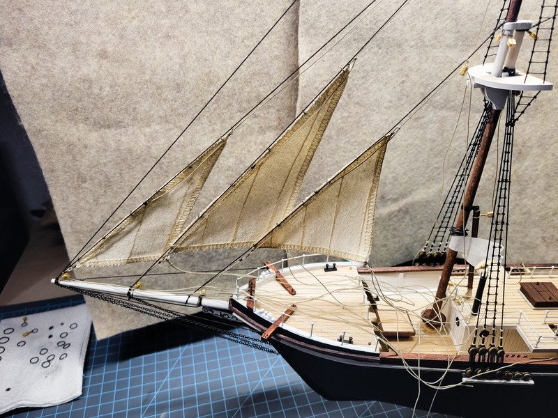
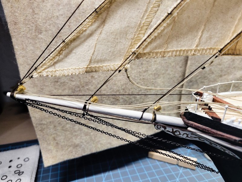
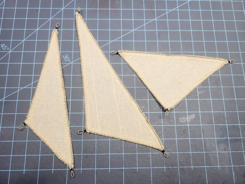
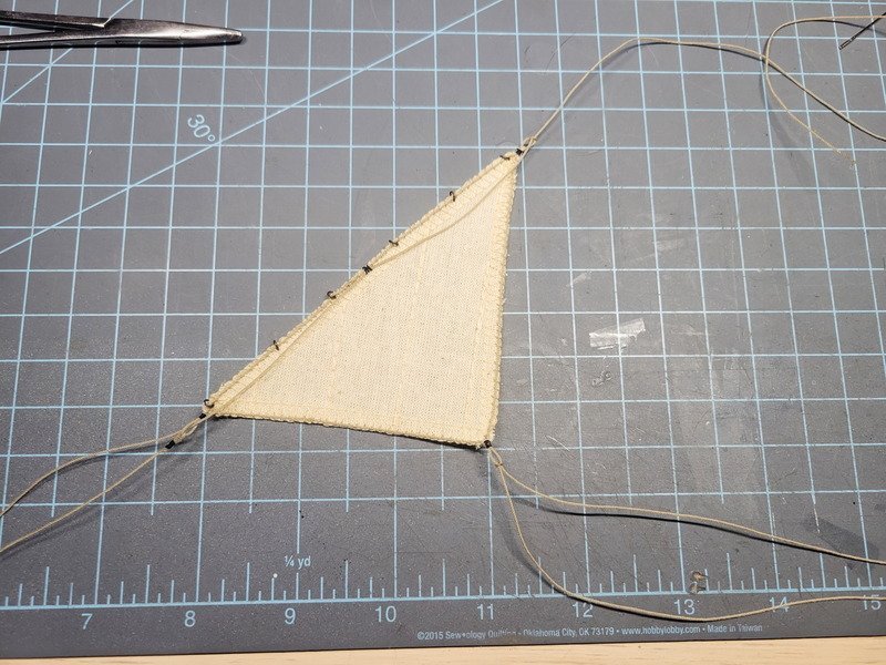
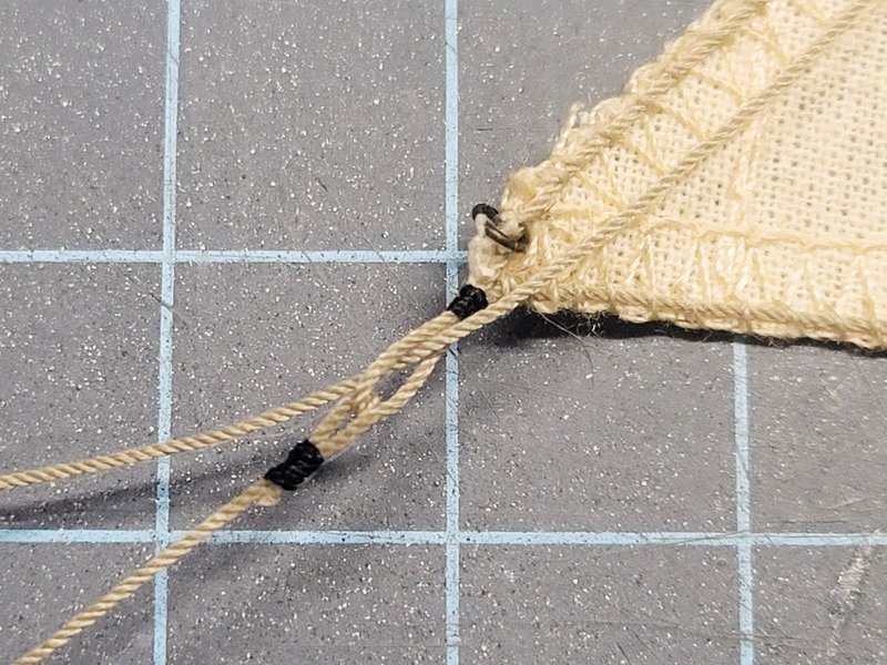
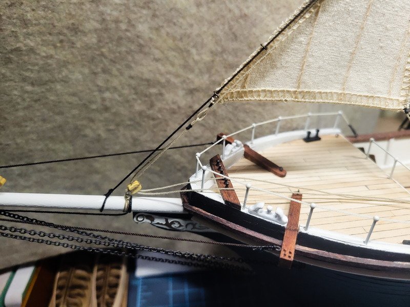
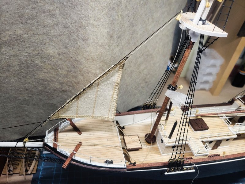
Hi everyone, thanks for the likes and comments! I spent a good amount of time today making the rest of the rope needed for the rest of the rigging. Taking a break from ratlines, I decided to finish up the bolt ropes for the flying jib, jibsail, and staysail. Something to note about the sails included with this kit. There's a finished side, and a rougher not-so-finshed side. When installed the finished side of the flying jib and jibsail face port, but the staysail's finished side is starboard. I caught this once I was 3/4 of the way done with the staysail, and won't be ripping it out. This means the bolt rope is installed on the port side of the staysail, but it's installed on the starboard side for the flying jib and jibsail. A minor annoyance for sure, but hopefully won't be the most noticeable thing. I'm skipping around the rigging order here but went ahead and fastened the foremast forestay, but left the bowsprit side loose. This way I could just slide the stay through the rings of the staysail. The staysail was completely rigged before installing on the forestay. Then the bowsprit side was fastened, and the staysail halyard, downhaul and tackline were run through their blocks. I'm not belaying them yet so I can move the ropes around if need be to install other things. One thing to note for future me reading this: I used thin CA on the blocks I put on the bowsprit many months ago. They're locked in place, including their angles, and when I tried to move around the block for the downhaul and tackline it broke and needed to be re-glued. The forestay is also not necessarily in the correct position on the bowsprit, and it's not realistically attached. There needs to be a cleat under it, or it should be snug against the block. Since the block doesn't really move, the downhaul and tackline would've looked odd and kinked running through the block and to the pin rack. And an overall shot. I attached a temporary stay between the fore and mizzen top masts. I'll probably trade off doing ratlines and rigging the flying jib and jibsail. Eventually the main mast pin rack will be finished and I'll get the lanyards and ratlines in. Thanks for reading along!
-
Looking great Tom, and I really like your additions as well. I'm very keen to see what you come up with in regards to the anchors. I've painted mine and attempted to rig one of them, but indeed all of the pictures I've seen show they weren't rigged at all. I ended up removing it to ponder on another day.
- 206 replies
-
- 1
-
-
- Endurance
- Shackleton
- (and 2 more)
-
The way Occre chose to build this model is peculiar. In that same vein, since the telegraph wasn't there during her time in London, neither would be the dog kennels. So I'm not choosing one definitive configuration over another, just what looks good.