Tomculb
-
Posts
318 -
Joined
-
Last visited
4 Followers


About Tomculb

Recent Profile Visitors
2,179 profile views


-
 Canute reacted to a post in a topic:
HMS Endurance by GiddyGibberish - OcCre - 1:70
Canute reacted to a post in a topic:
HMS Endurance by GiddyGibberish - OcCre - 1:70
-
Knocklouder reacted to a post in a topic:
Endurance by Tomculb - OcCre - 1:70
-
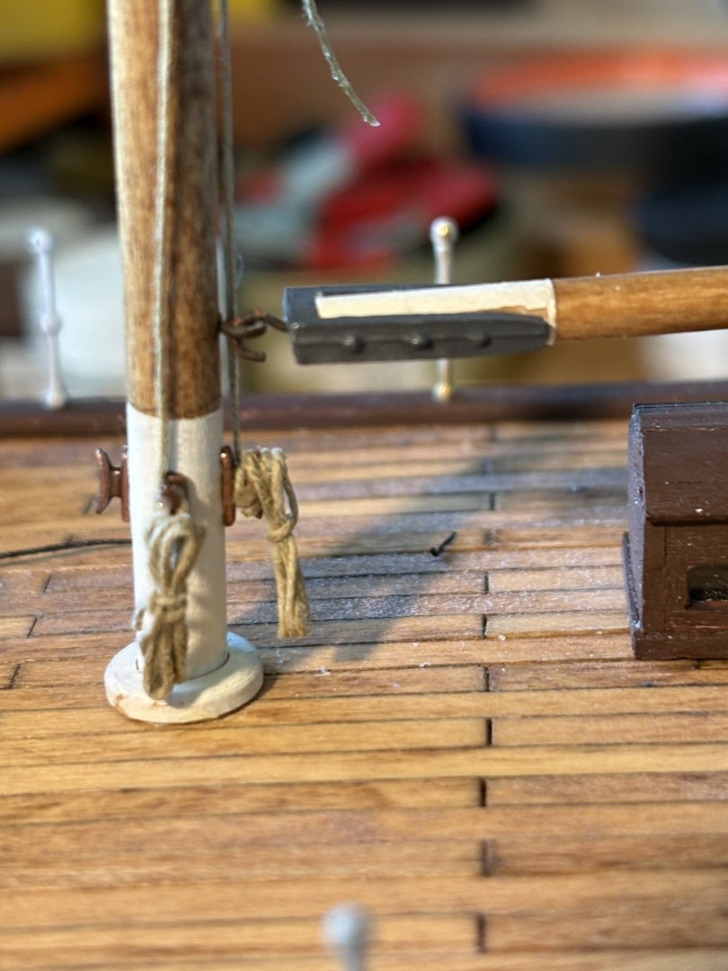
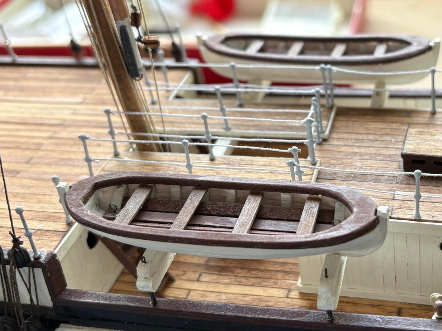
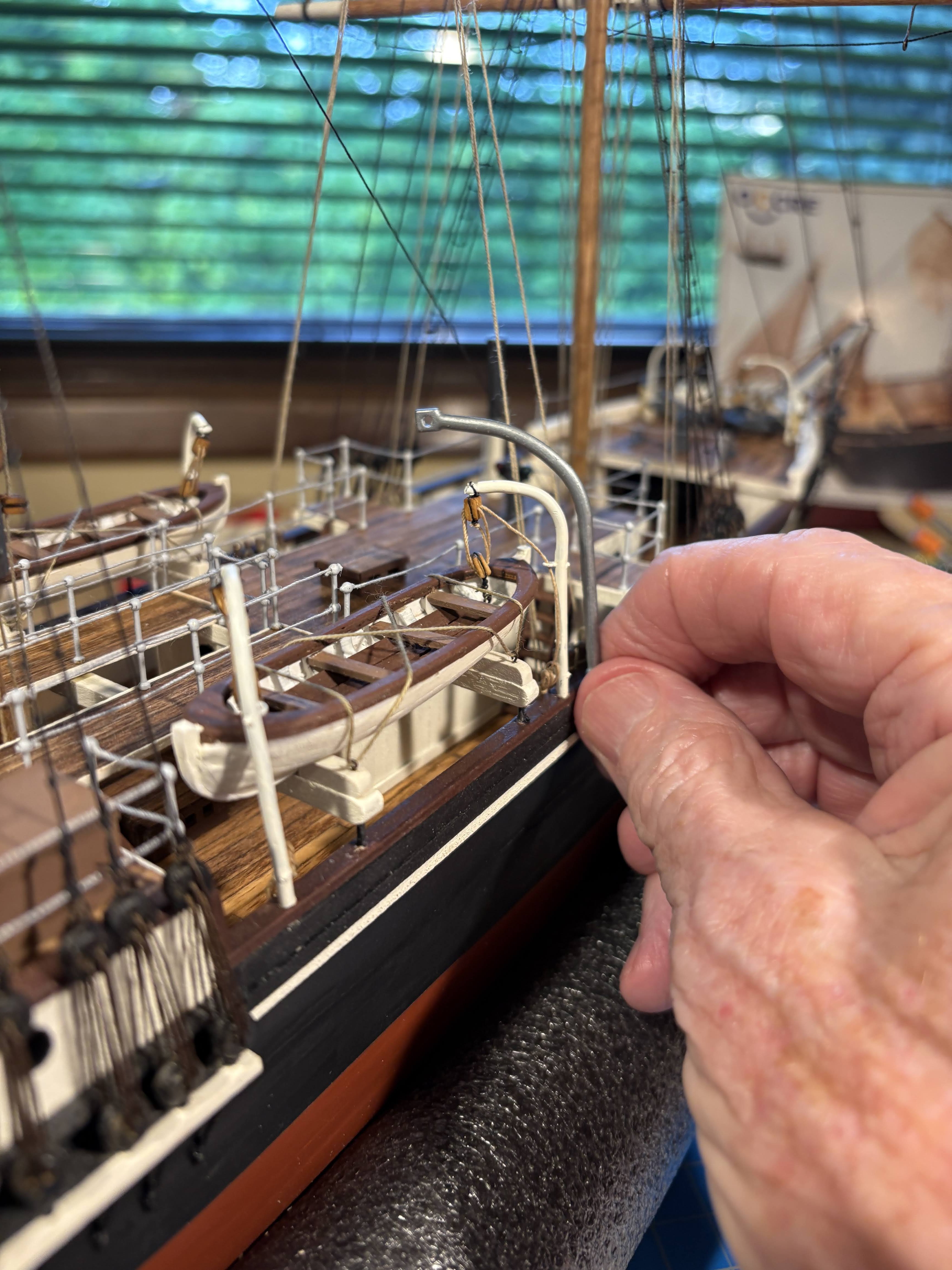
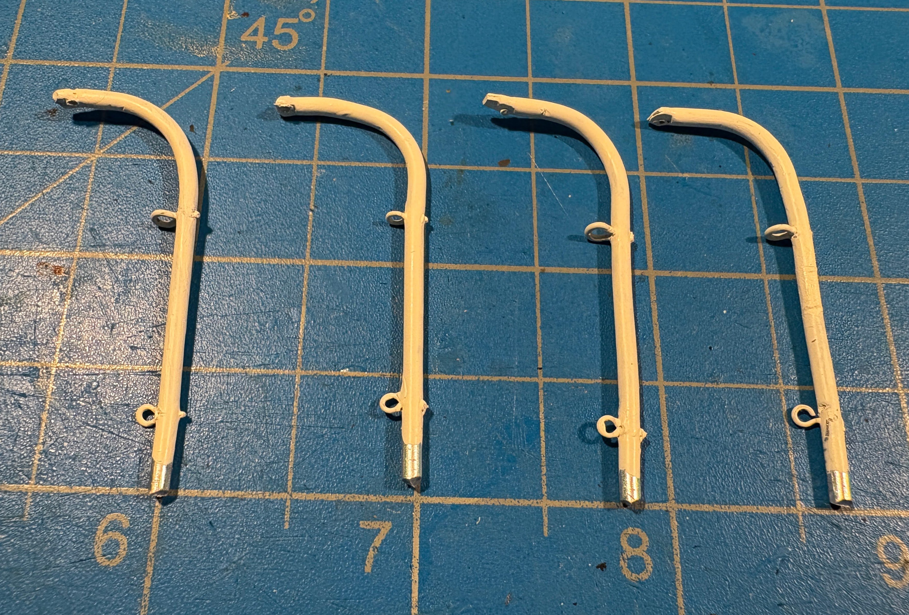
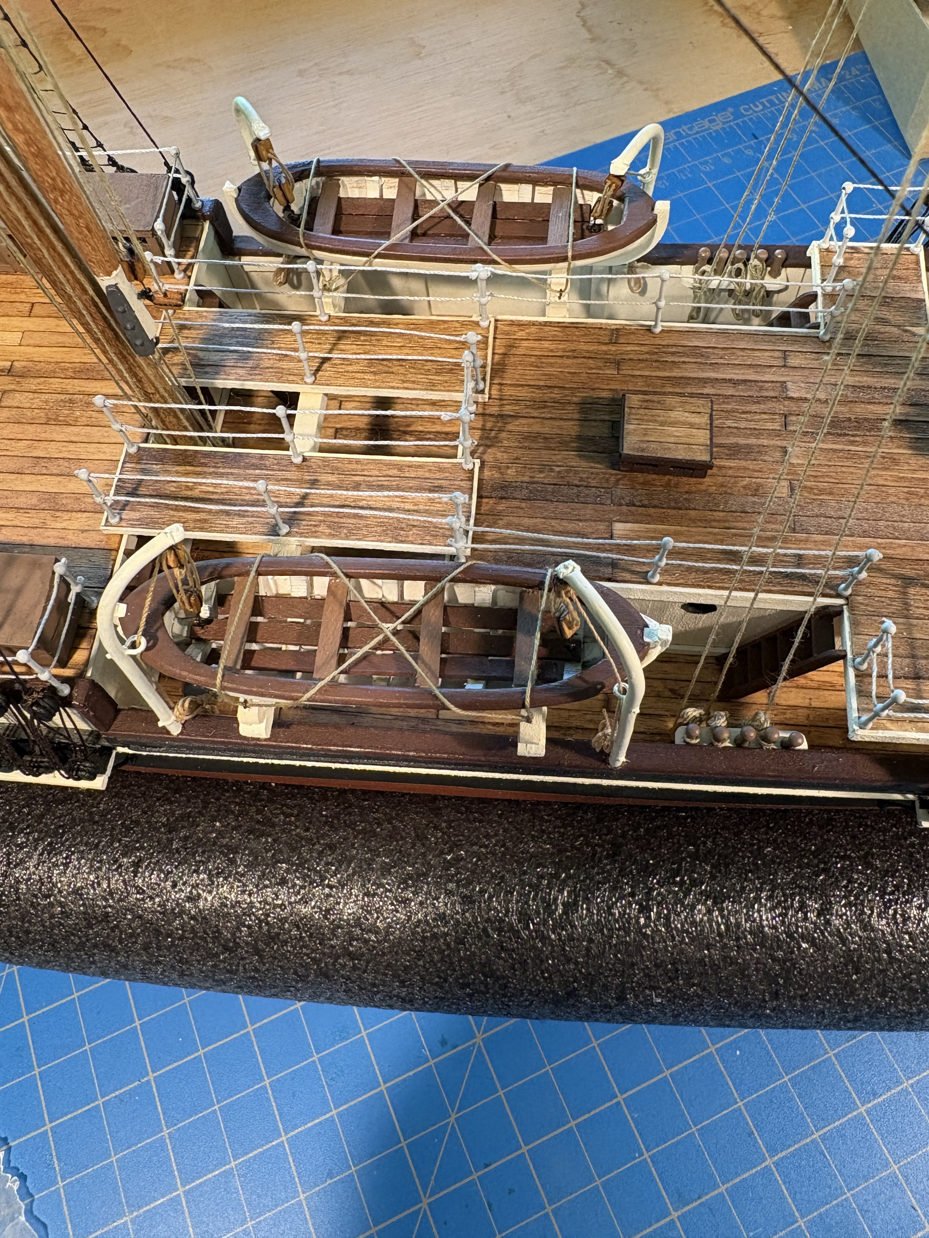
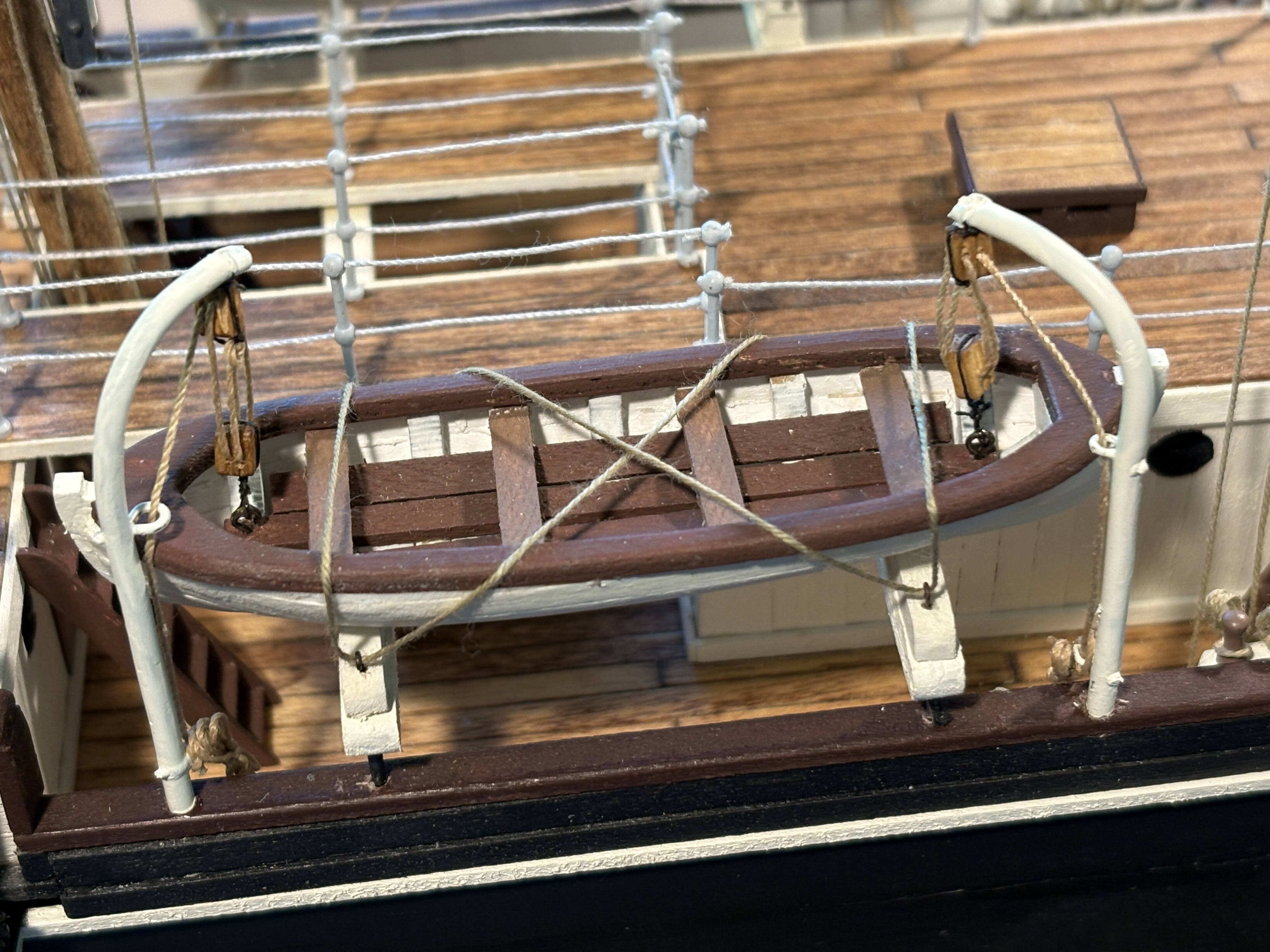
 A year ago March I made anchor davits from some 1mm aluminum wire that I had lying around. It was very easy to bend and otherwise work with, and I had no idea where it came from. Some Google sleuthing revealed that it’s often used in crafts, which led to the realization that this wire was probably something our daughter played with probably more than 25 years ago. That wire was too thin to work for these davits, but I found some 2mm wire online that worked just fine. At least for these two boats, the davits supplied by OcCre not only don’t work facing inboard, but IMHO they are too large for this scale. Bending this wire to the desired shape was quite easy. I found a highlighting pen that made a perfect jig. I then used some blunt nosed pliers to flatten the upper end of each wire and put a hole in each one to attach the tackle to. The latter proved to be far more difficult than I expected; in part because my mini drill bit set is not very good quality, and in part because flattening the ends probably made the aluminum harder and denser. The problem I had was creating enough of an indentation so that the drill bit didn’t dance all over the place before finally digging into the aluminum. What finally worked was driving a tiny nail through the metal, and enlarging the hole with an appropriately sized bit. Then I realized that the tackle couldn’t travel in a straight line to a cleat positioned where any crew member could reach it; it would drape against the side of the boat, which just didn’t look right. So I drilled holes for small eyebolts for the line to pass through. I don’t have, and probably couldn’t reliably handle, blocks small enough to fit the bill. Next challenge was making cleats for securing the end of the tackle, very much like the wire cleats I attached near the bottom of each mast. The masts of course are significantly larger in diameter than these davits, and they provided a much better gluing target than these davits. After an hour or two of unsuccessful efforts, I gave up and decided another eyebolt would have to serve as a faux cleat. Next step was to give the assembled davits a bath in denatured alcohol to get any finger grease off of them (I kind of guessed that was a good idea), then painted them with the same Model Shipways “Warm White” paint that I used on everything else that is white on the ship. Rigging the tackles was pretty straight forward. As with the anchor tackles, I used photo-etched hooks (left over from my prior build) to attach the tackles to the eyebolts previously installed in each boat. Those hooks are all but invisible in the photos below. Tying off the running end of each tackle was pretty straightforward as well. Far more challenging was hanging a rope coil on each eyebolt rather than on a cleat; it took quite a bit of effort for something that is almost not visible. A dab of white paint on the top of each davit hides the thread used to tie the upper blocks to the davits.


- 183 replies
-
- 1
-
-
- Endurance
- Shackleton
- (and 1 more)
-
Tomculb reacted to a post in a topic:
New BlueJacket Shipcrafters kit in development: West Coast lumber schooner
-
 Tomculb reacted to a post in a topic:
HMS Grecian 1812 by ECK - Vanguard Models - 1:64
Tomculb reacted to a post in a topic:
HMS Grecian 1812 by ECK - Vanguard Models - 1:64
-
You are doing a superb job on Grecian, and I'm going to start following your build closely. My kit arrived a couple of weeks ago, but it will be some time before I get started on it. I need to finish Shackleton's Endurance, and I also have the NRG's half hull project waiting. One question I have . . . since you have painted and copper plated the hull, what purpose did your second planking serve? I asked the same question of others who were working on Endurance, didn't get a convincing response, and decided to forgo the second planking. The first planking required a lot of filling and sanding (you did a good job of that on yours), but I was as happy with the painted result as I would have been had I done a second layer of planks. Maybe I'm just lazy . . .
-
Tomculb reacted to a post in a topic:
HMS Grecian 1812 by ECK - Vanguard Models - 1:64
-
eatcrow2 reacted to a post in a topic:
Endurance by Tomculb - OcCre - 1:70
-
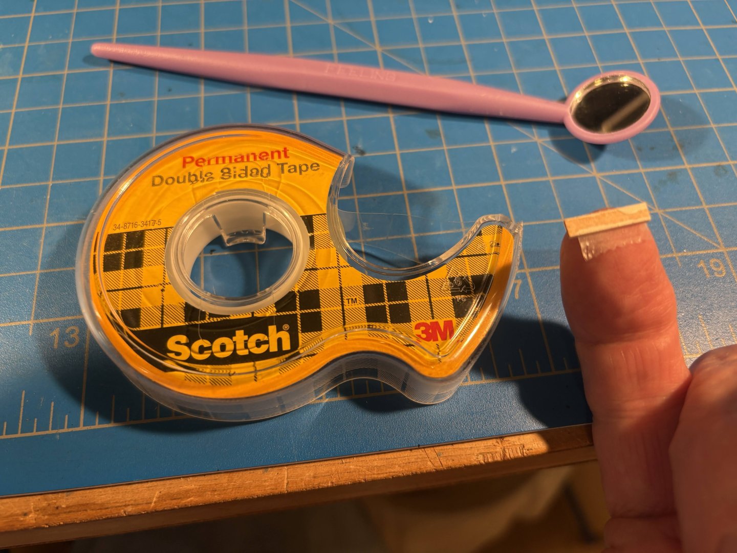
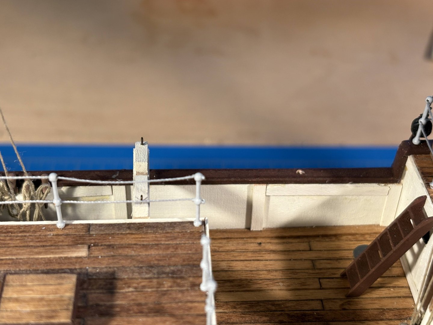
Briefly following up on the personal note that started my last update, the depth of field problems disappeared within a day or two of posting that comment. I had cataract surgery on the other eye yesterday afternoon, probably won’t be doing anything on my model today, but expect that today’s issues will gradually disappear as well. 😄 I thought this post was going to be about davits for the ship’s boats, but there were several things that needed to be done before tackling that job. A couple of the many Endurance photos available online show the forward pair of davits to be significantly different from the rear ones. The forward ones are mounted within the bulwarks, while the aft ones are attached to the outside of the hull, similar to what OcCre would have you do with both pairs of davits. I ordered some 2mm diameter aluminum wire to make the davits (more on this in my next post, about the davits). The bulwarks are made from 2mm thick plywood; an obvious problem. I decided that the best solution to that problem was to glue a couple of 2mm (or perhaps 1/16”?) thick strips on the inside of each bulwark, just below the rail cap. Much easier said than done in the narrow space available, especially for the forward strips. Fortunately the beam holding the aft end of the boats was only dry fit, and I was able to remove it, making a little more room available. After trying too many unsuccessful methods to talk about, what worked was applying a small piece of double sided scotch tape to a finger to which I stuck a strip, applying a bit of glue to the exposed side of the strip, and pressing it blindly into place. For some reason I had a dentist’s mirror (plastic: probably a toy) where I store tools I never use, and I used that to view and make necessary adjustments. All of this so there would be enough wood available in which to drill holes for the davits. Before I could install the davits, I needed to glue the boats in place, and before that I needed to rig the lines which lash the boats in place, and before that I needed to glue the planks which run between the deck house and the deck behind it, and before I did any of that, I needed to glue the aforementioned beam in place. And of course I needed to fabricate the davits, but that will be the subject of my next post. My fingers are too big and clumsy to rig the boat lashings with the boats in place, so I did the rigging very loosely, leading the threads through the previously installed eyebolts in the appropriate order, then sliding the boats though the loose loops of thread and into place after carefully placing a dab of glue where each boat’s keel will rest atop the beams. After the glue dried, I tightened the thread and somehow tied off the end of each thread with a half hitch. Both ends of the thread were knotted to the same eyebolt, on the inside rather than the outboard side of the boat, so as to hide the unsightly knots. I also found some time to rig a few ratlines.

- 183 replies
-
- 1
-
-
- Endurance
- Shackleton
- (and 1 more)
-
Tomculb reacted to a post in a topic:
Endurance by Tomculb - OcCre - 1:70
-
The Gimps Chimp reacted to a post in a topic:
Endurance by Tomculb - OcCre - 1:70
-
Tomculb reacted to a post in a topic:
HMS Endurance by GiddyGibberish - OcCre - 1:70
-
Tomculb reacted to a post in a topic:
HMS Endurance by GiddyGibberish - OcCre - 1:70
-
clearway reacted to a post in a topic:
Endurance by Tomculb - OcCre - 1:70
-
clearway reacted to a post in a topic:
Endurance by Tomculb - OcCre - 1:70
-
Tomculb reacted to a post in a topic:
NRG half-hull planking project by CPDDET - 18th century merchant ship
-
François de Saint Nazaire reacted to a post in a topic:
Endurance by Tomculb - OcCre - 1:70
-
Snug Harbor Johnny reacted to a post in a topic:
Endurance by Tomculb - OcCre - 1:70
-
Knocklouder reacted to a post in a topic:
Endurance by Tomculb - OcCre - 1:70
-
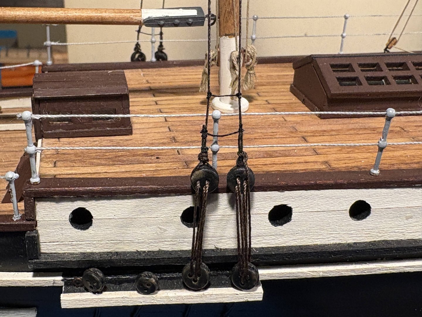
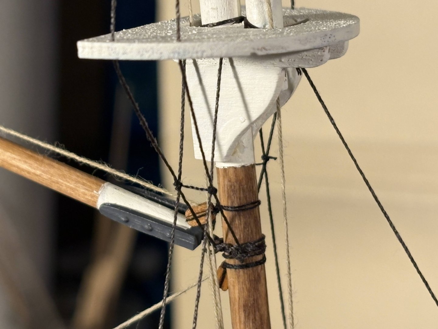
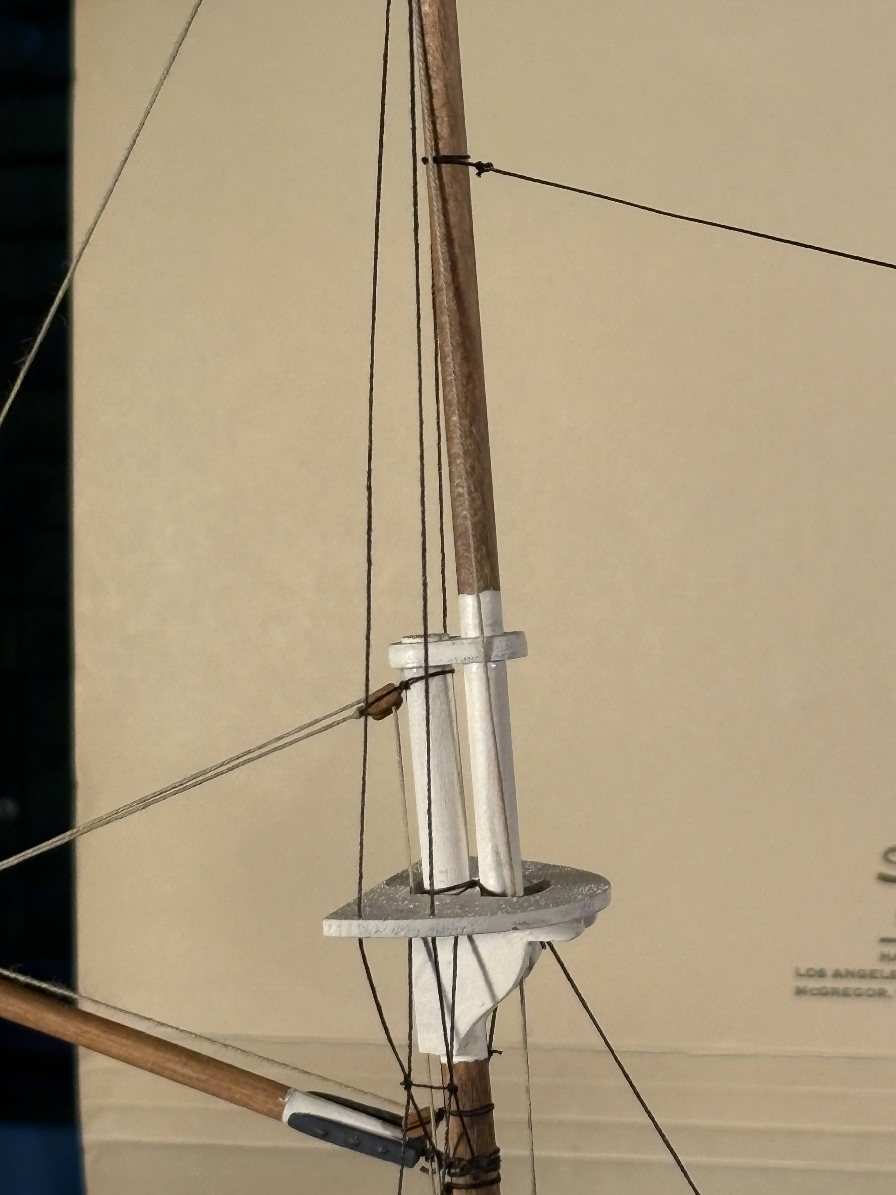
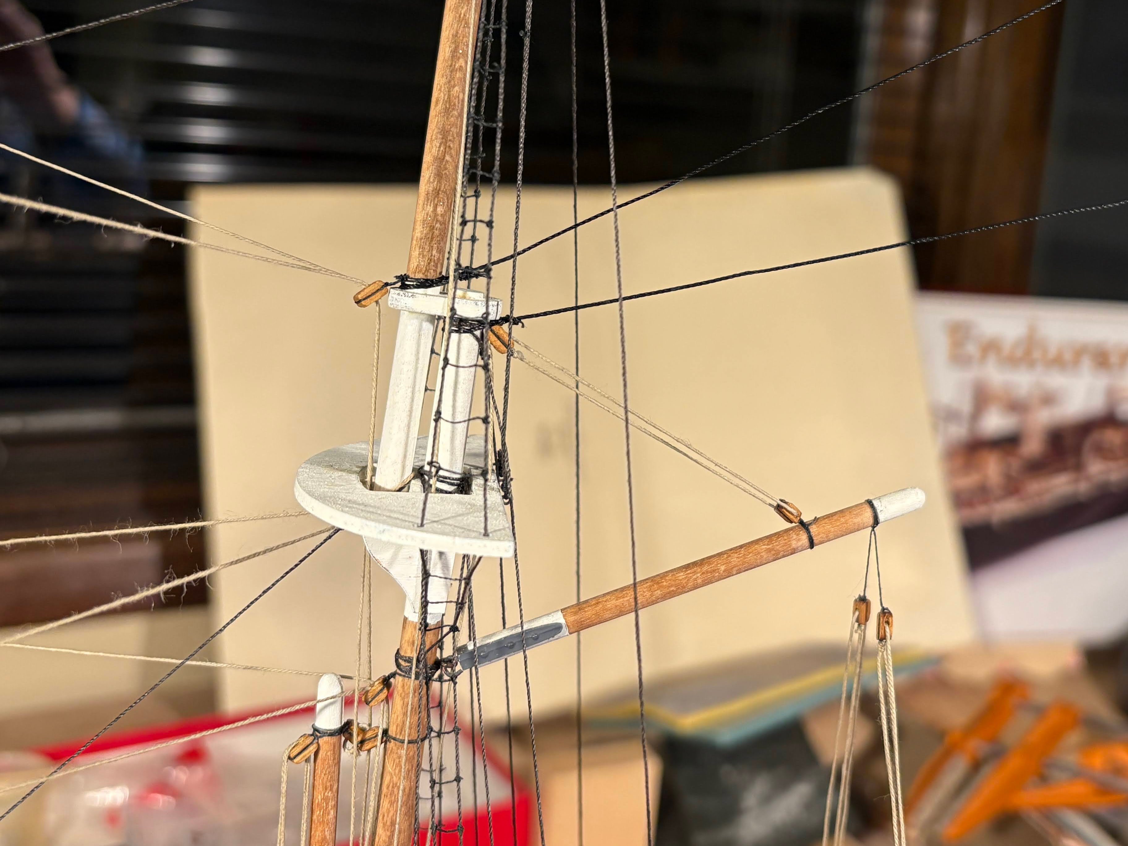
My next accomplishment was the mizzen mast shrouds. My biggest challenge here was that I had cataract surgery this past Monday on my left eye (the one that I use for distance vision), and my right eye surgery is still two weeks away. It still has a contact lens, for reading distances. For some reason the combination threw off my depth perception (with contacts in both eyes, that never seemed to be a problem). Several times using tweezers to grab the end of a piece of thread, I found myself grabbing thin air half an inch or more away from the target thread. I have a post-op appointment with the ophthalmologist this coming week and I’ll ask him about this. Other than this one issue, everything has gone very well surgery-wise. First I rigged the two lower shrouds which will hold the ratlines. The other lower shrouds will be installed only after the ratlines have been completed. Then I rigged the two upper shrouds. Since things are getting a bit crowded at the top of the mast, with more shrouds still to be secured up there, I decided to run these shrouds through a hole in the mast. Trying to hold the mast steady while drilling was a bit challenging, and in the process of not doing that well, I broke loose the upper two stays running between the mizzen and main masts. That proved to be a bit of a blessing in disguise, as I had used some thread that was a little bit thicker than the tread I used for all the other stays. Barely noticeable, but it bugged me, and this time around I used the right size of thread. Rigging ratlines is pretty tedious, and I decided I would do two or three on each side at a time, in between working on other, unrelated, projects on the model. So far I have done two ratlines at the bottom of the lower shrouds just above the deadeyes, and I have done the most challenging ratlines, the ones that tie the lower shrouds to the futtock shrouds, just under the top. It was here that I had the most problems with depth perception. OcCre has you install ratlines on the upper shrouds as well, but as others have pointed out in their logs, the Hurley photos show the upper shrouds without ratlines. Much as I wanted to tie more ratlines [sic], my Endurance won’t have any ratlines up there. I’m beginning to see a small glow in the darkness; could that be the proverbial light at the end of the tunnel??

- 183 replies
-
- 5
-
-
- Endurance
- Shackleton
- (and 1 more)
-
Thanks Mark. If you look at the first page of my log, you'll know more about how I planked the deck than I remember. I do remember that it was darker and perhaps a little redder than I wanted. Fortunately I think it's aged well, but maybe I've just gotten used to it. I toyed with the idea of staining each strip of wood separately before cutting them to plank length, with the idea of having some plank specific variation, but at the time I decided was too much work. I'm thinking I'll do that on my next build. I do think that OcCre's planking is way too light in color, but maybe that's just my personal preference.
-
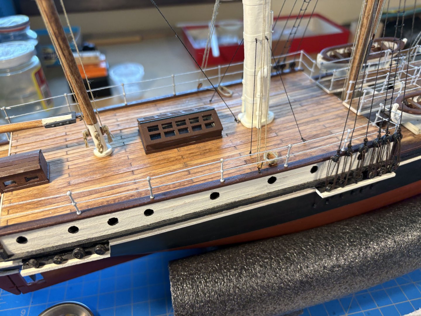
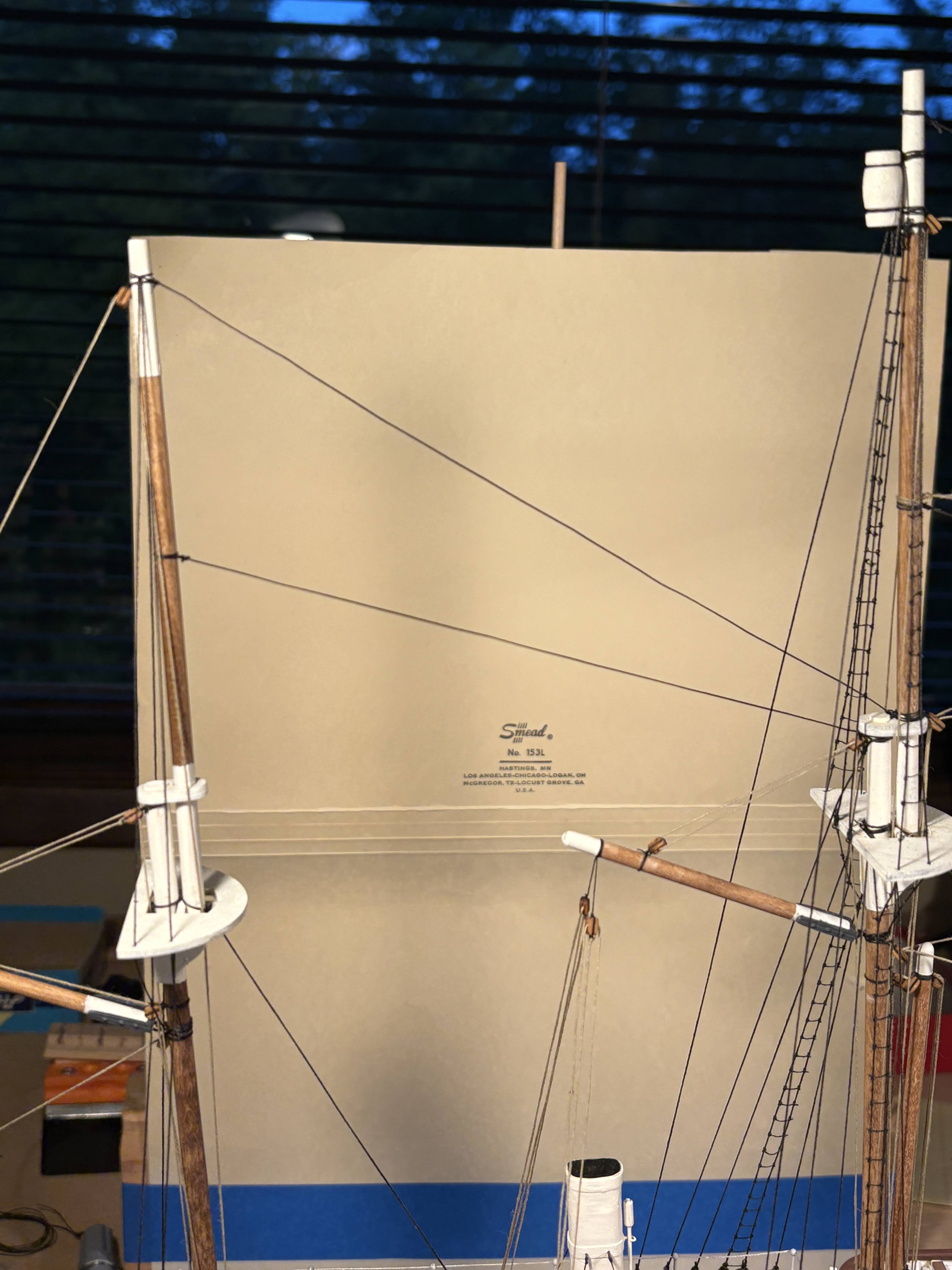
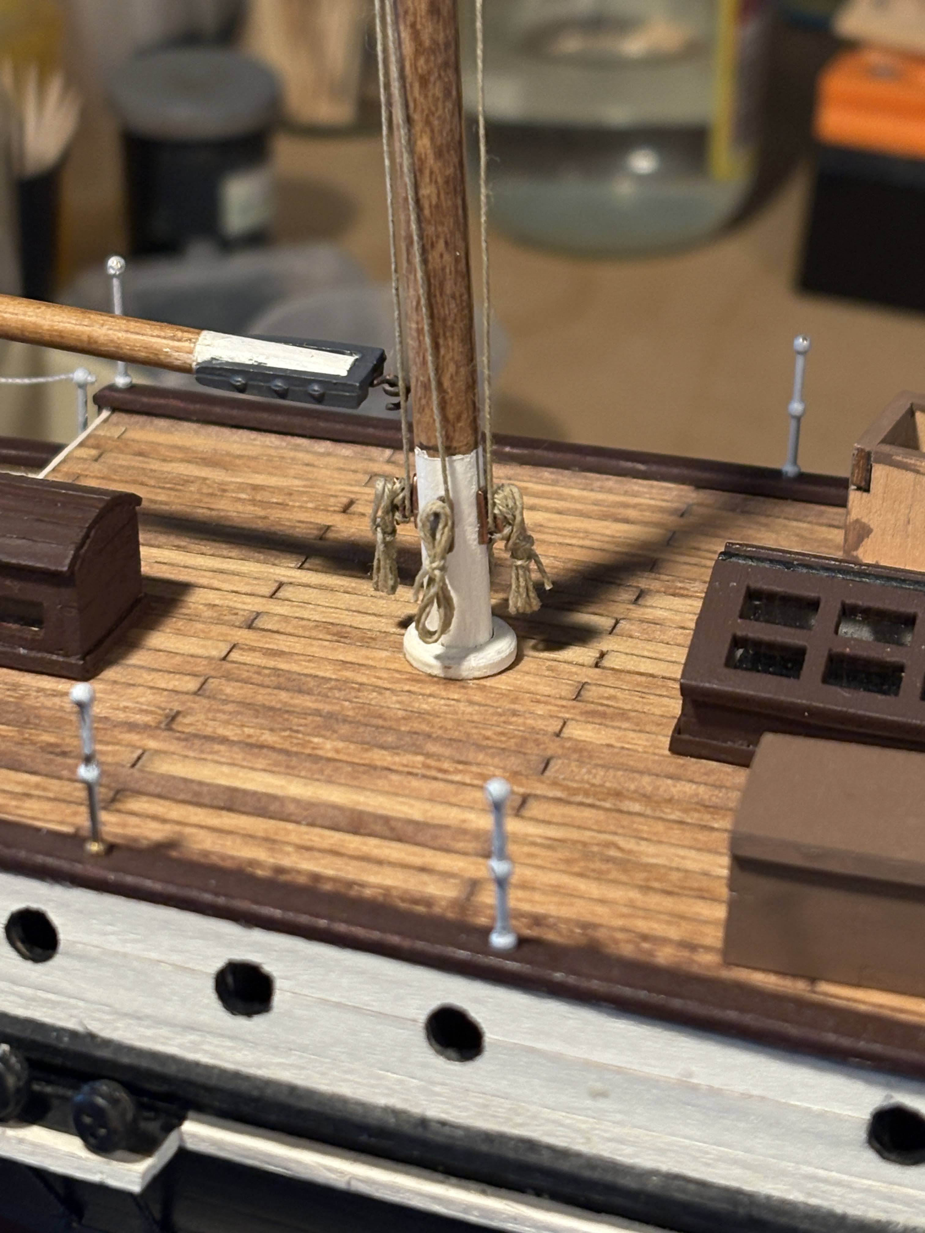
Progress on several fronts . . . Blocks and cleats for the gaff and boom sheets were installed on deck and rigged, and rope coils were then glued on top of the cleats. The previously described halyard and outhaul for the mizzen topsail have been run down to, and secured to, cleats at the base of the mizzen mast. The three stays running between the mizzenmast and the main mast have been installed. OcCre has you install the upper two of these stays running upward as you move forward, not downward as all the other stays run between the masts. The Frank Hurley photos I looked at shows them running downward; that is, they are fixed at a higher position on the mizzen mast than on the main mast. I chose to rig them as Hurley’s photos show. Stanchions and railings have been completed. Threading the rails behind the main mast shrouds was a challenge; the rest went pretty easy.


- 183 replies
-
- 3
-
-
- Endurance
- Shackleton
- (and 1 more)
-
Tomculb reacted to a post in a topic:
Endurance by Tomculb - OcCre - 1:70
-
Thanks Phil for setting me straight. As I look at OcCre's photo of the finished model, I see that the two gaff sails rigged without booms are furled in the way you describe. So perhaps I was correct months ago when I questioned why OcCre rigs those gaffs with throat halyards when the goosenecks for those gaffs were fixed to the mast. The two models I have done of smaller vessels (America and Joshua Slocum's Spray) have gaffs with jaws and parrals. My Niagara model, on the other hand, has only one gaff rigged sail, on the mizzen, and its gaff has jaws and a parral, so it can be lowered to the boom. Thanks again for your insight.
- 183 replies
-
- 1
-
-
- Endurance
- Shackleton
- (and 1 more)
-
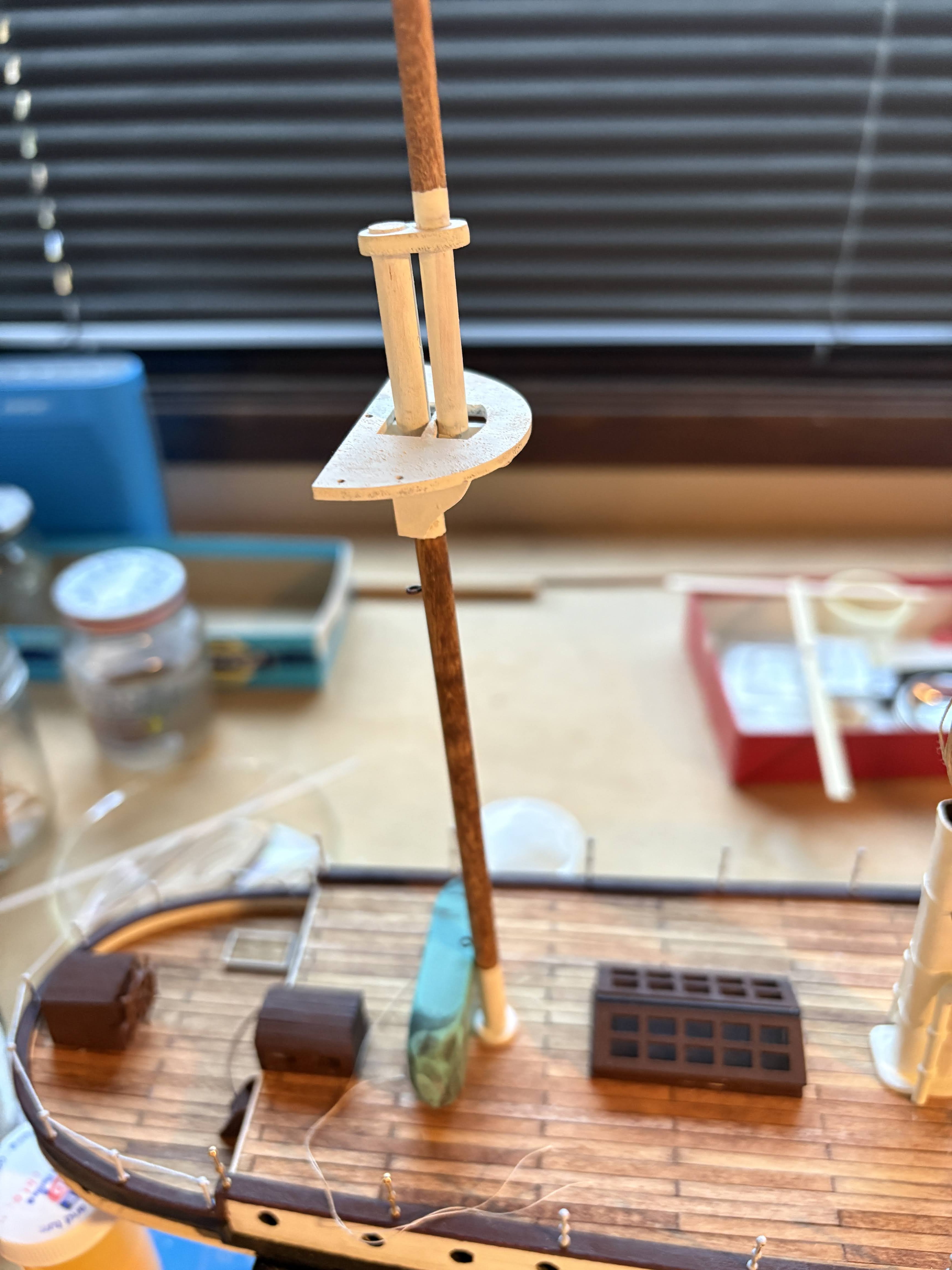
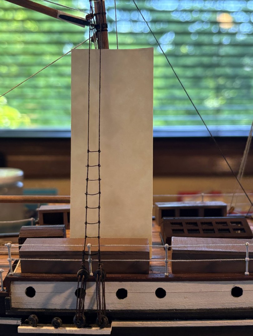
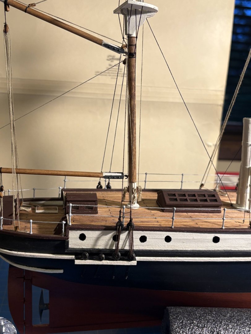
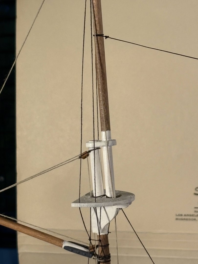
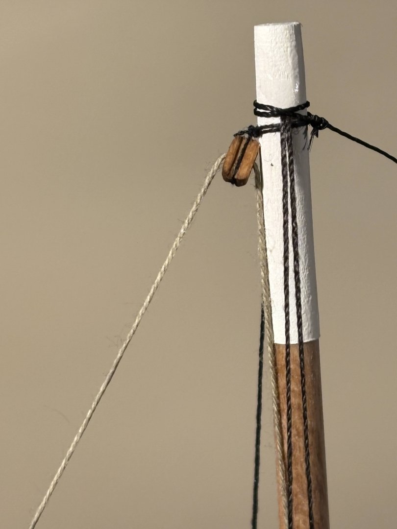
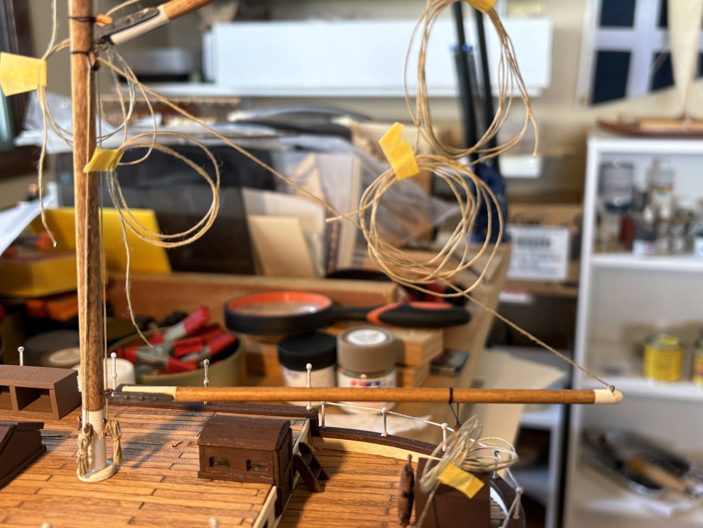
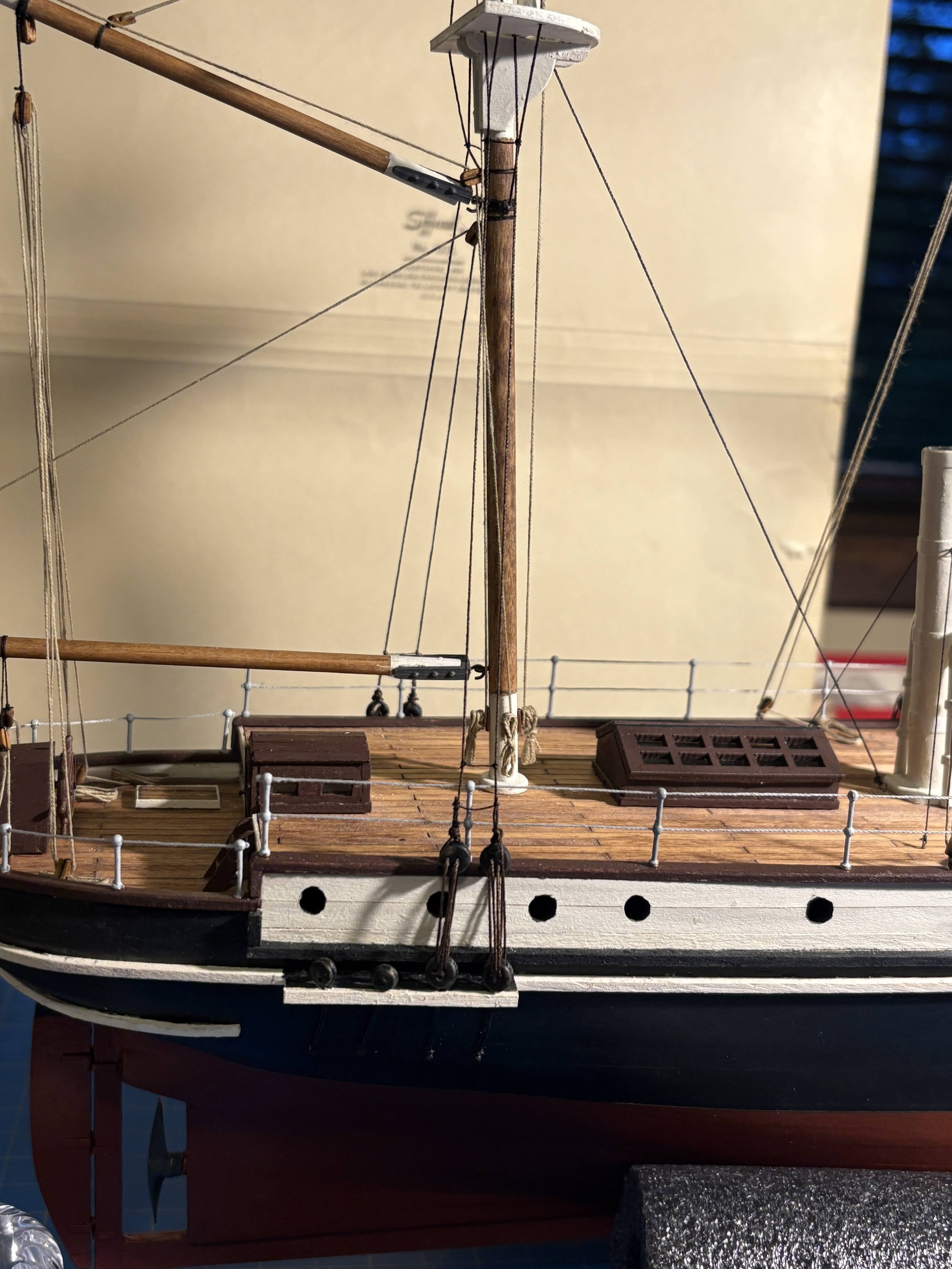
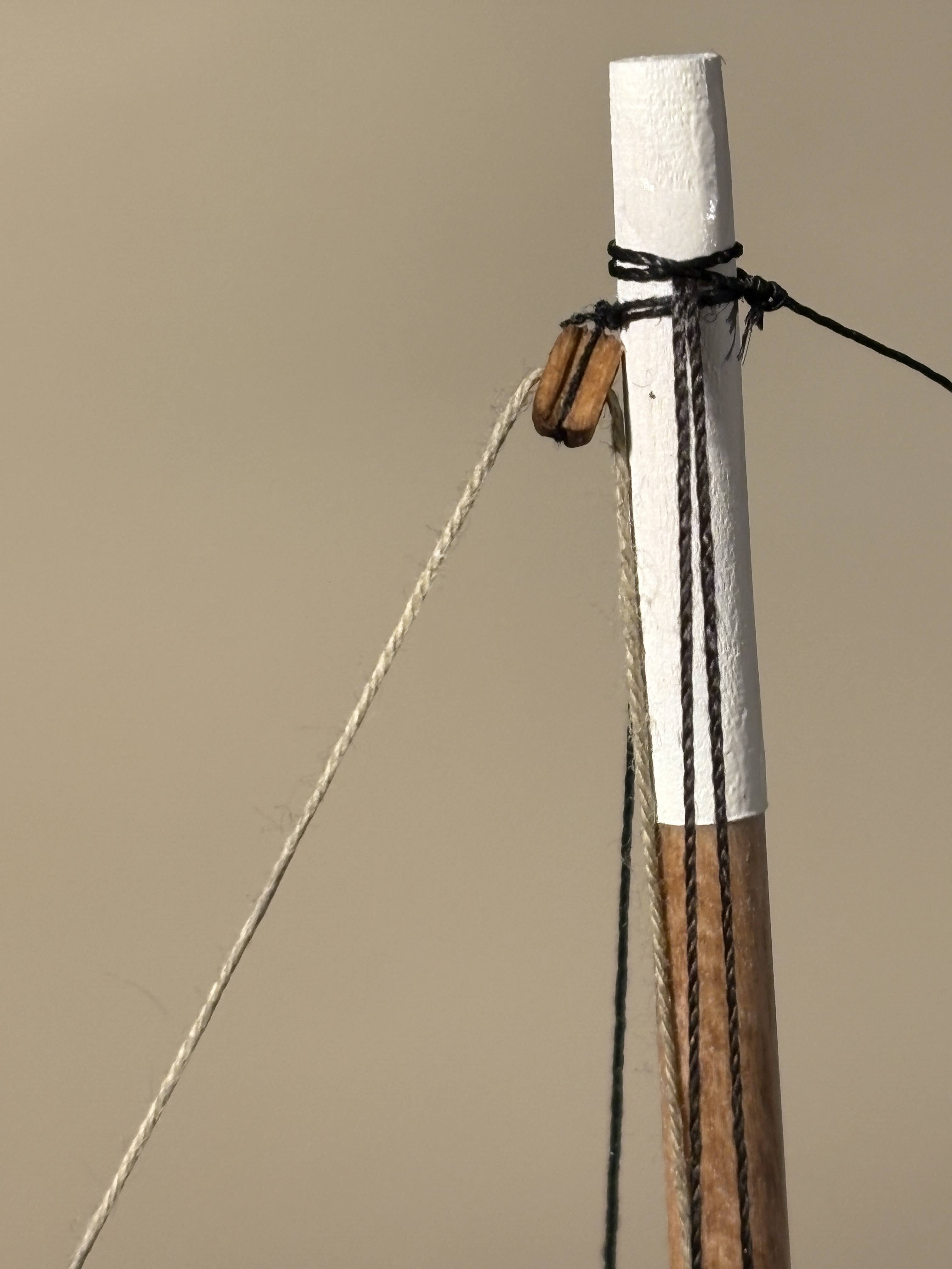
Mizzen mast running rigging . . . Last summer (post #126 above) I said that I didn’t understand why OcCre included gaff throat halyards when the gaffs were attached to the mast with fixed goosenecks. What I failed to recognize at the time was that gaffs generally are attached to the mast with jaws and parrals, and gaff sails are usually brought down by lowering the gaff (to the boom if there is one), which requires both throat and peak halyards. Maybe I should have attached the gaffs on Endurance with jaws and parrals, but it’s a little late to do anything about that now. After a somewhat cursory search, I haven’t found any Frank Hurley photos to confirm whether I’m right about any of that. But if I’m correct, then it appears that OcCre (and I) erred in placing the foremast gaff above the lowest yard, where it can’t be lowered to bring the sail down, or it can’t be done without lowering the yard as well, which seems unlikely. Maybe that gaff should be attached to the mast below that yard, not above it. The first running rigging I installed on the mizzen is a topping lift, running from the outer end of the boom to a block just below the gaff gooseneck, then down to a cleat at the foot of the mast. If I had been thinking about what I described above, I would have placed the block on the mast above the gaff, not below it. I did this and what follows with the mast off the ship, slipped into a hole in a 2 by 4, as I did with a lot of the running rigging on the other two masts. All but the final photo in this post are with the mast only dry fit on the ship. I am not installing sails on my Endurance, and as I mentioned in a prior post, I am keeping the rigging simpler by not installing most rigging that attaches directly to a sail. However, I decided to make an exception for the topsail that is above the gaff on this ship. For whatever reason (or perhaps no logical reason), I liked the idea of suggesting a sail up there, even though I wasn’t installing one. So I ran a halyard through a block at the top of the mast and an outhaul through a block at the outer end of the gaff, and attached the ends of each such line to the other. Assuming there would be something like a snap shackle at the end of each line to attach it to the sail, I simulated a pair of such fittings with a pair of linked tiny rings. So that the gaff will be firmly secured in place, I won’t secure that halyard and outhaul to the cleats on the mast until I have secured the gaff sheets to blocks and cleats on the deck. The base of the mizzen mast fits into the slot built for it long ago with some wiggle room, which sure is better than no wiggle room and misalignment. As can be seen below, to get the mast rake right, I pulled it forward with some thread at the top of the mast, gently weighted with some mini clothespins (they’re only about an inch long; somehow they look a lot longer in the photo). And I leaned an eraser against the foot of the mast to get it aligned with the other masts. All that after fitting the mast into its hole and slot with a gob of wood glue at the bottom.
.thumb.JPG.34d856b5a87e854a56badbe5afa5d94c.JPG)

- 183 replies
-
- 5
-
-
- Endurance
- Shackleton
- (and 1 more)
-
Tomculb reacted to a post in a topic:
Endurance by Tomculb - OcCre - 1:70
-
Tomculb reacted to a post in a topic:
Endurance by Tomculb - OcCre - 1:70
-
Hi Mark. No, I haven't thought of anything I want to do with those kennels, even though I agree with your characterization of them. Maybe I should put some thought into that. Probably wouldn't add dogs, because then I'd think I need to add people, and I don't really want to do that. Different subject . . . I took a look at your Lynx log, which is coming along really nicely. I'm about 80% sure that my next build will be Vanguard Model's Baltimore Clipper Grecian. Despite the fact that Vanguard models are highly detailed and result in beautiful models, I may do some modifications (mostly cosmetic) to make my model more of a generic Baltimore Clipper instead of the specific one Vanguard chose to model. To get ideas, I've been looking at other Baltimore Clipper build logs, along with pictures of and articles about other Baltimore Clippers. So far, this is only fun window shopping.
-
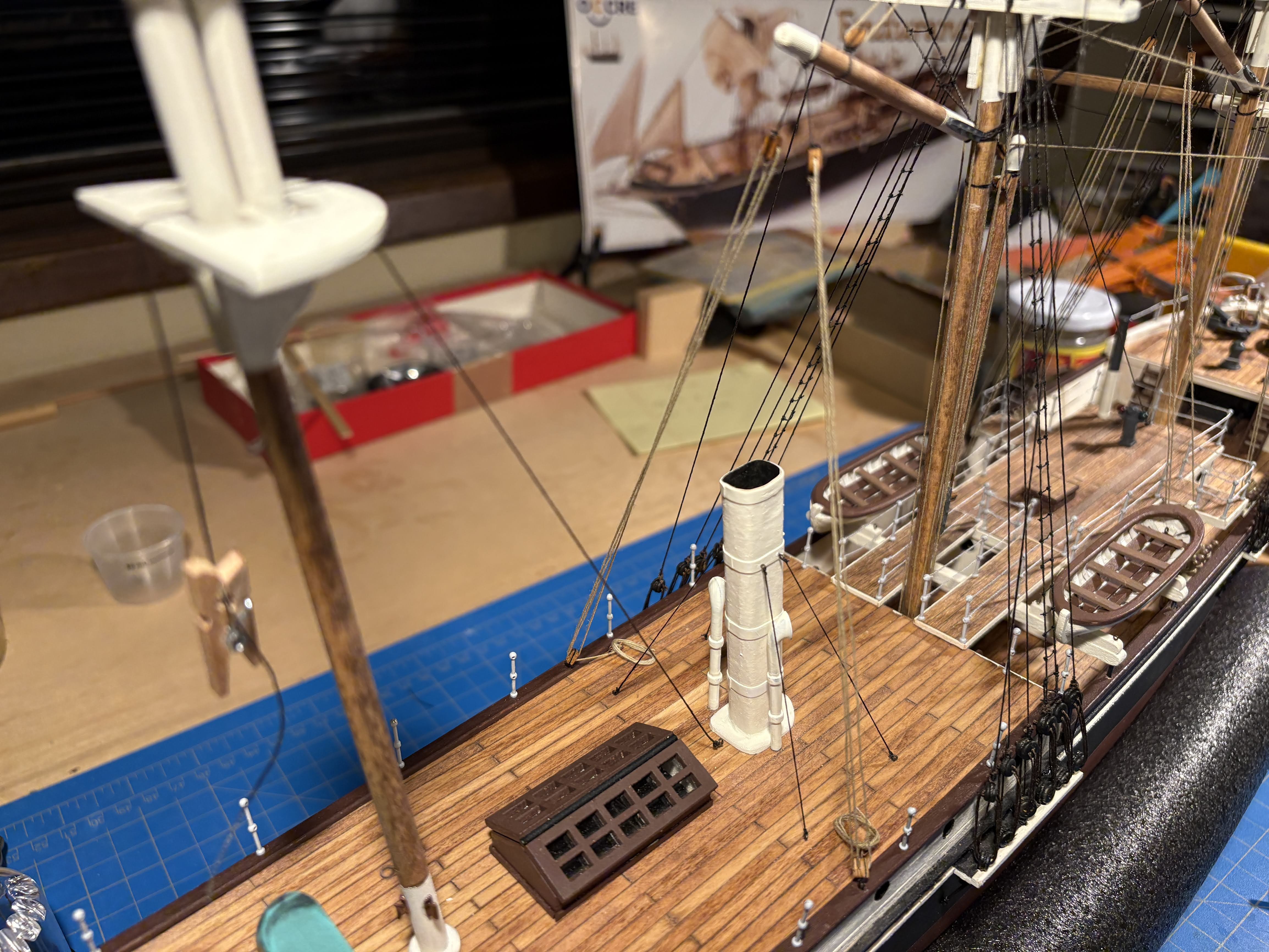
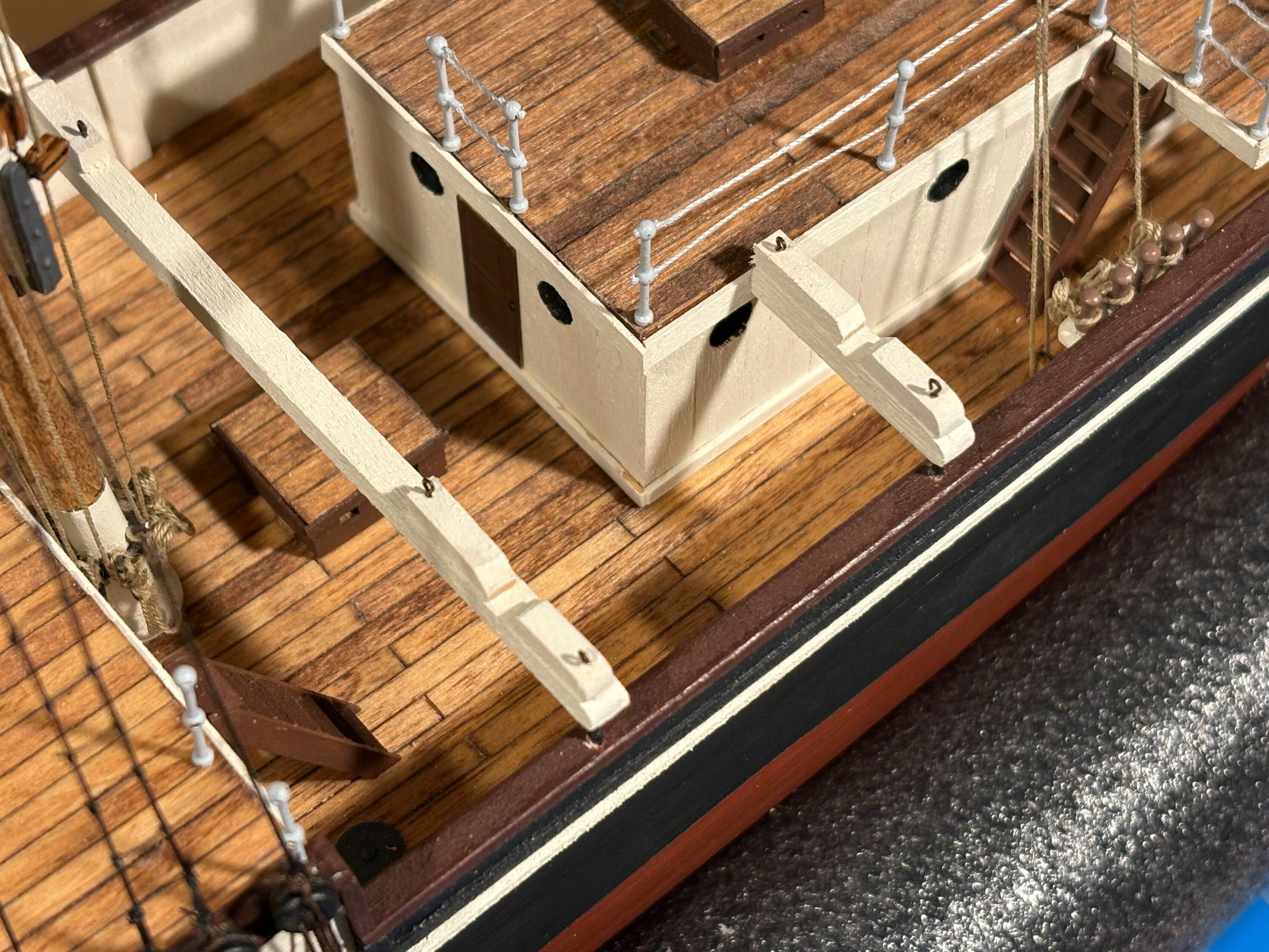
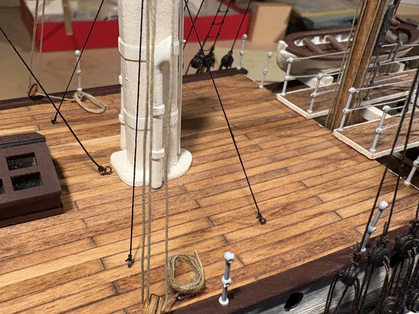
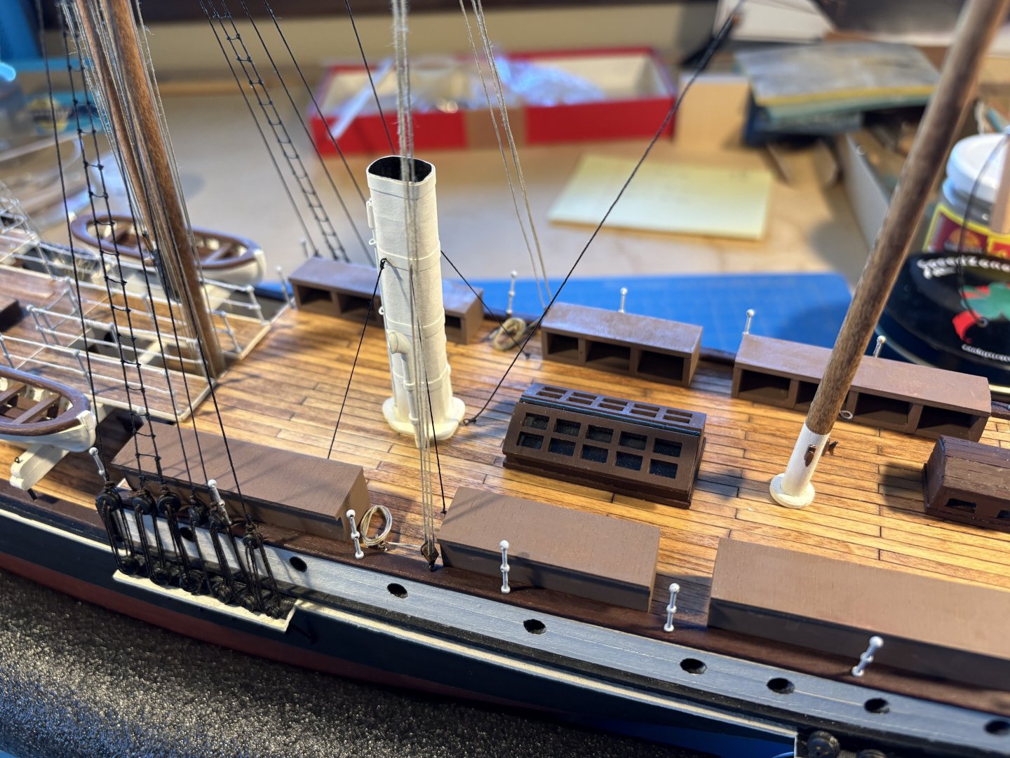
Before rigging the mizzen mast, I needed to finish rigging the main mast; that is, I needed to rig the gaff sheets that have been hanging from the main gaff for a few months now. OcCre has you simply secure them to eye bolts installed in the outer edge of the deck, but as I have said before, securing running rigging that way just doesn’t seem right to me. I decided on a double block (secured to an eye bolt at the edge) and a cleat (glued to the deck). OcCre doesn't supply cleats, but I had ordered some online knowing that I would need them. Rigging the sheets that way meant I had to make a decision about the dog kennels. As the kit is designed, they get in the way of any rigging of those gaff sheets. Personally, I don’t like the look of those kennels anyway, but they were certainly part of Endurance once she headed south from Buenos Aires. What to do about the kennels has rattled around in my brain for a long time now, and I couldn’t put off the decision any longer. What I decided to do was break each of the two strings of kennels into three parts, leaving some space for rigging and for access to the two aft ships boats (yet to be built and installed). Not historically accurate, as reflected in Frank Hurley’s photographs, but then the two uniform rows of kennels as contemplated by OcCre isn’t very accurate either. The kennels reflected in those photos are pretty ramshackle and haphazard in appearance. Once the kennels could be placed I was able to secure the gaff sheets as described above. I also installed stays for the funnel. And I secured the lowest stay between the main mast and the mizzen to an eye bolt just behind the funnel. Now I can start to work on running rigging for the mizzen mast.


- 183 replies
-
- 2
-
-
- Endurance
- Shackleton
- (and 1 more)
-
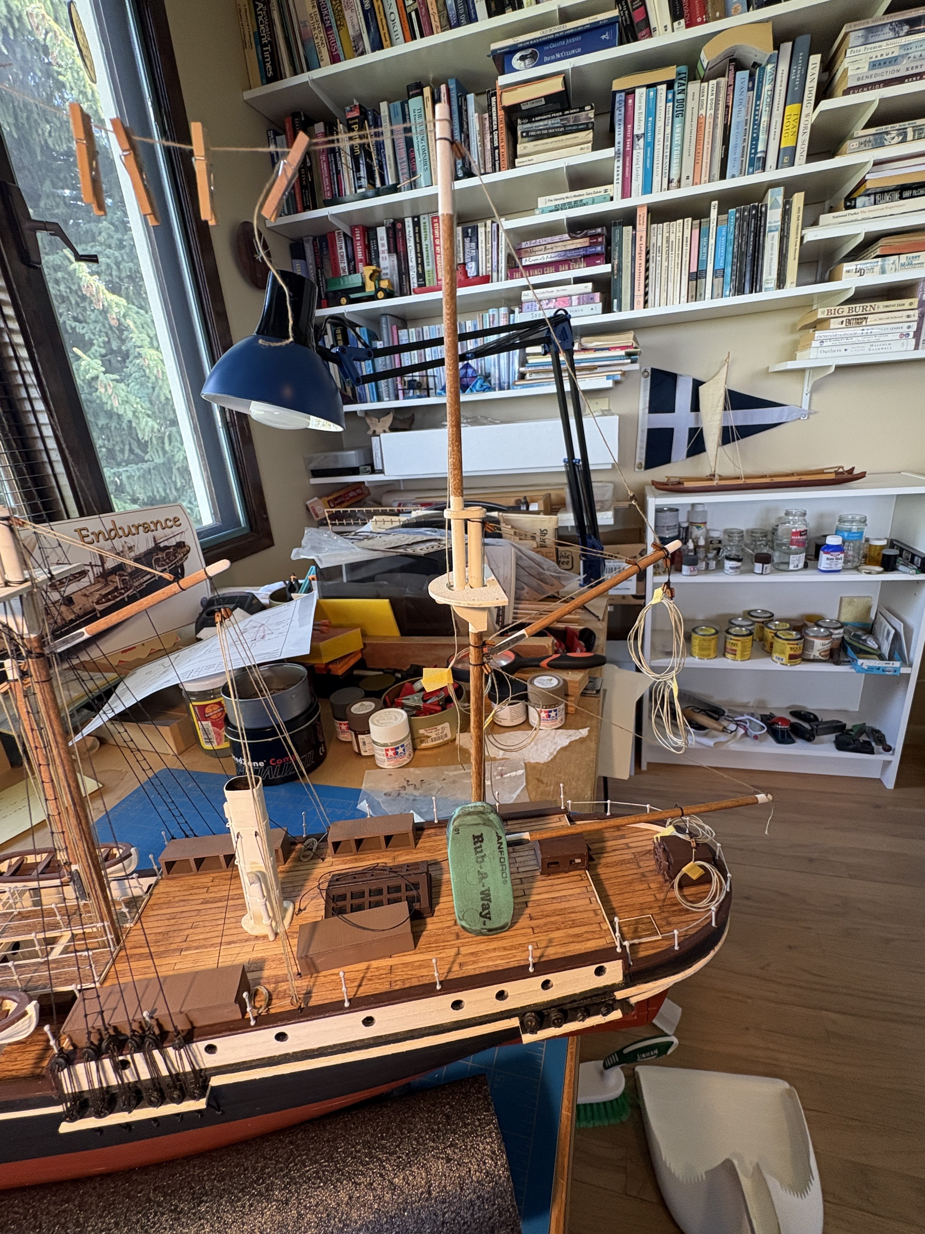
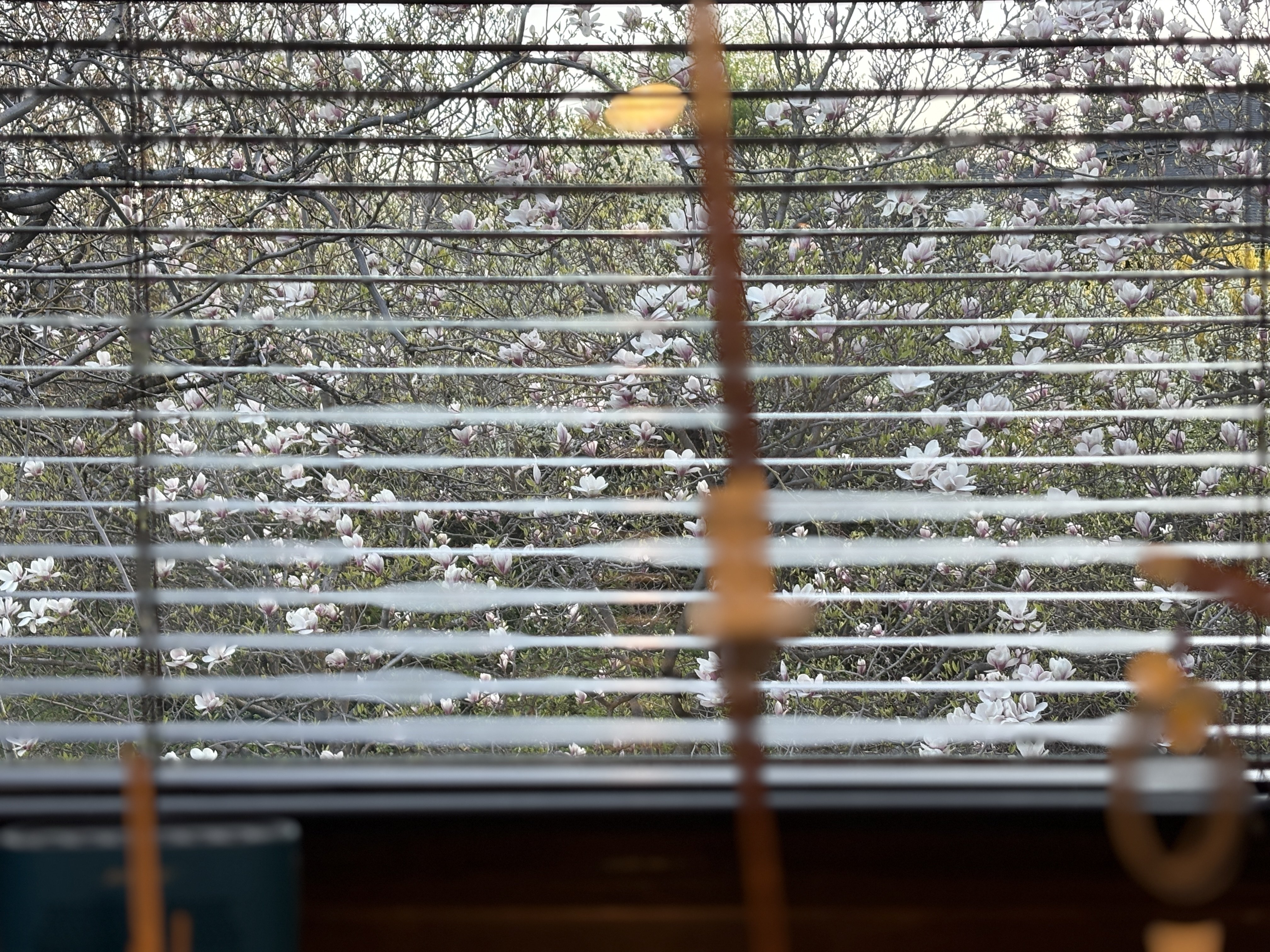
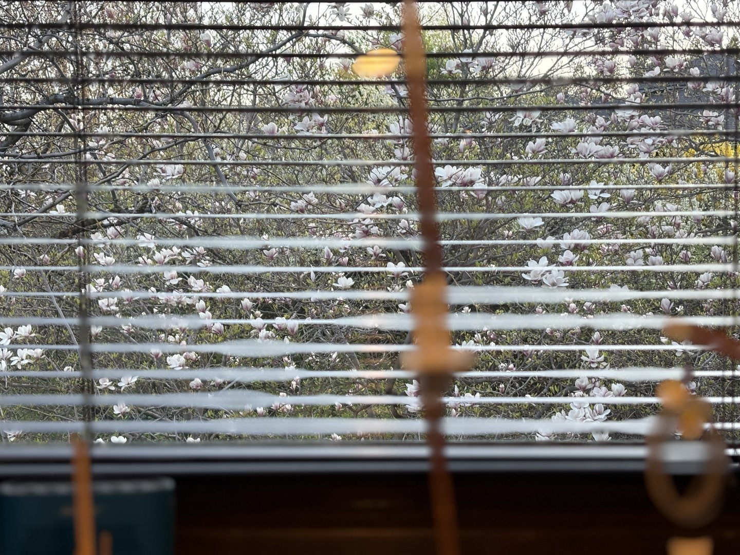
Quick update; the mizzen mast has now been assembled. The base of the mast has a slot that it fits into, deep inside the hull. That slot leaves a little wiggle room, and the eraser you see in the photo leans against the mast pushing it forward enough to have its rake conform to the other two masts. Obviously not glued in place yet, and it won't be until I have blocks and any other fittings tied to it. I may also rig the gaff and boom before gluing the mast in. Every spring for a week or so I am treated to our magnolia tree in full bloom, out the window behind my shipyard. The picture doesn't do it justice . . .

- 183 replies
-
- 4
-
-
- Endurance
- Shackleton
- (and 1 more)
-
Your model is progressing really nicely. Planking the inside of the bulwarks looks really nice. As I mentioned in my log, I wish I had thought of doing that. I admire your willingness to try many varieties of things (ladders and doors most recently) to get just what you want; I don't have that patience. From the look of things, you trashed some ladders I would have found quite acceptable. Keep up the good work.
-
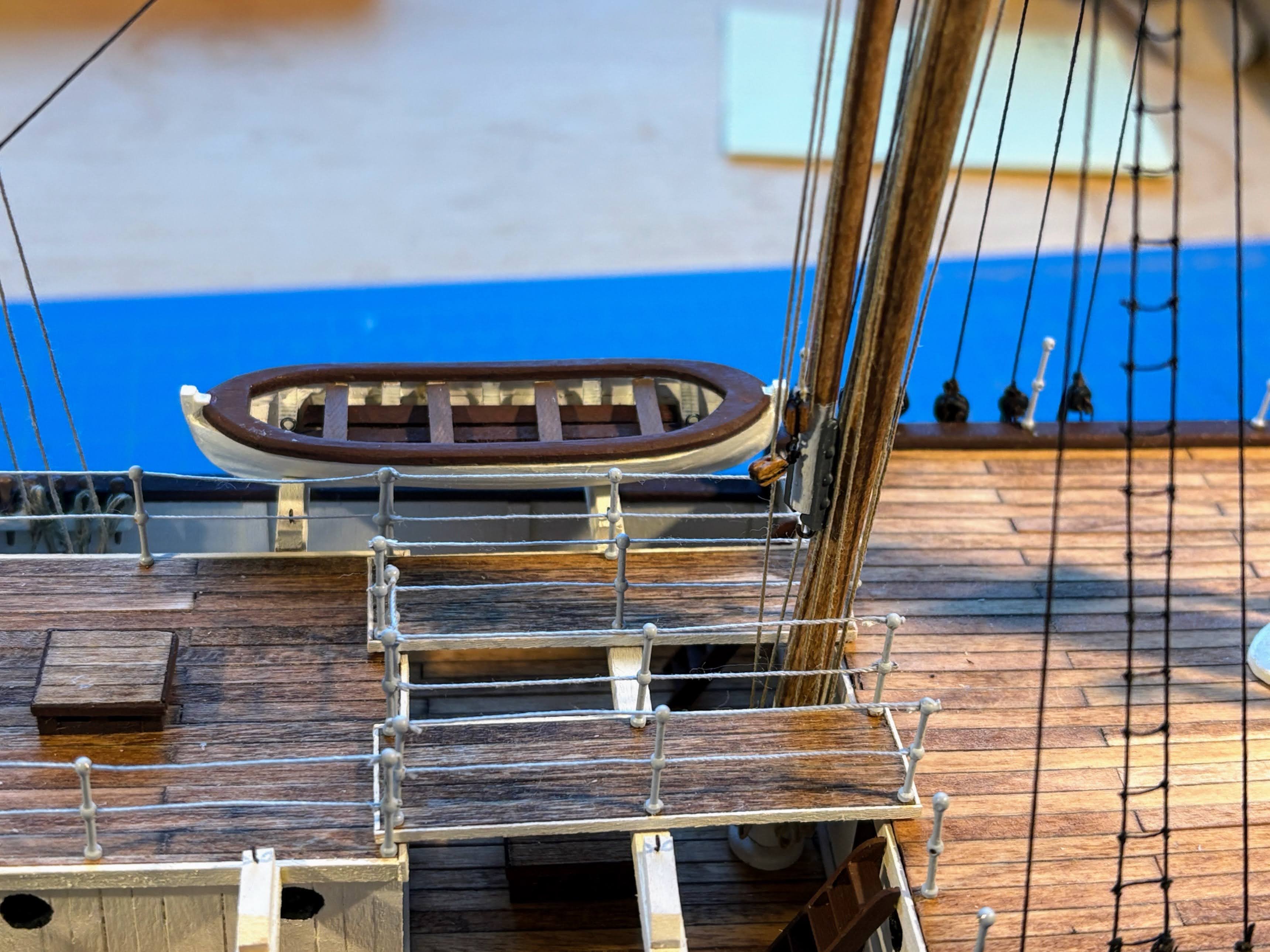
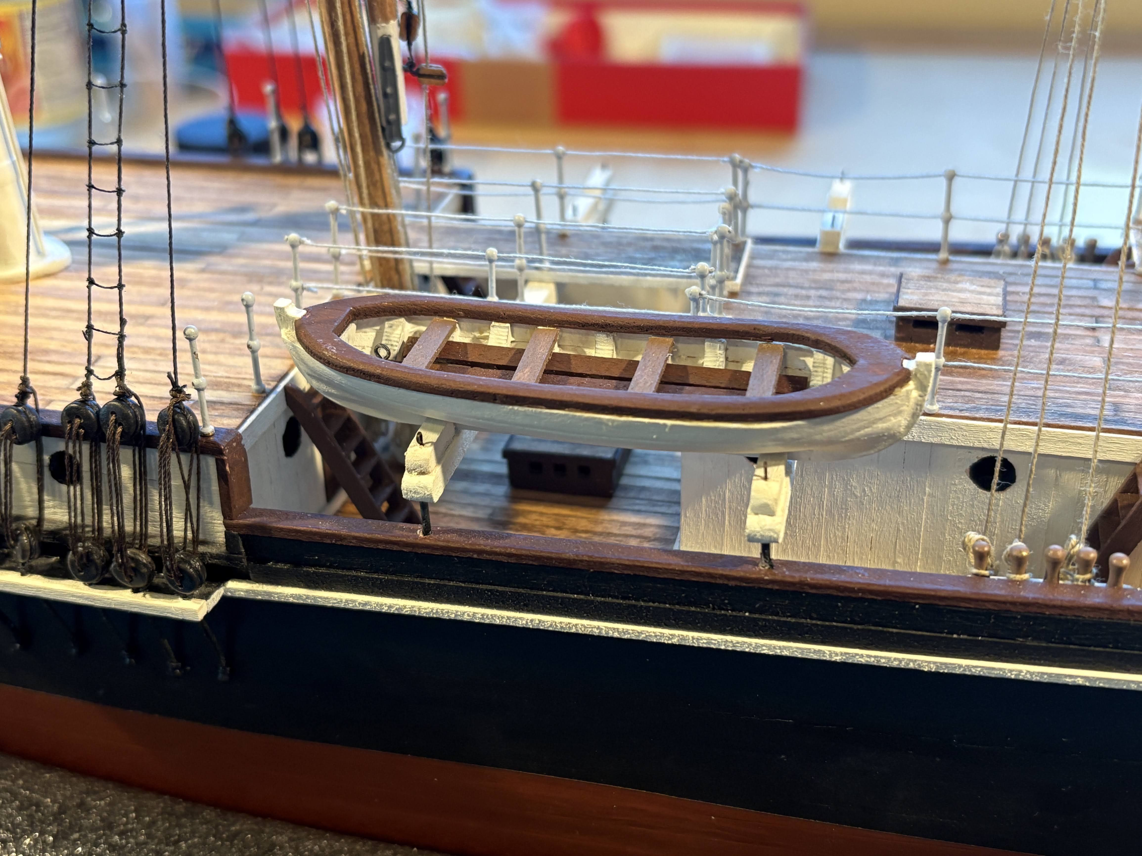
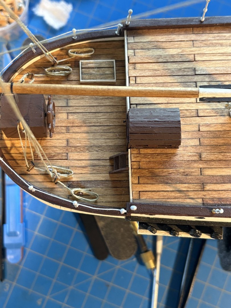
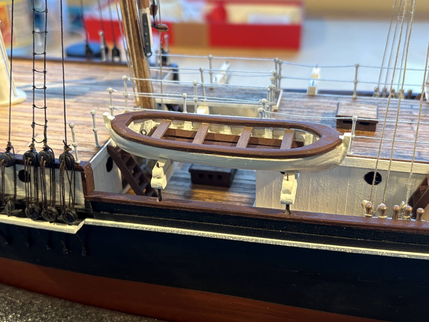
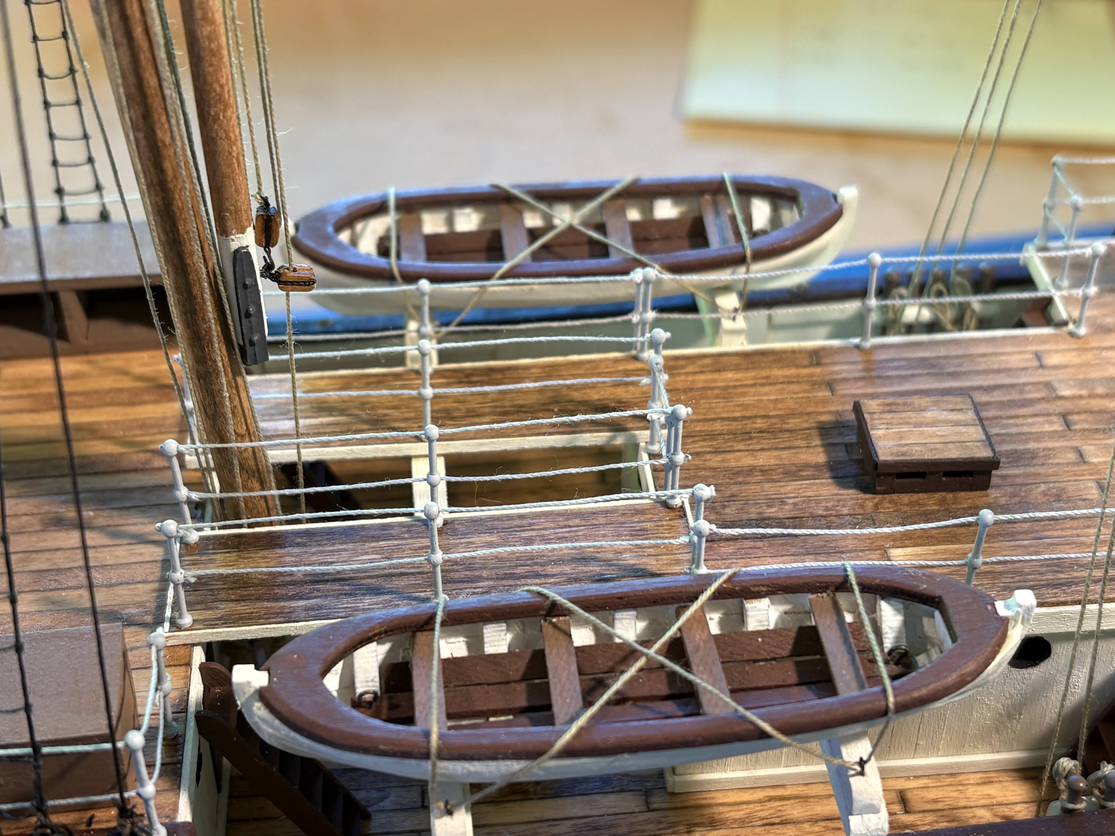
The second smaller boat has now been completed and placed onboard. The first one has been moved to the port side. Neither has been glued in place yet. Now on to something completely different: the mizzen mast.
- 183 replies
-
- 6
-
-
- Endurance
- Shackleton
- (and 1 more)
-
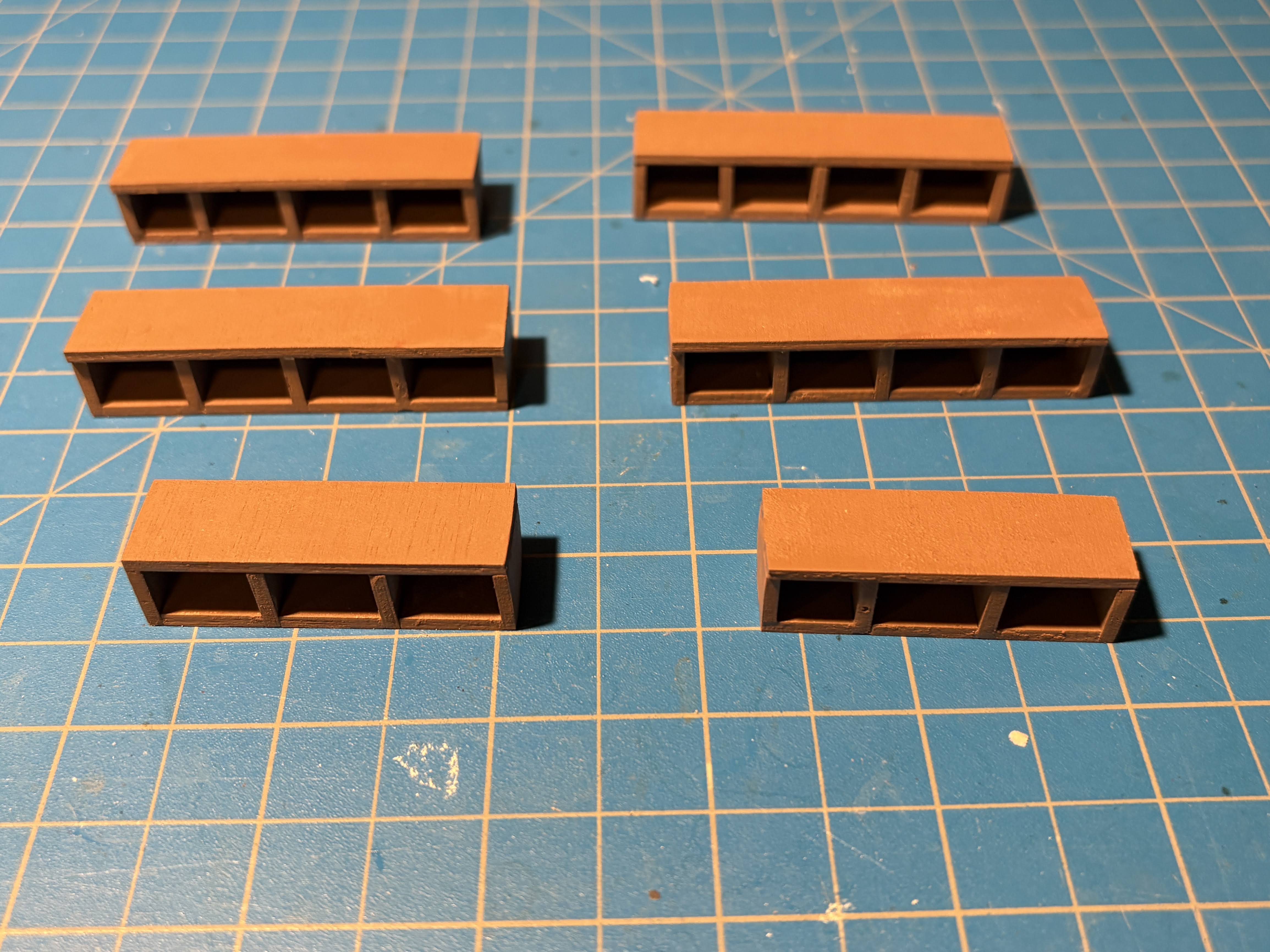
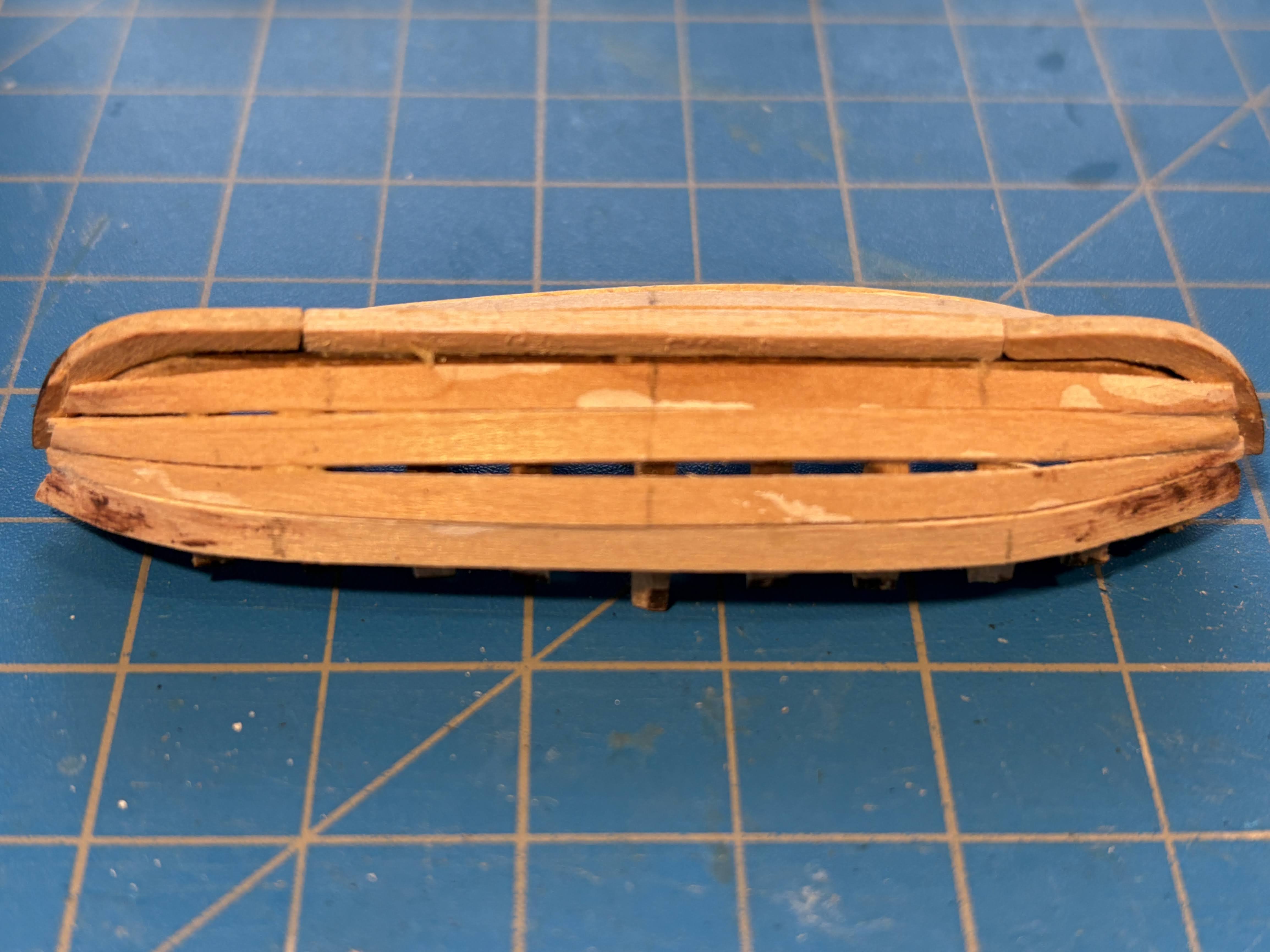
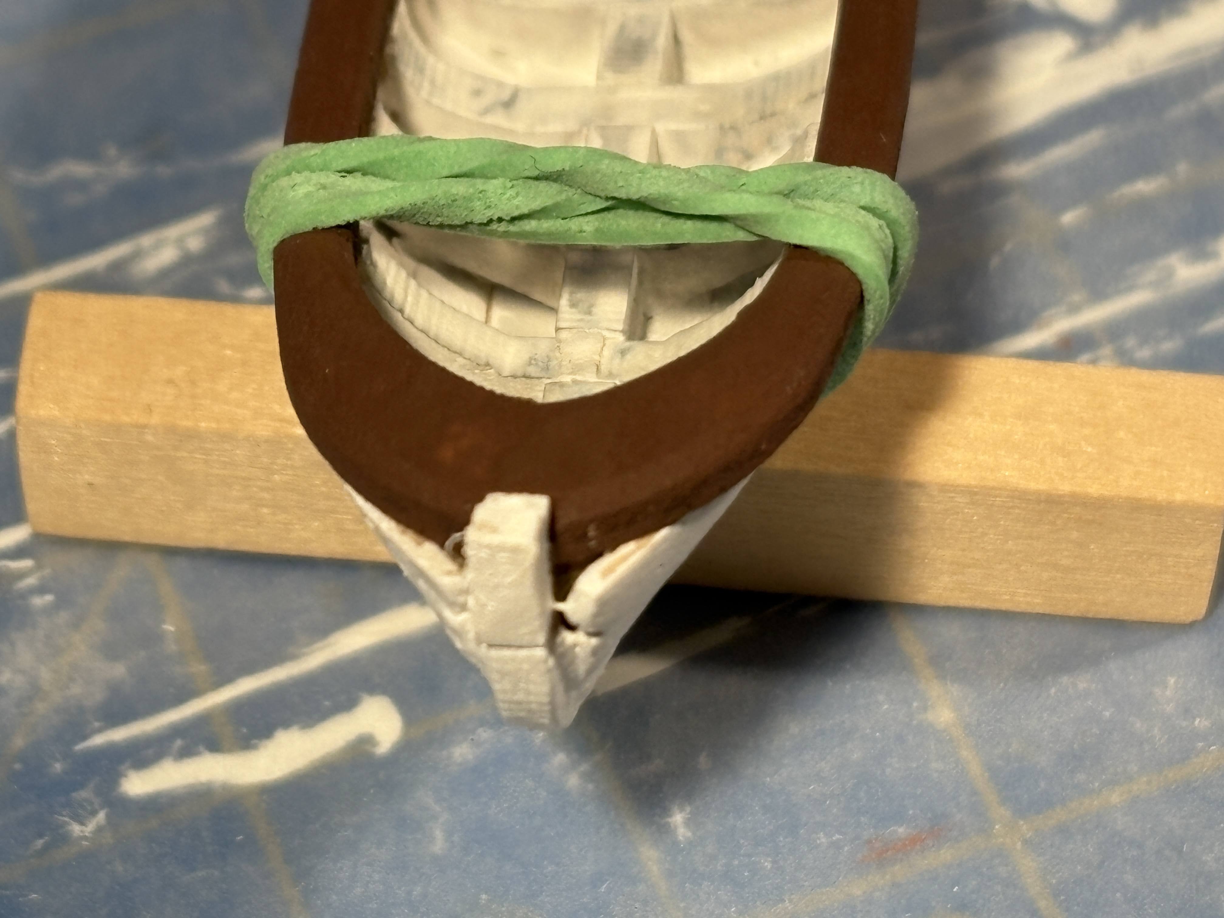
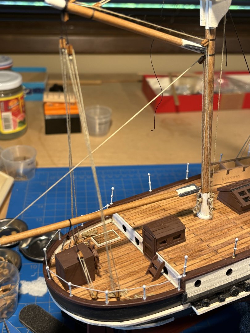
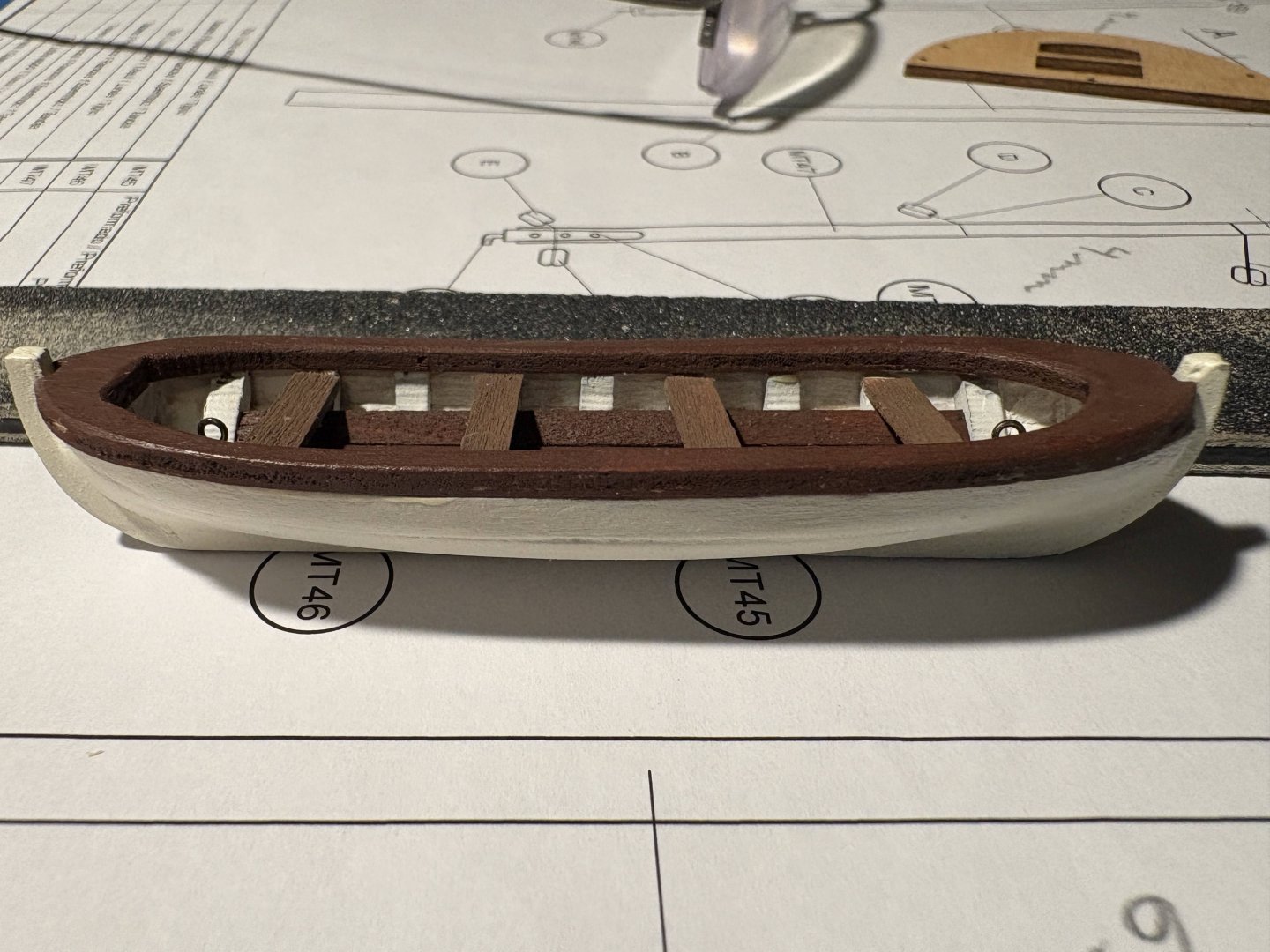
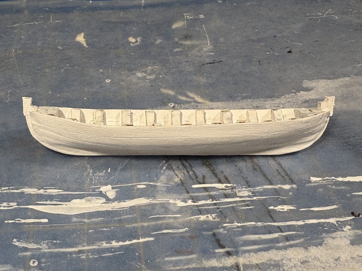
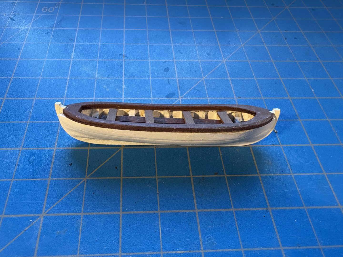
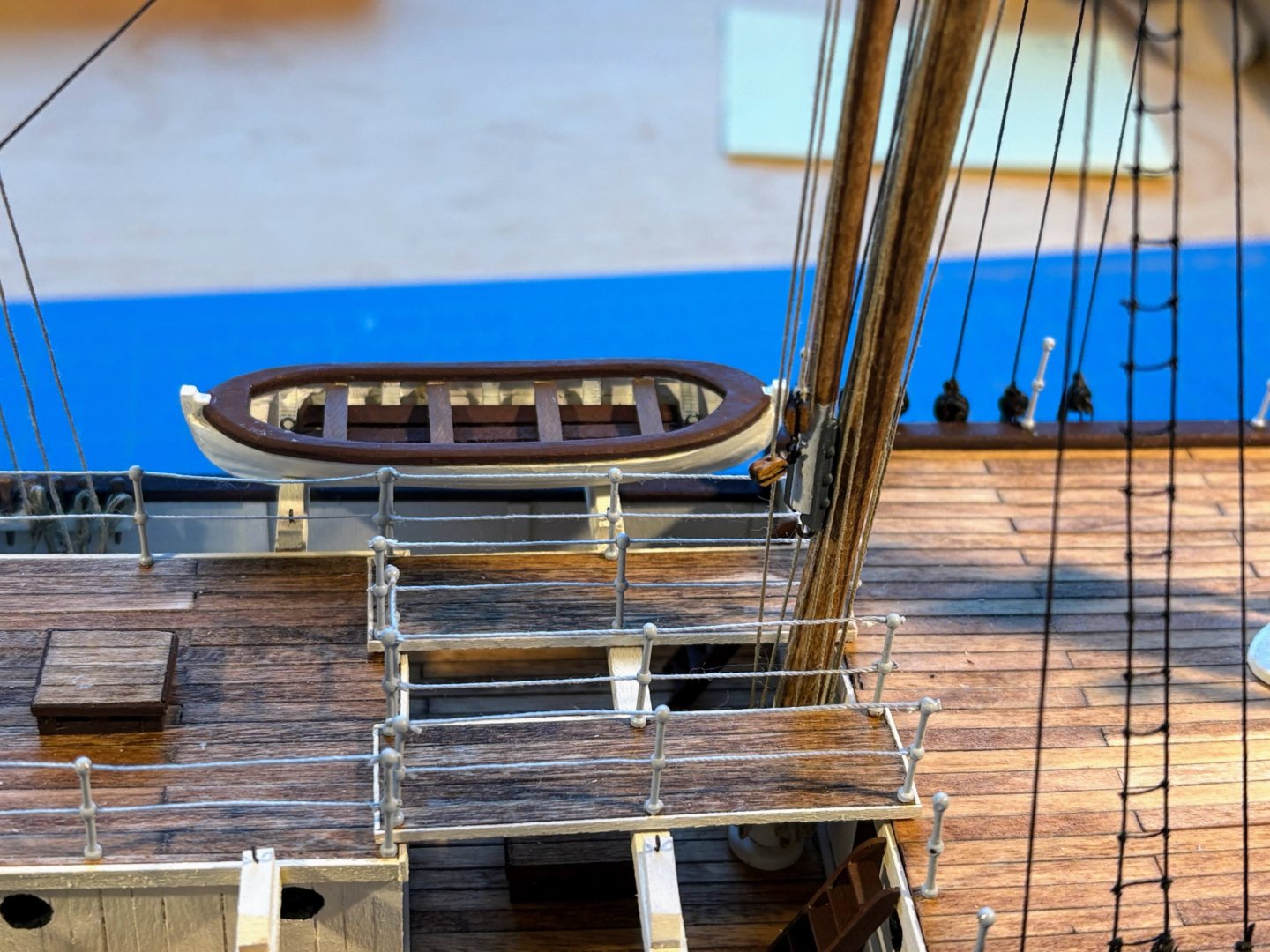
After an unfortunate mistake and some travel interruptions, I have now finished one of the two forward ships boats. As I mentioned in an earlier post, I chose to stow the forward boats inboard rather than hanging outboard from the davits as OcRre does, and chose to stow the smaller pair of boats forward, since the larger boats barely fit forward and inboard. I used some 1/32” strips for planking, since they are slightly thinner and bend more easily than the OcCre supplied 1 mm planks. As usual for me, the planking job looked abysmal and required much sanding and filling to hide my lack of skill when it comes to hull planking. The ugly . . . Now for my big mistake. The laser cut stem pieces have a longer end and a shorter one, and without noticing that difference, I glued them in place with the longer ones running along the bottom of the hull, which wasn’t correct. I found nothing in the instructions alerting the builder to this important distinction. In the following two pictures I have added tiny 2mm x2mm pieces to bring the stems above the laser cut rail cap piece as intended, but I still have some sanding and filling to do to make things look acceptable. The bad . . . And finally, after installing flooring planks, seats and the rail cap, the good . . . Some months ago I built the structures to stow these boats inboard, and I have now glued them in place, after adding eyebolts for the lashing that will hold the boats in place. The planks that run between the two decks are dry fit in place for now, as is the one boat I have completed. Now on to that second boat, with the hope that I have learned some things that will make things go more smoothly.


- 183 replies
-
- 4
-
-
- Endurance
- Shackleton
- (and 1 more)
-
Great work Giddy, and glad you have found my build log to be helpful. A few comments . . . I like the color of stain you chose for the deck planking; it looks really authentic and certainly better than what I chose. Based on several recommendations on these boards, I use Birchwood Casey's Brass Black to blacken virtually all the brass on my models. Search the name on the MSW website and you'll find a number of tips on how best to use it. It's a pretty easy process and the results are good. Endurance had a wooden railing on top of the stanchions at the stern, which I overlooked when I installed those stanchions. I keep telling myself that I should go back and clip the tops off the stanchions (eliminating the upper cable), cut out a wooden railing using my jewelers saw, somehow drill holes in the right places to accept the tops of the stanchions, and glue the wooden railing in place. I haven't yet built up the courage to do that. If you choose to do so, it looks like you still have the opportunity to use the laser cut railing that OcCre supplies and has you install at deck level, and install it on the tops of the the stanchions instead. Or copy the supplied railing to make a second one for the top. I look forward to following your build. Tom


.JPG.9c57fb6a43b688bb5fb0e4ae2c35a27e.JPG)