

theoracle09
-
Posts
152 -
Joined
-
Last visited
Content Type
Profiles
Forums
Gallery
Events
Everything posted by theoracle09
-
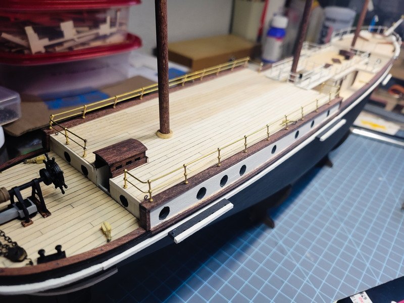
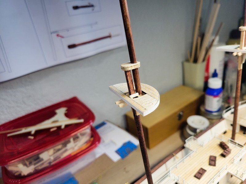
 Hi folks, thank you for the likes and comments. Progress continues as all 3 masts have been built and stained, but they still need painted and blocks installed. That'll happen today, along with the mizzen deck railings. I started with the railings after my previous update but got seriously burnt out on soldering (punny!). So I switched gears and started tapering the masts. The plans call for a simplified mast construction with cheeks, 2 crosstrees, ply platform, and ply mast top. I added the small fore piece based on Frank Mastini's 'Ship Modeling Simplified' and also planked the top. I also added (book isn't in front of me...I think they're bollards?) rounded-over 2x2mm next to the lower mast for the shrouds to lay against. Since I squared off the top of the lower mast, I also planked the top of the mast cap, so the square lower mast doesn't slip through the cap. The cap is glued to the top mast, and everything else is glued to the lower mast. In this way, I can separate the two assemblies and install seized blocks before it all gets glued together. Additionally the bottom of the top mast has been squared off so as to be inserted into the mast top. Everything is snug, so I can install into the deck and check alignment without gluing the masts together, or to the deck. The plan is to do as much rigging as possible off-ship, and then install the entire thing when need be. As for the mizzen railings, it's a really simple task which takes time since I'm building it on the model instead of on a building board like I did the quarter deck house (formally called ritz). I thought I'd be able to bend the stanchions to achieve the required angle as on the real ship, but the wood wasn't happy about that so I had to pull each one individually and bend them 1 by 1. The port side is soldered and needs cleaned, the starboard still needs soldered. Then I'll airbrush the railings, masts, and booms all at the same time. Lastly I've decided not to push for realism for the rigging because I'm in a bit of an odd situation when it comes to building experience, as rigging is where the experience trails off. Endurance will be my 3rd hull completed, but I haven't rigged any of them. My first project, San Francisco, was 'lost at sea' unfortunately during a move (the log is in my profile if anyone wants to see it from 10 years ago). The Newport is on the bench as a 95% completed hull when I started the masts but didn't have a lathe at the time so the dowel broke. I had to order dowel from overseas which arrived a week or two ago, so progress can continue on the Newport at some point. All of that to say, I am going to use Endurance as a learning curve to the rigging so I'm not focusing on installing every little line on the square sails. As mentioned @HakeZou has blazed that trail and I'm more than happy to follow his additions for this ship, which are plenty and add a lot to the rigging plan OcCre provides. So please forgive the historical inaccuracies (if any, I haven't researched it or traced the rigging yet). I have a strong suspicion Terror and Erebus are in my future and I can see from the logs there are a ton of opportunities to bash/upscale, so for future projects I'll have more experience with the rigging and would be more comfortable adding things.
-
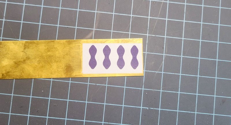
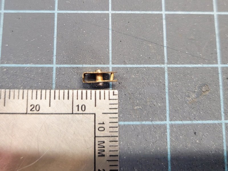
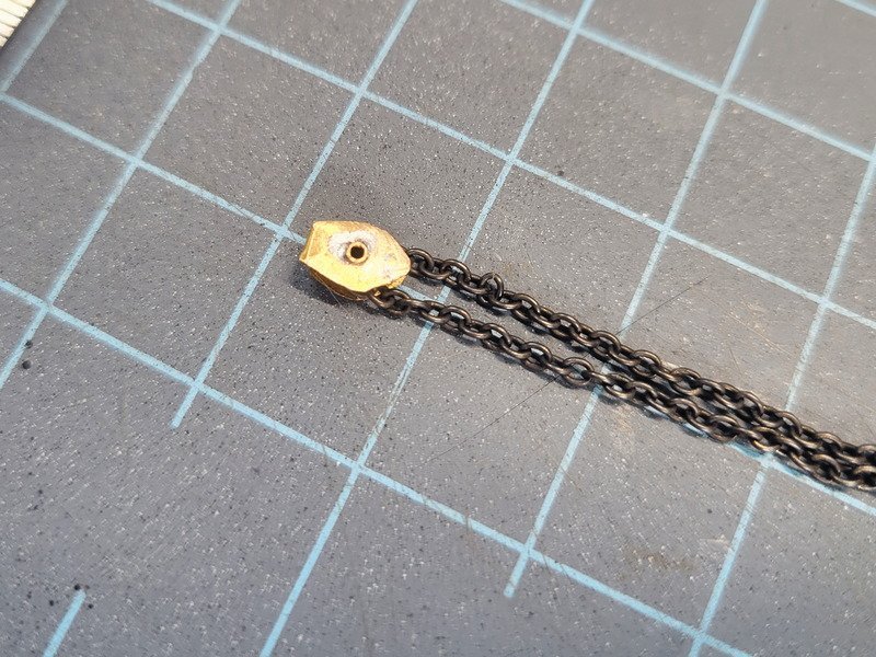
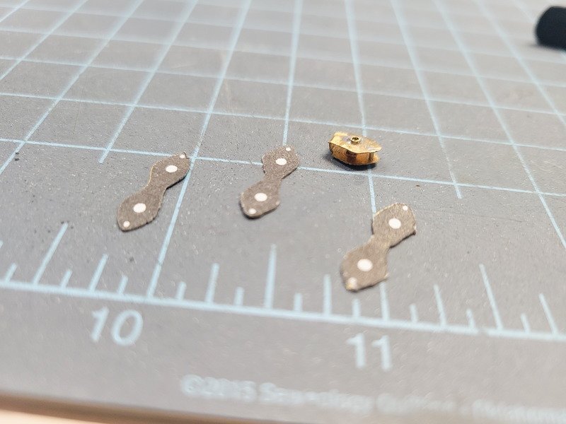
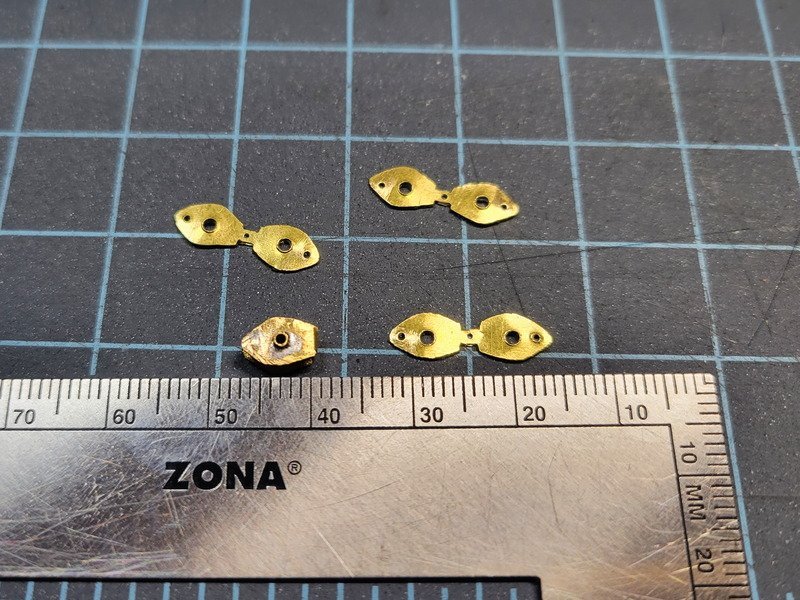
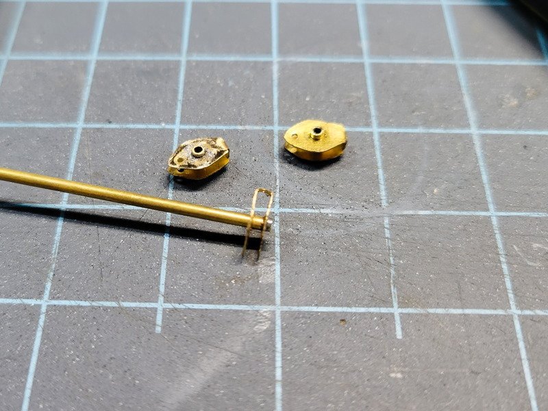
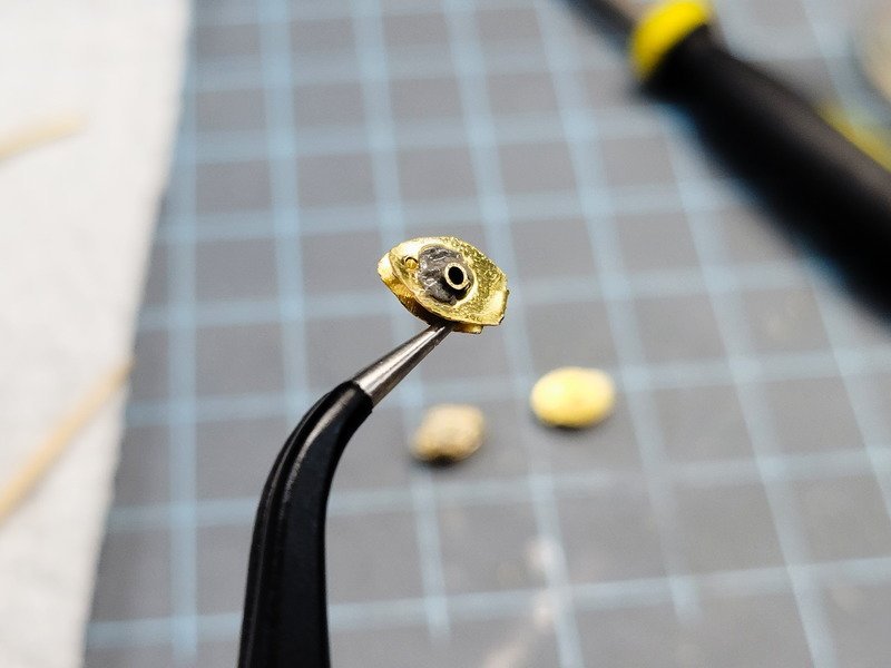
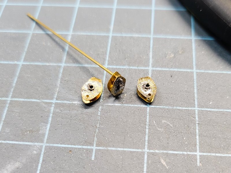
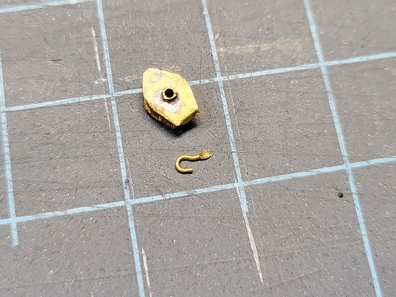
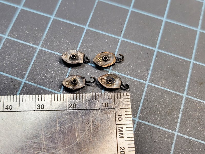
Another huge picture update for a small detail, but I have learned a ton from people taking the time to document their processes so I want to give back and do the same. I'll post the finished pics first so you can skip the rest if you'd like! The steering gear is now complete. It's not exactly so scale but in my honest opinion it's a better detail than the tiny deckhouse thing occre will have you build. I had fun building it, but I'm ready for a break from working on tiny brass parts! To begin, I used the same steering gear pic I've posted previously and made a 2D image in Inkscape that looked like the outline of one of the chain blocks. I printed it out and used adhesive spray to affix to 0.2mm brass sheet. I wanted to cut the entire block out in one go, then fold it over to create the 3D shape. I only made 1 block at this point, as a prototype to see if it were possible and if I had the patience for 3 more afterwards. Note the smaller diameter rod in the next pic, it's slanted a lot. Looks good, so I documented the rest. I marked the drill holes by hand on the first one which wasn't accurate at all (but you can't tell once the chain is installed anyway) so I changed the pattern to include the holes and then cut out the remaining 3 with a jeweler's saw and bench pin. Starting out (with a 4/0 blade) I kept snagging on the down stroke and it was annoying. By the 4th one I had figured out the pressure (or rather, lack of pressure) needed to make continuous sawing motions. It was good to learn. Holes drilled and the pieces shaped using needle files. 1.5mm brass tube was used as the bigger rod. After folding the pieces I put 1 on the end of the tube and soldered. Then cut it off the tube and soldered that end. I used a liquid flux and a low-temp silver solder paste. It's the only paste I have and worked better than using regular solder. Here's a close up of what it looks like before I touch the iron to the rod. My iron was set entirely too high so you can see the flux (and paste solder too I think) boiled immediately when I applied heat. I turned the iron down once I realized this. Next step is affixing the 0.7mm brass rod in the same way as the 1.5mm brass tube. The smaller rod was filed all the way to the brass sheet, so you can't see it unless you look close. I should've left some sticking up, like the middle tube, to better match the pics. Additionally the blocks didn't have holes in the middle of them...so I should've soldered them closed or used rod, not tube. Hooks were fashioned and then the end squeezed in pliers. Blackened. I like the 'weathered' look from the splotchy blackening. If I spent more time cleaning (including sanding/filing) I'd have a more consistent result, but by this time my concentration was fried and I just wanted to be done. Based on the size of everything I laid the plans down right next to the stern and figured out where eyebolts need to go. I didn't want it to interfere with the two seized wooden blocks that are yet to be installed. Running the chain through the blocks should have been a dream, and it was, until I put the hooks in. I didn't bend the smashed portion 90* so it interfered with the chain running through. This made installation infuriating. In the process the outboard port block lost its hook, and with the chain already run through and attached to the block it was impossible to remove unless I wanted to risk further damaging things. It's such a small detail I just used thread to tie the block to the eyebolt. I also used thread to tie the chain to the two outboard blocks' 0.7mm brass rod. Notice the port outboard block got solder in the center tube hole. I actually like the look of that; not having holes. But again by this time I had spent many hours shaping tiny parts and just didn't want to go back through and add it then file back to shape. I think it's fine the way it is. Lastly, I installed the chain running over the top of the barrel, not under like in the pics. So I woke up this morning and spent some time breaking the chain, unwrapping from the barrel, then re-installing. What an absolute nightmare. The original length was too long because it wrapped over the top so I had to remove some links to make it connect. I think if I were to really pull on the chain I could remove 1 link and get it tighter, but there's no chance I'll attempt it. It is what it is as you see in the pics. Thanks for reading!
-
Thanks for the comments on the belaying pins guys, I sincerely appreciate it! I saw someone's Endurance on another site and they added pins but I can't seem to find the darn log again, or the site it was posted on. I'll need to keep researching, and then sit down and trace each line and check off on a sheet each run. Another question: I have Petersson's "Rigging Period Ship Models" but the author notes it's only for one ship during one time period. Does anyone have any suggestions on rigging books that will benefit this model? @HakeZou you posted a link in this post to a manual of some sort, but the link is now dead unfortunately. Would you happen to have a copy? I'm doing a hybrid of sorts. I did not insert eyebolts into the deck before planking as suggested (to wrap the tails under the decks, for security) because I built circular pin rails to be glued to the masts. Clearway mentioned Endurance had eyebolts under these circular racks which would have blocks, then affix to the pins on the rail. You can see this in one of the found wreckage videos. I mocked this up but determined (without replacing the kit blocks) there wasn't enough room so I decided to just terminate at the circular rails.
-
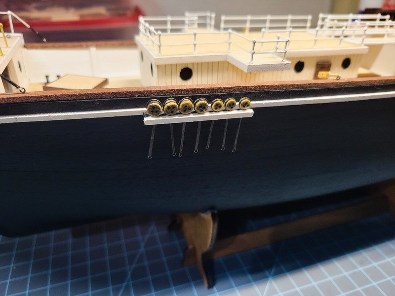
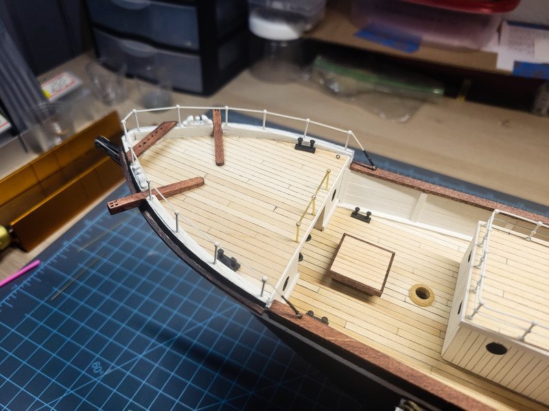
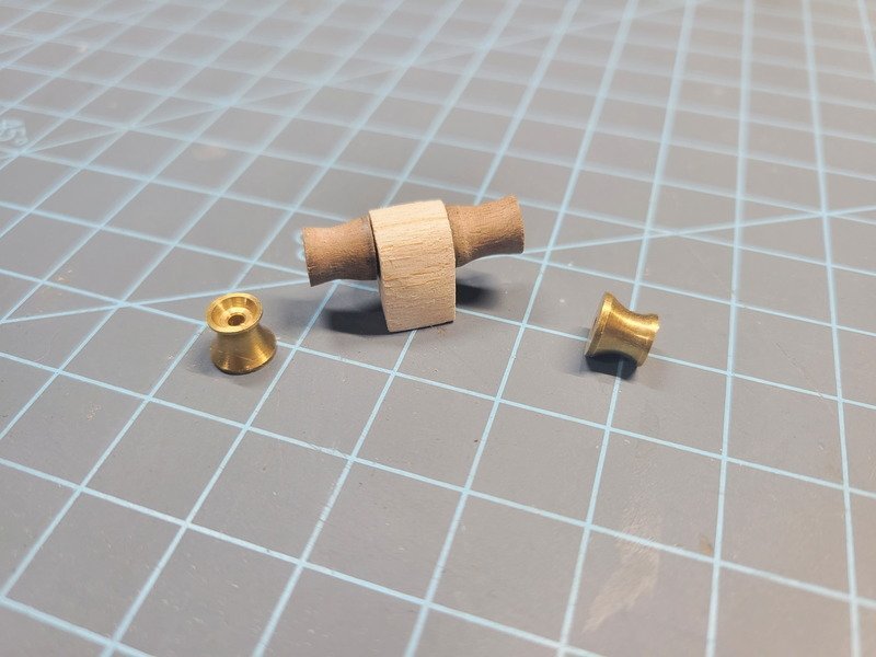
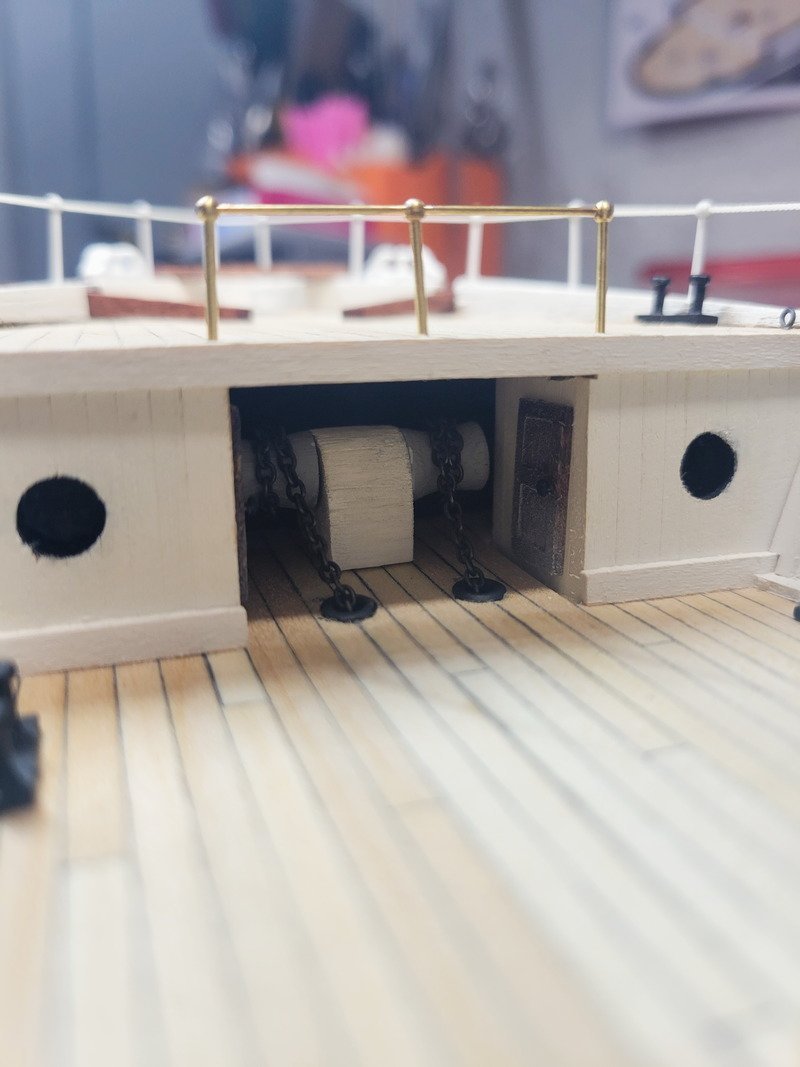
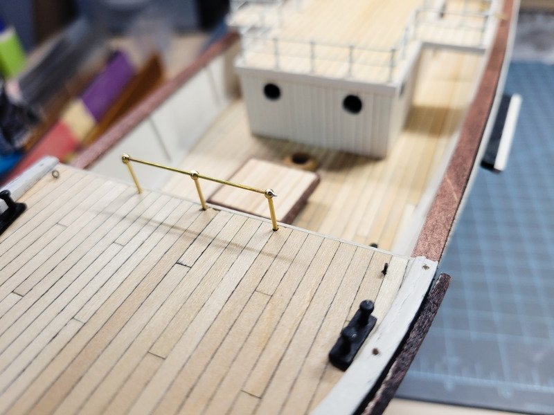
Maybe I'll give it a couple weeks before I mention buying more stuff for the ship haha. I just today got a cross slide for the drill press which I've wanted for some time now and is why I've held off on the belaying pin racks. Speaking of the pin racks, @HakeZou graciously provided me with his rigging excel document as I have no idea about rigging these ships. I pushed some thread through some blocks on a Midwest kit one time, that's about it. I'd like to go as accurate as possible (or reasonable), and I need to go back through Hake's log to see if he added pins. @clearway I noticed on yours I believe you combined the two on the quarterdeck? Do they have the same amount of pins? Before I make the pin racks I'd like to be certain I have enough pins when I start adding things the plans don't include. For the update, there's not a whole lot to talk about so let's see some pics. Rather mild update today. The first set of chainplates have been installed. I stained the deadeyes Espresso, and pretty sloppily at that. They could do with another coat to even out the tones but I've decided I like the striations. The 4 bigger ones have gaps in the strop, but the 3 smaller ones are snug, and were a pain in the butt to get in. I'm thinking I can just sand a small slot on the back side if they really can't go in, then for the starboard side I'd sand the slot on the outboard side so as to be invisible to the viewer. Speaking of I have settled on a background for the display. I'll either find or create an old-timey map on faded parchment of her voyage south, with notes in cursive scribble of where she became encased, her drift route, etc. I'm excited to make something and will definitely post for anyone to use. It'll be a digital graphic that I can have printed. I need to know the final dimensions of the ship first before I begin modeling/planning the case. Back on track next I tackled the bow railings. I used some white Guterman thread and created a 3-strand (2 threads per strand) rope. The port seizing was done on the machine and I tell you, the machine is worth it to build (but you should definitely buy Chuck's version). I couldn't do nearly as good of a job by hand, and I tried (not by choice!). I installed the port eyebolt and ran the tail end through the stanchions which were already faced correctly and glued down. Then I installed the starboard eyebolt and ran the rope through, glued it together so I could cut it, and then sat there wondering how on this green Earth am I going to wrap it 100 times?!? Well I tied a knot and gave myself plenty off the bobbin and started wrapping. It was bad. I couldn't figure out a way to make it happen, so for anyone out there doing this type of procedure, don't glue the stanchions in. Seize one side, thread on the stanchions and install to mark where the second eyebolt is, then take off the ship and use the machine to seize it. What I did, I glued the rope into the first stanchion and cut the end off. Before the cut I smeared CA all over the end to the first stanchion to maintain it's straight shape. I seized it on the machine with massive difficulty due to it's short size and then installed. A tiny dab of glue on the outboard side makes it look like it's a single piece of rope. I found some of those brass bits from another kit and they looked like the right size for the ends of the steam windlass. I don't want to use them now because they're really nice and it'd be a shame to hide them under they deck, so I sloppily made a couple on the lathe. I'm going for the same overall shape as what Tom posted because it's going to be so far under the anchor deck it doesn't need to look realistic. Next was blackening the chain, which worked beautifully. I ran the lengths through steel wool and then dropped into hydrochloric acid for 30 mins or so. They got rinsed in a baking soda/water solution and then dried on paper towel. I don't touch them after the acid, I just use tweezers. Into a small shot glass of brass black and I use a toothpick to stir it around. I've found if you leave the brass is for too long you'll get flakes and the black won't stick. Out of the brass black and into two rinse cups. After drying for a time I ran them through a papertowel, taking off any flaking and buffing at the same time. The image above is after buffing, and no black comes off on my hands and it's nice and shiny. I really doubt that's how big it was on the real ship, but I didn't want to spend a lot of time on something that'll barely get seen, if ever. It's a nice detail to have though.
-
Daniel, those rivets absolutely blow my mind. I'd love to build this model some day and shall use your log heavily as inspiration, thanks for putting so much detail into it! Your work is incredible, and I especially enjoy the lights you're adding.
-
The 8 spoke wheel that came with the kit is 20mm in diameter. Measuring for the 24mm Syren wheel, I'd have 1 mm between the bottom spoke (if oriented north/south) and the deck. Is that enough space?
-
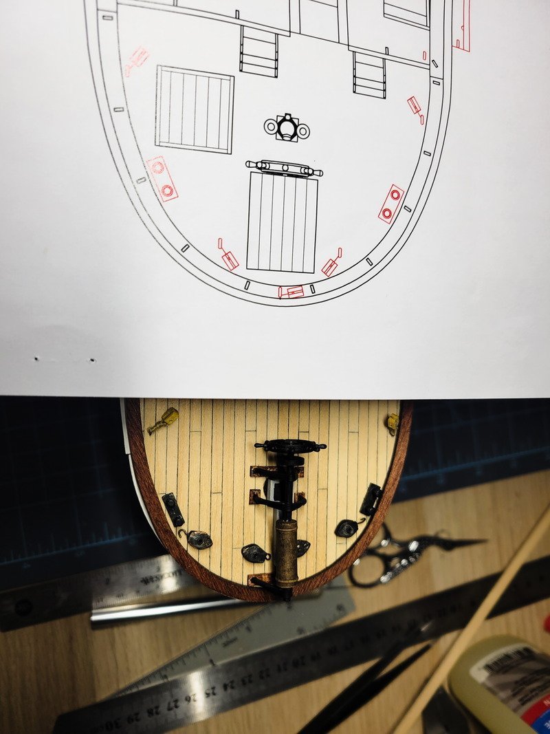
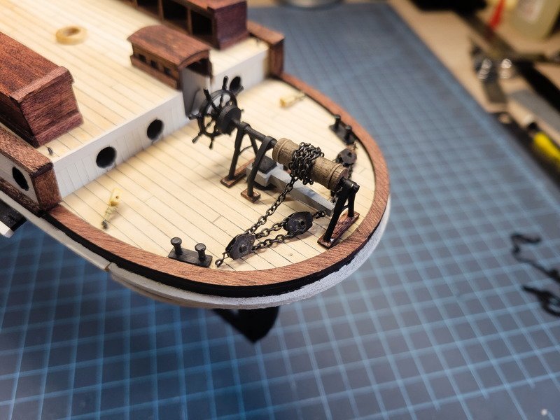
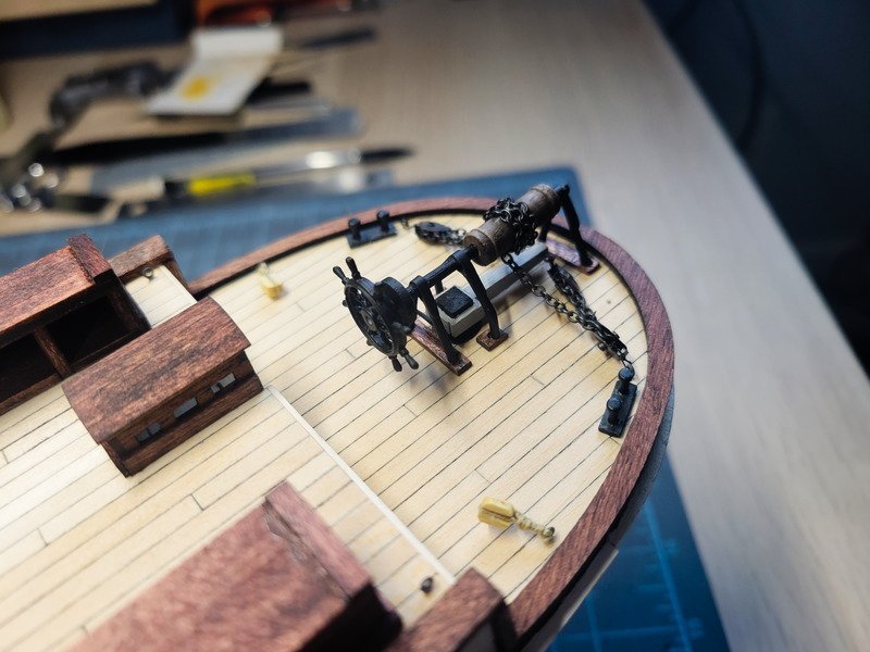
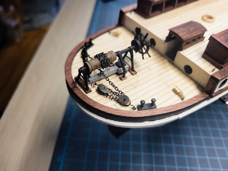
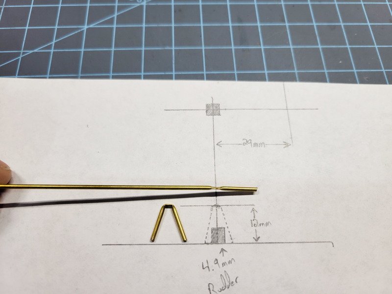
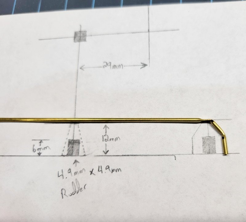
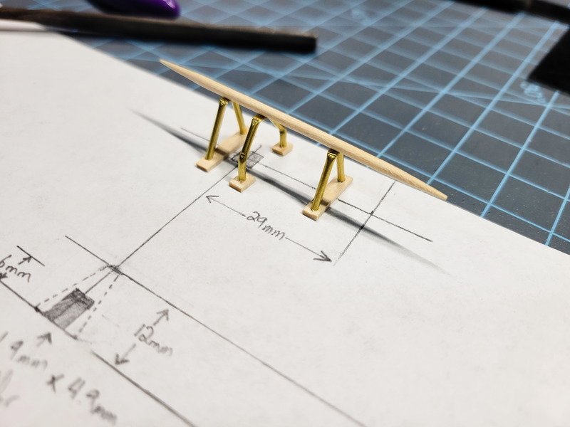
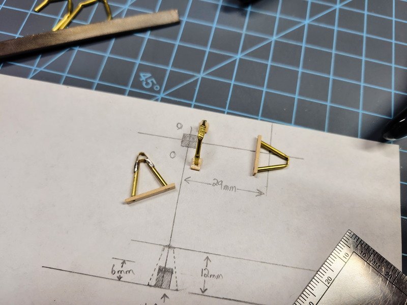
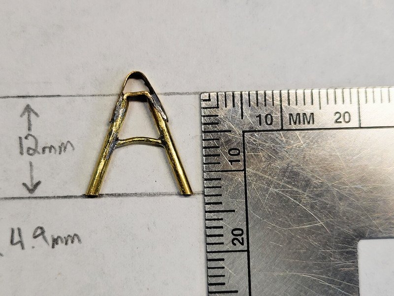
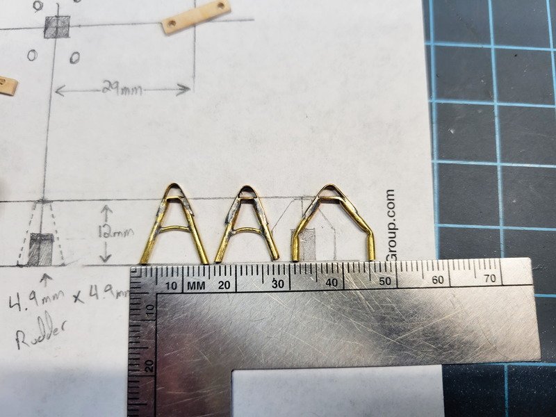
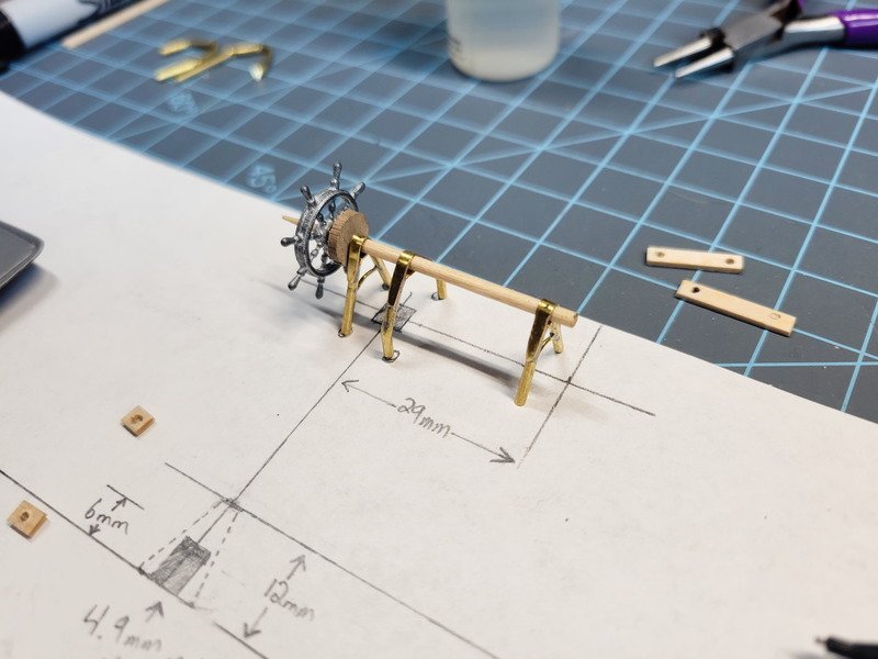
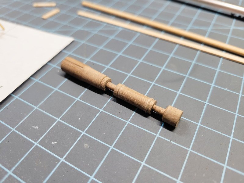
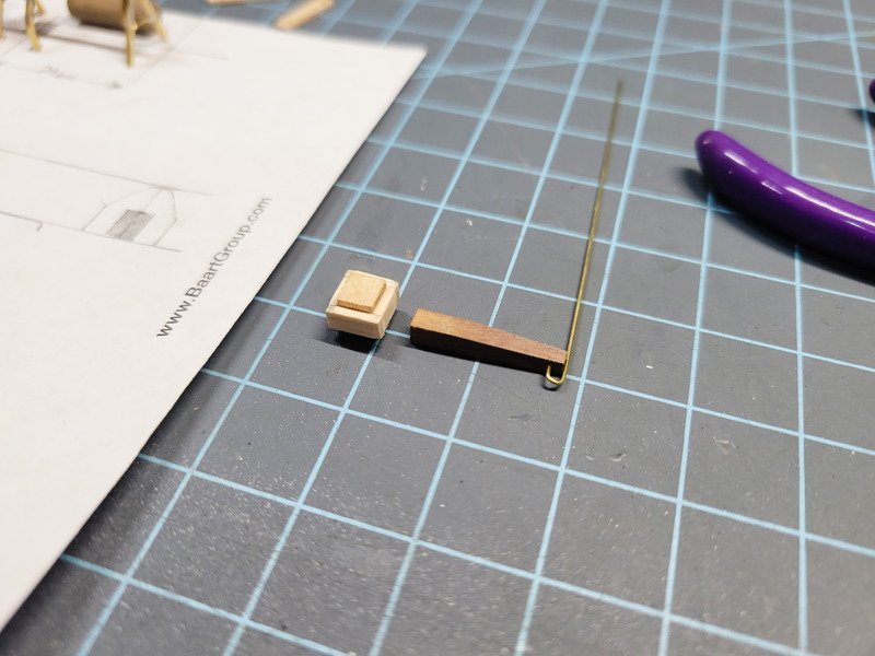
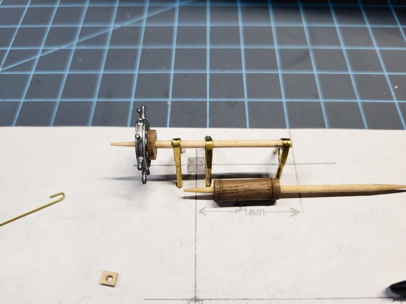
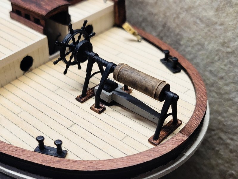
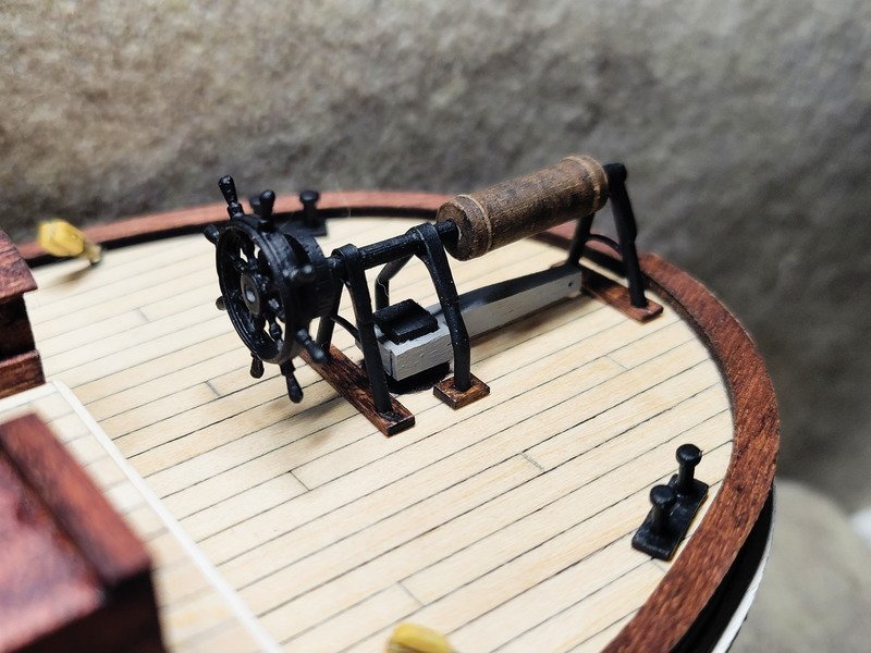
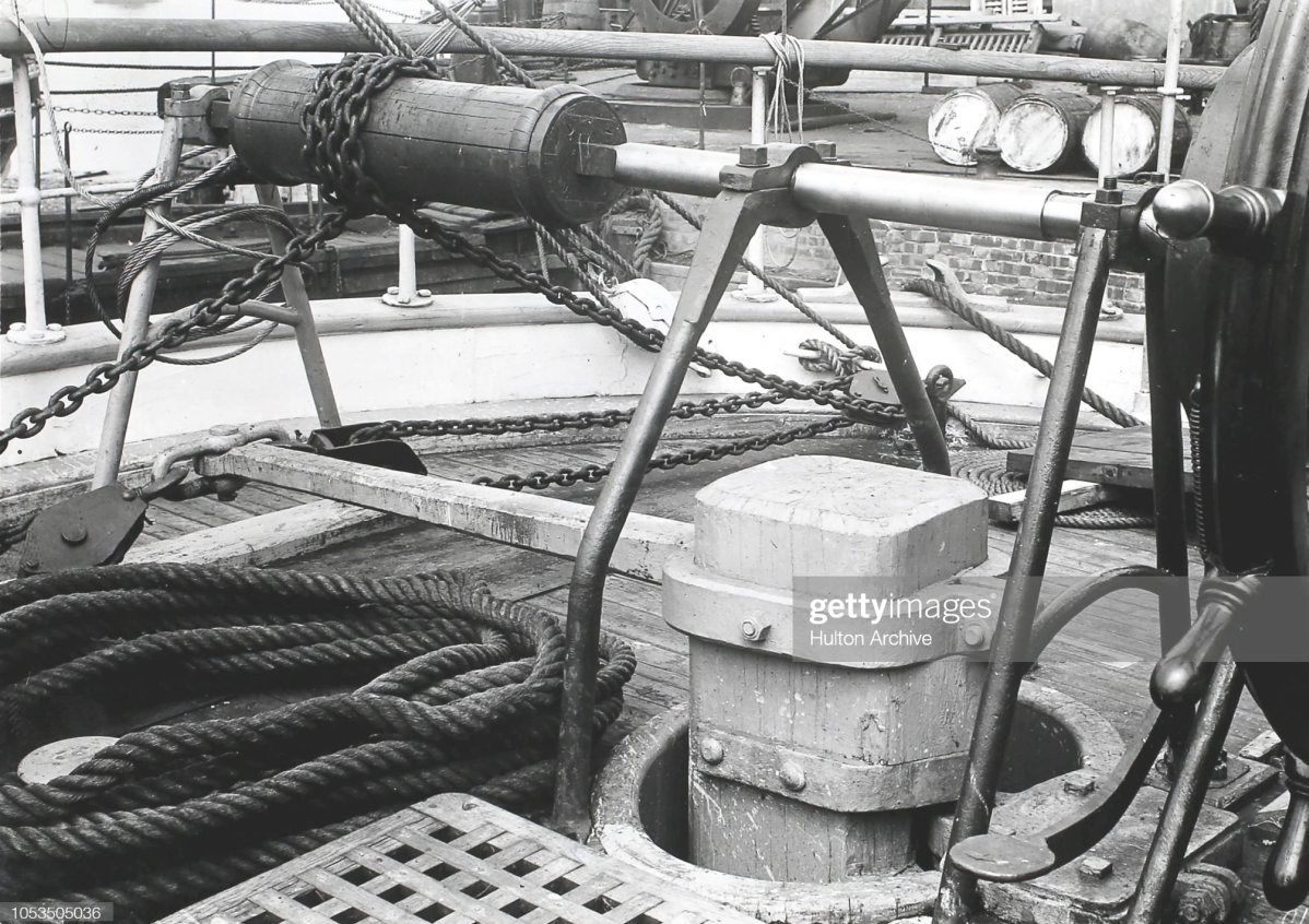
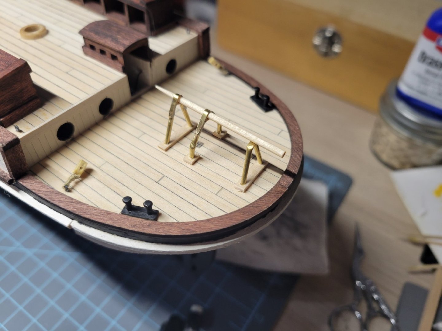
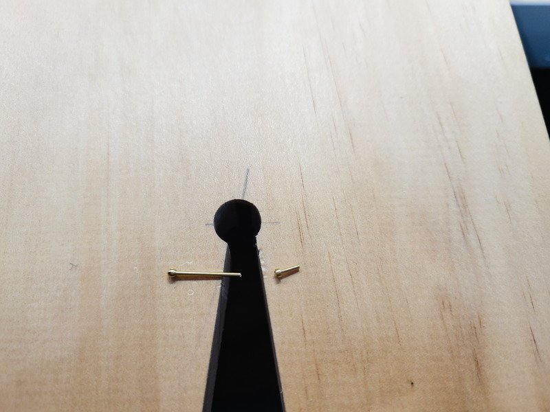
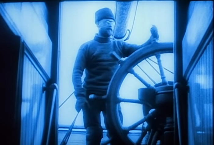
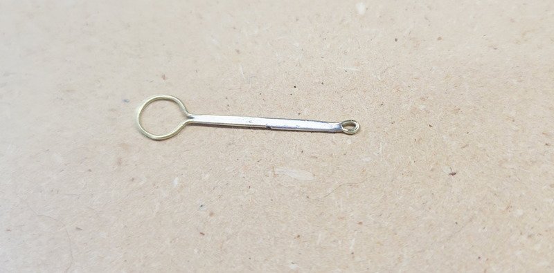
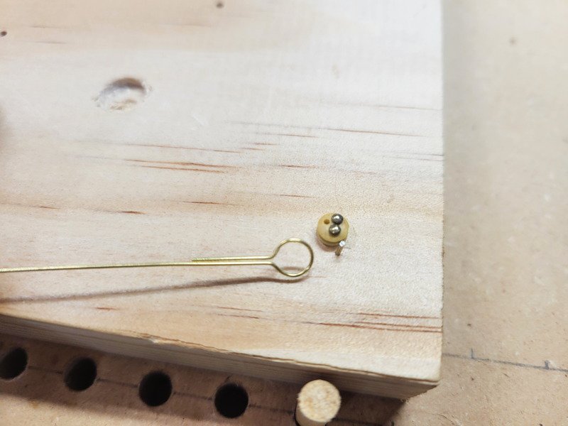
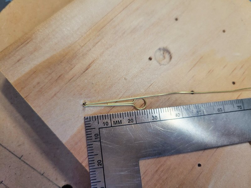
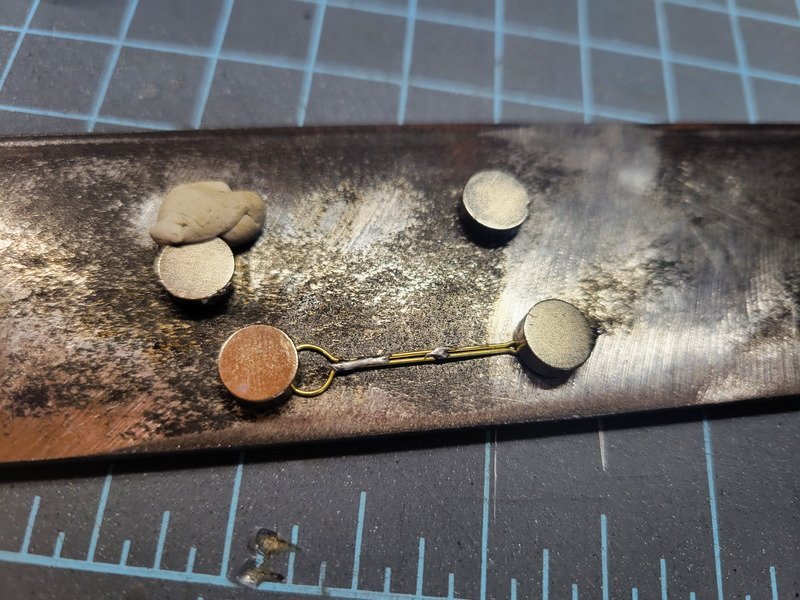
That'd be an interesting detail for sure, and I'll keep an eye out for when you get started. I'm not sure it'd be a large enough detail to warrant the effort spent to make it, but it'd be a really nice addition if it worked! Speaking of time spent, I have completed the steering gear to about 95%. This was extremely fun to build because I've never scratch-built something to this level, and I'm extremely proud of how it turned out. Total time spent to create it was around 18 hours, and I'm happy to be done! A huge shoutout to HakeZou, Clearway, and Jorez for documenting their models which provided me inspiration. Here's the reference I was going from: I started by measuring the wheel from the center to about 2mm passed the tip of a handle, which gives me 12mm. This was the basis of the entire planning process. Using 1.5mm brass tube (not rod, important later) I flattened a 3mm section and bent according to the drawing. Knowing I needed to end up at 12mm height, and using a "rudder" that's 4.9mm x 4.9mm (6mm high, not on the drawing yet), I could draw the angle and length and not have to measure anything. Two legs were created this way. The same process was done with the middle set of legs, which bow out a bit. Leftover decking was used as bases. The top drawing is a top-down view to help align the legs, and the 29mm is the distance from the aft deck cap rail to where I determined the position (rather scientifically) where the rudder protruded. The method? I stood back a bit and used a pencil to eyeball where the rudder would land. Place a dot, center it left/right, good enough. I spent some time thinking about what to use for the shaft and landed on a toothpick. It worked perfectly. (In the pic below, note the brass tubes in the top left of the image. The bowed leg set took 3 attempts to get the bends in the right spots.) I found out I was able to cut thin brass with a fresh xacto blade using a ruler if I do it on glass. I cut thin strips, 2mm wide, from a sheet of 0.2mm brass. It took a few minutes of constant cutting but I only needed 3 of them. If anyone has any ideas on cutting thin strips of brass I'm all ears. I know there are PE shears that exist, maybe that'd be better. I tried cutting a straight line with a bench pin but it's still not 100% straight. The soldering was done on my steel strip with magnets. Each leg set got 4 connections, then filed down. The two straight V pieces need a curved bit in the middle of them, and I wasn't planning on trying to include it because I was already intimidated enough with the overall task. I decided to go for it anyway and I'm elated that I did. I took a small rotary engraver and cut a tiny hole on the inside of each leg, directly in the center of the tube. 0.7mm brass rod was bent and then installed. I put a piece of the same 0.7mm wire under the new piece during soldering so as to make sure it doesn't sag down and get crooked. This is one of my favorite details because it's directly centered to each leg. The piece was then filed. The legs on the right in the pic above had depressions on the outside because it's tube and not rod. Maybe using a small peg to make the bend instead of the round bending pliers those depressions could be avoided. In any case, I dabbed a bit of solder on the top of both and spent time filing back to a curved surface. I think the effort was well worth it, as otherwise it would've been quite obvious. In the grand scheme of the ship, there's no reason to worry about that. But when I started this model one of my goals was to practice metalworking in some form or fashion. I saw the steering gear as the perfect opportunity to do just that. The brake is made from a small sliver of 8mm walnut dowel. I took the same 8mm walnut to the lathe and came back with this: This is when I learned my tools are way, way too big for a job like this. Are there mini gouges out there? I saw a guy use an old screwdriver that he ground to some sort of shape and it was perfect for scale stuff. I have a bench grinder, and I have an old screwdriver...but I don't know what the shape needs to be. I'll have to look more into the tooling. Back on track, the barrel is 6mm in diameter and I originally measured 14mm long according to my plan view. Because I didn't measure twice, the piece ended up ~17mm long and I was set not to attempt it again using huge tools. I'll make it work! The barrel was drilled to 2mm (for the toothpick) and wiped with tung oil. Now for the tiller, 3x3 walnut was tapered and drilled for 0.5mm brass rod to be the chain attachment point. The 4.9mm square rudder (6mm height) was trimmed in the same decking material to be the tiller band. Ok, almost done! I glued the two sets of legs on the left and realized I was running out of room in the aft for the barrel. I ended up cutting the toothpick in the middle of the barrel after paint, and inserting each end. It's snug enough it doesn't need glue and I'm able to telescope each side in or out to get the perfect length. The mistake ended up working out anyway. A few things to note: the wheel is not glued because I am probably going to paint it, but it should be closer to the brake. The real ship had a 10-spoke wheel and the kit provides an 8, so I need to decide if I care enough to replace it or not. Honestly, probably not. I also see the assembly needs to be elongated a touch, which can be done since it's not glued down and not connected in the middle of the chain barrel. I'll extend the aft legs all the way to the caprail, which will give more room to the chain connection point. The barrel received some black wash for weathering, then I sanded as lightly as I could the two raised bands for contrast. Last but not least is the rudder tiller. I shuddered to think about drilling through the deck (flashbacks to under the f'csle ... ) so I decided sharpie would fake it nicely. I was right, because my wife came over and thought there was a hole there the entire time. I said it was just sharpie and she had to get really close to make sure lol. I drilled a small pilot hole in the center of the sharpie circle to insert a brass nail and clipped off the head. Drilling a hole into the bottom of the rudder allows me to just stick it on without glue or anything. It even turns!! Thanks for reading this far!
- 227 replies
-
- 10
-

-

-
It's not something I'd considered but could give it a shot. I do want a messy deck as if it's being lived and worked in. Do you have any suggestions on how to achieve the effect? I'm thinking something to wrap around the rail that's really fine but frayed, like a thin fabric. I'll look more into it!
-
Thanks for the comments everyone! I'm leaning towards steel cable being used because of the kinks that are shown and can explore the thin fishing leaders, thanks for the suggestion! I think the easiest solution might be to make some thin scale rope with white thread and lay it up as tight as it'll go. I'm thinking the cable would have been painted at one time, so white would work. There are two eyebolts on the caprail where the railing thread terminates and I could seize them with black thread for some interesting contrast. That sounds better than using the 0.7mm brass rod, and I wouldn't need to hunt for fishing leads. However, I've seen discussion in other Endurance threads that the shrouds were steel braided cable and I'm wondering if they could be reproduced using the fishing lead. I used to be able to splice an eye in steel braided cable and it's not very difficult, so can the same be done to fishing lead at scale? After my update earlier I got back to work and decided to attempt something for the steering gear. Here's a teaser pic of progress, I'll have a proper update with lots of pics tomorrow.
-
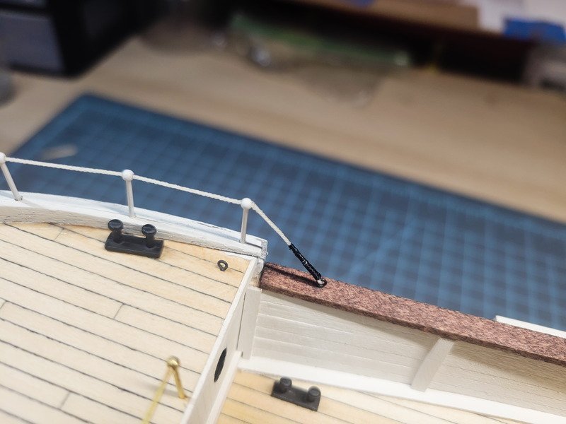
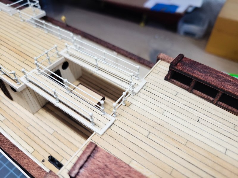
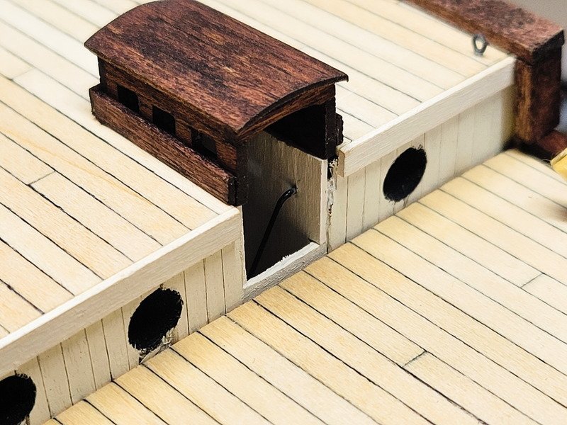
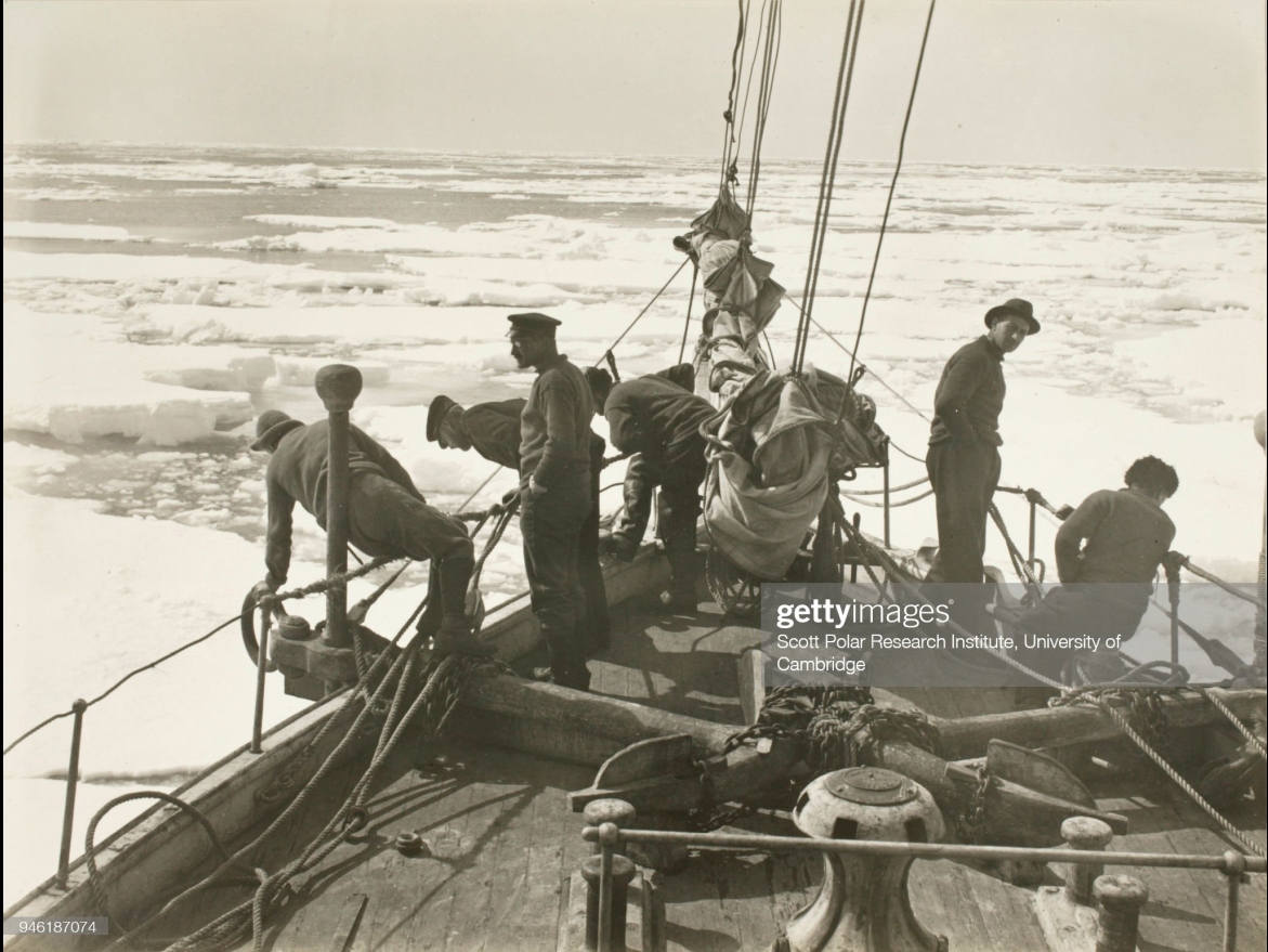
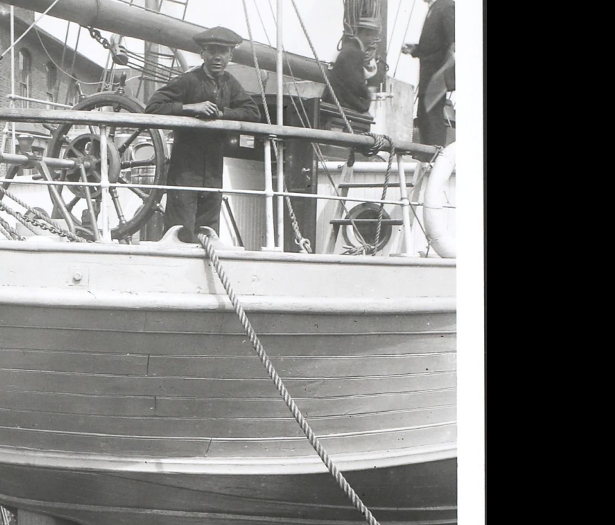
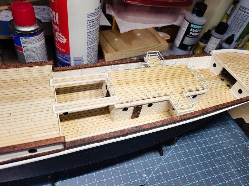
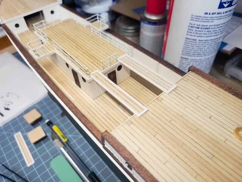
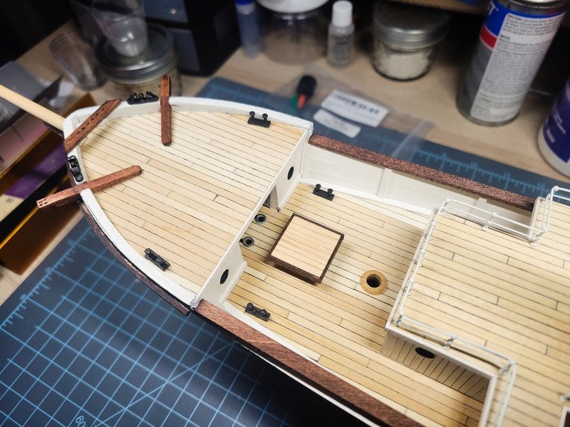
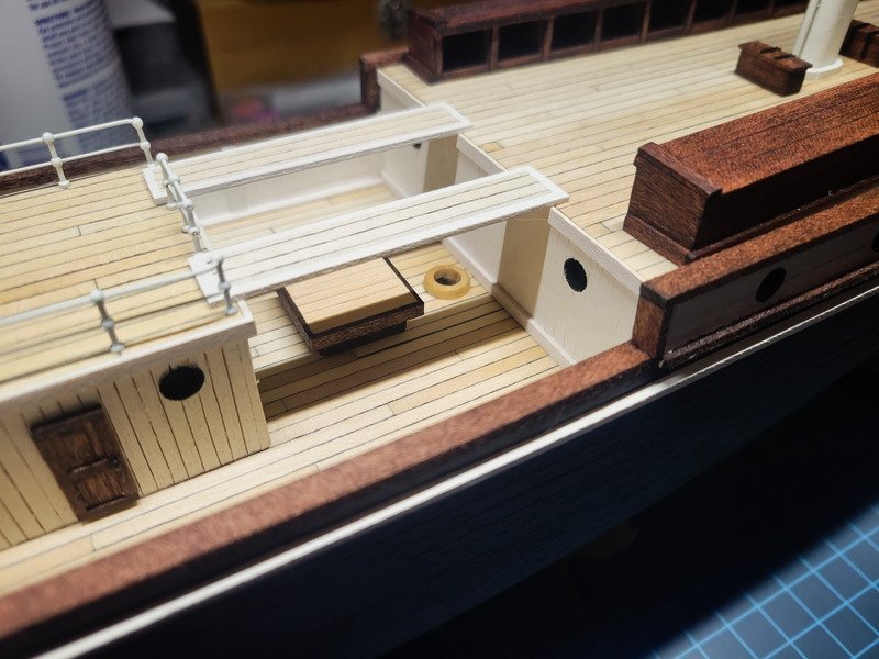
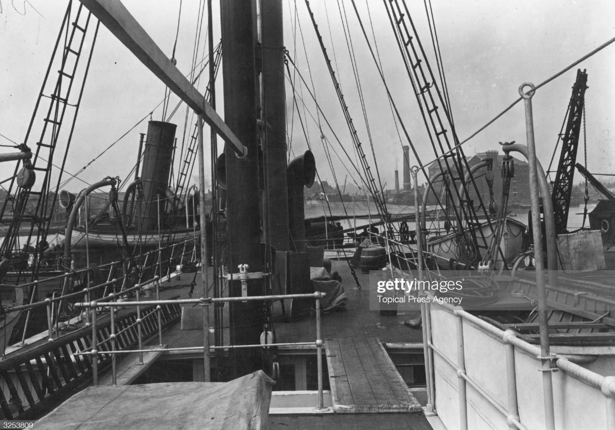
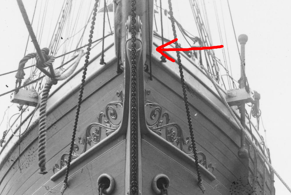
Hi everyone, a quick question before I update progress. Take a look at this bow pic: I've made steps toward installing the bow railing and am wondering what to use through the stanchion balls. For the aft part of the anchor deck I can see in the pic above it's metal, so I used brass wire for that railing portion. The rest of them look like they have a rope or steel braided cable running through them. My question is, what color would the rope be? Or rather, what should I use? I could either use brass wire which matches all the other stanchions on the ship, or a scale rope. If I used wire it'd be white to match. However if I go the scale rope route, should it be tan or white? Black? The wire would match, and so I'm leaning towards that route the more I think of it. I can just imagine friends and family over the years asking why the bow stanchions don't have a wire rail but all the others do. This is a situation where artistic interpretation may override historical accuracy, but I'm curious what others think. The 1-ball stanchions needed to be cut down because I couldn't find any 12mm in stock anywhere. A bench pin and a jeweler's saw made very fast work of it. I also get to keep the little cut offs to be used adding details elsewhere. Don't mind the solder in the next pic, I need to file it down still. I wasn't able to use the drill press to drill the stanchion holes and I can't seem to understand how to use a pin-vise while keeping it straight up and down. They'll get adjusted once they're glued down. I also finished up the gangways for the bridge deck, and applied the first railing to the mizzen deck (not glued down!) The stanchions needed to be ground down using a bench grinder otherwise they stuck out from the bottom of the planks. The gangways could be 1 or 2mm wider, but I'm not going to make them again (as these are the second sets anyway). They can be removed of course, which will make it really nice during the rigging stage. In fact, I thought of an idea of posing the crane with a gangway in the hook, hanging down and on it's way for installation. My wife wasn't so sure, but when the time comes maybe I'll revisit that. It'll depend on how she's displayed as I haven't decided what the rigging configuration will be. The shroud channels were glued on. The fore skylight is looking awesome, but don't worry it's not glued! And then the aft companionway received its handrail, the companionway glued down, and some trim stained and added. The drydock pics show a handrail on the port side of the companionway (on the inside), and I doubt it makes sense to have a rail on both sides. So yes, the handrail on the starboard wall is not accurate. Artistic interpretation takes hold again. The port side is being displayed, and the viewer would never see it if I put it on the port wall. To give someone an idea of the forethought that went into this though, I chose the starboard side as the display side specifically because I saw the rail on the port wall. Not everything can work out though and adjustments can be made when need be. Edit 9/19: Turns out there actually is a rail on both sides as seen in this video.
-
Hey Keith, your Endurance is beautiful and it'll be really cool to see without paint. I know you're busy with Erebus, but when you come back to Endurance, what do you plan on using for the bow stanchion railings? Will you use brass wire, as done with the other rails, or use thread? I'm trying to figure out what I want to do, but am leaning towards using brass wire and painting white even though it's not 100% accurate.
-
Thanks for the tip Jack, I'll give it a try when I make more. As for getting the deadeyes to fit tightly the short answer is...they don't. Before soldering I made sure the strops can fit on to the deadeyes with a bit of coaxing. I'd say they're loosely fit in the strop, but they do stay there once they slip in. But it's not as tight as they could be either. Once tension is there with the shrouds, it shouldn't be noticeable. If it is, I can still squeeze the loop around the deadeye to shape it better.
-
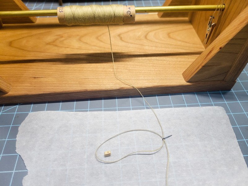
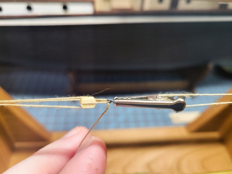
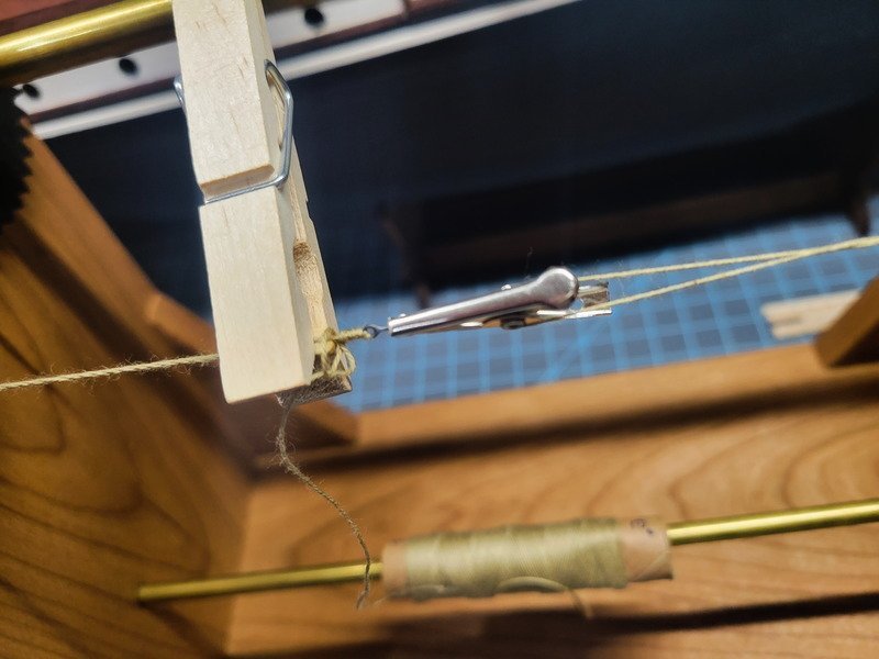
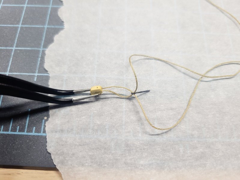
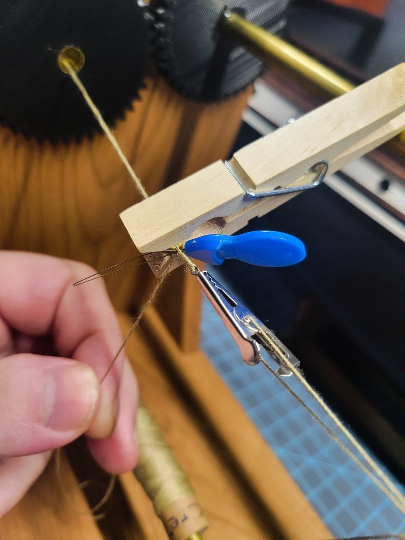
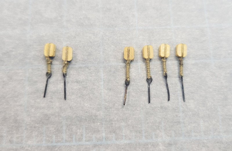
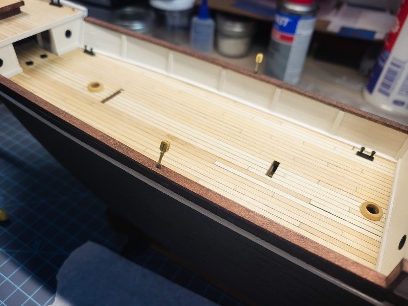
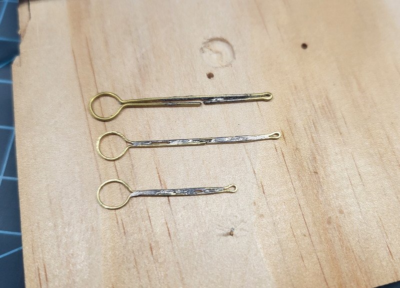
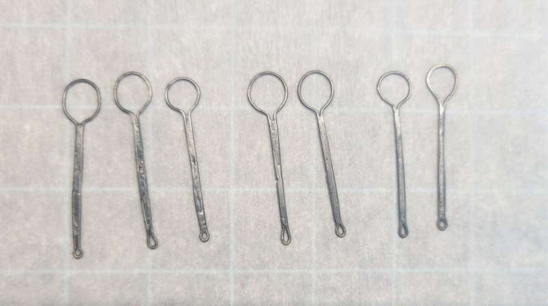
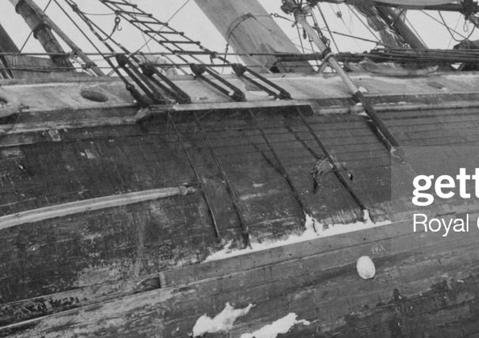
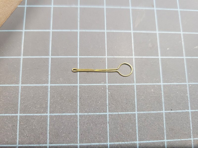
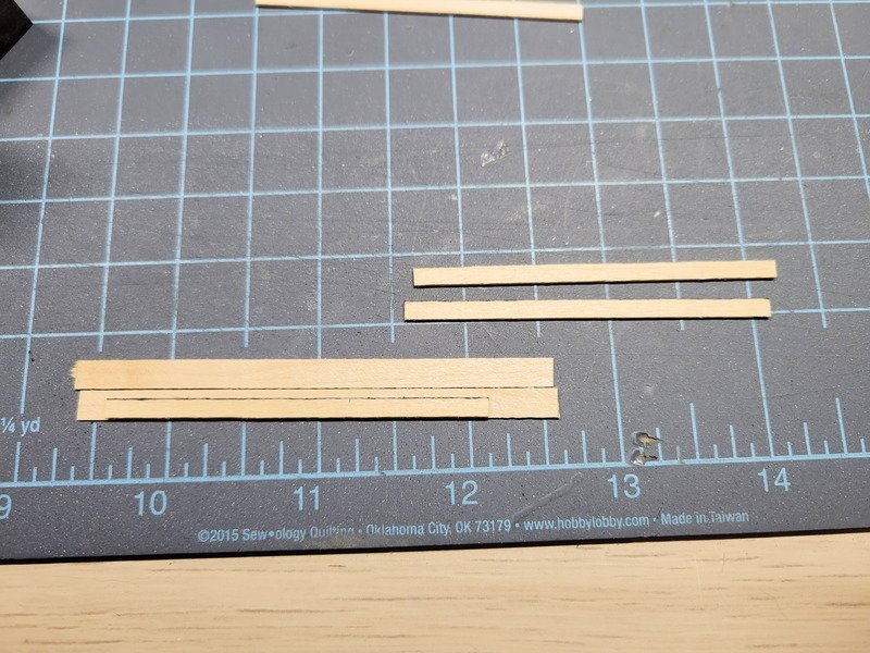
Hi folks, thanks for the likes and following along. Another big picture update for this post, as I wanted to show the technique I'm using to seize blocks and also create chainplates. These two tasks have taken a lot of time, but I'm so happy with the results I believe it to be worth it. I also find it oddly cathartic to drone away while listening to movies in the background, so it's not so bad. Let's start with seizing blocks. Back on page 1 of this log I mentioned building a seizing machine, and boy it really came in handy. First step was dragging the end of the thread through some CA and wiping off with a towel. This gives me a needle, without needing a needle. I thread it through an eyebolt (a reminder that all eyebolts are soldered and blackened, so they're completely closed) in one direction and then go back through the same way, leaving a loop. Using a drop of CA I glue the thread to the sides of the block. I make sure the rigging hole is oriented towards the eyebolt. The thread is pulled taught until the eyebolt is in the general area it needs to be. I'm shooting for the block to be one-block's distance away from the eyebolt. On the left side of the machine I've attached a single thread with a CA glue needle. This gets threaded through the hole in the block. The right side has an alligator clip which holds the eyebolt. The loose end from the spool (which is through the eyebolt) gets run through the left side and fixed to the pegs. This part is a bit finicky, and it's not super repeatable. Everything needs a certain tension to look good at the end, and the thread needs run through the eyebolt and lie on the block a certain way. Practice definitely helped here. The machine handle is rotated and the tension is held on the thread coming from the spool until I see rotation begin to happen with the block and eyebolt. I can start letting the spool out, which rotates the block and eyebolt more, all while keeping things tight. It's hard to explain, but after my second one I was able to reproduce the result I'm looking for. Once the thread from the spool has been wound up to the base of the block, I clip on a clothes pin to stop rotations and insert a needle threader at the base. I'll cut the thread from the spool, leaving around 3-4" so I can pull it with the needle threader through the gap at the base. Before pulling all the way through I bring the loose end through the loop that's created, creating a single overhand knot. There are three threads running through the left side of the machine, so I grab the thread attached to the block (not the thread running through it), release it from the pegs and bring it back to the middle. I'll cut both loose ends, and apply a drop of fray-stop on both sides. The two on the left in the following pic are the first two I made. The next 4 I had figured out the correct way to lay the threads, the correct winding tension, and a better knot to complete everything. The furthest on the right just came off the machine and has fray-stop at the base of the block. Once it's dry it'll be the same color. And there we are installed. I left off the 3 furthest aft as I want to build steering gear and make sure everything fits before getting attached to the hull. Does anyone think they're too tall? Should the seizing be shorter? Steps M would have you drill holes into the bulwarks rail for the foremast deadeyes. I'm not sure why OcCre decided to do that when making a channel for them would be just as easy. I fabricated them from 2x5 hull planks and then started considering chainplates. The plans call for brown thread, but I wanted to attempt to upscale this detail by creating them from brass. Here's a photo that shows them pretty well. Since this post is already getting long with several more pics to go I won't detail the amount of times I failed to solder something I'd want to use on the ship. However in those failures I learned how to get better with each one, and now I have some truly stellar pieces (in my opinion) to use. And what's weird, I'm excited to get back to the bench and make more! Alright so to start I made a small jig by just nailing the two sizes of deadeyes to a flat board. The deadeyes are really out of scale, but I decided I'm not interested in changing their size by buying aftermarket. I looked into making them but don't want to put the effort into it. I'm pretty sure I'll stain them though. I started with the foremast, and according to the plans the thread should be nailed 30mm below the deadeyes. Since I'm going to be using a channel on the white trim stripe, just like the other two masts, I noted the deadeyes will have moved down 10mm from their previous position. This means I'll want 20mm between the bottom of the deadeye and the nail, because I don't want to change the position of the nails. This works out because the main mast has a distance of 23mm, and the mizzen mast has a distance of 20mm. With that said, I start by marking 10mm on a length of 0.5mm brass rod. I begin the bend around the deadeye there, and using the headless nail and pliers I aim for the shape in the pic above. I mark out 20mm below the deadeye and use another headless nail to make the bend. After cutting the excess, considerable time is spent using pliers and magnification to make it as straight and tight as possible. It also needs to lay as flat as possible. I use a piece of steel flat bar as a building surface with magnets. The magnets and putty are used to hold the chainplate down. I found it's best to get the shape as close as possible and not rely on the magnets to shape the piece. I had one I had to throw away because during filing it sprung apart. With the solder all over it it's just faster to make a new one. In the pic above I was more focused on "tacking" so I could remove some magnets and have more room with the iron. The iron is, well, ferrous so the magnets will attract it if I got too close. That was really annoying to find out the hard way. This was when it hit me it's better to spend more time getting it to lay correct on its own rather than force the shape with magnets. Then, only 2 magnets are needed to hold the piece and the entire length can be soldered at one time. I use a liquid flux first, then put solder on the tip of the iron and apply. Pic above: The top attempt is 30mm from bottom of deadeye to nail and is made with 0.7mm brass rod. I don't know why I thought it needed to be 0.7, but it's way too big. I also wasn't able to successfully solder it. The 0.5mm rod was much easier to manipulate and shape, and looks more to scale. The middle attempt is also 30mm, and I started figuring stuff out so that's when I actually measured for the correct distance. The first two were just practice to see if I could do it. The bottom attempt is almost passable, and will probably be used on the non-display side since they take so long to fabricate. With practice things get better, though. Here was my final attempt (for now, I'm actually going to post this and go make more! I find it really fun.) When each piece was complete I used steel wool to shine them up and they got placed in a small plastic shot glass of hydrochloric acid until I had 4 large and 3 small complete. They all got washed off in water, then processed in brass black two times. The final step was to rub each side with paper towel, buffing them up. The progression goes from left to right, and I'm pleased to see my technique improved with each iteration. As mentioned I'll still use the "not-so-good" ones but they'll be on the non-display side. There's a bright LED light directly over them so they appear very shiny/silver in the pic. In real life, though, they're a deeper, darker color which I find extremely pleasing against the black hull. Phew, this is a super long post for two tiny details. I hope this is helpful for anyone to help create these things! Thanks for reading!
-
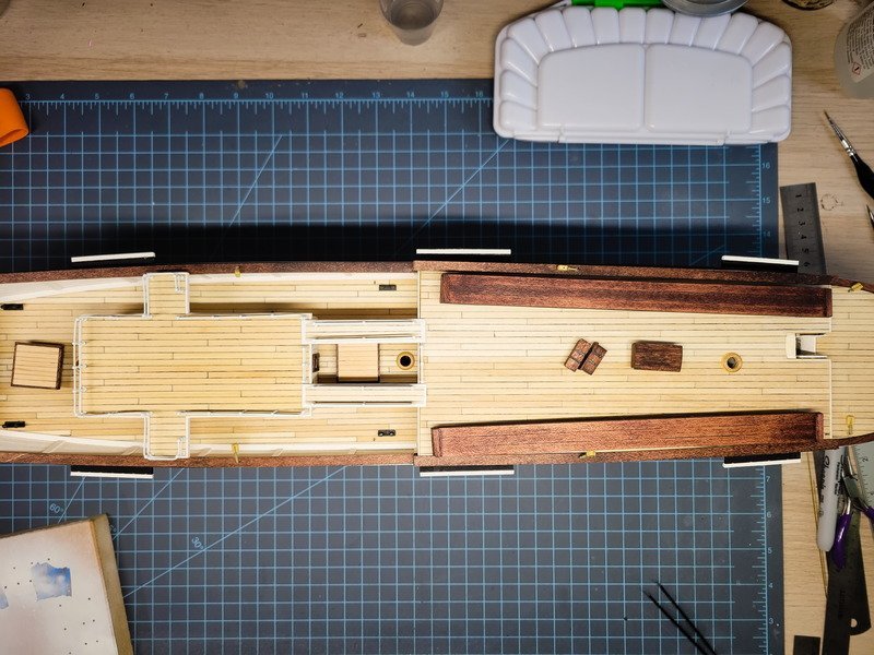
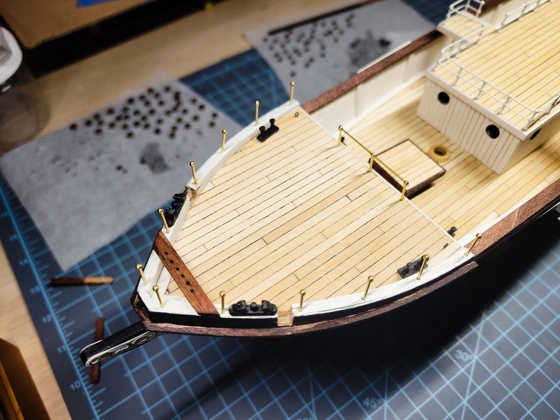
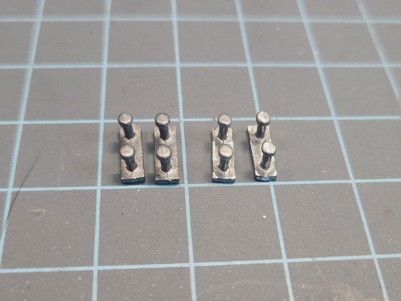
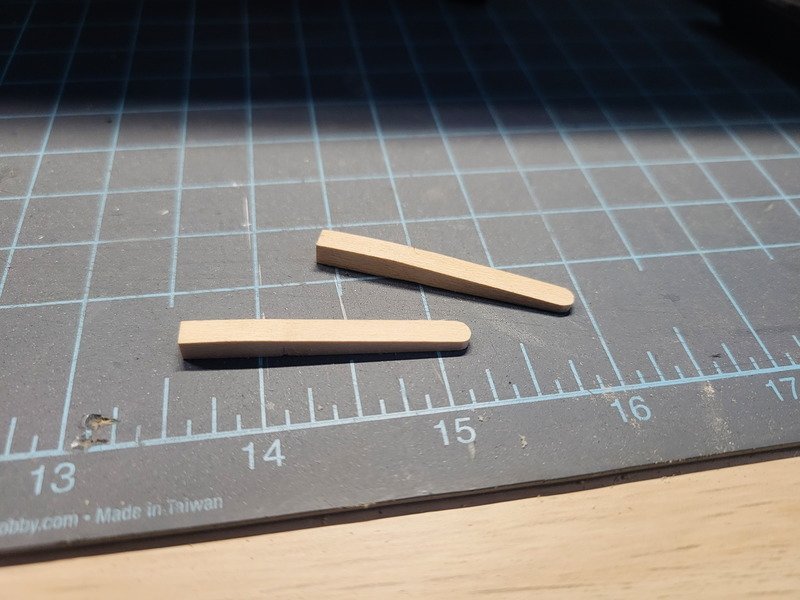
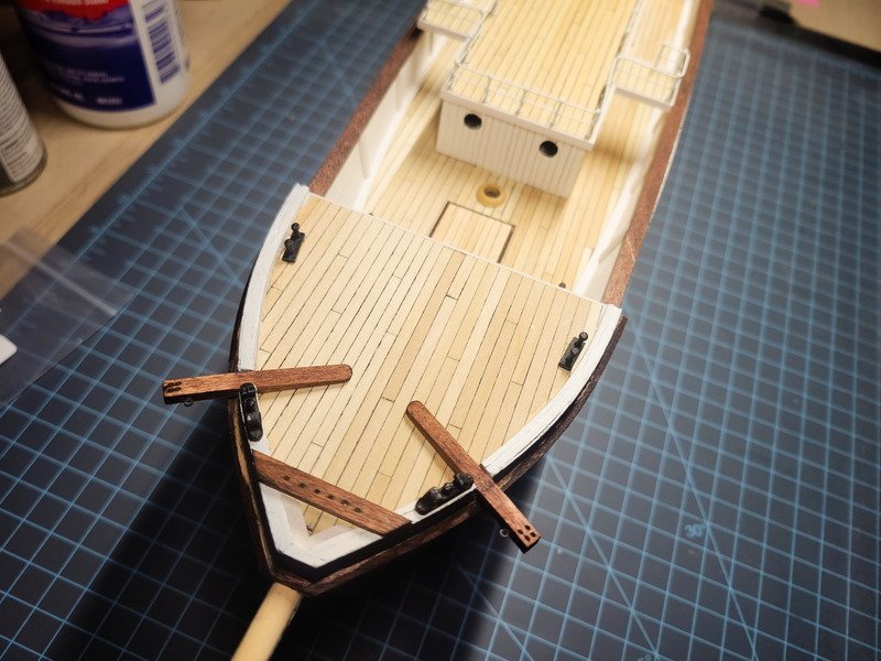
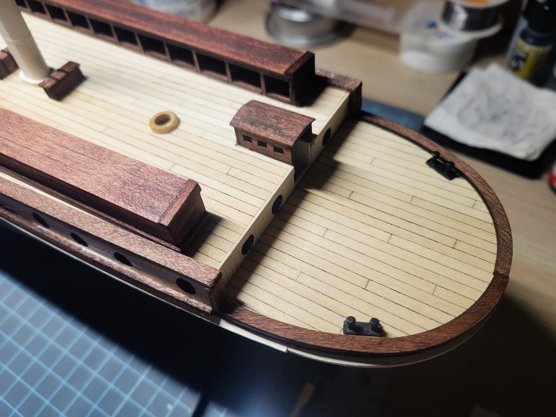
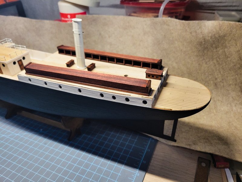
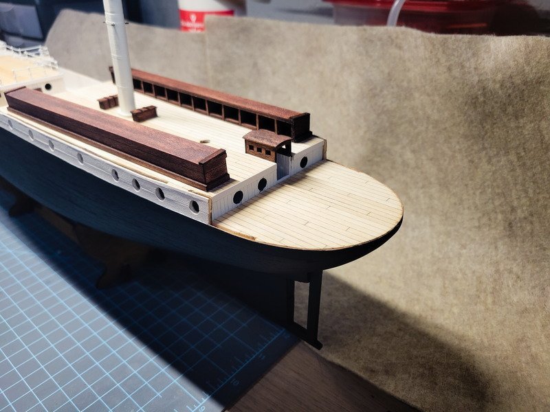
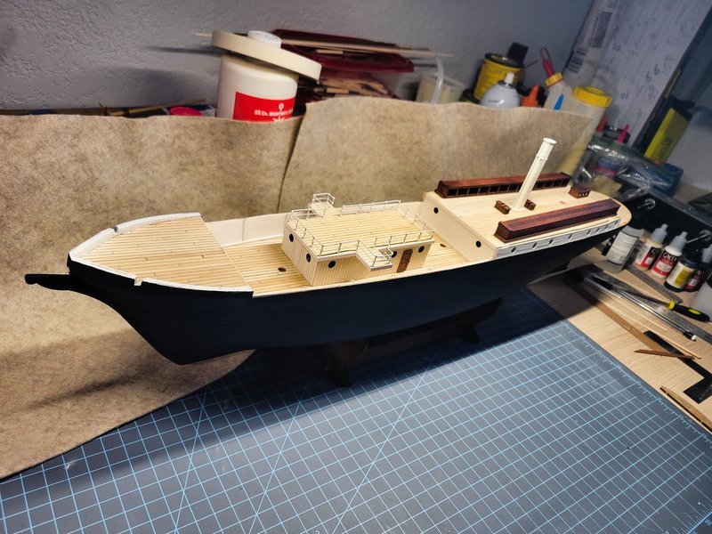
Thank you for the likes and comments everyone. I have a big picture update, so I'll get right to it. I did end up forgetting a step a few pages ago, so I cut and installed the two angled pieces at the bow. Next up I used some needle files to clean up the bollards. The filed versions are on the right. They received paint and were left to dry. In the meantime I wanted to begin addressing the gangways from the bridge to the mizzen deck. Here's the reference pic I'm modeling from. I started with the same 1x3 I used for the deck, with sharpie to simulate caulking. Because I already installed the stanchions, I could only fit 3 planks between. I thought the 1x3 was just a bit too thin, so I added some 0.6 veneer for thickness. After painting the white borders, they're complete. I'll need to drill them and install stanchions at some point as well. I started shaping the anchor davits next, which were then drilled and stained. The plans would have them touching at the aft end and not tapered, which isn't correct. They taper down to just above the deck, and I believe are rounded on the ends as well, so I did my best to depict that. As the stain dried I kept staring at the gangway widths. They're definitely not wide enough, which is what I was afraid of. No matter, I built two more using 4 planks this time instead of 3. I also removed the railing section (luckily those three didn't receive CA glue) and drilled two more holes, closer to the middle stanchion. So the gap can then accommodate a 4-plank gangway. Here's a comparison of the two: You can just barely see the previous stanchion hole under the 3-plank gangway. The 4-plank gangways cover them up. The paint glued the brass wire to the stanchions pretty well, so I had to aggressively(-ish) slide the stanchions on the wires to get them to fit in the new holes. Touch up paint was definitely needed. And finally the quarter deck skylights were completed. The only things glued down now in the following pics are the bollards, bow pin rack, and mast bases. Oh, speaking of the mast bases, they were very undersized to the masts. It took a while with a round file because I was worried they'd break if I filed too hard. They all fit like a glove now though. The kennels, chests, funnel, companionway, deck house, gangways, skylights, and anchor davits are not glued in. They won't be for quite a while, at least until the hull channels are installed, perhaps including the chains as well, we'll see. I just have things placed to remind myself of what I still have remaining! Thanks for stopping by!
-
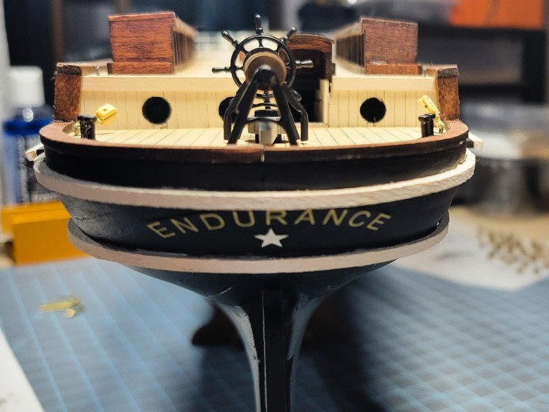
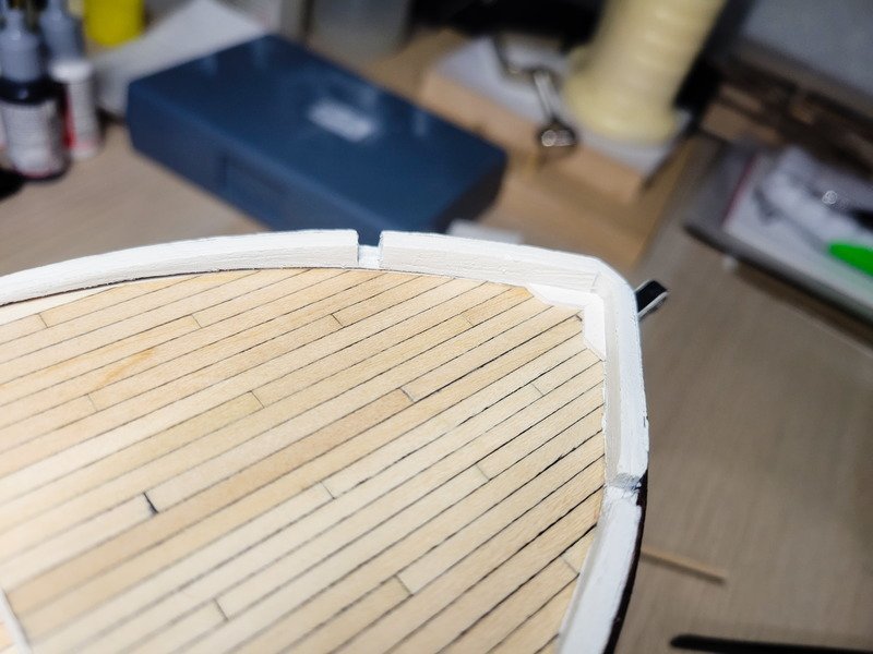
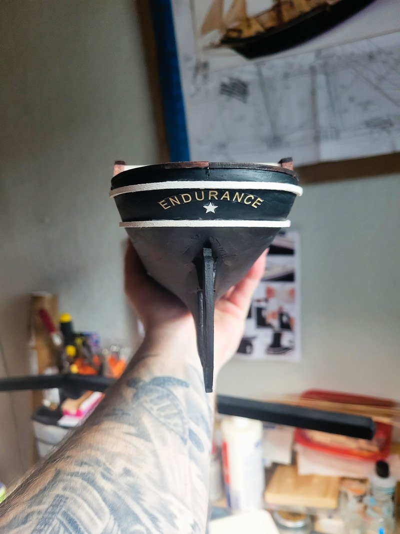
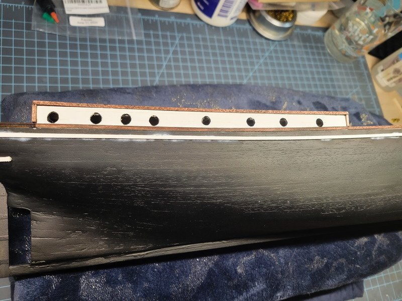
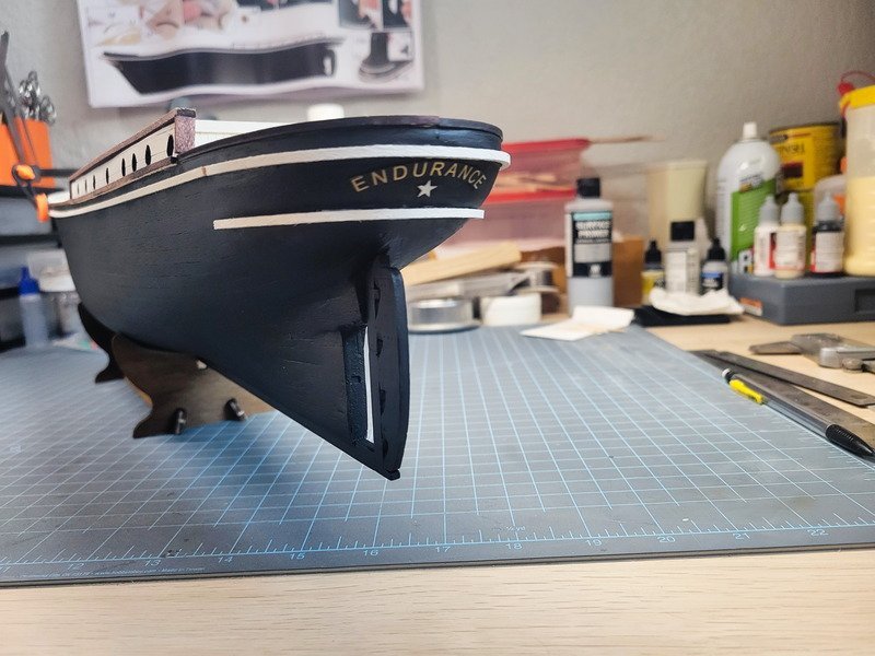
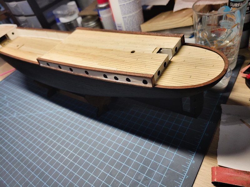
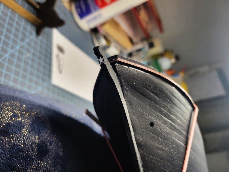
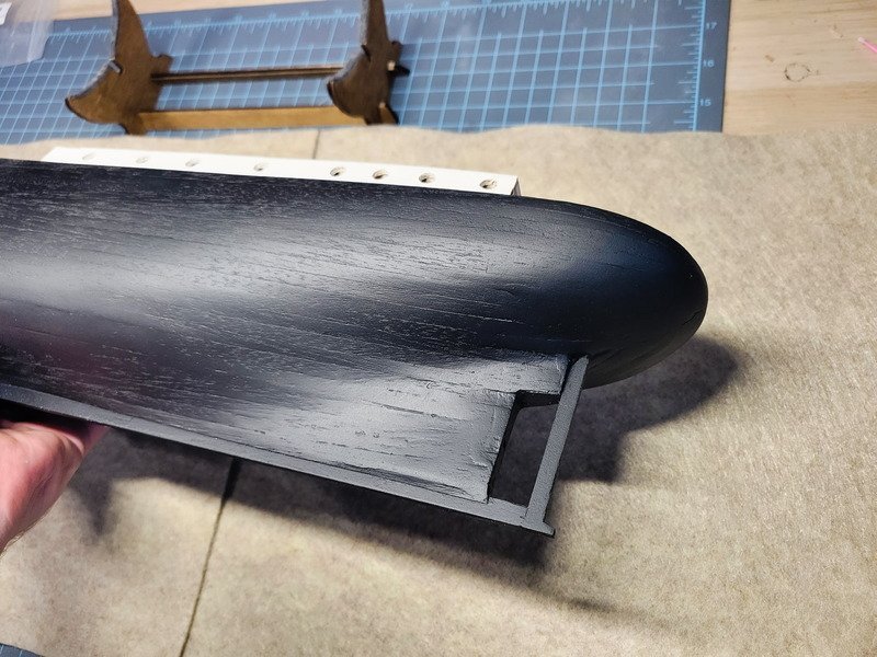
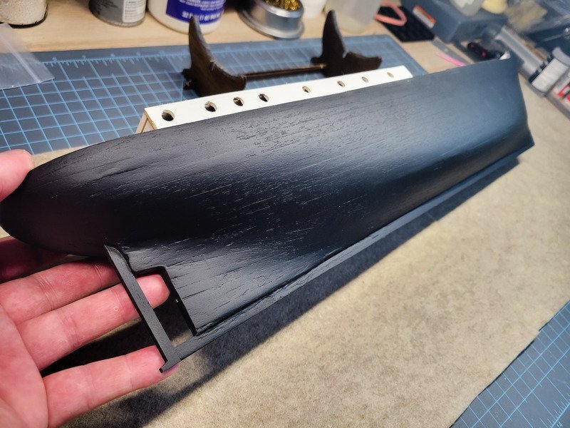
A major milestone has been complete today: the hull is 100% complete! I think, anyway. All steps up to sheet M have been complete and as far as I can tell from here on out we're on deck superstructures and fittings. Well, I still need to add deadeye channels and there's the odd step M10 that should've been installed prior to the white 2x2 strips. I glued those strips in and then remembered HakeZou brought up the fact it'd be better to install them prior to those strips. He would be correct, and as I'm typing this I'm hoping I won't need to adjust the 1x4 on step M10. The curved pieces from my previous update were the perfect shape for the stern. Just a touch of adjustment, which they kept very well, and I could glue them to the counter stern with CA. A note here, I was thinking I should bevel the strips prior to soaking and bending, but I didn't do that. Because I didn't bevel them I had the tiniest corner of the 2x2mm strip to glue to the hull. There are gaps if you look super precisely. I would suggest to future builders to bevel them, soak, then bend. I had no idea how to clamp them, so I just held it until it was firm enough to let go. The nameplate and the star were painted and installed using CA. Everything was glued with CA, and you'll see as the glue dried I got white spots from the glue. I went back and painted over it, which covered perfectly. For the record I tried using wood glue for the curved pieces first but my lack of clamping ideas led to a lack of pressure, which made the pieces really easy to pop off. CA it was. The bow PE was painted and sanded per instructions. A note about the anchor hawse holes, I'm definitely happy with their placement considering they were drilled mid-planking. They may be a few millimeters off, but that's okay. If I didn't worry about running the chains through the hull and under the anchor deck, I would have drilled them at this point right after installing the PE. Either way, they're in good spots according to me, so it worked out. In the pic above you'll see what I mean about CA glue leaving a residue as it dries. It's not where the glue was applied, but it creeps around the area for whatever reason. Once it's completely dry though, paint covers it nicely. The final task was installing and painting the brass anchor hawse hole bits and a lot of black paint. Here's where we are currently. Don't mind the clamp, I'm currently fighting a losing battle with the starboard trim piece there. This will be the 3rd time I'm gluing that specific end down. I clamp it for a time, take the clamp off, leave, and when I come back it's lifted a few millimeters. It's been a few days of this now. Super good stuff. Thanks for reading!
-
Thanks Tom, that's nice of you to say. Even with the planks out-of-scale the grain showing through is still pleasing to look at, so there's that. I think the filler you're using is going to achieve a better result because the wood glue/sawdust I concocted shrank more than I originally thought, especially in bigger/deeper cracks. So when I thought it was the "last time" I needed to apply filler, I'd come back to it when it's dry and find that it in fact needed more. With the ply bulwarks, I'm wondering if there were a way you could scribe some relief into the wood? Since the piece isn't flat anymore it'll be harder to get straight lines than if it were on the bench. But similar to the effect I used for the quarterdeck deck house in this post here. Thanks Jack, and thanks for stopping in! I definitely don't mind cutting corners a little bit if it'll save me time and the result is hidden anyway.
-
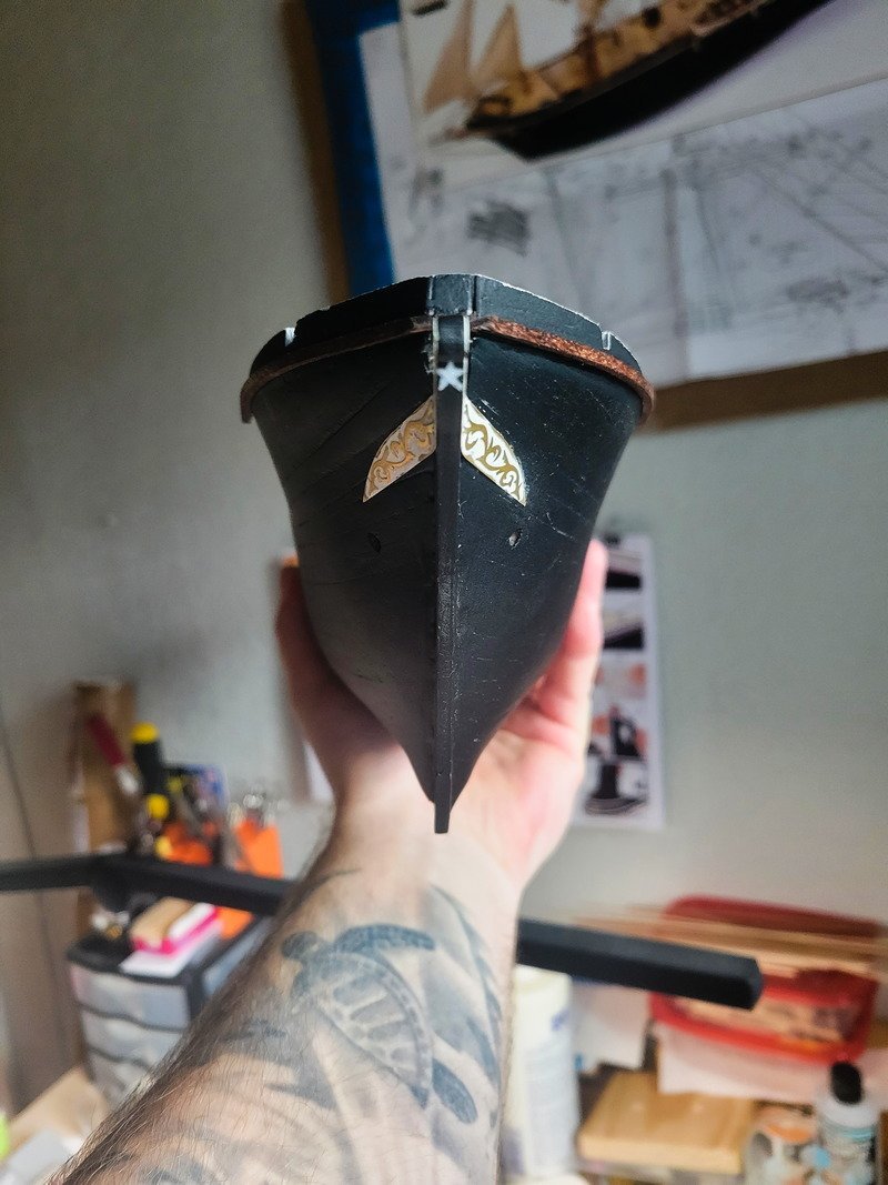
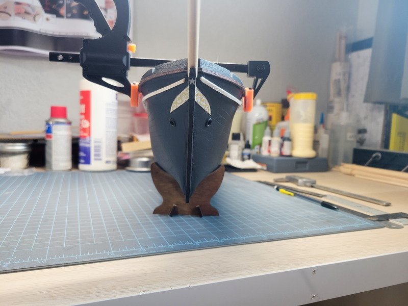
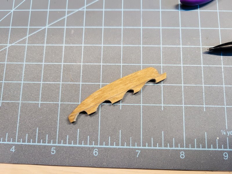
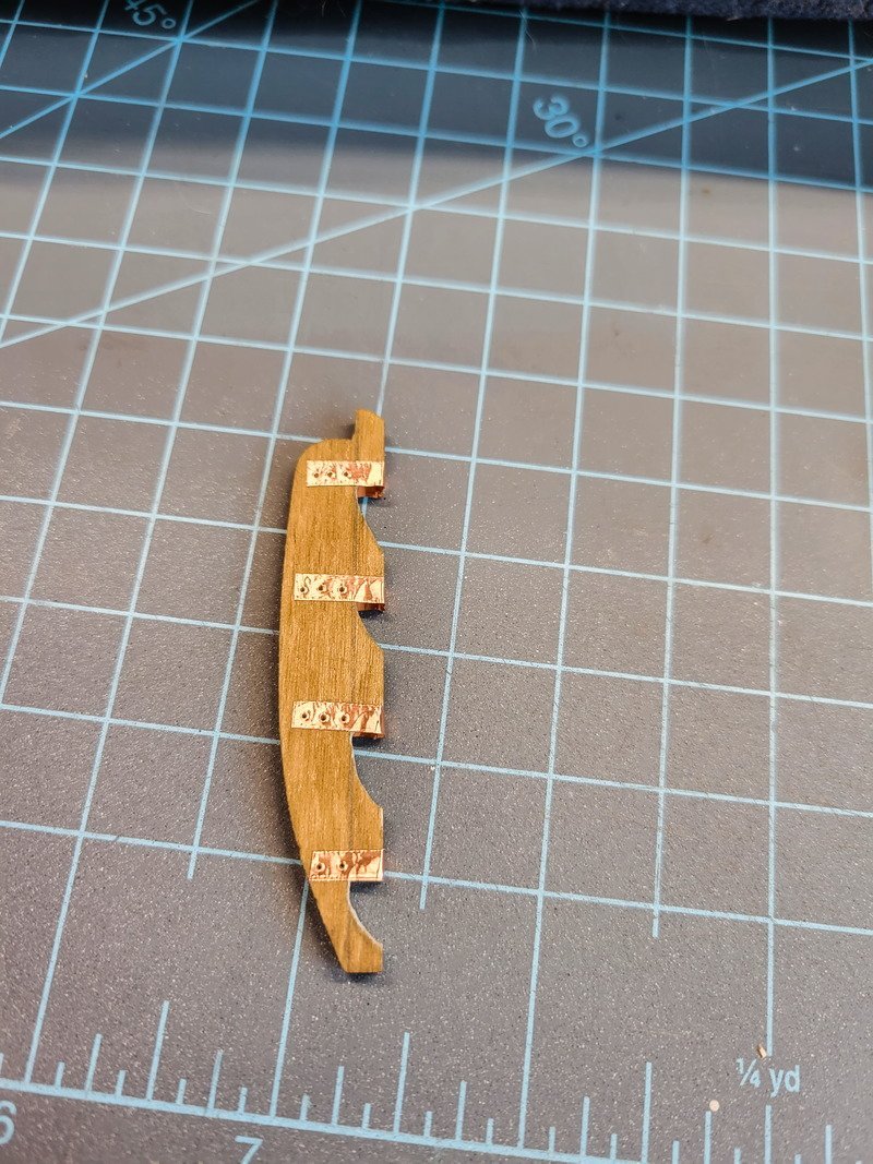
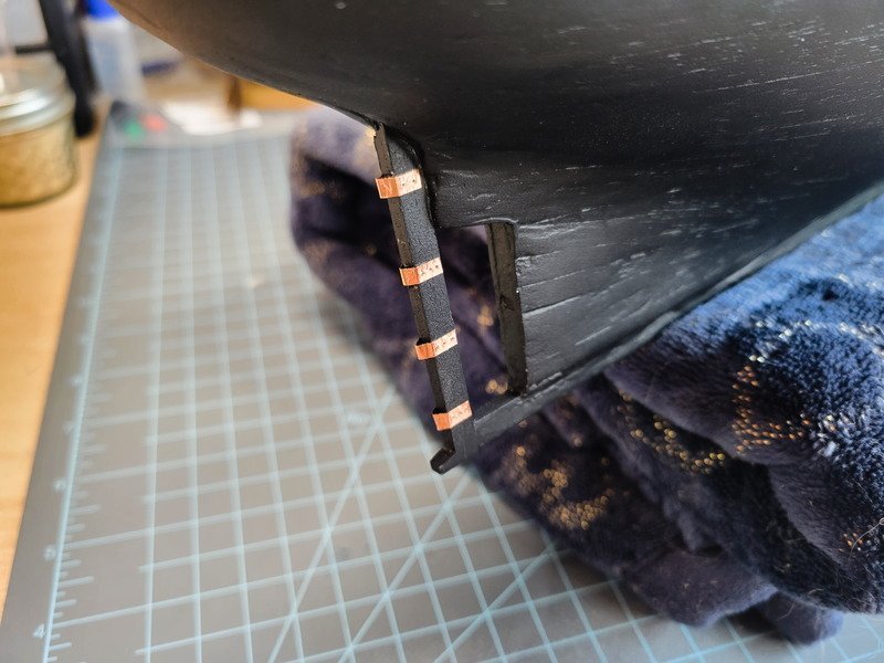
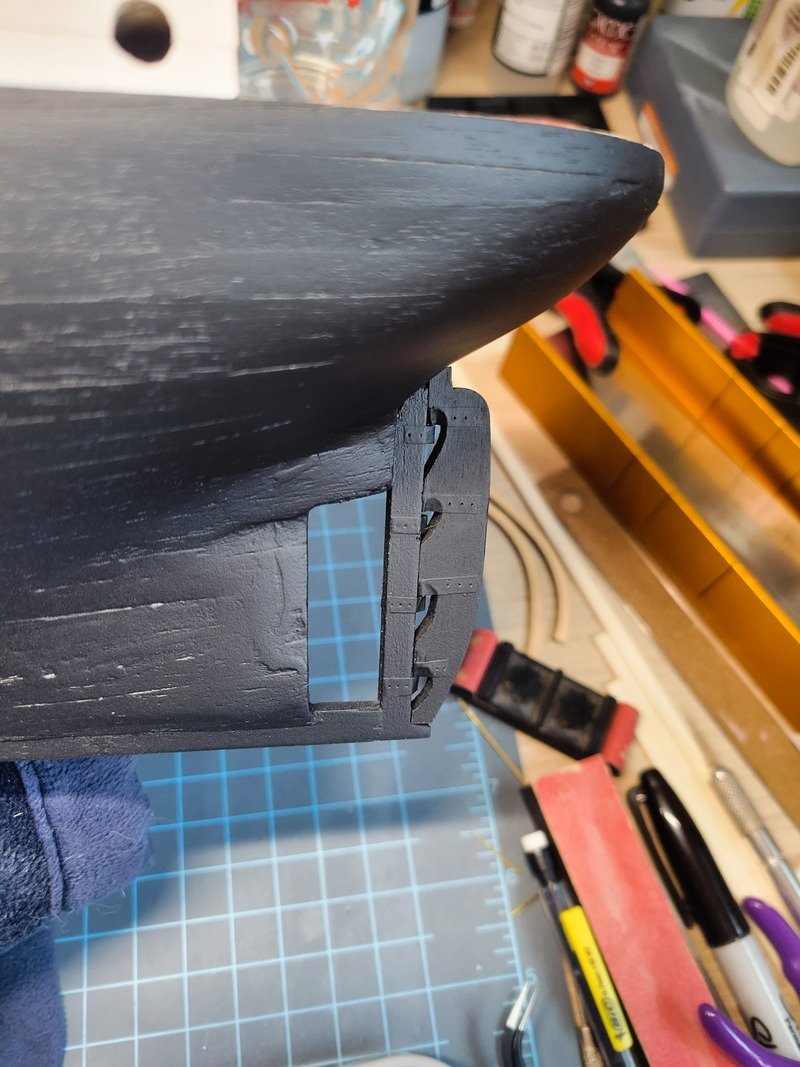
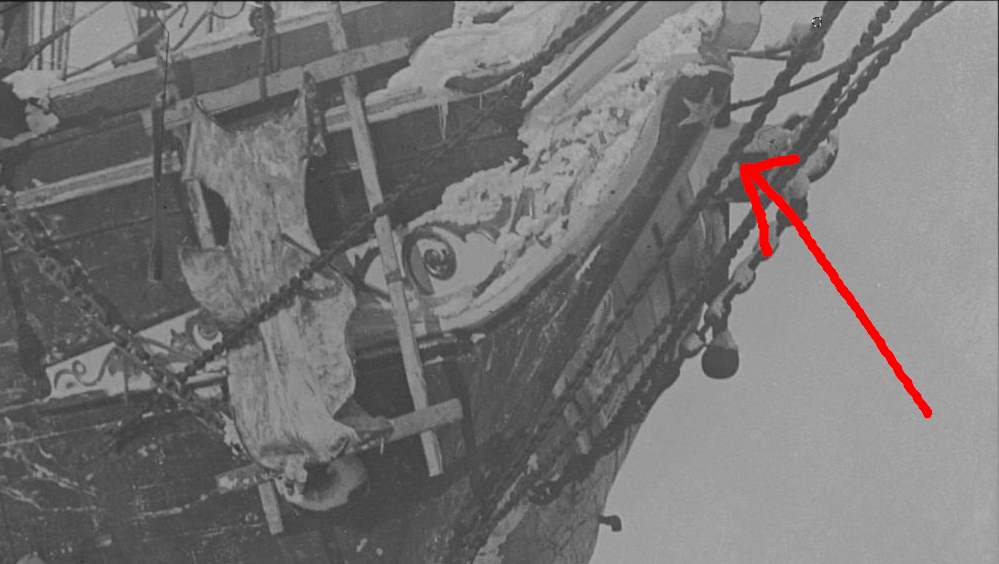
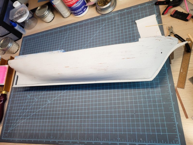
Hi folks, thanks for the likes and reading along with me. I wanted to go ahead and attach the rudder, so I took inspiration from Clearway's Endurance here and used a coping saw and a bench pin to cut the channels. I only have brass sheet in different thicknesses, so I attempted to cut 3mm strips from it which didn't work. I then grabbed some 6mm copper tape and cut it in half lengthwise to have an adhesive 3mm strip. Much much easier to work with, but it's not as thick as brass. These strips could be doubled up I suppose, but I didn't want to attempt it as it's finicky enough as it is. Holes were poked with a dental pick to simulate some sort of rivet. Then I added strips to the rudder post. Both were painted by hand and then the rudder glued on. If you look closely you'll see a gap big enough to give away the fact there aren't any rods or anything between the rudder and the post. This is just a suggestion of iron work on the rudder. I didn't end up drilling a hole into the hull for the rudder, I just cut it down and shaped the end to sit flush with the outside of the hull. No one will see it anyway. Next up was staining the cap rails/lining and install once dry. A bit of a sneak-peak but the bowsprit has been shaped and installed. I never once thought of what the bowsprit hole in the hull would look like after planking so imagine my surprise when I went to insert it. Round peg, square hole. It took shaping 3 sides of the aft end of the bowsprit to get it seated correctly. No need to take a pic of that monstrosity...it's in the hull anyway :-). Tapering was done on the lathe, and shaping to fit in the hole with a big file. Next up are the crazy-curved rails on the counter stern. I soaked the two pieces for around 5 minutes then slowly bent them around a Blaster can. To hold in place overnight I grabbed some velcro plant ties. I really hope this works, I don't have the best of luck when it comes to bending pieces to this extreme. Finally, I was perusing some reference photos and came across a star I haven't seen before. Also seen in drydock in London: So I decided to add it. I like the idea of easter eggs amongst the model, so we'll count the star as one of them. I'm planning on a Mrs. Chippy placed somewhere as well, and whatever else gets thought up. Thanks for reading!
-
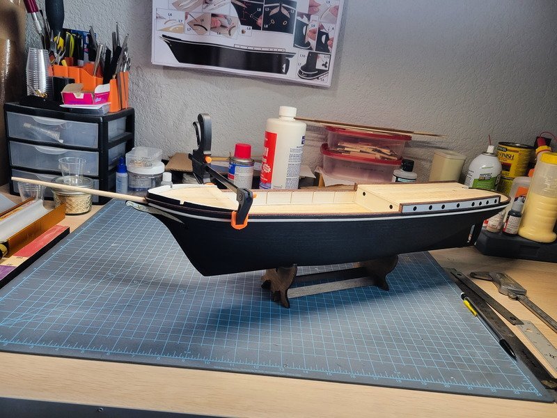
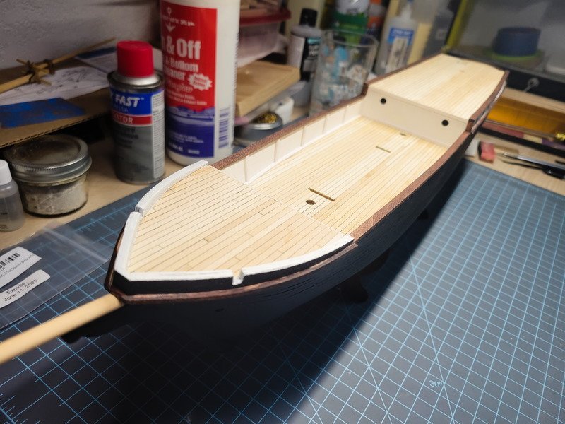
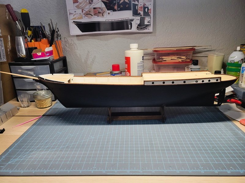
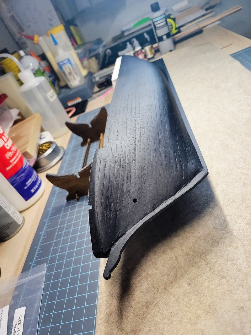
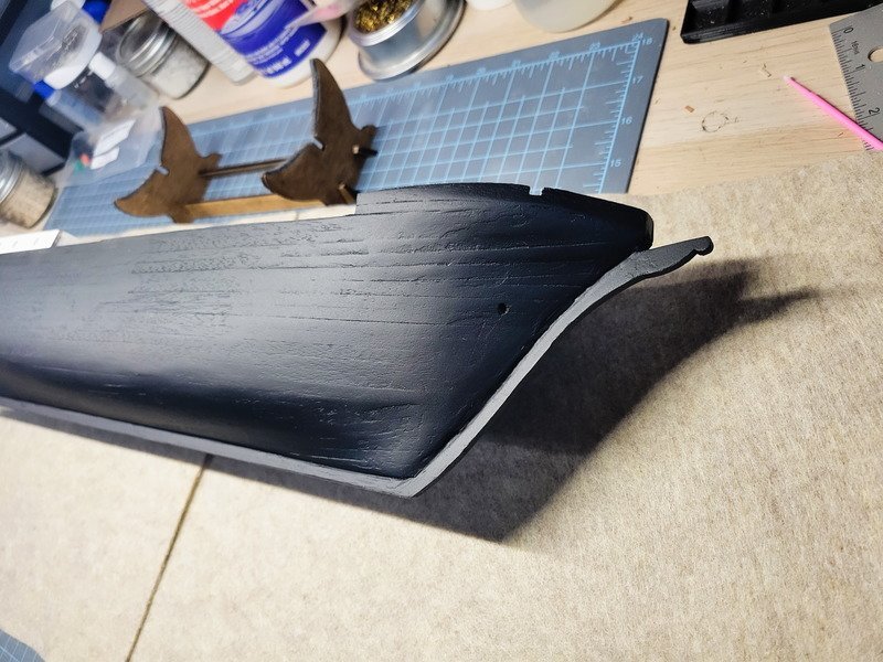
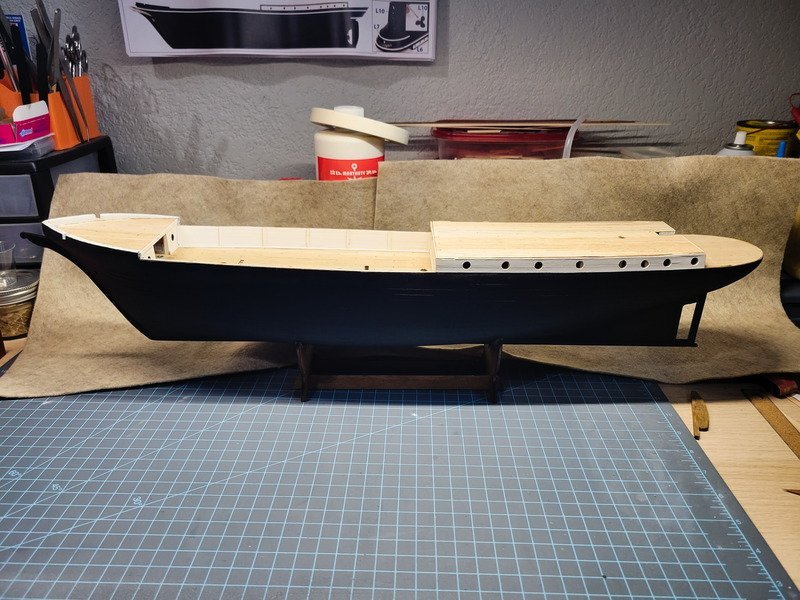
Thanks for the comments and likes! A big milestone complete, the hull is painted! I decided not to spend a ton of time priming and sanding, because I'm after the look of a well worked vessel. I also don't mind the grain showing through and quite like the effect I ended up producing. It took a few days of filling and sanding the second layer to cover a few wider gaps but overall I'm incredibly happy at the look and feel. This has 2 coats of Vellejo Grey Primer sanded to 1000g. (Out of order but that's okay) I sprayed white last on the cabin porthole areas and this inner bow bulwarks area. Up close like this the mistakes at the bow are glaring. I find I need to spend more time fairing the first layer of planks to get a smoother result. Both port and starboard at the bow are heavily helped by filler. The stern also fell apart more-or-less with the second layer. I was really happy with the first layer, and only decided to use the second because of the stern filler blocks. If I were to do it again I'd attempt to smooth the transition and paint on the first layer. I've said the last few days I want the starboard side as the display side. My second layer planking performance has dictated the port side is now the display side. Funny how that works, right? In reality I haven't fully decided but based on the previous pics you can tell the starboard side leaves a LOT to be desired. And we're caught up. Next steps are the trim which will be stained red mahogany before getting glued on. Then it's rub rails and hull decorations. The hull has been sprayed with two coats of matte finish, which should dull further overnight. It looks really shiny in the pics right now. I couldn't help placing the structures I've already built and taking a few pics. Nothing is glued down of course! Thanks for stopping by!
-
This is very true for this kit, and I'm wondering if going through the trouble of applying it was worth it compared to just filling and smoothing the stern filler blocks. It could also be my inexperience with second layers, who knows. Either way, both sides are complete and have had a few sessions of filling and sanding. The dreaded camera really shows the shadows, but to my eyes and hands I'd say we should be ready for priming tomorrow. I still need to finish up a couple of strips towards the bow, and complete the officer's cabin's portholes. A fresh layer of filler has been laid down, hence the bubbliness. I stopped trying to keep glue out of the rudder hole and focused more on getting transitions smoothed out. I'll probably drill out where it needs to go and round off the bit that goes in there. It looks like I didn't finish rounding out the starboard anchor hawse. The port side of the bow really seems smooth to me, but the pic says otherwise. When I go to sand off the filler that's currently on it I'll pay some attention to that area. I think I've applied filler and sanded 3 times now and am pretty happy with the result. Primer will show more imperfections, so I can decide to keep filling/sanding or commit since the hull will be a matte black. Oh yeah, the string acting as fish line for the anchor chains to go under the anchor deck became more of a chore keeping out of the way of me sanding. I ended up removing them. I have an idea using picture wire to get the anchor chains through, but at the end of the day no one would ever see or know if they ran continuously through the bulkheads or not anyway. Thanks for reading!
-
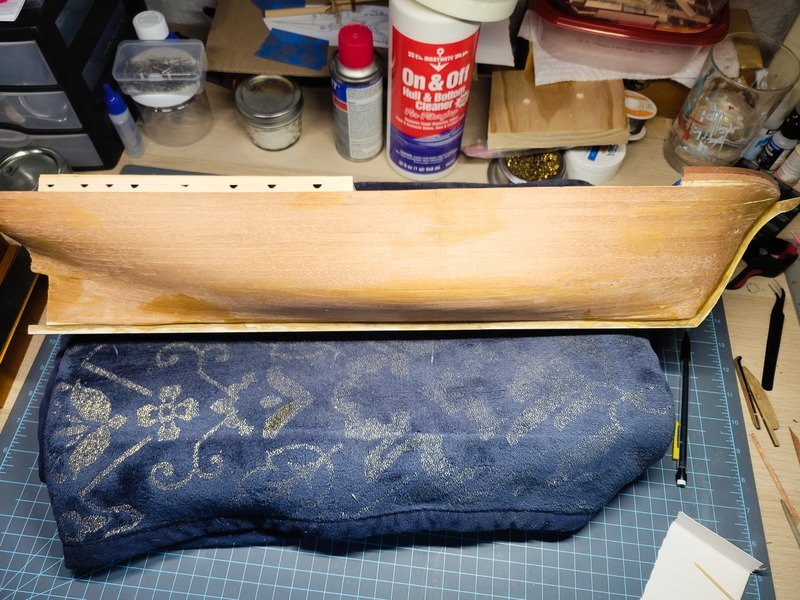
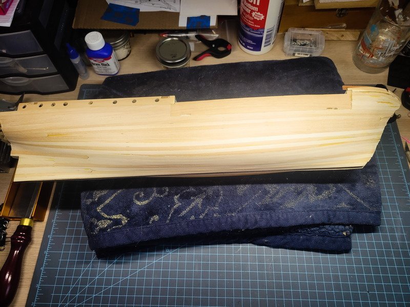
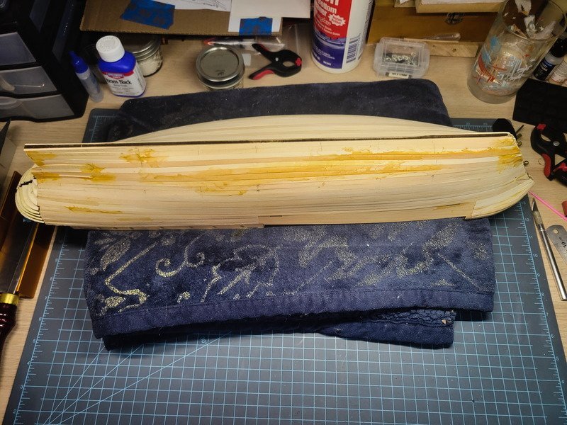
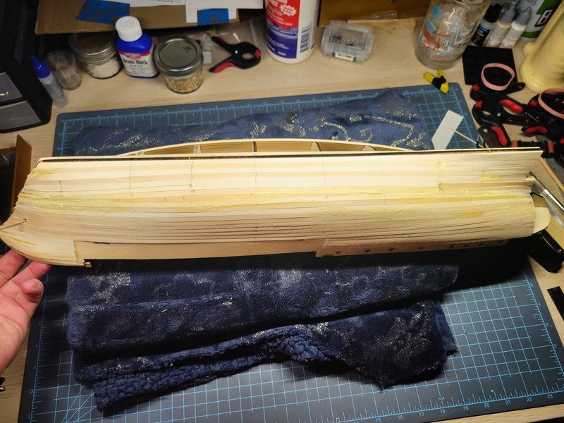
Hi everyone! This will be my first time applying the second layer on a model, so I made an assumption that I didn't need to taper, or have any kind of plan. I was definitely mistaken, and the counter stern shows. If I were leaving this natural wood I would've ripped the planks off and started over. However, since it's being painted, things will get the wood goop as filler and then sanded. I'll also be priming and sanding the primer quite a bit to get a nice base layer for the black. The port side is done, now to start on the starboard side. I am planning on displaying the starboard side, so the port was done first as practice. I'll create bands and tapers for the starboard, so maybe it'll go a little better. The planks were quite frustrating in some areas, but I'm confident with filler, sanding, and priming I'll be able to achieve a nice smooth surface for paint. Thanks for coming in!
-
I'm happy to report the port side has now been sealed. The starboard side has been sanded to 240 and I'm now waiting on the wood goop to dry on the port side to get everything smooth. I installed 2 stealers and when it came to the third, I decided I'd had enough practice and just sealed it up. Thus, requiring more goop. It'll all smooth out and get covered just the same. I'm also waiting on the stern to dry as well. Everyone is right to say it's easy to get them glued in backwards. I mentioned it a few posts ago, and I still managed to get them wrong the first time. Luckily I used wood glue for it so they came up easily enough. I was taking a look at the 2-bladed prop I bought for this model and realized it doesn't look like the prop she originally had. I don't know why it took me this long to see that, but here we are. I'll be buying a 25mm brass one if I can find it, otherwise it'll get modeled and 3D printed. Thanks for stopping by!
-
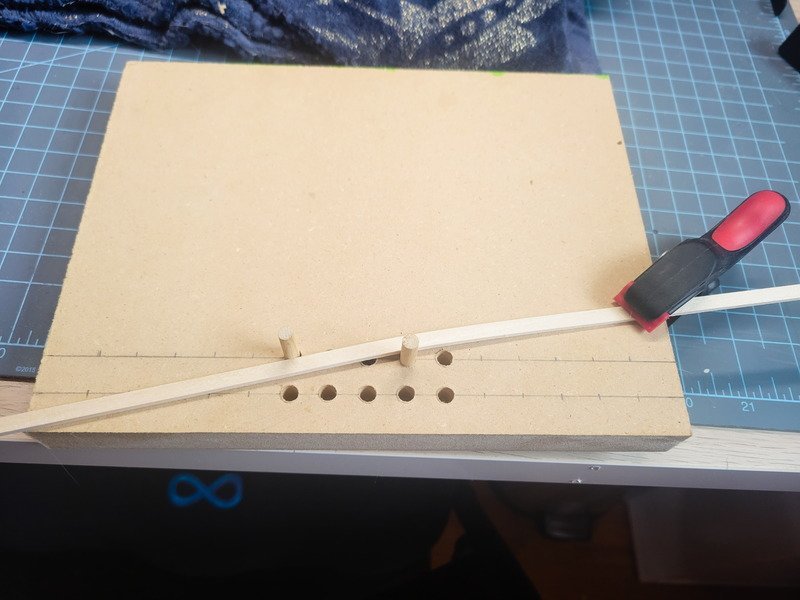
Bonjour François, here's the thread with the videos. There are 4 total. He uses a travel iron in the videos but on post #33 mentions the hair dryer. I ended up making a small jig with pegs I can move around to be able to edge bend. The pegs are too small and leave imprints in the piece being bent, but serve as a base for creating shapes that can slot into the pegs.
-
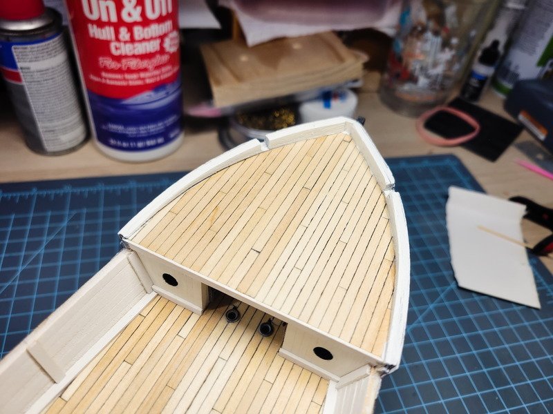
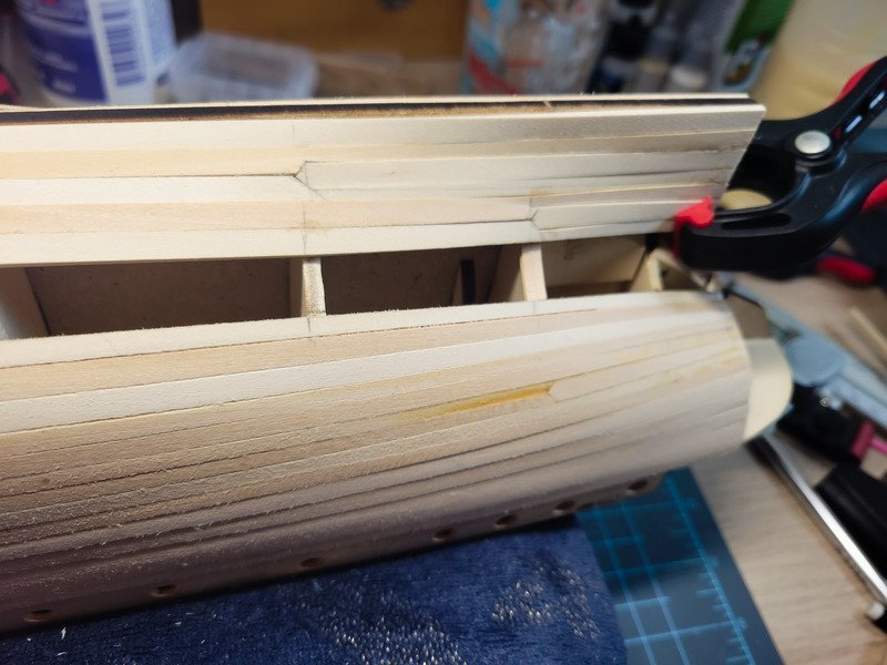
The clinker effect can be minimized greatly with edge bending per Chuck's instructions. I'm not sure what type of wood the planks are, but it seems quite brittle. I had issues bending the planks normally for the anchor deck "bulwarks" and had to use mahogany oddly enough. I soaked a few pieces for a while and tried that but the shaped pieces broke most of the time. What ended up working was finding Chuck's videos where he used a few drops of water and a hair dryer. However, even with that, edge bending didn't really work for the upper bow. I actually take no credit for this detail; Tom detailed it wonderfully in his journal and I'm just copying! Thanks Tom. That would be easy enough to recreate. Once the second planking is done I'll explore it more and see if having something under the deck makes sense.
-
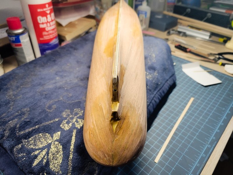
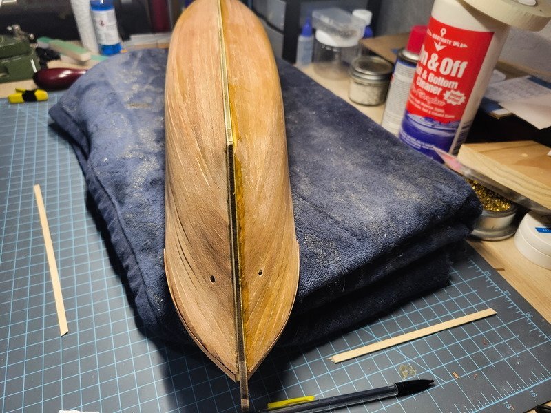
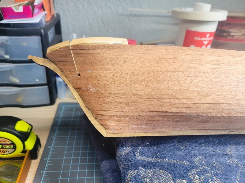
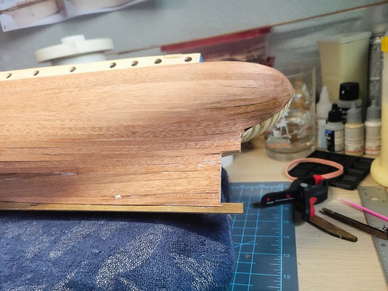
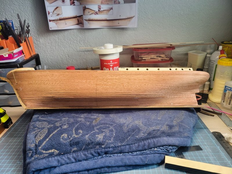
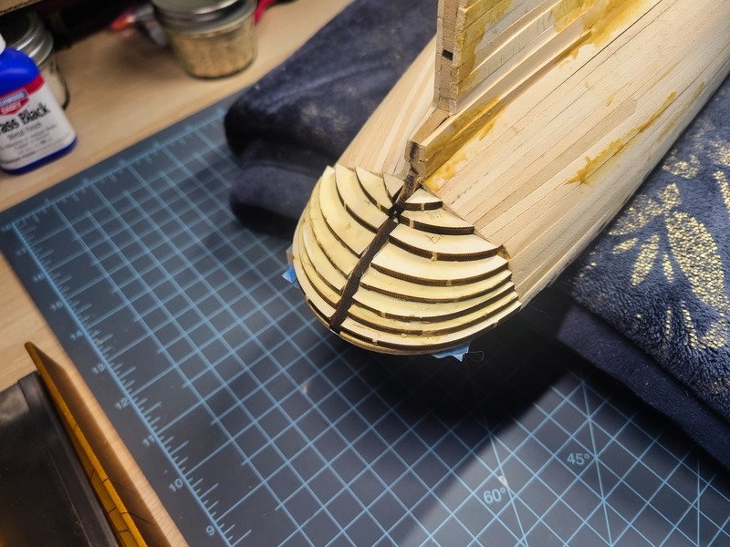
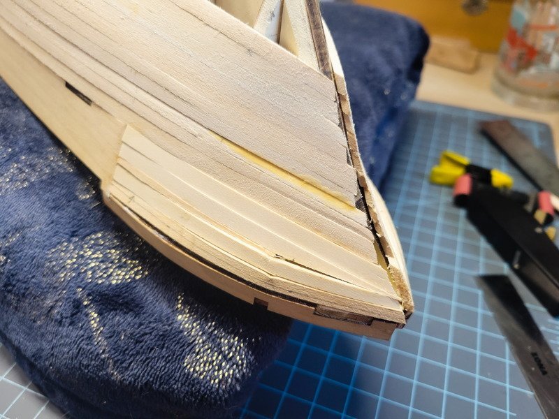
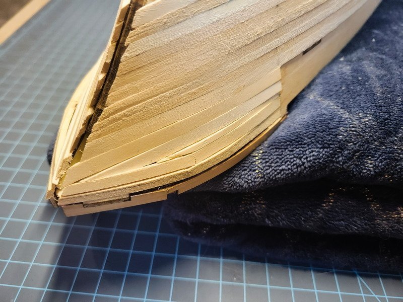
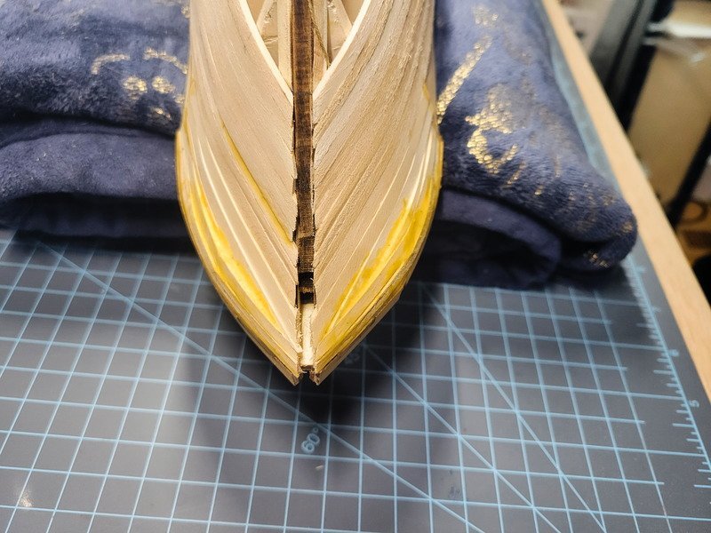
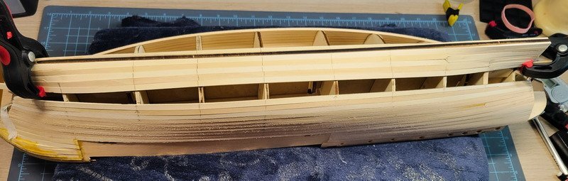
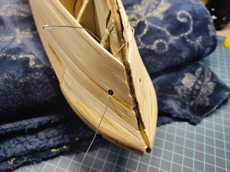
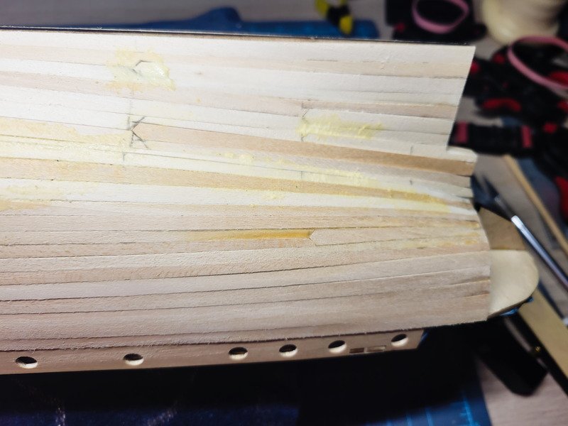
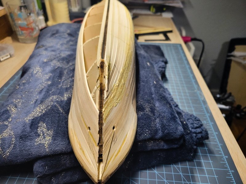
Hi folks, today was a saga and a half, but I'm happy to report the starboard side has been completely planked. Yay! I couldn't continue on the remaining bands until the upper bow was complete and I had the anchor hawse holes drilled. I was worried about that spot, and I was right to be worried. I broke a bunch of shaped planks trying to make the bend and finally lost my marbles and had had enough. It's getting second planked, so I just started throwing glue and wood at it until I got it sealed up. I added a ton of wood glue/sawdust and let it dry most of the day for good measure. Next up was installing both garboard planks. This was relatively event free, although I think I should've added a stealer to it as opposed to the plank below it. Either way, things went smooth. After the bow dried for a while I started sanding. It went by quicker than I thought, and the result is smooth and convincing. I'll inspect it more tomorrow, but I think the shape is 95% there. I used some galvanized picture frame wire with a hook in one end to grab the thread and pull through the anchor holes. And before anyone asks: yeap, one of the planks popped up when the hole was drilled. I glued it back down no problem, but could've been avoided by gluing the sides of the planks in that area. I threw the measurements to the wind more or less at this point and my final plank was a ridiculous 1mm wide in some spots, but I got it sealed up and covered all the gaps with my wood glue/saw dust mixture. It'll dry overnight and get sanded down tomorrow. The stern ended up requiring 3 full stealers and 1 drop plank. While finishing up the stern I grabbed the rudder support piece and tested out the 2-bladed prop I have. It only needs 1.5mm of movement forward to fit, so I'll be doing that once the port side is finished. It won't change the shape of the hull too much. Thanks for reading!
-
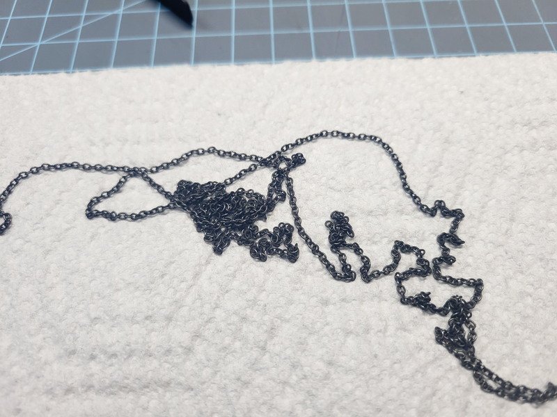
Interesting...so it worked? I have the same stuff. I attempted to use it on the stanchions for the chest ironwork and it worked really well on the top and bottom surfaces because I sanded them. The edges though still had whatever coating is on them and didn't take the black at all. I assumed the chain is coated in the same thing so wasn't sure I should even try it. I'll give it a shot though before I buy new chain.

