theoracle09
-
Posts
152 -
Joined
-
Last visited
Content Type
Profiles
Forums
Gallery
Events
Everything posted by theoracle09
-
 You have good points Johnny. I don't know if my attitude is the right way to think about it, but I've never cared about copyright because I'm not profiting for the material I am referencing. I'm not profiting from the material I produce, either, and have zero interest in doing so. I don't know who owns the images I post, and have no inclination to find out. Getty seems to have the majority of images, but I've also going to google images and searched different key words to find the lesser-known images I've posted. I'm with you Keith; while I'm striving for historical accuracy I mentioned in my first post I'm only shooting for 90% or so. The square windows in the ritz don't really interest me enough to cut them in and figure out trim, or suggesting glass, etc. Do you mind providing some measurements on your stovepipe? It looks to scale, so what's the height from the deck and the diameter of the tube you used? Also, did you make the top bit? I've been puzzling over how to create that as I don't have any brass sheet (other than PE sprue, if you call it that).
 -
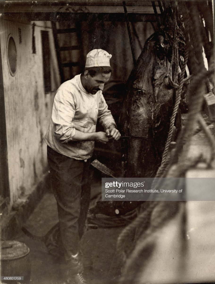
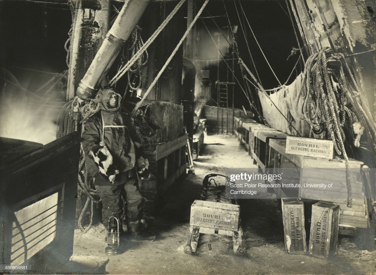
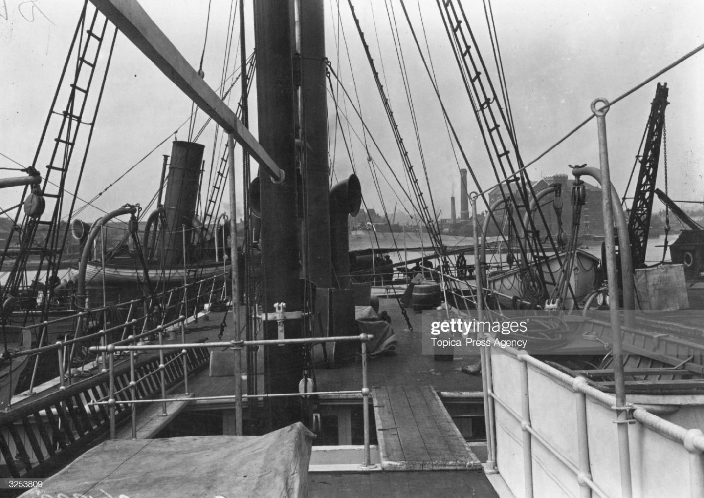
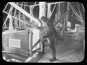
That particular photo is post departure, as that's of Perce Blackborow who was a stowaway that wasn't brought to Shackleton's attention until after they had left Buenos Aires. I can't definitively say this chimney is for that stove, but there is a chimney that comes out of the forward port side of the ritz in these pics: (which I think you mentioned in your post when talking about that porthole on the ritz inboard of the galley stove).
-
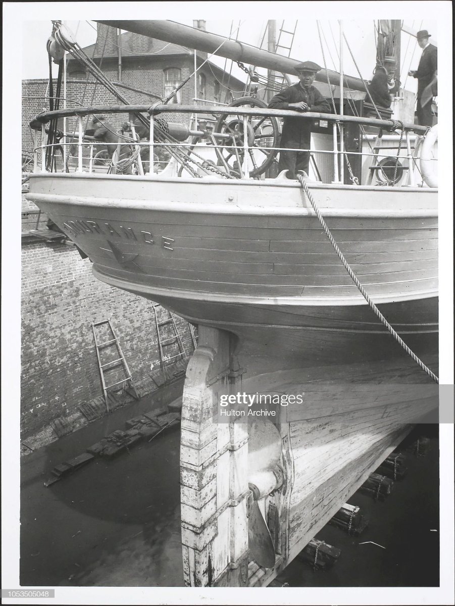
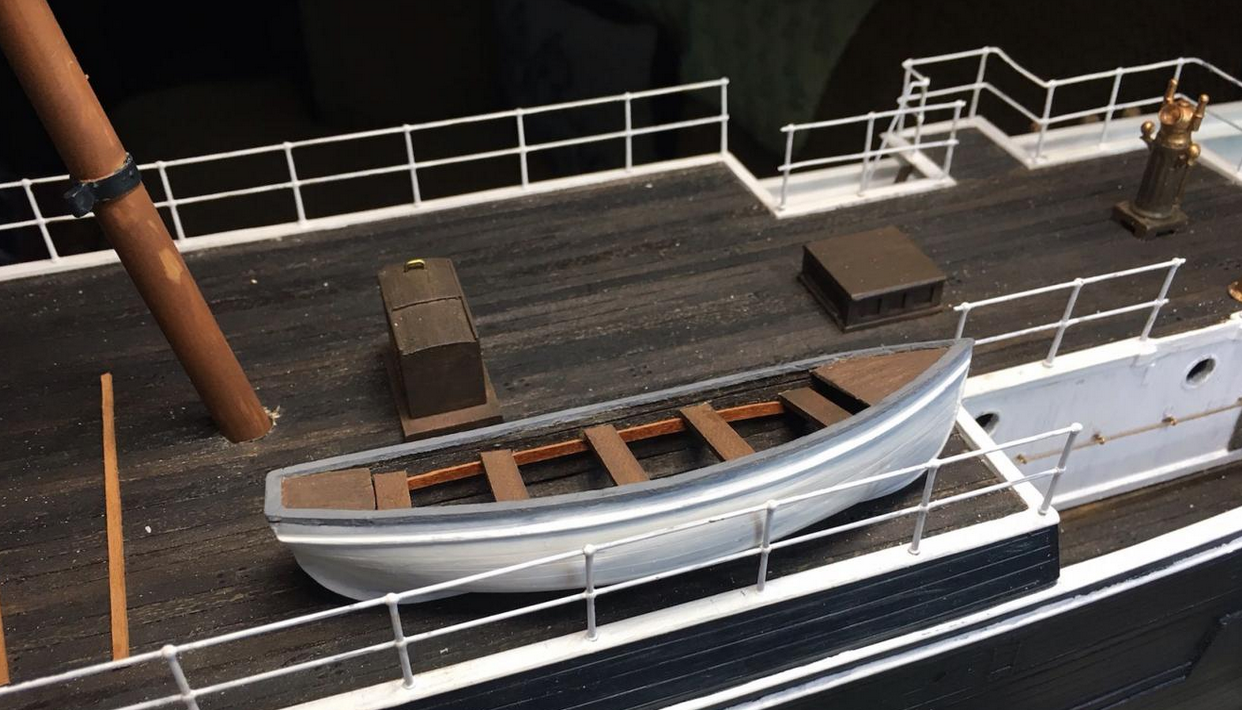
Thank you for the kind words, Johnny! Thanks Craig. Here are a few more of the interior of the ritz I've been able to find in addition to that link you posted: Additionally, here's another shot of the port wing. It's interesting, as both this pic and the one with Mrs. Chippy and Blackborow show a square opening in the wall. Any ideas what this may have been? I'm not too sure I'll be bothered enough to model that skiff. I'm already planning on replacing the lifeboats with ones from Master Korabel, and by then I believe I will have spent more on upgrades than the actual kit itself! I do plan on scratch building the aft companionway to better match that same pic (with the skiff in it). I'm not using the steering gear deckhouse, but it does have a curved top that might just get re-purposed into being the companionway. In pics, it doesn't appear to have a sliding top, unless the entire top itself slides. But it is definitely a different shape to what OcCre provides. Here's another angle I've found from the London shipyard. If you zoom into it, you'll notice rectangular windows that aren't in the kit either.


-
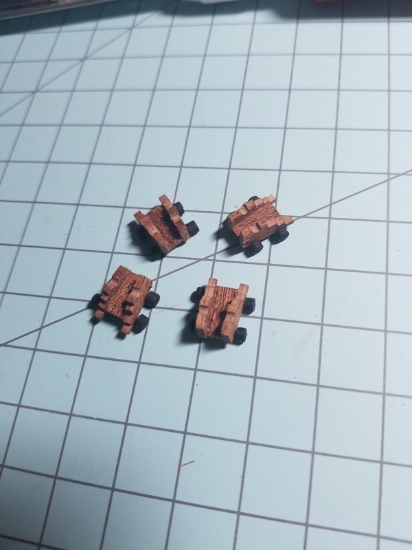
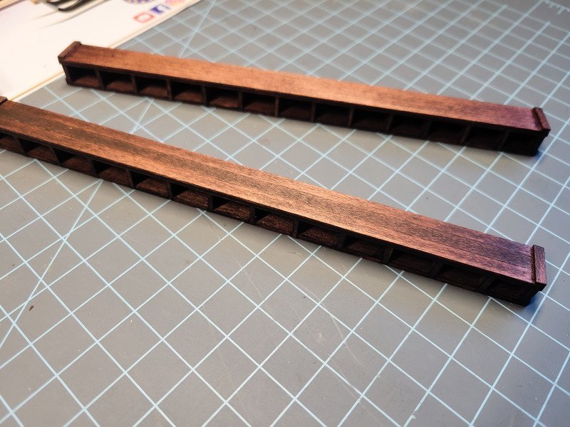
HI folks, I finished up the dog kennels yesterday. All in all it took quite a while to complete them as sanding the laser char off of everything that faces the viewer was a pain in the butt. It always gums up the sand paper which has to be changed frequently. I'm extremely happy with the result though and it makes all the time spent on them worth it. First step was staining the inside of the kennels. I used Minwax Red Mahogany for this. The "Espresso" color I was contemplating seemed to be too dark as the hull will be painted black. It would've been too much black all over the ship. The red mahogany isn't actually as red as I initially remembered/thought, so it worked out. Once the stain was dry everything got glued together, and I began to line the outside of the kennels with the 0.6x5 strips used for the decks. The instructions call for the dark sapelli veneer but after staining the skylights, which are lined with walnut (a darker wood) I found out the red mahogany gets almost too dark. Had I lined the kennels with the darker veneer like it calls for these would've been entirely too dark. I laid the strips out on upside-down tape again and glued them to the kennels that way. The instructions don't call for lining the top of the kennels, which would have looked strange had I done it that way. I think it looks better lining the tops as well. After sanding everything down in the last picture, I added the final bits and then final coat of stain. I really like the striations of the wood coming through the stain. I think it'll be a nice dark color to contrast against the deck once it's all installed. Thanks for stopping in!
-
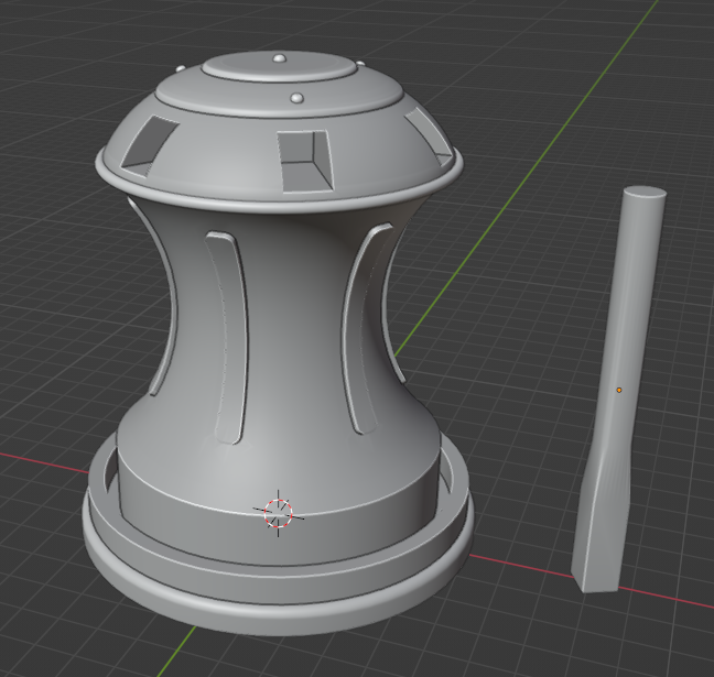
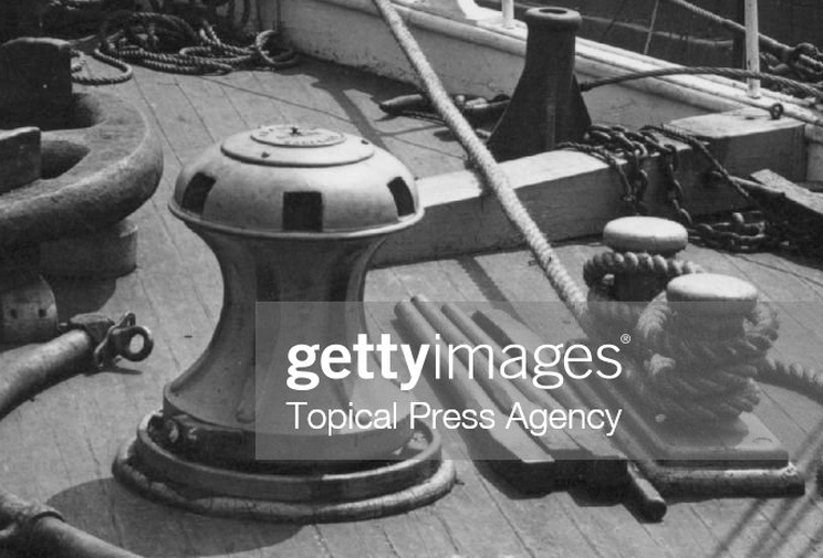
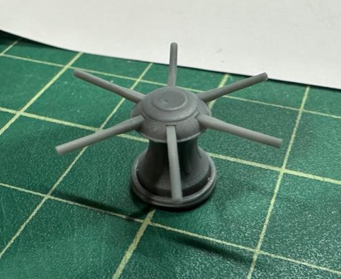
The capstan leaves a lot to be desired and from seeing it in other logs I knew I wanted to find a way to change it. Modeling it isn't a problem, and was complete in a couple of hours. Reference: Model: Print: This was printed by @Hunt270 on his resin printer. I think it'll be a marked improvement over the bit of wood the kit provided! Thanks again Will for offering to print it out.
-
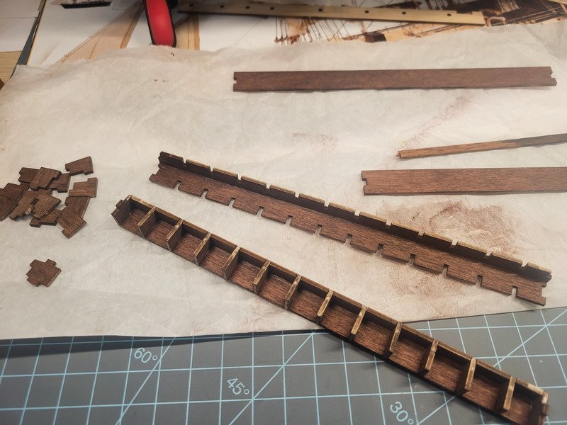
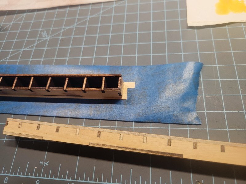
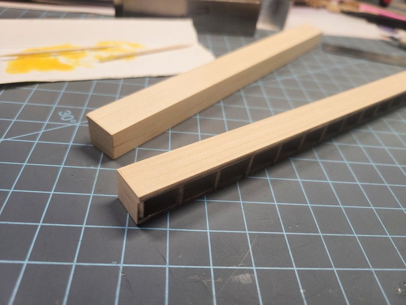
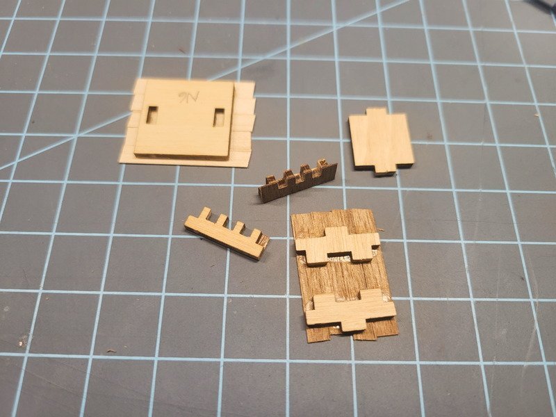
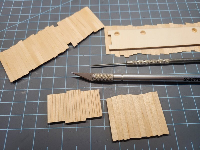
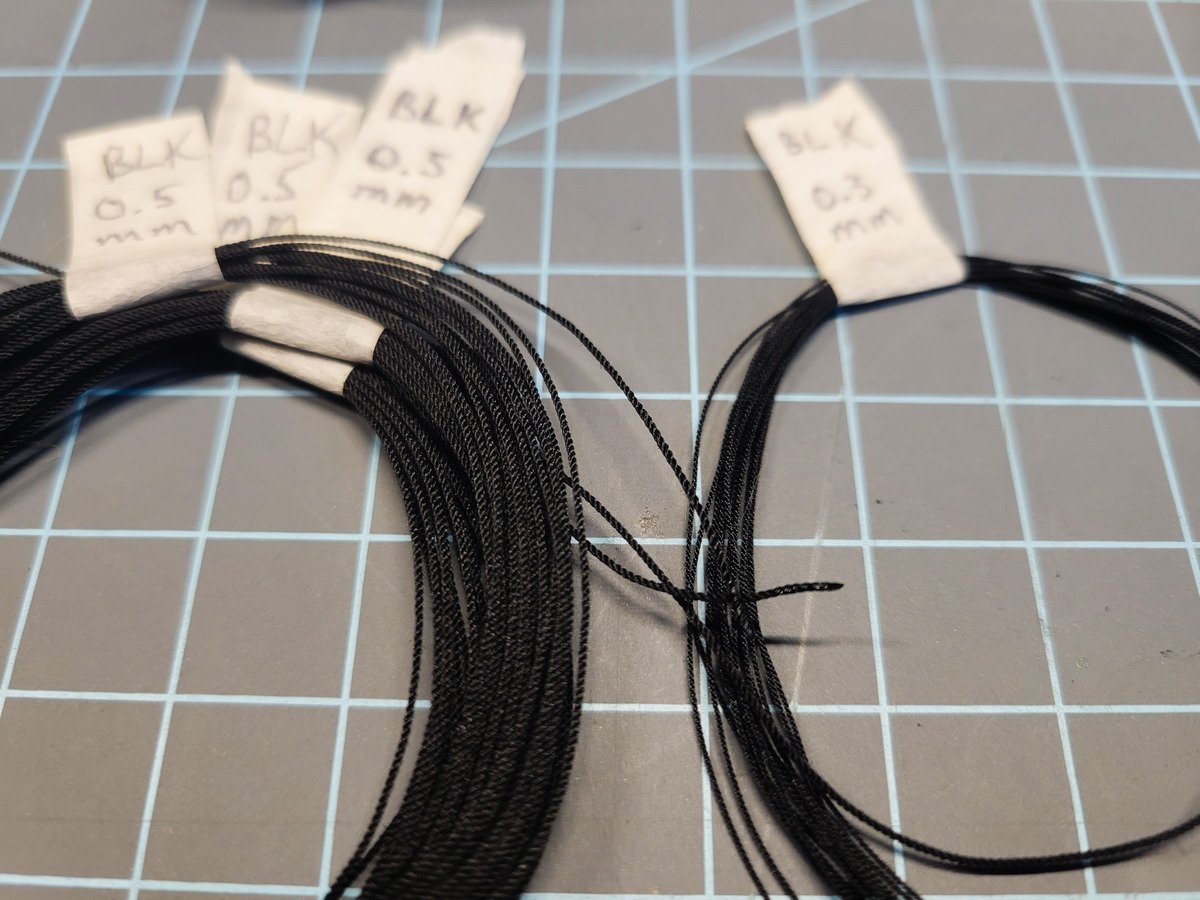
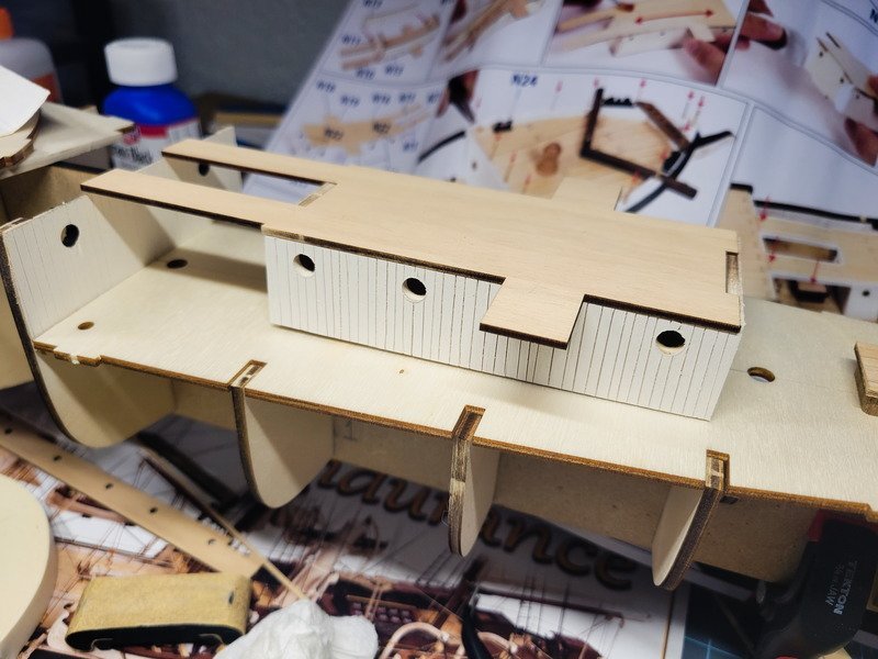
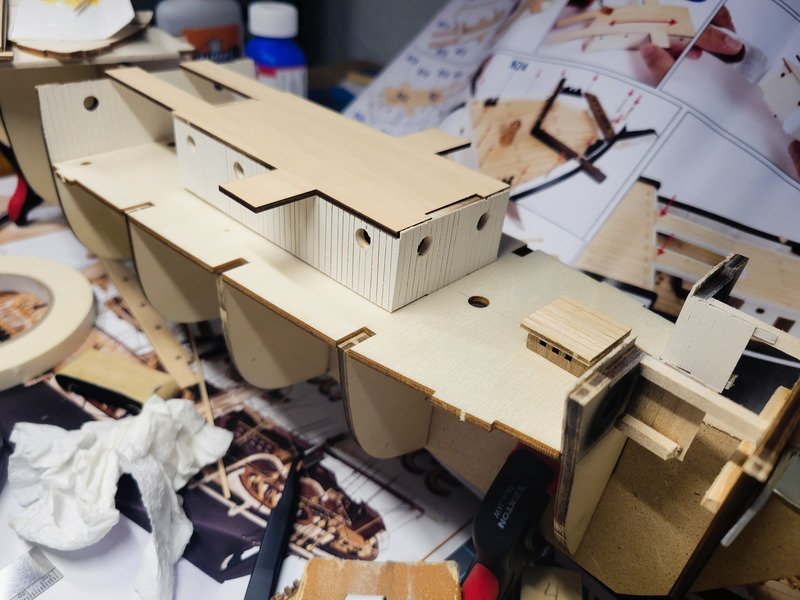
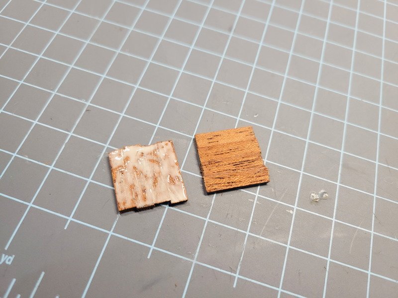
They're nice, but not accurate it would seem. That's alright, I'll still enjoy building and displaying her. As far as progress goes I have a stock of 1/32 x 1/8 x 24" Basswood Strips arriving next week and can continue on to the decking. This gives me a plank width of 3.2mm, or 8.75" real width. In the mean time I've made progress with two of the skylights by planking the sides with walnut veneer from the Newport (second planking wasn't used). I stuck the veneer strips to upside down masking tape and then glued the laser cut ply to it. The roof of the skylight is picture in the top left using the 5mm veneer meant for the decks. After cutting the excess off I used an xacto knife to cut every 2.5mm, then drug a dental pick through the cuts to provide a noticeable gap. This same technique (thanks again Clearway!) was used to plank the sides of the ritz. Comparison of the "fake planks" and the regular 5mm planks. It's a really nice effect without having to glue individual planks. Just have to make sure the lines are straight, which I messed up 1 or 2 here and there. With everything else to look at once it's all complete I'm not too worried about it looking off. Next up was paint. I still need to paint the inside of the portholes black. Also to note the frames are not glued in yet. I'm going to plank the decks first and make sure all aligns well before gluing those. The skylight will have a dark-stained wood as trim but I haven't decided on what I want to use yet. Instructions call for Sapeli or something like that, which looks to me like a mahogany. I do have red mahogany, but it's pretty darn red. I may experiment with an Espresso stain (can't remember if it's Verathane or Minwax), as that's relatively dark but allows grain to show through. Not sure yet. Lastly I put together a homemade ropewalk with 3D printed gears. It works extraordinarily well, and I'm now waiting for some Mara thread to come in. I practiced with some black and even the very first rope made looks awesome. The 0.3mm was made with black thread (came in the Newport kit...no idea what it actually is) with 1 thread per strand. The 0.5mm rope is made from the same thread, but 2 threads per strand. The 0.5mm has a total of 6 strands in it. I tried using beeswax (high quality) and really rubbing it in. Creating heat between the rope and my fingers to get the wax to melt and smooth over. I was left with splotches of gloss, where it almost looked white where the wax took and then black where it didn't. None of the ropes in the above pic are waxed. Thanks for reading!
-
I agree as well. Whenever the aft of the ritz was decked over would be when those changes were made I imagine. I found this pic, and if we're saying the skylight is under canvas, directly in front of the binnacle, I believe there would have to have been a hatch between the skylight and the main mast. It also appears the kennels on the bridge (the ones in the video) were removed? But at least this pic clearly shows it was decked over. On the main mast, where the boom connects, there's a white strap around it. That's also seen in this pic: It appears the "polar configuration" that I'm going for would require the same decking-over. This is where I'm deviating again from historical accuracy, as I quite literally picked this kit because of the gangways above the quarterdeck. The detail stood out to me, so I bought it and then started researching. It's awesome to continue to research it though, as every time I zoom into the pics I find new details.

-
You're not wrong! Another curve ball to add to the pile is a youtube video I came across which shows the bridge having dog kennels on both sides, and seemingly no hatch OR skylight to boot. As the man moves you're able to see the main mast behind him. Additionally, in the same video, there's an opposite angle for a few seconds where neither can be seen. It really is unfortunate a lot of the negatives couldn't be retrieved. I imagine if those had been saved these types of questions would be more easily answered!
-
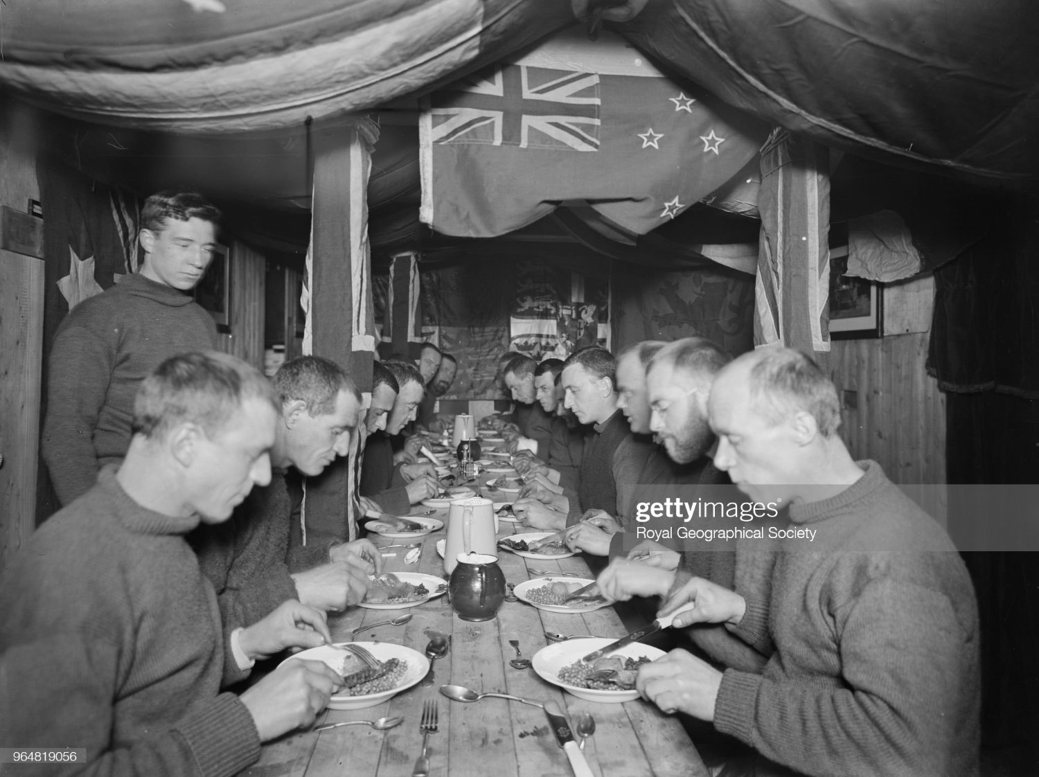
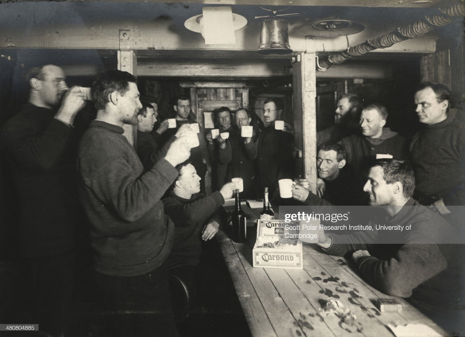
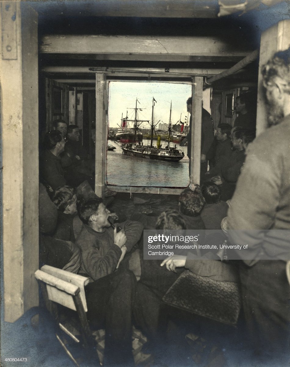
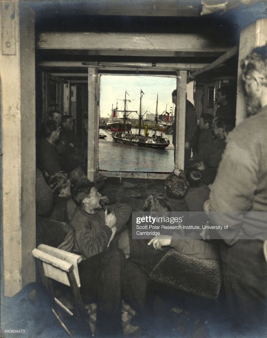
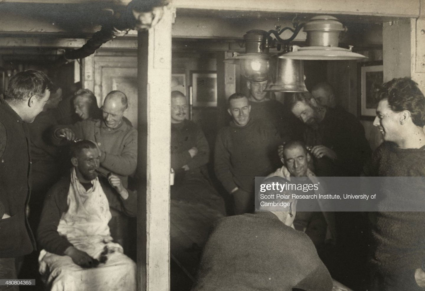
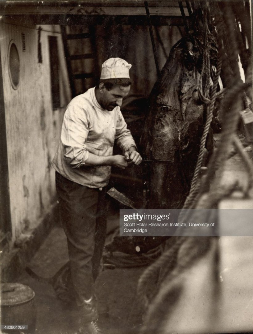
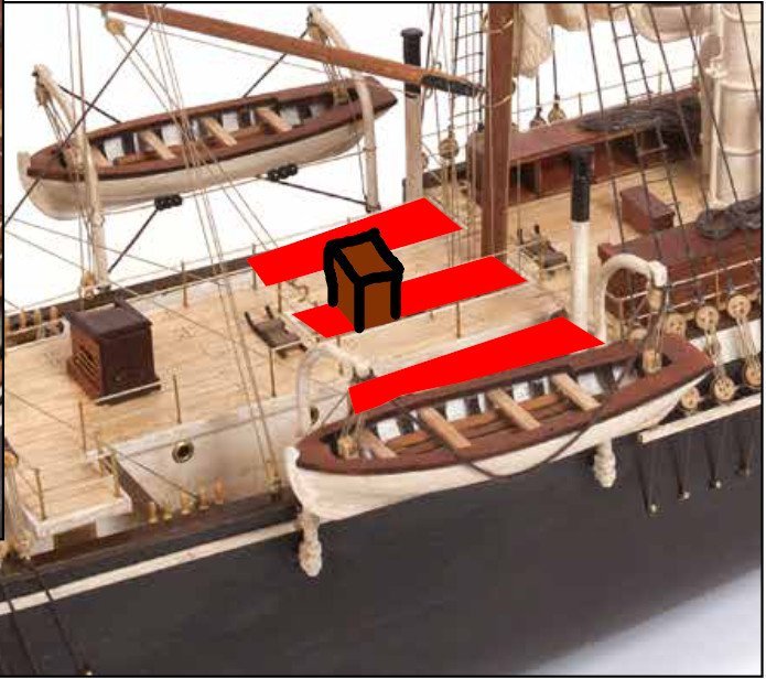
Thanks for stopping by Craig! I appreciate your post. I'm inclined to disagree, however, because the distances don't add up. What I mean by that is in post #11, the two pics I included show a man in frame of the picture. If he were to lay down between the main mast and this hatch we're discussing, it looks like he'd fit and touch both the mast and hatch. This puts the distance of that hatch from the main mast at ~1.8m (or closer). Using your 4th picture, the tan one of the drawings, take a look at the fore starboard lifeboat. It fits between the skylight over the ritz and the main mast. Alfred Lansing, in his book Endurance, noted two sizes of lifeboats: 21 feet 9 inches, and 22 feet 6 inches (putting both at 22' would be ~6.7m). I believe this distance to be too great to reliably say the ritz skylight was converted to a hatch, in the same position where it's noted on the plans. Finally, I have two non-empirical thoughts: as HakeZou mentioned in a post I linked above, had there been a ladder coming down from the ritz skylight, we'd see it in pictures from inside the ritz. I've only found 3 or 4 of such pics: hair cutting tournament, eating dinner, and tinkering with scientific devices. No ladder. My second thought is based on the following image from a museum-quality Endurance model (donated to the South Georgia Island Museum by Ken Greenwood): With the measurements and the museum's model, I'm going to opt for building the skylight above the ritz as a skylight. Certainly anyone can build whatever they want! But for me, I feel comfortable explaining why the skylight above the ritz was never a hatch, and thus would not be historically accurate to the degree I'm aiming for. Good points all around Clearway, thank you! I didn't think of modeling the homemade pointer and will definitely be planning on including it.
-
Daniel this is looking amazing! I love the lights you're putting in, and the rivets are an awesome technique I'll have to remember the next time I need rivets.
-
After searching for a couple of hours on the skylight above the ritz I came across this link of a Tehnoart kit built by Ken Greenwood. In the pics at the link it shows the quarterdeck enclosed aft of the ritz, and has the main mast and hatch as depicted in the images in my last post. With this confirmation I'm changing the hatch on top of the ritz to be a skylight. I'm not going to be decking over like the model in the link, rather I'll stay with the gangways as represented by OcCre.
-
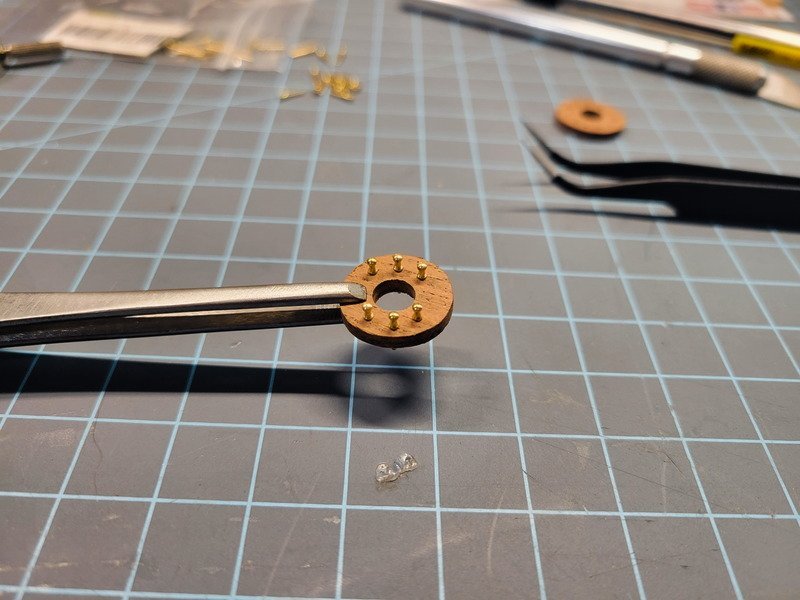
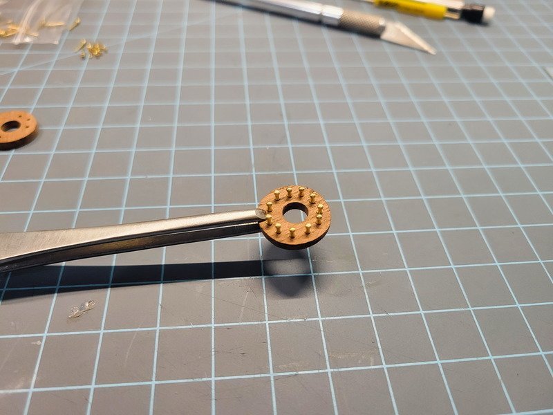
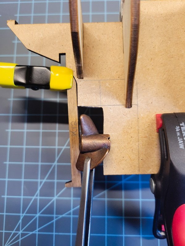
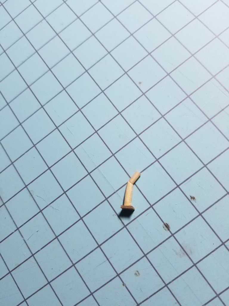
Thanks Keith, I appreciate your pointers, keep 'em coming if you don't mind! The prop is bronze, and the blades actually clear. It's the shaft that's ~2mm too long. Here's a pic: The blades are flaired aft as well, and would hit the stern post if rotated. Normally I'd just lop off some mms on the right side of the prop box but I really don't want to change the shape of the hull. It'd be worth it purchasing a smaller one and keeping this in the spares box. Your plank solution would work had I not painted it already, and I'm just lazy enough not to strip it, gouge it, and re-paint. So I used an xacto blade and it worked to my satisfaction. However moving forward I'll do that! I spent a good portion of yesterday attempting to find a way to split the deck planking in half, or even in strips of 3mm with 2mm cut-off, all to no avail. So, the admiral approved new deck timber but it seems my two US sources are out of stock of 3mm wide planks in the quantity I need. I haven't found a source yet, but I can't bring myself to use the 5mm wide strips for the deck. It would certainly be a beautiful ship (my skills depending) and others have produced amazing Endurance models using it. I think I saw a link to a few timber yards advertised on these forums so I'll do some searching and hope to secure a stock of it soon. Since the deck planking is on hold, the entire hull is pretty much on hold. I started looking at and planning for the deck superstructures. One thing I planned on changing from the beginning were the eye-bolts on the deck for the mast rigging. The rigging just terminates into the rings, with no coils or way for the sailors to actually use the ropes to hoist or stow anything. After spending too much time on Getty and Google images and not finding a picture of the deck where the masts are, I took some 5x2mm mahogany strips (I have a ton from the San Fran 10+ years ago) and glued 4 together to get a 20mm x 20mm square. With 4 planks glued together I then glued an additional 4 planks into a square and glued both panels together, with the strips turned 90*, for strength. The squares were turned into circles using hand sanding blocks, I flattened the panels to 3mm thickness (instead of 4, that was too bulky and thick), then drilled for the mast, then drilled for the belaying pins. I'm using 8mm brass belaying pins throughout the ship which will be blackened before final installation. The fore and mizzen mast pin rails are complete. I'm not confident a rail of the same size will fit between the main mast and the bulkhead aft of it, so once things are a bit more built up I'll have a better idea of spacing. For now I'm planning on a U shape, but if there's room I'll do a circle. Finally, some questions to those who have researched the Endurance. Clearway, I noticed on your log here there was discussion on why you're including a hatch on the roof of the ritz. You reference this picture: Then I ran into this picture: Note how the hatch is facing port in the first image, and aft in the second. Are these the same ships? Can a hatch be easily rotated? Additionally, I'm not convinced the hatch pictured in both images is over the ritz. It looks more to me the bridge was enclosed to the bulwarks, so the quarterdeck was completely enclosed. The hatch pictured would then lead to the skylight on the quarterdeck between the aft bulkhead and the aft wall of the ritz. Here's my interpretation of the above two pics: With it drawn out, I'm inclined to agree with HakeZou here when he says there was a skylight over the ritz and no hatch. Especially because we have photos from inside the ritz and none of them show ladders or stairs coming down into it. For these reasons I'm not going to model the hatch over the ritz, but change it to a skylight which looks more like the picture HakeZou provided in the post I linked above. Alright I think this is long enough...thanks for stopping in!

-
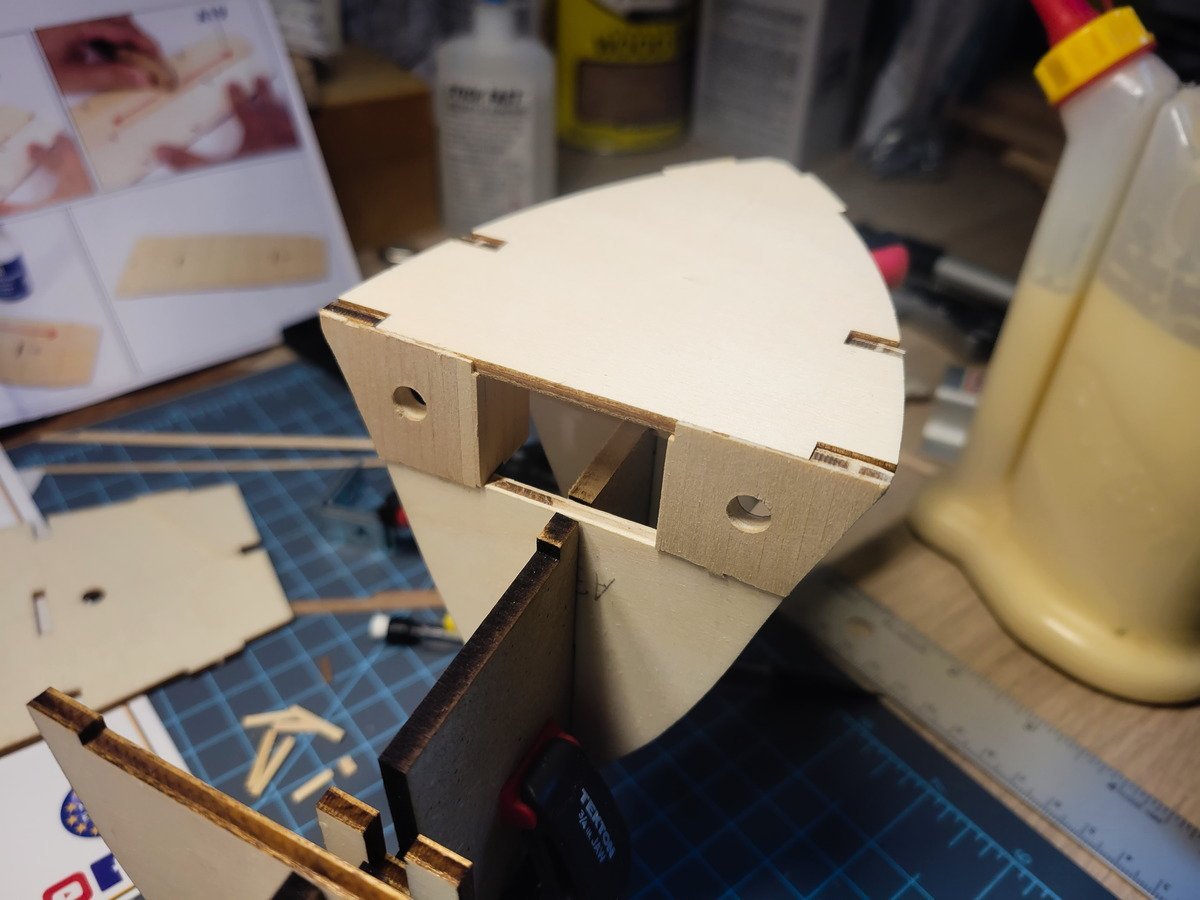
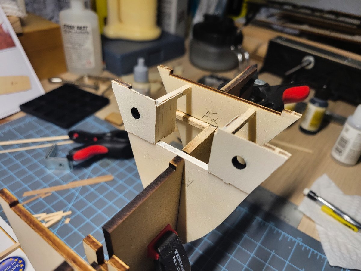
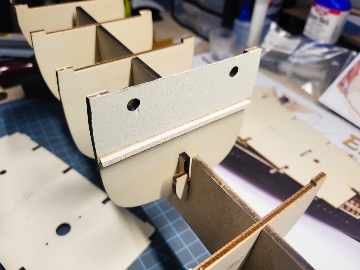
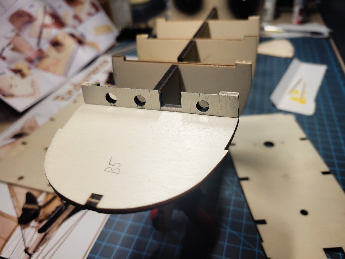
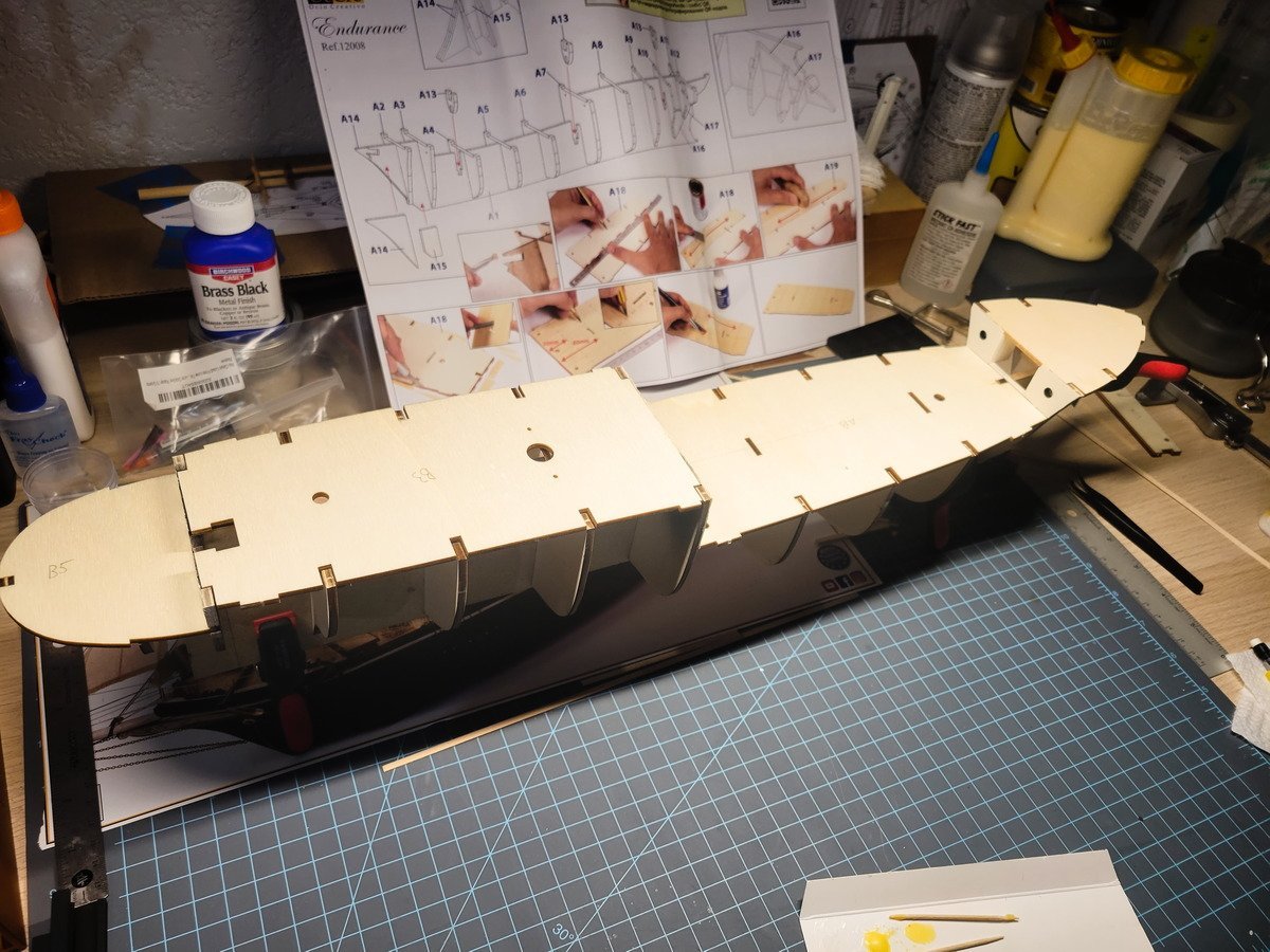
Hey everyone! I have received the kit and begun construction. Yay! I need to count the blocks and see if I'm short as others have reported. Otherwise, everything is in good order and I was fortunate during the shipping process nothing happened to the MDF false keel as others experienced. First steps of course are to remove the false keel and the bulkheads from their sheets and file down the connection points. Everything has been dry-fit and adjusted, and then I started planning for the open space under the forecastle. After making the cuts and assembling two false closets, I was left with the below image. I also drilled out the portholes to 1/4" using a forstner bit. I centered it the best I could and used a drill press to slowly, very slowly, start cutting through the bulkheads. I didn't experience any tear out (there was wood behind the bulkheads. which the bit went in to) and used the same method after planking 3 bulkheads to cut through the planks once the glue was dry. Unfortunately I sanded it too good apparently because when I applied paint, the plank lines pretty much disappeared, which meant the few hours it took to cut and glue them on don't really account for much. On the above bulkhead I added an extra strip to support the deck. Note here as well the planks disappeared when I airbrushed the paint on. I am probably going to find a way to sand, cut, mark, or otherwise suggest the planks. Off the top of my head I imagine using a dental pick or something similar to indent the wood, but not scratch the paint. I'll deal with that tomorrow. Maybe just mechanical pencil would be enough, too, but rather light. I didn't sand this aft bulkhead's planks due to what I learned from the first two and it shows. After enlarging the portholes here there is a mere 2-3mm for the vertical planks to stick to, so there was definite tear-out on the left two portholes. Admittedly, I should have waited another few hours to drill out the portholes, as I don't believe the wood glue I used was hard at all. Just set up. It's all good though, there will be trim that covers that up. It doesn't look like much, but there's a lot going on that I didn't picture. I cut out the propeller box because the half-moon shape doesn't make any sense. I made sure there was about a 30* angle on the top cut, but it doesn't really come through after I sanded. I'll have to adjust it anyway as the 30mm Amati 2-bladed prop I bought doesn't fit in this space as-is, but enlarging the box will change the shape of the hull. I need to decide to buy a 25mm prop or make the 30mm work. Let's see, what else: Inside portholes painted black Walls painted with a 10:1 mix of white to bone white (Vallejo) [All white paint will be this mix moving forward.] Bulkheads faired to sit flush on false keel Nothing is glued right now which is why the decks are bowed up and look strange As for the deck, that's pretty much the next step. The kit comes with 5mm wide veneer, which is entirely too big of a size for the Endurance. Seeing as the deck is one of the major things we tend to look at while observing these models, and I passionately want this to be historically accurate (95% at least!), I attempted to cut the strips in half using a metal ruler and fresh xacto blade, to no avail. I cut the main strip down to the length of the main deck extending into the space under the anchor deck and after several attempts wasn't able to cut straight down the middle length-wise. The grain moves the strip ever-so-slightly, which when stacked next to other similarly-not-straight strips the result is definitely not something I'm after. As for cutting it took 5-8 strokes, as I applied the lightest pressure I could to try and mitigate the side-to-side movement. So, I don't have anything 3mm wide (or rather, I don't have enough of it) so I may try to think up a jig to attach to a table saw cross cut sled. If the strips can be taped down over the kerf line in the sled, and the blade doesn't rip it to splinters, it's possible I can cut them down that way. Finally, I've always been curious on the raw time spent at the desk per model. So I'll be tracking every hour spent, with a very small description of what happened. I think it'll be cool to be able to say "yeah, this one took 8,000 hours" and mean it. So far (including the work done on the funnel before the kit was received) I am at 23 hours. Thanks for stopping by!
-
Whew, it's been several years since posting in this thread! I wanted to provide some closure on this though: during a move in the military the movers stacked a heavy box on top of the one and only box that said fragile, keep right side up, fragile, etc etc. Didn't matter to them they just wanted to go home and wet their whistles. You can imagine my surprise and anger when they unpacked their truck and discovered the model had been smashed and I was left with a flattened box full of splinters. It's the way it goes sometimes, I guess. Hopefully this thread can help anyone else out who may be working on the San Fran in the future. As for me, there are other things to work on. But now everyone that reads this can know there won't be any more updates on it.
-
Hi Will, your Endurance is coming along nicely! I just started my own log for her and am waiting for the kit to arrive. As for 3D printing, do you know about Thingiverse? There aren't too many ship modeling specific things there (that I've been able to find anyway), but it has virtually everything else. For modelling, if you're going to get into it, I highly suggest learning Blender. It's free, open source, and there's enough tutorial material out there you could very quickly get up to speed to making basic structures. For example, this kit will have you use a 12mm dowel to make the smoke stack, or funnel, which is round. On the real ship though the funnel is a rounded rectangle. Just yesterday I designed and printed a new funnel (posted the pics to my log), and I think it really adds a lot to the realism of the end result that we're all striving for. I'd be happy to send you the file for you to print if you'd like. I plan on designing and/or printing all kinds of stuff to help out. Tools, jigs, replacement parts, you name it. If you have any questions on using Blender (I have 5+ years experience with it) feel free to ask! I'll definitely be following along as you progress!
-
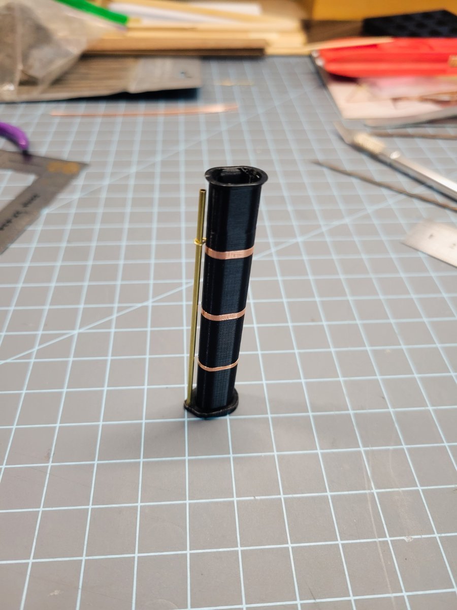
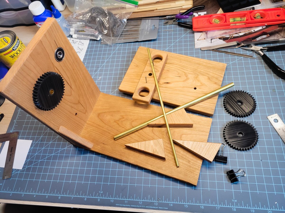
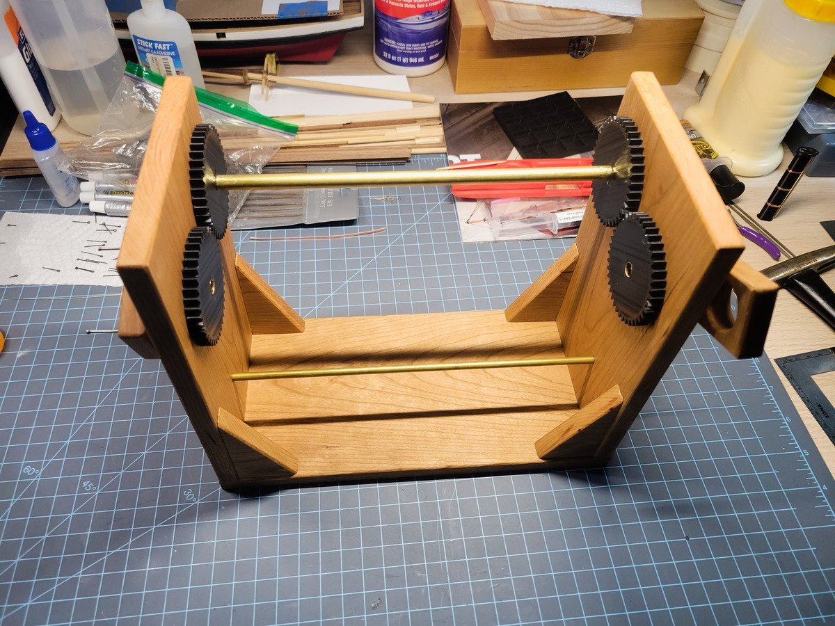
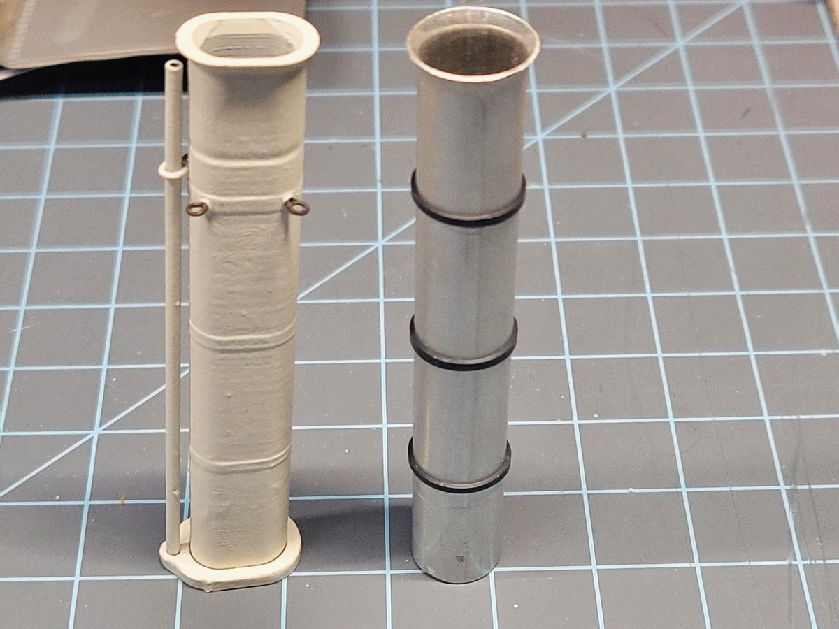
I spent some time yesterday and today building a copy of the Syren servo-matic machine because it looks cool as heck and I had everything on hand to build it. I also wanted to upgrade the gear shafts to include bearings I purchased many years ago and had to buy 10, but only used 2. I used 1/2" cherry and 3D printed the gears, after modeling the entire thing in Blender to get the measurements right. Full credit for the design goes to Syren though. Other details include a 5mm bobbin holder, and 8mm gear shafts. I don't have a scroll saw, so to make the handle I used some forstner bits. The gears are attached to the shafts with 5 minute epoxy, the same for the bearings to the wood. The shafts were pressed into the bearings using the lathe. I seem to be using it more to press stuff than turn anything lately! I didn't have washers that fit the 8mm rods, so I used a playing card cut to shape to provide a little standoff and so the gear isn't rubbing on the wood. Does it need bearings? Absolutely not. But is it cool? Yes! Next my attention turned to the engine funnel. I've been poring over expedition photos and keep noticing the shape of the funnel. It's a rounded rectangle, and the more I considered it the more I knew I'd want that shape. I spent an embarrassing amount of time trying to figure out how to shape the aluminum tubing into that rectangle while retaining the rounded corners. Then I thought, 3D printing it might work. I have an FDM printer (Ender 5 Pro), not resin, so there's a limit to how small I can print, and the flare at the top might be too small. I modeled the shape I thought looked similar to this picture and this picture and gave it a shot. Lo and behold, I think it worked out nicely. The base is also 3D printed. The bands are copper tape (slug repellent or doll house conductivity tape, same stuff) and the tube is a 1.5mm brass rod. I primed it with Vellejo surface primer, several coats. For the color I didn't want a "brand new" white so I mixed 10:1 Vellejo Model Air White and Vellejo Bone White. Then finished up with matte finish. Boy, zoomed in pics really bring out the lumps and bumps eh? Compared to the aluminum tube with heat shrink tubing I very much like the result of the new funnel. I'm not sure if it comes through in the pic, but it is raked back according to the OcCre plan. The eyebolts are soldered and blackened (assume every eyebolt shown from here on out is soldered and blackened). I'm missing the whistle, and I'm still considering what I can use to suggest it. Or I may leave it off. Thanks for reading!

-
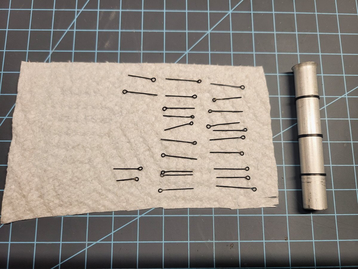
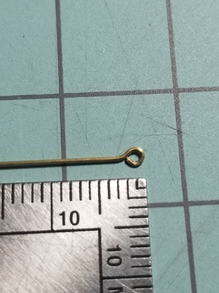
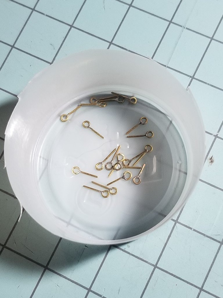
Thanks Keith, I appreciate you dropping in! I've been reading over your log and thoroughly enjoy the upgrades you've put in, which are inspiring me to go the same route. You've done a great job so far! The galley smokestack is definitely needed, so I'll be including that, thanks for confirming! While the Endurance kit is making its way towards me (should be late next week!) I decided to begin. First off, I found clearway's funnel and realized I just came across some aluminum stock that I accumulated at some point. Luckily OcCre's instructions for this kit are able to be downloaded from their website and I saw they have a 1:1 plan for the funnel. They say to use the included 12mm dowel, so I measured the aluminum tube and coincidentally enough it's 11.1mm. Not quite 12, but close enough to experiment with until the kit arrives. I took care of the flare by using the tail stock on a lathe to press a cone into the end, stopping once the size looked right. The bands are heat shrink tubing cut to 1mm (or so) wide and heated. Speaking of eye bolts, I'm deciding to hand make and blacken all 110 (according to the instructions, there may be more) that are needed. It's been a while since I've done this, so it was slow going at first but speed picked up and quality improved. I detailed how I do this in my Newport log, here. It's a tedious task, but I absolutely love the look of enclosed eyes, and they're mostly enjoyable to make. It should also add to the security of the rigging as well. As for blackening, I plan on painting the hull a weathered black (no anti-fouling paint) and I think blackening the eye bolts would really blend into the color scheme (along with blackened 0.5mm rod for ratlines). The long bolts will be used for placement on the decks with the tails bent and secured underneath, as suggested in other logs. I'm not going to make all of them in one go, but rather here and there while taking breaks on planking, or decking, or whatever. Thanks for stopping by!
-
Thanks for stopping by Johnny, I've seen your vast knowledge strewn across several Endurance logs and am happy you have found your way to mine as well. Hmm, a decision will need to be made then as I really do want the steering gear to be exposed. Perhaps this falls into the 10% that's not particularly accurate! I have been googling Frank Hurley's Endurance photos for several days now and have put together a folder of reference material. Including the under water footage from last year. You're right: it can be difficult placing the photos to a particular stop in the trip. This will be where my need for historical accuracy will diminish and some artistic freedoms will probably be taken.
-
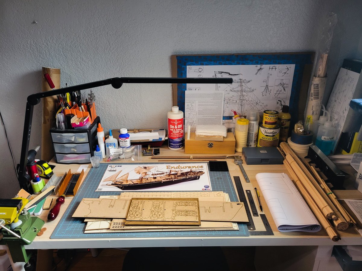
Hello MSW! This post serves as an introduction to yet another build log for the Endurance kit by Occre. First, a little about me: I started this wonderful hobby as a teenager and kept at it when I could as I was traveling all over for the US military. This made it difficult to set up a permanent workshop (or table as it were) so my first and second ships stayed on standby for most of this time, with small bursts of productivity here and there. Unfortunately, the San Fran in my signature was lost to rough handling by a shipping company (yay army movers!) many many years ago, when I got out of the military. The Newport is currently on my newly-setup work table and I have been making slow progress with it and will need to update that log soon. I've built a dinghy and a skipjack on the side, which I don't necessarily count as "wooden model ships" in the class these vessels are in. That being said this kit will be my 3rd model ship kit. Anyway, we're here to log my rendition of the famous Endurance. She needs absolutely no introduction, and I'm going to point anyone who wants more information to the numerous and great build logs from others, as they've done a remarkable job documenting the ship's beginnings in their logs. First thing is first, my kit is currently in the mail on its way to me. While waiting for the kit to arrive I have already read through every Endurance log on this website and will probably read them all again for good measure. While making my way through the logs I took note of every bash and scratch build people have done to make this model more historically accurate. I'm not going for 100% accuracy, but perhaps somewhere around 90% accurate, to the extent my modeling skills allow. There was great advice given to focus on a particular 'load out' as this ship seemed to change a little here, a little there over the course of her voyage. I am particular drawn to the very beginnings of being stuck in the floes, so I imagine I will gravitate towards this set-up. I don't have all of the details nailed down yet in my notes for this period of the voyage, but over the next few weeks as I work on the obvious structures, I'll continue research and make decisions as we go. Things I already plan on changing (so far): Under the forward deck will be open (I have a question on this at the end of this post). All belaying pins replaced with brass. Stanchions will be 3D brass with brass wire rod, soldered then painted white. 2-Blade brass prop (someone in another forum said it was 25mm. I could only find 30mm, so I hope it's not too big). Coal loading covers instead of the o1 stacks on the aft main (lower?) deck. Probably scratch capstan. Steering gear with chain (thread as backup). Anchor cats shaved down towards deck. Deck planks 2.9mm wide (for 8" planks). Portholes are too small, so either fill and drill new or drill bigger (and not using the brass inserts). I'm sure I'm missing something else but you get the idea. That sums up where I currently am at: the very beginning. I've always enjoyed curating a log on these forums and is why I keep coming back after so much time has passed. I appreciate anyone and everyone stopping by and offering suggestions, thoughts, concerns, and motivation. Please feel free to post any historical data you might have that's relevant to the ship's configuration as she entered the ice floes. I'd be eternally grateful! I have a few questions to start off with: - Area under the anchor deck. What was it used for? What did it look like? Are there any images that show this area? @Tomculb has a great interpretation of this at this post, and I'm inclined to do the same. - In this picture it appears the ritz has a chimney coming from the port forward side. Is that correct? If so, I'll be including it in my model. - Was the steering gear exposed when they first entered the ice floes? OcCre has it covered, but I want to model it. However, since I'm going for a particular time in her voyage, I'm not sure if it was covered in the beginning of the floes or not. Until next time! --------------------------------------------------------------- Edit 3/31/24 - Over the course of this project I have created a handful of .STL models that can be 3D printed which replaces some of the items in the kit. I'm editing this post and including a link so it can be found easier by anyone building this kit in the future. Click here.
-
Short and sweet update this morning. Finished the breeching ropes for the cannons.
-
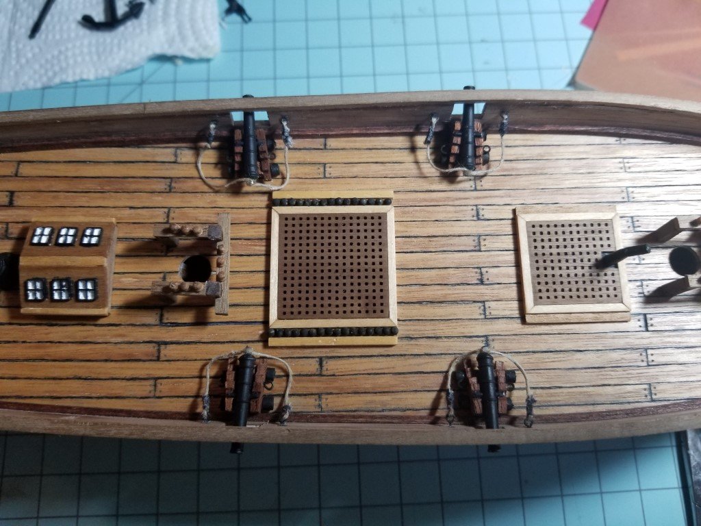
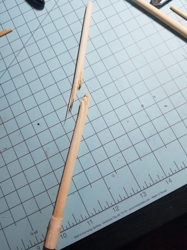
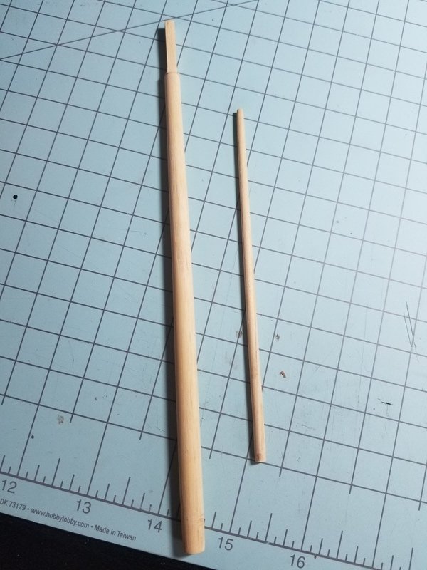
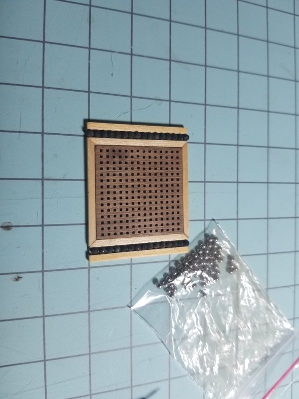
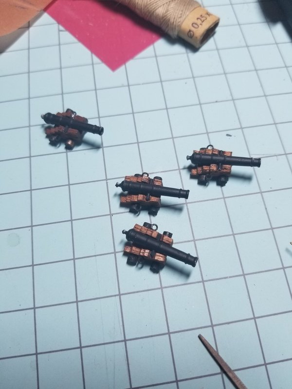
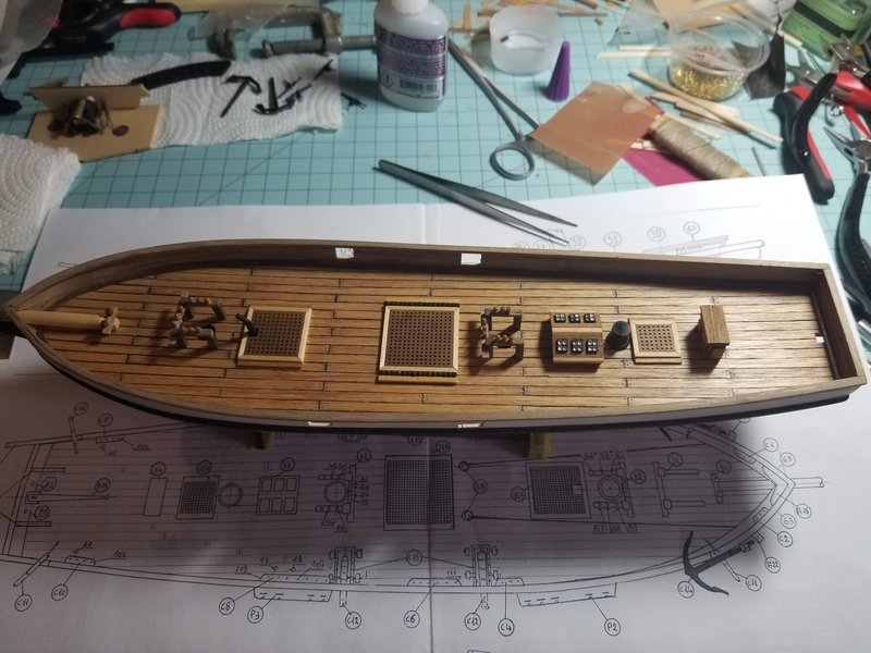
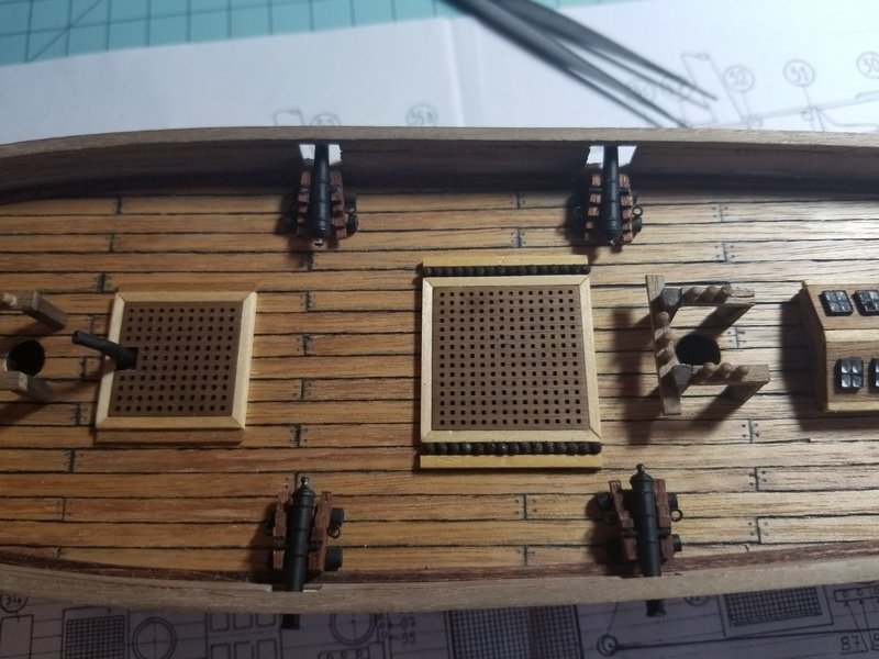
Hi everyone. Rather large picture update today, so let's get right to it. First up is the fact that I somehow destroyed the main mast. Yeah, the main one. I was tapering it last night when it just seemingly shattered in my hands. I'm chalking it up to old kit wood, so I'm going to order a new 8mm dowel this week along with some 2mm x 2mm ramin to finish off the crosstrees. Because, you know, this kit didn't come with everything I need. I finished the forward mast tapering, and I'm super proud of it. On the San Fran, that square portion is uneven and weird looking. On this one, it's as perfect as it can be. Finished the cross tree and the cheeks. I just need to paint it, now. I'm going to hold off painting it until I have more stuff to paint. I got a hold of some "Mary Kate On and Off" bottom cleaner from work. It's made of Hydrochloric Acid, along with other acids, so it should do a better job with the Brass Black adhering. The cannon shot is 2mm stainless steel ball bearings. The black rubs off a bit, because I'm not polishing the balls, but it still looks fine as it is. The main grate is complete. Glued in the cannons to the scratch-made carriages. I've decided rigging them is more trouble than it's worth, so I'll just be adding some breeching ropes and that's it. I'm also not going to lay the brass strip over the top like I talked about before. Main grate is glued down on to the deck. It's not exactly where it needs to be, but it'll work. I also dry-fit the cannons to see what kind of space I'm working with. They aren't glued down yet, so I'll be marking 2 places on the bulwarks for each cannon's breeching ropes. Then drilling a hole for the eye bolts, installing them, then rigging up the breeching ropes.
-
Hello all. Not a very big update at all today. I blackened the eyebolts I made in the last post, and installed them on the cannon carriages. I'm having a big issue with the black not "sticking" on the brass. If I touch them with my fingers, it rubs off quite a bit and looks splotchy and bad. Using tweezers isn't nearly as bad, so I had to do some finer handling of these to make sure they stay black. I'm definitely worried about tying rigging blocks to the eyes, because the thread very well could pull all the black off if I move it too much. Does anyone know why this is the case? I also airbrushed grey primer on the cannons themselves, and then airbrushed on black. The result isn't that great, because they're so small. I may try to coat them with black again to cover up some of the spots, or I may try to brush on some paint just to touch them up. We'll see. Tonight I plan on strictly shaping the masts and yards, now that I have some lower grit sand paper. I should also be receiving my 2x3 walnut strips, so I can finish working on the pin racks and other deck fittings.
-
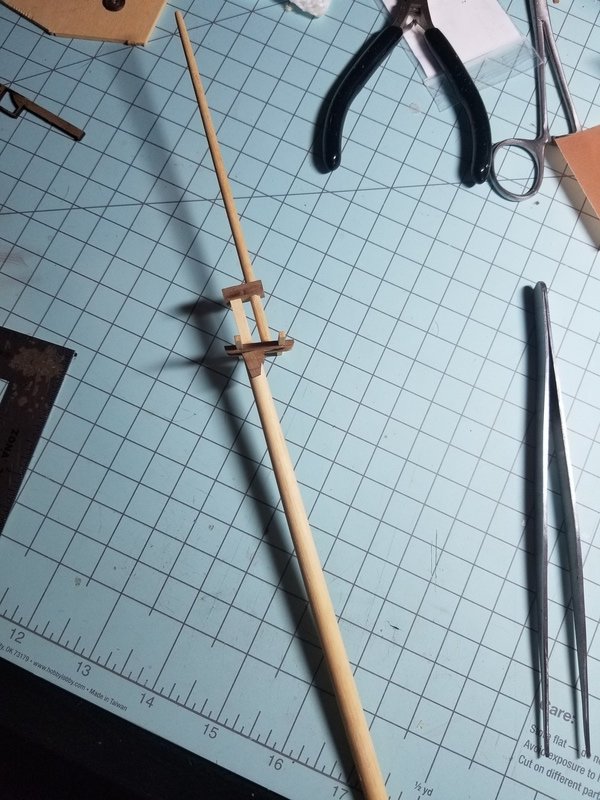
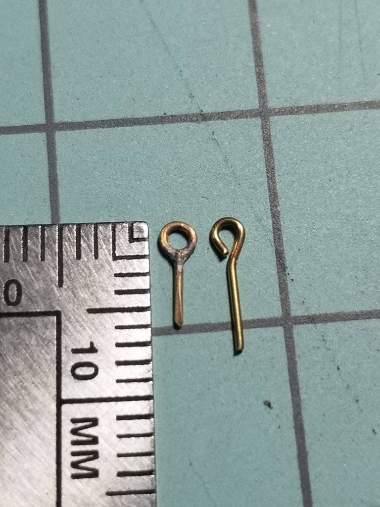
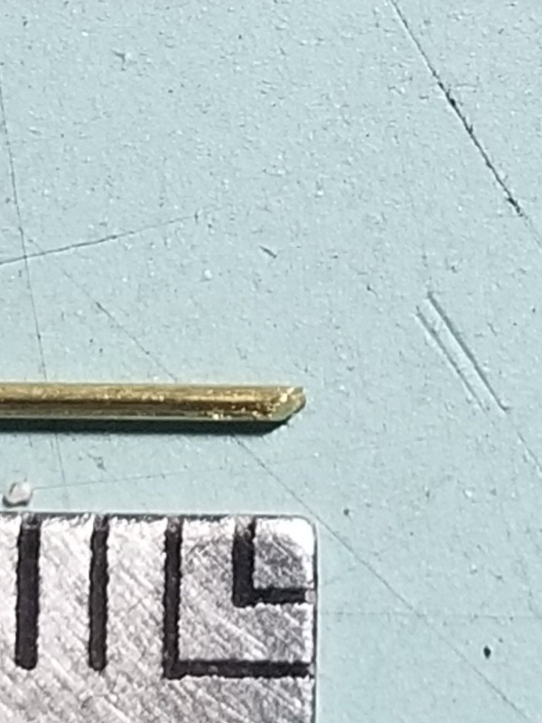
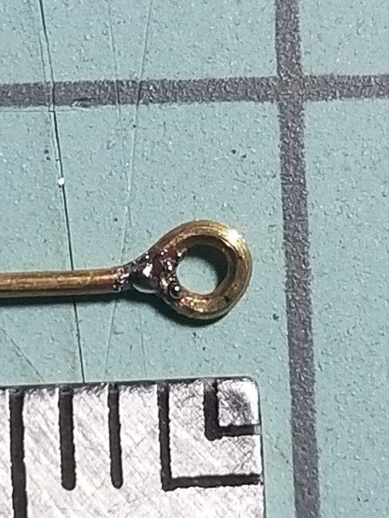
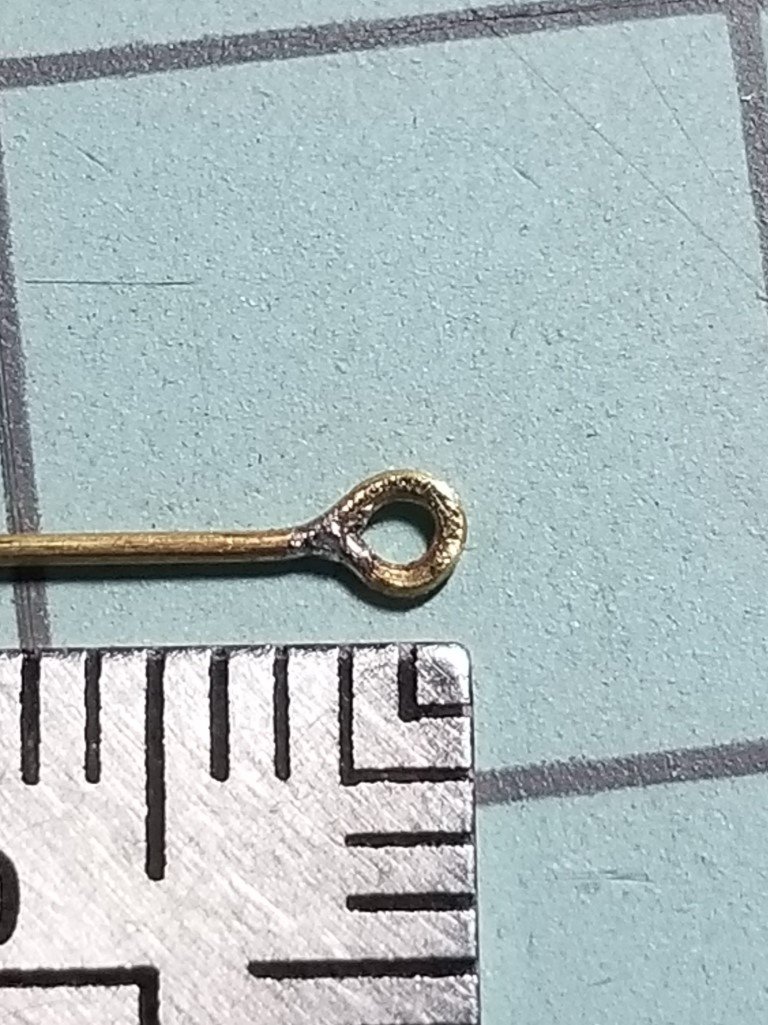
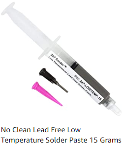
I have to admit I was a bit worried about the silver soldering aspect, and creating eye bolts from scratch. Turns out, it's incredibly easy to do with the proper tools. I couldn't find a solid "How to make eyebolts" tutorial, so I'm going to create a small one here to hopefully help anyone else that is intimidated by doing this. ***Disclaimer: Please be careful when using a butane torch next to wood! Especially wood that's had lacquer applied to it, or other flammable substances. You should perform this work in a well ventilated area, making sure there are no chemical fumes present that can be ignited by the torch. This post is meant as a guide only, not a step-by-step process. Please be safe! Tools Needed for Silver Soldering Brass Eye Bolts Silver Solder Paste (I got the pre-fluxed kind, along with lead and cadmium free. Picture of this is below.) 0.5mm diameter brass rod Third Hand with Magnifying Glass (something to hold the work while you apply the heat) Butane torch (the one I use is a hand-held torch for lighting cigars, etc) Small hand files. Specifically 2mm round file and 3mm flat file. These came in a kit of 10 or so different shapes. Small round-nose pliers. Found in arts/craft stores in the jewelry making section. Needle nose pliers. *Important: Make sure they do NOT have serrations in the jaws. This will create artifacts on your work, which you don't want. Sanding stick (150g paper glued to a wooden block is what I have) Diagonal side cutters First I'll start by showing the end result vs. the kit supplied eye bolts. The first thing I did to achieve the above result is to cut a 10cm piece of brass rod with the diagonal side cutters and drag it between my finger and the sanding stick. This removes any coating on the brass, and preps the surface. Make sure to drag it through several times, while turning the rod. This gets it from every angle. Using the 3mm flat file, I file the one end of the rod flat. Pictures do the better talking here. The below pic is before sanding this end square. The next pic is after sanding the end square. See the difference? Using the round nose pliers, I create the eye. It's very difficult to explain what I did here, but keep in mind that brass is somewhat springy, and wants to go back into the shape that it was initially. You have to over-bend a little bit, to make sure you butt up the cut end to the shaft of the eye, creating the round shape. You want the end touching, as close as you can, the shaft. If there's a hair gap, that might be okay, but you really do want them to touch together. Using the needle-nose pliers that don't have the serrations in the jaw, I shape the eye bolt to be completely flat, as perfect as I can get it. Notice in the above picture, the end that was filed square is sitting flush on the shaft itself. If you don't file the end square, there's less surface area for the solder to adhere to. Next, I stick the rod in my Third Hand. It's time to apply the solder. The above is what I purchased. I place a BB size drop on a piece of spare wood, and use a tooth pick to apply the smallest drop to BOTH sides of the eye bolt. You want the solder to be encompassing the entire connection there where the shaft touches the end that you filed down. This is something you're going to have to experiment with. Too much solder, and when you go to sand it down you may break the connection and have to start all over. Too little solder and you won't hide that junction very well, so it won't look like a solid piece of metal. Double check your work space can accommodate an open flame, and turn on the torch once you believe it's safe to do so. I start the flame around 8" away from the work piece, and move it closer. I'm watching the solder through the magnifying glass, and as soon as it turns into a liquid I back the flame off and turn off the torch. This takes around 2 total seconds to complete, once you know what you're looking for. The solder will flow around the work, and that's when I stop the heat and turn it off. I'm left with the result below. It's a bit bubbly, so I use the 3mm hand file to file down both sides. Then I use the 2mm round file and get the hole filed down towards the junction, along with the anything else that can be cleaned up. After filing, I'm left with the below picture. The close-up reveals some tool marks, which you want to avoid if you can. However, once they're blackened, I don't believe the marks will be visible. Certainly not from outside of a display case anyway! I created a small jig so I can quickly cut 8mm from the top of the eye bolt, which produces a perfect result. In the beginning, it took around 15 minutes to make 1 eye bolt. Towards the end of my session, I could complete 1 in around 6-7 minutes. It was enjoyable for me, and I have a ton more to make. But, this is how I did it, and I hope it can help anyone else!

-
Another small update today. Finished the two mast belaying pin racks, which were a pain in the butt. Each pin's shaft had to be sanded down to fit into the holes I drilled. It's not my proudest work, but, it'll do. Also glued most of the fittings to the deck. Completed the chimney as well. It's currently sitting in grey primer, and I'll finish painting it black tonight. I painted grey primer on all of the metal parts, as they're all getting painted black. I'll have the black applied tonight I imagine. I also submitted an order for some new 2x3mm walnut strips, as my kit definitely doesn't have enough to finish all of the pin racks. I received my silver solder yesterday, and the Casey blackening solution arrives today. With all of that, I can start working on blackening some eye bolts, and installing the cannon carriages. I have some spare brass sheet from the chain plates (which are a completely wrong size as it is for the dead eyes supplied with this kit. Not sure what I'm going to do there, but, I'm not there yet.) so I'll cut and blacken some straps to hold the cannons down to the carriages as opposed to just gluing them in. Lastly, I don't have the main grate glued in yet as I have some 2mm ball bearings on the way. I'm going to attempt to blacken them, but I'm not sure how it'll work with the bearings being stainless steel. If anything, I'll just paint them black via brush and some enamel paint. Once that's done and glued into the main grate, I'll get the grate glued in.

-
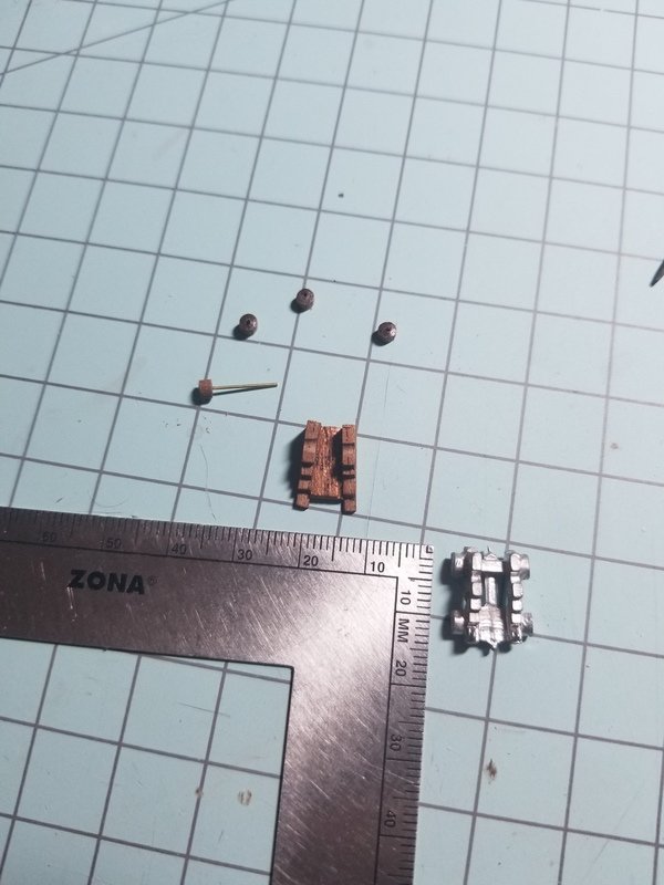
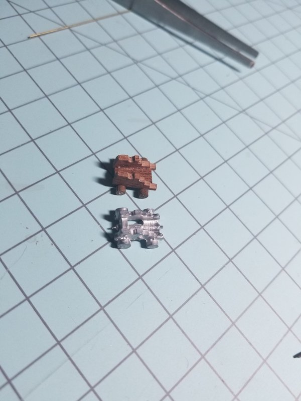
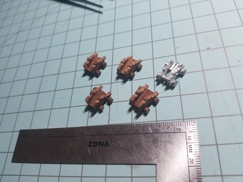
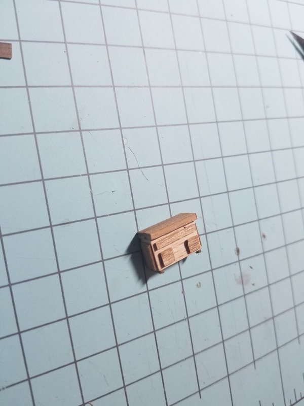
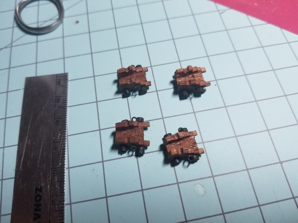
Big picture update today. Finished most of the deck fittings, but haven't glued anything down yet. Made carriage wheels with 3mm dowel and brass rod. Finished 1 carriage. All 4 carriages made. Finished the drawer. Decided that the cannon carriage wheels needed to be black. Received some amazing rigging blocks from Chuck. You can see the poor quality kit supplied blocks. Finished the deck grates as well, and applied tung oil to everything.