TonyM
-
Posts
49 -
Joined
-
Last visited
Content Type
Profiles
Forums
Gallery
Events
Everything posted by TonyM
-
 Waldemar, your work is very inspirational. The way your model is presented as illustrations with cutaways is very effective and perspective gives that sense of depth. The combination of nautical research and digital modeling is particularly interesting and I wonder if you have thought of a digital representation such as Sketchfab. I have done a simple CAD model "Schooner Adventure" with a build log on MSW and a viewable 3D rendering on SketchFab Schooner Adventure In the meantime I am working on the next model in Fusion 360 with CAD timber components and your work gives me a lot to think about.
 -
Exploring FreeCAD for ship modeling
TonyM replied to TonyM's topic in CAD and 3D Modelling/Drafting Plans with Software
Really nice work Pat. I am thinking of moving from FreeCad to Fusion 360 which would end my commitment to this topic. The export functions difficulty was the driving reason. I am exporting in STEP then converting to .GLB to load into Sketchfab. There are no texture files but the material comes across with color but not all the rendering parameters such as shininess. This required a lot of editing in Sketchfab which recognizes material by color only. The Light field device from Looking Glass Factory worked and the .GLB file was loaded into a studio software and 3D views were generated to load into the display device called Portrait. It provides a 3D presentation with parallax and stereoscopic simulation so that the model looks real inside the "case". -
Exploring FreeCAD for ship modeling
TonyM replied to TonyM's topic in CAD and 3D Modelling/Drafting Plans with Software
Some time has passed since my last post. I have rethought the rope construction which although successful was very expensive digitally when generating the rendered image which now can be loaded online at SketchFab. The model is almost complete with some more running rigging to complete and I will switch attention to the displaying of 3D models. The flat screen rendering is not very exciting and there is some new technology called "Light Field" display which I will research in the new year. It apparently gives a stereoscopic illusion using a special display screen. I will update the forum when I have more experience of this technology.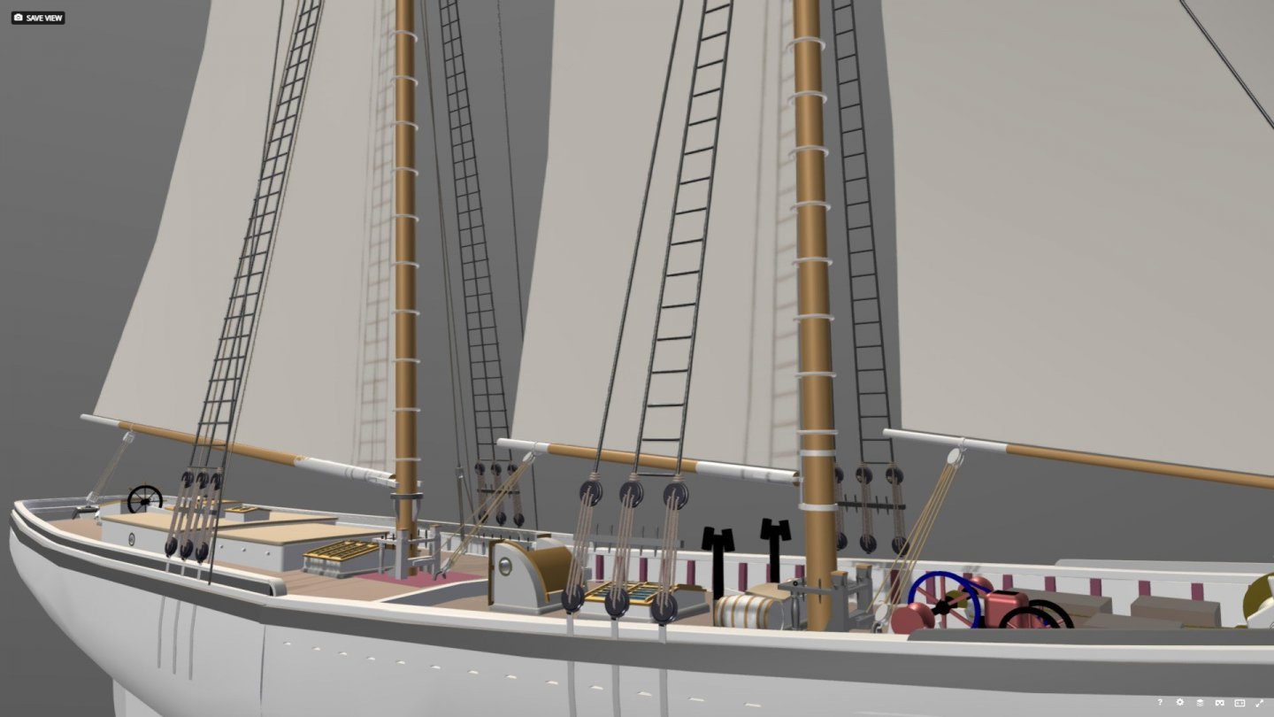
-
Exploring FreeCAD for ship modeling
TonyM replied to TonyM's topic in CAD and 3D Modelling/Drafting Plans with Software
So I decided to fully rig the schooner since the display mechanism seems to be Sketchfab and my first attempts were quite encouraging. The process was a bit tedious and involved exporting the model from FreeCAD in STEP then transforming it to .glb to load into Sketchfab. When I make the image public on Sketchfab I will reference it in the posts. The rigging seemed to need sails so there is some exploration work to deal with surfaces in 3 dimensions and the projection of seams onto the curved sails. This is exposing challenges such as the geometry of the leaches (which are all straight at the moment) along with the angle of the gaffs, booms and sails to the centerline (which are also straight at the moment). Obviously this is just a rough setup which will give me an idea of what is possible but progress in happening.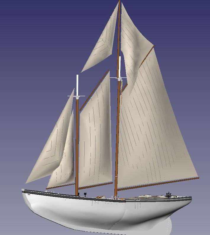
-
Exploring FreeCAD for ship modeling
TonyM replied to TonyM's topic in CAD and 3D Modelling/Drafting Plans with Software
Thanks Terry, Actually it s not as bad as it looks. I have segments of straight rope that I fuse together and half circles which were cut from the ring earlier in this post. It is still a bit rough and there is some discoloration which I will fix but the idea is to have rope components that I can assemble. Tony -
Exploring FreeCAD for ship modeling
TonyM replied to TonyM's topic in CAD and 3D Modelling/Drafting Plans with Software
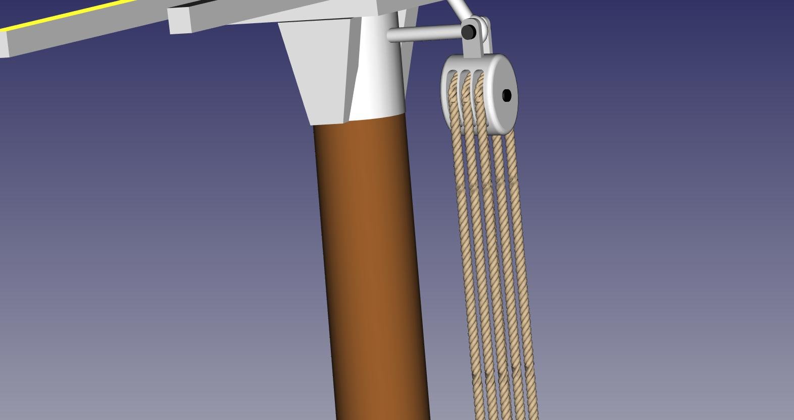
Sorry about the delay in responding to Sailor and Dane. Sailor - Yes the tuck was around 8 oclock and was not pretty. I can probably work to improve it but the ring was just to explore the method which was difficult. Dane - yes it is done from 3 strands. I have an easy method for a straight rope which is to form a polar array of 3 helixes and then sweep a circle of each strand cross section along each helix. The curved rope (shown as a ring) is done by creating a polar array of triangles and 3D splines are woven through the points of each triangle forming 3D helixes around the array of triangles. Then I sweep the strand cross section along the splines. Very time consuming and I want to find a better way. The purpose of the circular rope is to feed it through a block. Here is a fragment of the schooner with the main upper throat block.
-
Exploring FreeCAD for ship modeling
TonyM replied to TonyM's topic in CAD and 3D Modelling/Drafting Plans with Software
Here is a rope grommet built up from 3 strands.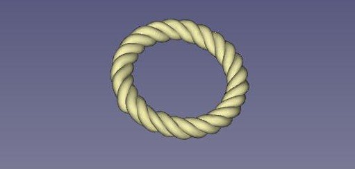
-
Exploring FreeCAD for ship modeling
TonyM replied to TonyM's topic in CAD and 3D Modelling/Drafting Plans with Software
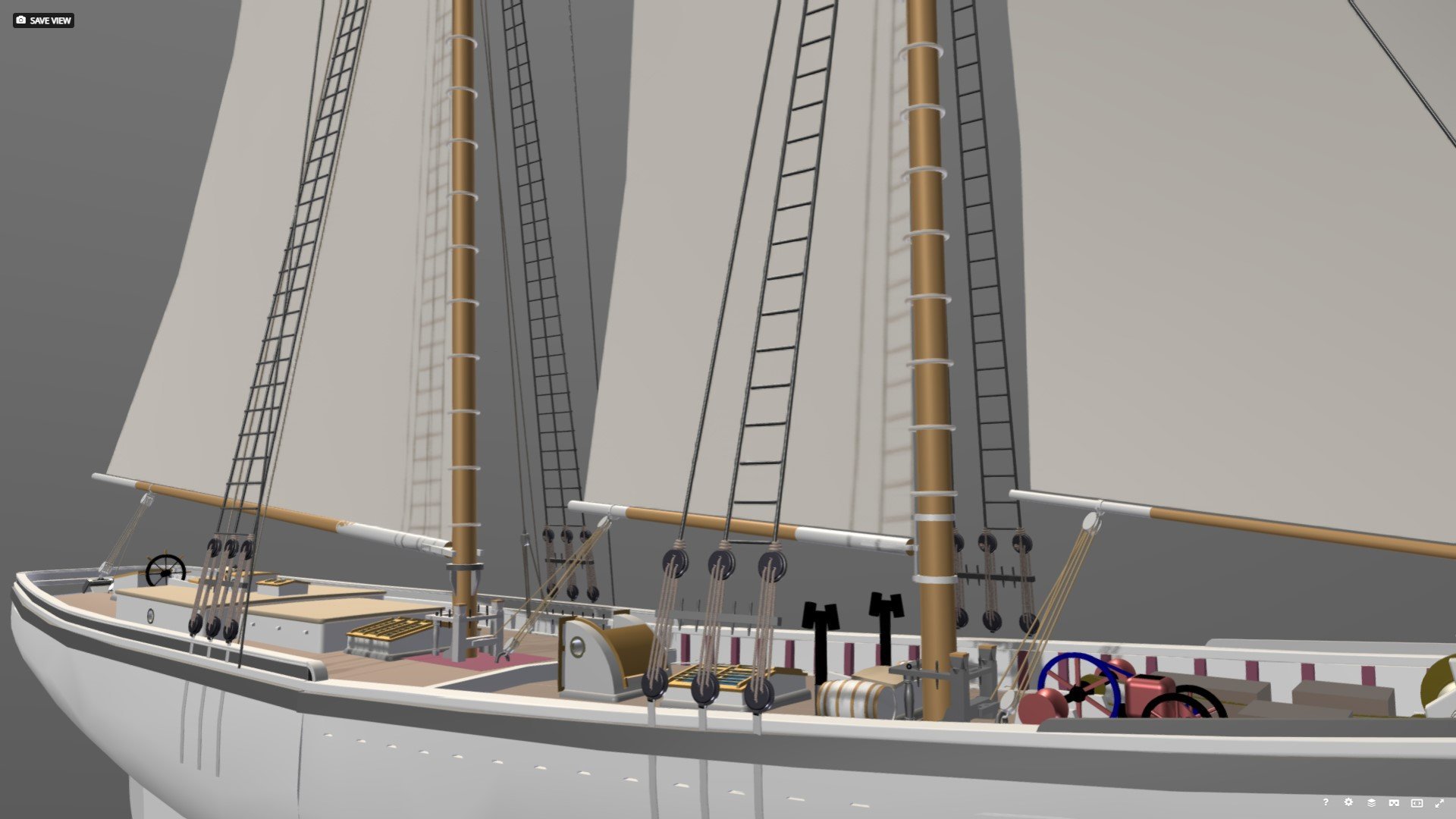
Here is a view of the latest state of the model. Some challenging items are to get the deck seams looking right. Although this is not the finest resolution image, belaying pins are just visible on the main Fife Rail.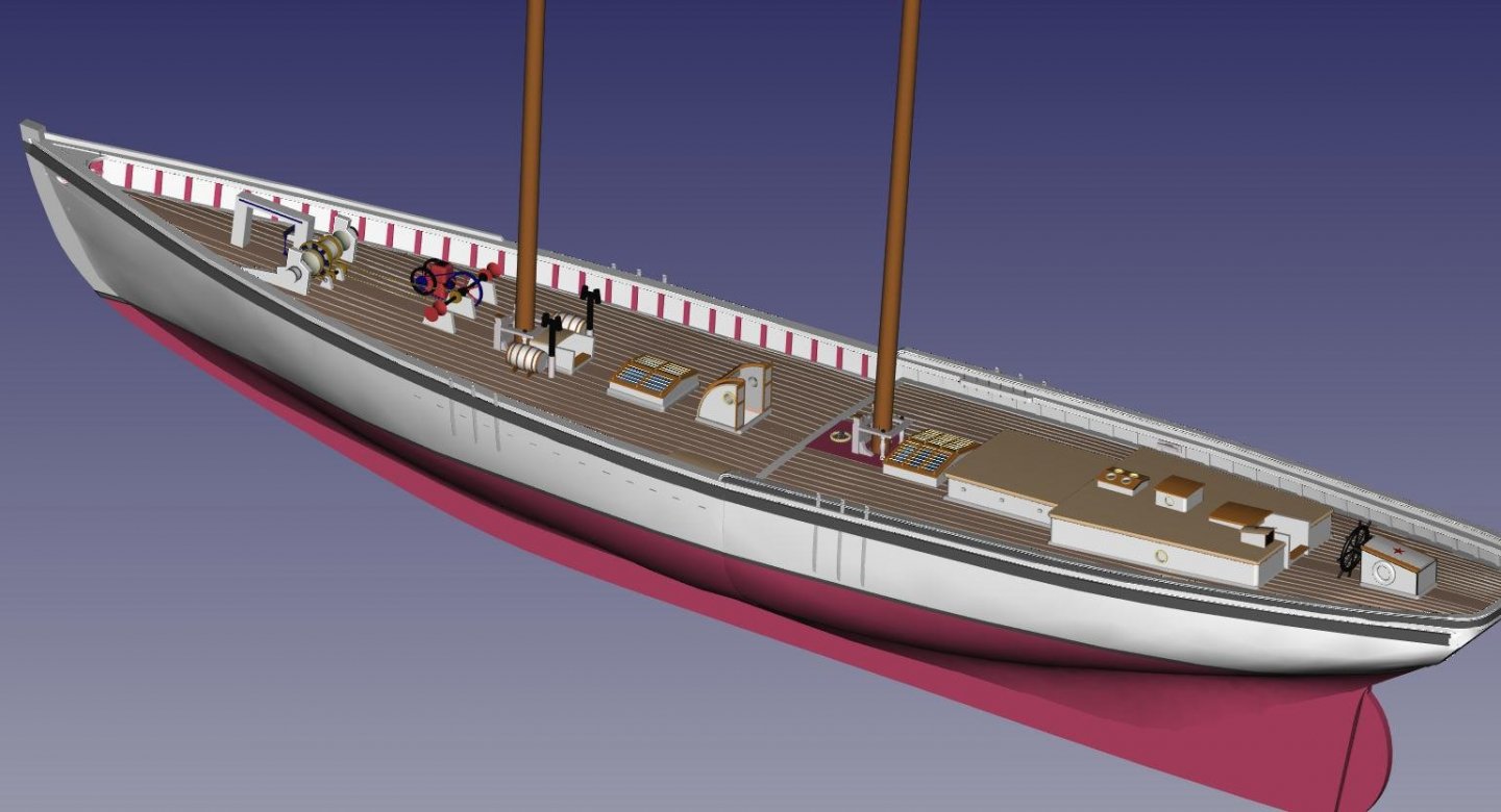
-
Exploring FreeCAD for ship modeling
TonyM replied to TonyM's topic in CAD and 3D Modelling/Drafting Plans with Software
Thanks SteveWTI, I have not had a problem with speed. The model is now about 30 Mb in its FreeCAD format and if it does a complete recalc takes about 10 secs. In most cases a complete recalc is not needed and it is fast. No I did not do any Python work it was all straight GUI. The size of the model has increased dramatically because I am playing around with rope in 3D and it is very data intensive. I will post a new image of the model with a whole lot of deck furniture done. -
Blender startup for ship design
TonyM replied to edbardet's topic in CAD and 3D Modelling/Drafting Plans with Software
Ed, I am using FreeCAD to build the 3D model and have just started importing it into Blender using .wrl. See my other posts on FreeCAD. Most of the model seems to be there but I am struggling with the representation of parts and surfaces in Blender. It recogizes parts but seems to need splitting of surfaces if the surfaces have a different material. If anybody has experience it would be greatly appreciated. Tony -
Exploring FreeCAD for ship modeling
TonyM replied to TonyM's topic in CAD and 3D Modelling/Drafting Plans with Software
Thought I would post the latest developments on my Schooner. The next addition has been the stanchions which are built using a solid loft along templates housed in the bulwark part of each station. This solid representes the KnightHeads and Hawsepieces at the bow and then is cut using a cutting solid into the distinct stanchions. I do one set for the main deck and one for the quarter deck. I have colored then red to distinguish. At the bow I cut the Hawse pipe through the Hawse pieces and the hull. The next to be added was the monkey rail which wraps round the transom as the taffrail. This is the first attempt and is quite difficult. I will probably rework this soon. The seat as an extension of the main cap is not shaped correctly yet.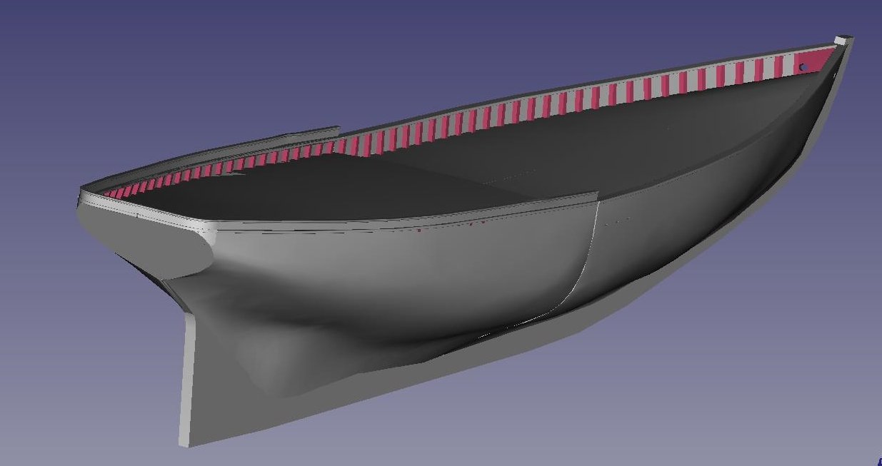
-
Exploring FreeCAD for ship modeling
TonyM replied to TonyM's topic in CAD and 3D Modelling/Drafting Plans with Software
Kris, Some of this work was done before I joined the forum and has just needed to be refactored for the changes. So it is not as fast as it appears. -
Exploring FreeCAD for ship modeling
TonyM replied to TonyM's topic in CAD and 3D Modelling/Drafting Plans with Software
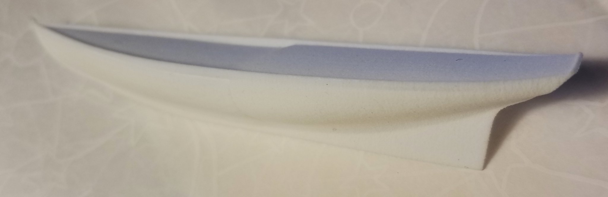
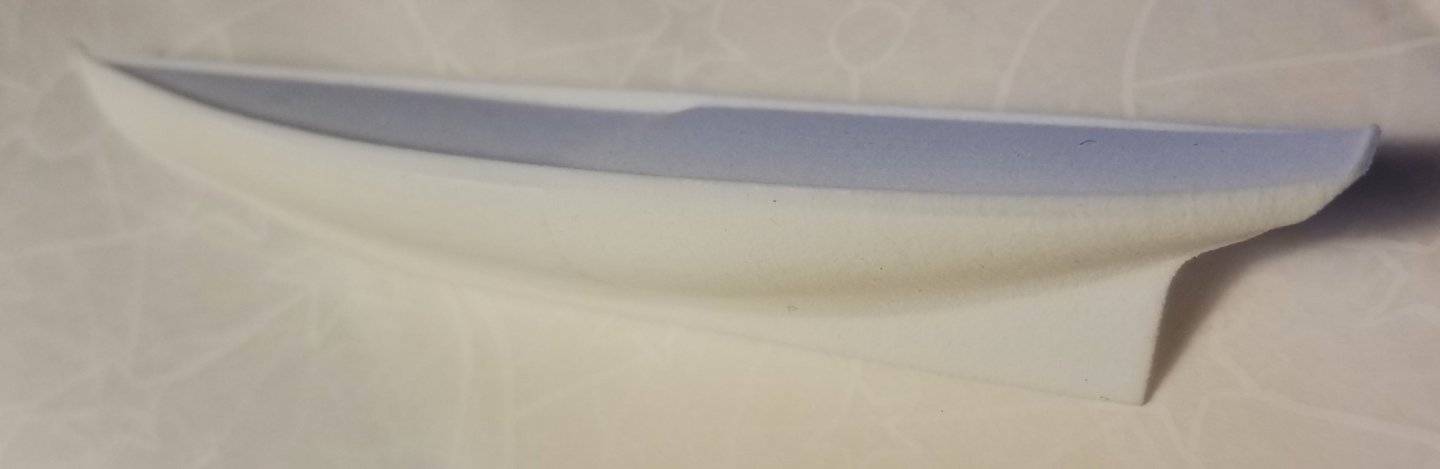
It is probably time to discuss intention. I had started with some ideas in mind like building the real model in wood but the more I explored the topic which is quite well covered in this forum, the more I realized there are other possibilities such as creating a realistic image or generating a 3D printed model. I had not shown the surface generation which was done to create the waterlines by lofting the stations. The lofting was done in two parts - the forward main deck and the quarterdeck due to the disruption of the step. Both parts are then mirrored to get the port half. In hindsight it might be better to separate the generation of the decks but doing it this way is easier since the deck positioning is defined in the frame sketches. There is some disagreement between the rabet at the stern and the decision of the FreeCAD lofting operation but it is expected. This can be corrected if necessary with an additional station just forward of the rudder and extend the next station down to the rabet. As this has been exploration, I tested out 3D printing with Shapeways on a smaller version by scaling down at time of printing. The file exchange went quite well and the model appeared in their Shapeways online viewer tool. I then ordered a print in the cheapest possible material just to see what would happen. This was an earlier version of the model. Not a very good photograph but there is not much detail to show. All the flaws in the model are faithfully reproduced. Some of my original iseas were to create plugs to build ships boats. It seems that you can build jigs and plugs quite easily and are not part of the finished model. I also thought about building the frames by 3D printing and then finish by planking in wood - a hybrid approach. In the meantime there is a lot more detail to create.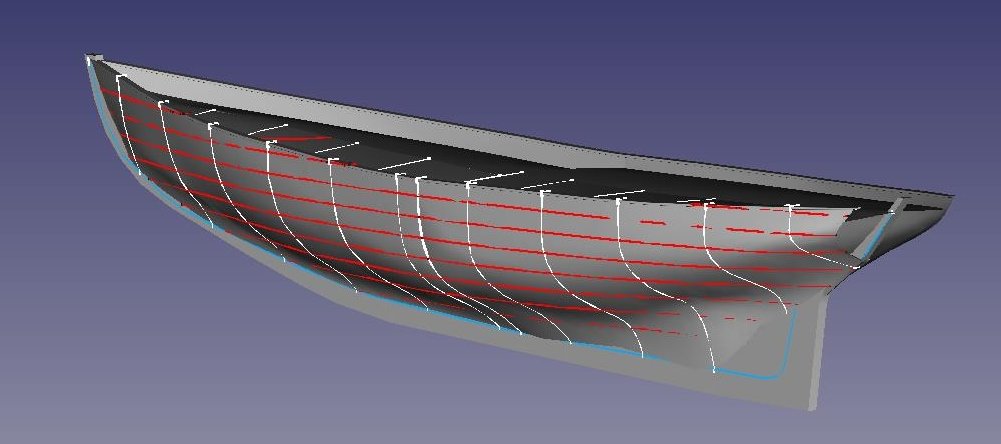
-
Exploring FreeCAD for ship modeling
TonyM replied to TonyM's topic in CAD and 3D Modelling/Drafting Plans with Software
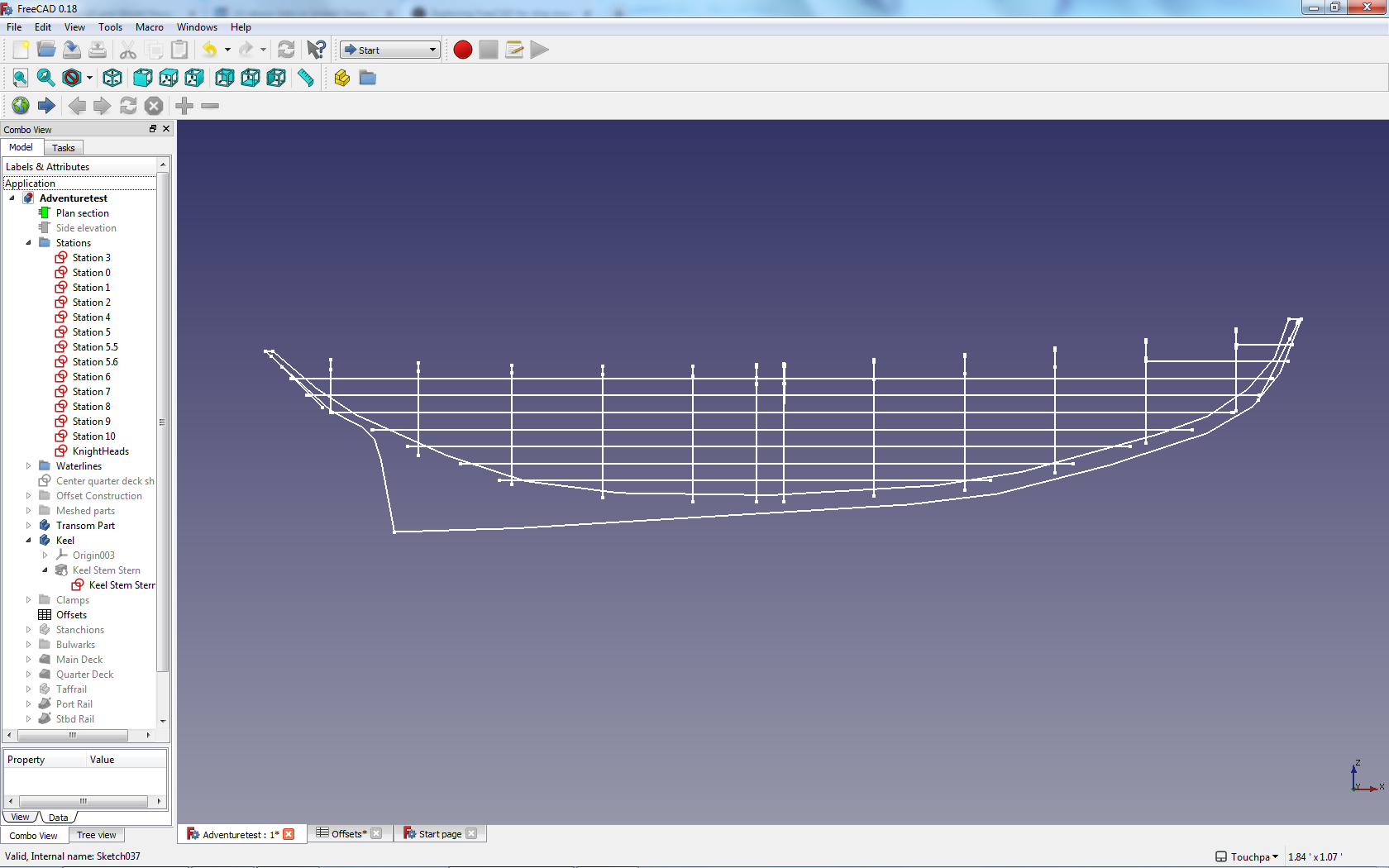
Trying to catch up on these good ideas. Firstly, I have reduced the model to a half hull (port) and tested the mirroring of it to a whole hull. As I thought, there are problems with the decks which are lofted along with the stations and do not intersect correctly at the center line. The crown of the decking is controlled through the station splines and perpendicular constraints are not allowed on splines. However the symetry is much better. I took Phil's approach to generating the waterlines (shown in red below) by creating a plane for each level and intersecting them with the hull surface which is lofted from the stations. This means that I don't have to worry about getting the offsets for the waterlines to be the same as the stations - it will generate them automatically. As a result of this I can go back to manual editing the stations against the original plans. The offsets are read from the stations and pulled into a spreadsheet for ease of examination. As expected, there are some irregularities showing in the waterlines and I will examine them and correct the stations. I did pay some attentin to the rabets which are drawn in blue and are projected off the centerline to still show when the keel is extruded. The rabets determine the lower ends of the stations which are represented by the bottom of the frame floors. I also developed a guidance line for the crown of the deck at the midsection to start to get the deck camber correct - still in progress.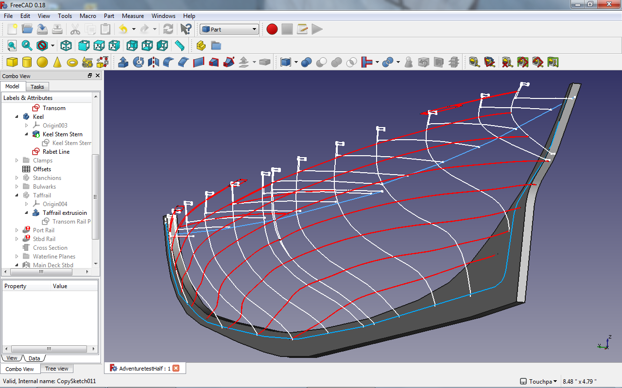
-
Exploring FreeCAD for ship modeling
TonyM replied to TonyM's topic in CAD and 3D Modelling/Drafting Plans with Software
Thanks Kris - I will get to your approach which looks interesting. Dr PR - thanks for the insight on getting the visuals of good fairing. I have tried this in a limited scope on my model and it is very revealing. The sample is the result of the LWL plane rectangle which has been extruded to a solid of 10 thou and then intersected with the lofted skin from the forward stations to form a line (red) running perfectly through the station points at the LWL. You can then examine the line and make corrections. (I haven't tested your correction mechanism). I plan to add these to all the waterlines after reducing the model to a half hull as recommended. From a first inspection I can now see that the symetry is not there building it as a whole hull.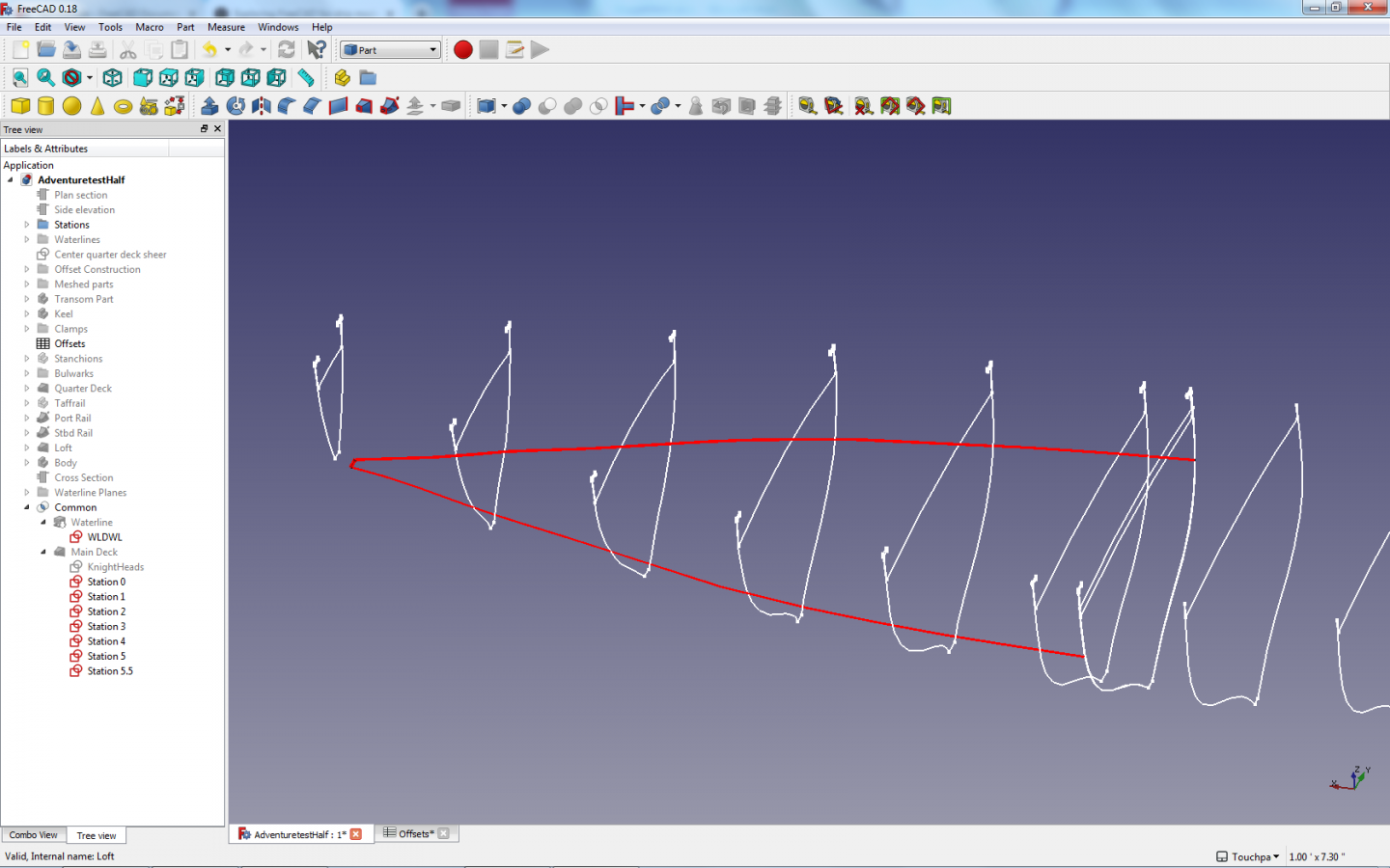
-
Exploring FreeCAD for ship modeling
TonyM replied to TonyM's topic in CAD and 3D Modelling/Drafting Plans with Software
Thanks vaddoc, I could go either way on the half or full hull. I will try the half hull approach since it is just a subset of the process. For the joint of the two mirrored parts constraints would be required - obviously the deck camber must be perpendicular to the middle axis. I forgot to mention the keel. The keel, stem and stern post were modeled as one piece but rabets were not drawn which would be a big improvement. I had eyeballed the intersection of the station lines to the keel but this should be to the outside of the rabet. The lines that I got were taken from the real schooner so I expect them to be to the outside of the planking which is the boundary for the 3D model. Drawing the rabet would give me offsets for the station outside plank when it meets the keel. The transom was sketched the same way as stations but with an angled plane. The outside of the planking is lofted to the outside of the transom wireframe which I will show in the next stage. The stem has a sort of knighthead pair which carry the planking line rather than a rabet - not very elegant and needs improvement. There is no thickness to the planking and I will loft to a solid hull which will have a cavity. The internals are not visible in the model. Here is the view of the stations and waterlines with the ends clearly visibible. This definitiley needs improvement.
-
Exploring FreeCAD for ship modeling
TonyM replied to TonyM's topic in CAD and 3D Modelling/Drafting Plans with Software
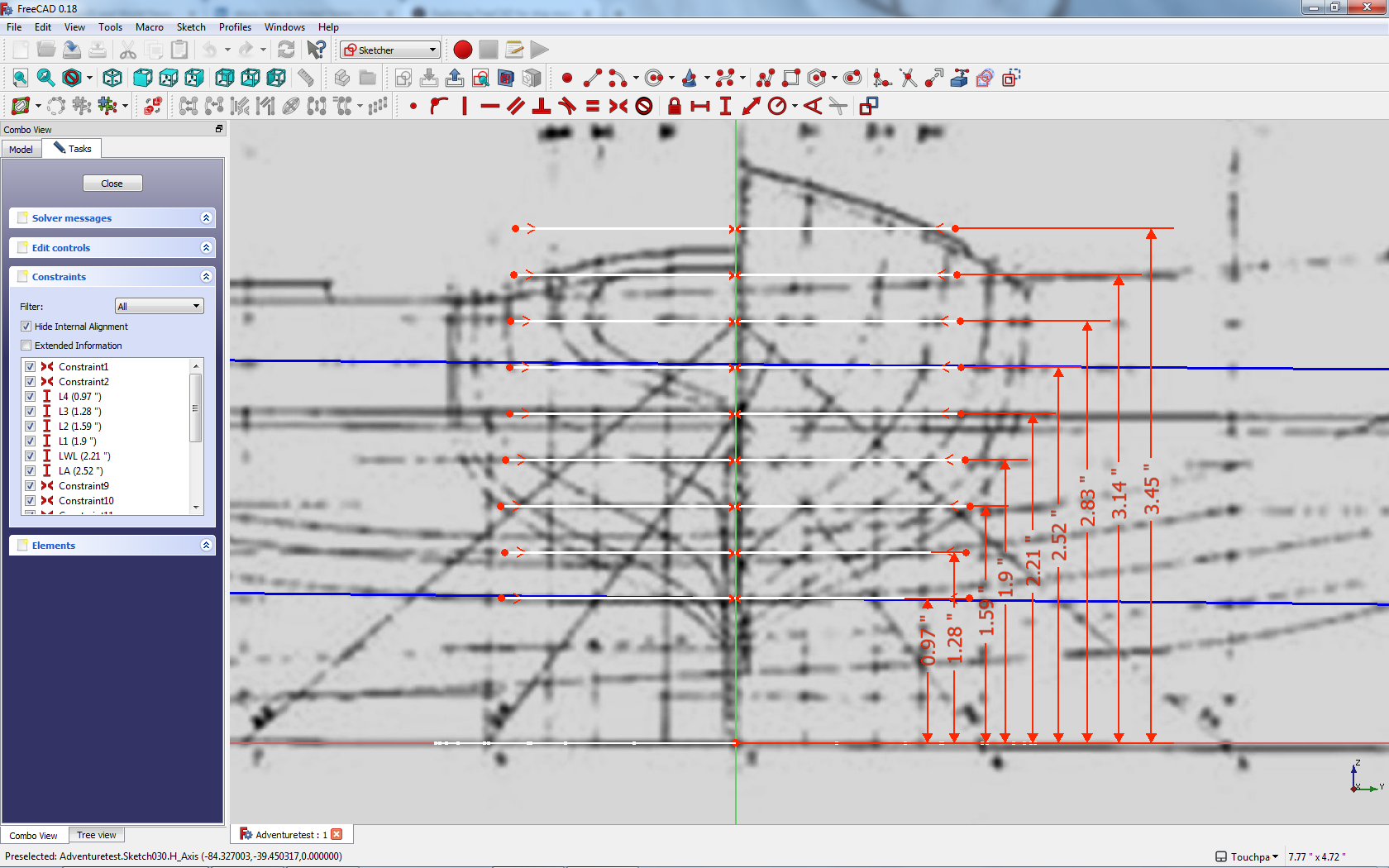
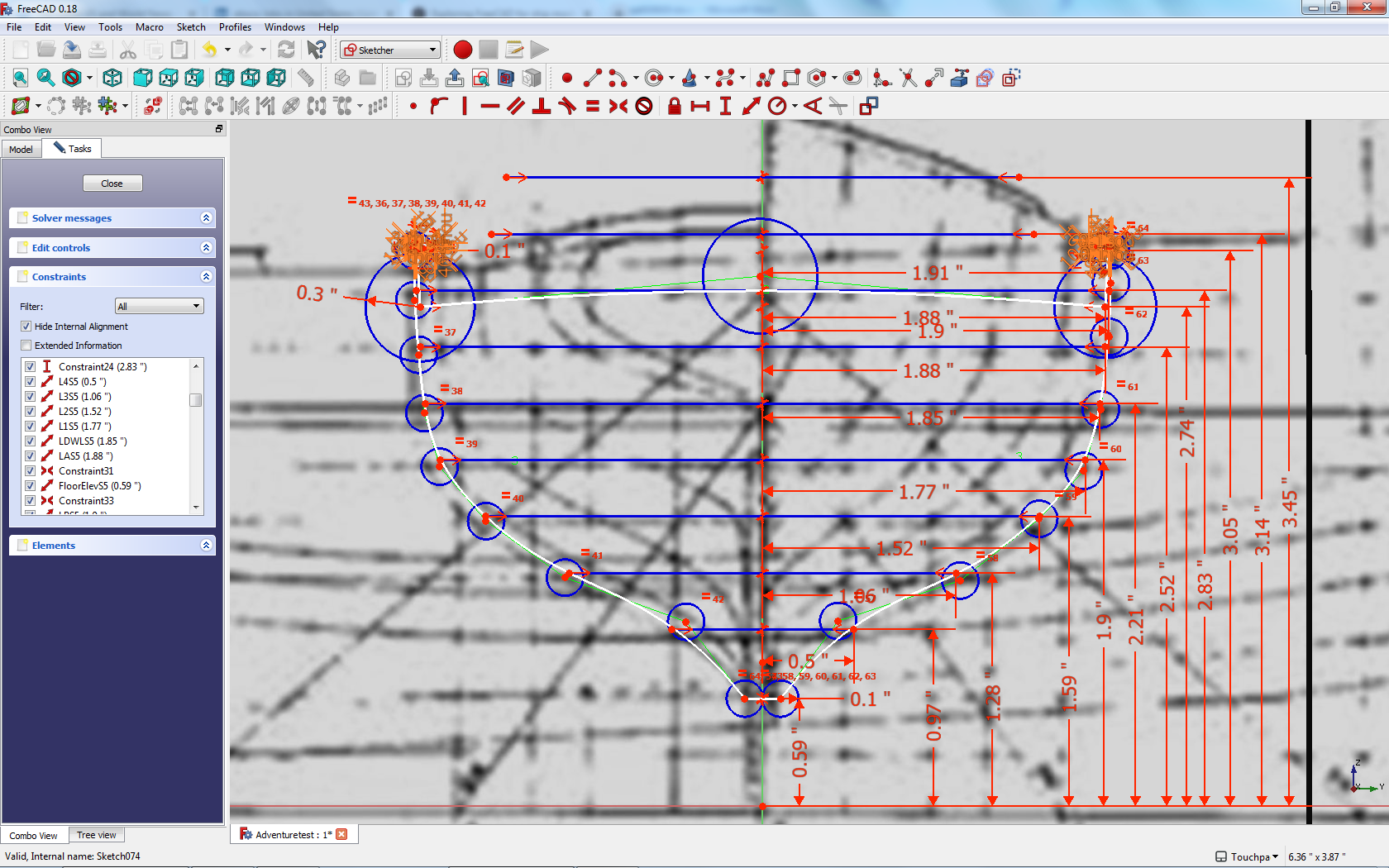
I tried to get thte ship module working and failed - no blame allocation as it could have been my understanding. Kris - I liked your start and wanted to keep up with your posts. Stage 1 - Getting to the wireframe I started by bringing in the plans using the image workbench and arranging the three views on the planes and aligning them. Then I created sketches at each station (plus a couple at the deck step I will explain later) and at each waterline with constrained construction lines at their intersection. These constrained construction lines were copied from a master frame sketch for stations and one for waterlines . Here is the view of the master station frame in the Sketcher. The lines are constrained as symetrical about the vertical (z) axis. This allows me to build the model as a full hull rather than half hull. The other constraint is the elevation above the origin. The elevation value constraints are named (alias) with the lift identity L1, L2 etc and can be reused within the model in the actual station sketches. The length of each line is not constrained in the master but is in the individual station sketches. Here is the view of Station 5 - the midway station: Each Offset value is determined by moving the end of the frame line in and out until the point lies on the line in the plan. Then the length of each line is constrained and the length constraint is named - e.g. L2S5 - my naming convention for L2 waterline intersecting Station 5. Once the offsets have been set and locked, the B-Splines are drawn to intersect the offset points. I would like to have been able to costrain the B-Spline lines rather than the control points but this is not supported. The deck cross section is drawn and the sketch is closed up. The bulwarks have a lot of constraints and look just fuzzy at this maginfication. I will discuss the bulwarks later. The waterline sketches are constructed but the construction line lengths instead of being traced are calulated for the named parameters - the L2 waterline will use L2S5 for the length of the Station 5 offset. Using the spreadsheet workbench I have also created a spread sheet with all the offsets so I can see them together. At this stage with all the station and waterline sketches along with a variant for the transom the model is emerging in a wire frame view: Note the extra station just aft of the mid station which deals with the deck step and the difference in the bulwarks. Next post will discuss the bulwarks and the lofting of the fore and aft parts.


-
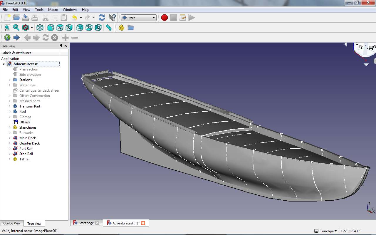
Starting this topic to explore the FreeCAD program and discuss techniques to be used. Being relatively new to the 3D CAD scene, the approaches will be relatively simple and sometimes wrong and can be improved. The project used as an example is a hull model of the New England fishing schooner Adventure and supporting information from http://schooner-adventure.org/about-us/ and details from Howard Chapelle's "The American Fishing Schooner". At some point photographs of the real schooner will resolve details. The objectives of the project are to understand some techniques for getting the 3D hull built, to get as realistic rendering as possible, and explore the opportunities for 3D printing with various options. I have been inspired by some amazing work in other topics in this forum "CAD and 3D Modelling/Drafting Plans with Software". Attached is a current rendering with many unresolved issues. I plan to go back and show how this was assembled and then move forward on the issues. Hoping that this will be of interest and that others will contribute.
-
Need CAD type program
TonyM replied to Sambini's topic in CAD and 3D Modelling/Drafting Plans with Software
Thanks Kris, Yes the Sketcher B-Spline tool is not what I wanted either but I have used the control points in the plan view to coincide with construction points from named constraint values in the cross section view which is my authoritative value. I only use the waterlines in the plan view to verify that something is not adrift in the coherence of the original plan and they are not used to construct the hull and decks which are done only from the cross section sketches. This coincides with the way a real ship is constructed - the planking will go where it wants regardless of the waterlines. However if you are using FreeCAD to develop plans this might not be accurate enough and you might have to trace the B-Splines to these control points. This is not ideal either. I think the problem is in the working of Sketcher B-Spline with constraints and it can't reconcile both types of point. The Draft B-Spline is a different animal and I have not got that working with constraints at all. It seems it might be worth starting a topic on FreeCAD. There is a lot of capability there but it has different behavior in the different workbenches. Cheers Tony -
Need CAD type program
TonyM replied to Sambini's topic in CAD and 3D Modelling/Drafting Plans with Software
Thanks, I saw your earlier post and wondered how far you had got. I could not find other posts on FreeCAD. -
Need CAD type program
TonyM replied to Sambini's topic in CAD and 3D Modelling/Drafting Plans with Software
Over the last 6 months I have been learning FreeCAD to develop a 3D rendering of a fishing schooner. The interesting feature of the software is that it is parameter driven in that you can develop offsets which can be used in a number of ways - read from a constraint in a sketch, mapped in and out of a spreadsheet embedded in he tool and used to calculate a constraint. The image scanned line drawing was imported into FreeCAD and the stations were plotted so that the intersections of waterlines and station profiles became parameter controlled locations which could be used to plot points in any view including the generation of the offset table. The waterline offsets were generated from the station offsets and splines were drawn to fit the offsets and compared to the scanned drawing so that any difference could be investigated. I had assumed that the plans were coherent in that the lines actually intersected and this validated it. I have been disappointed in the Spline tool integration into parameter constraints but maybe I don't fully understand it yet. The learn curve as with other CAD programs is quite steep but the documentation is free and all on-line and is reasonably complete given that this is open source software. There is still quite a lot of trial and error to learning. After getting the 3D wireframe developed I have used Loft and Sweep functions to generate the hull, decks, bulwarks (no stanchions yet!) and monkey rails. I have also developed a very small 3D printed model using Shapeways to prove out the file transfer process. If I get more confident that the approach is sound I may start a topic. -
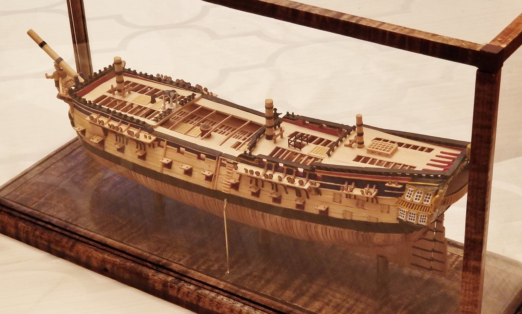
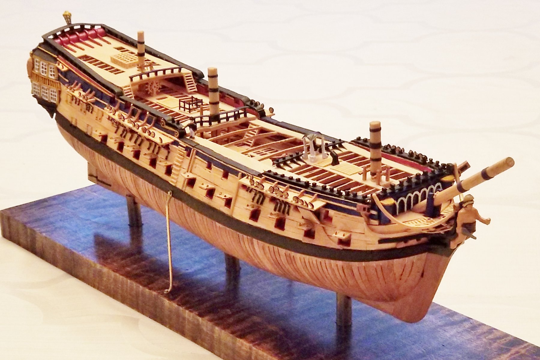
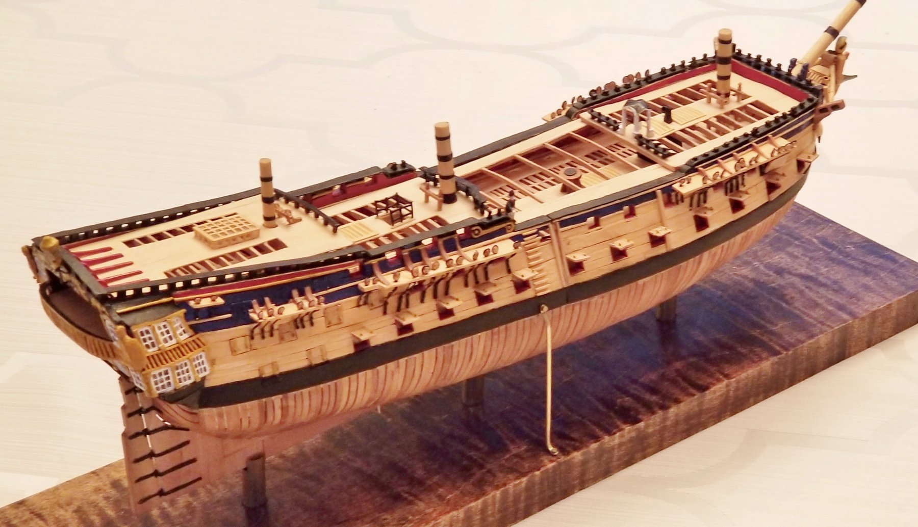
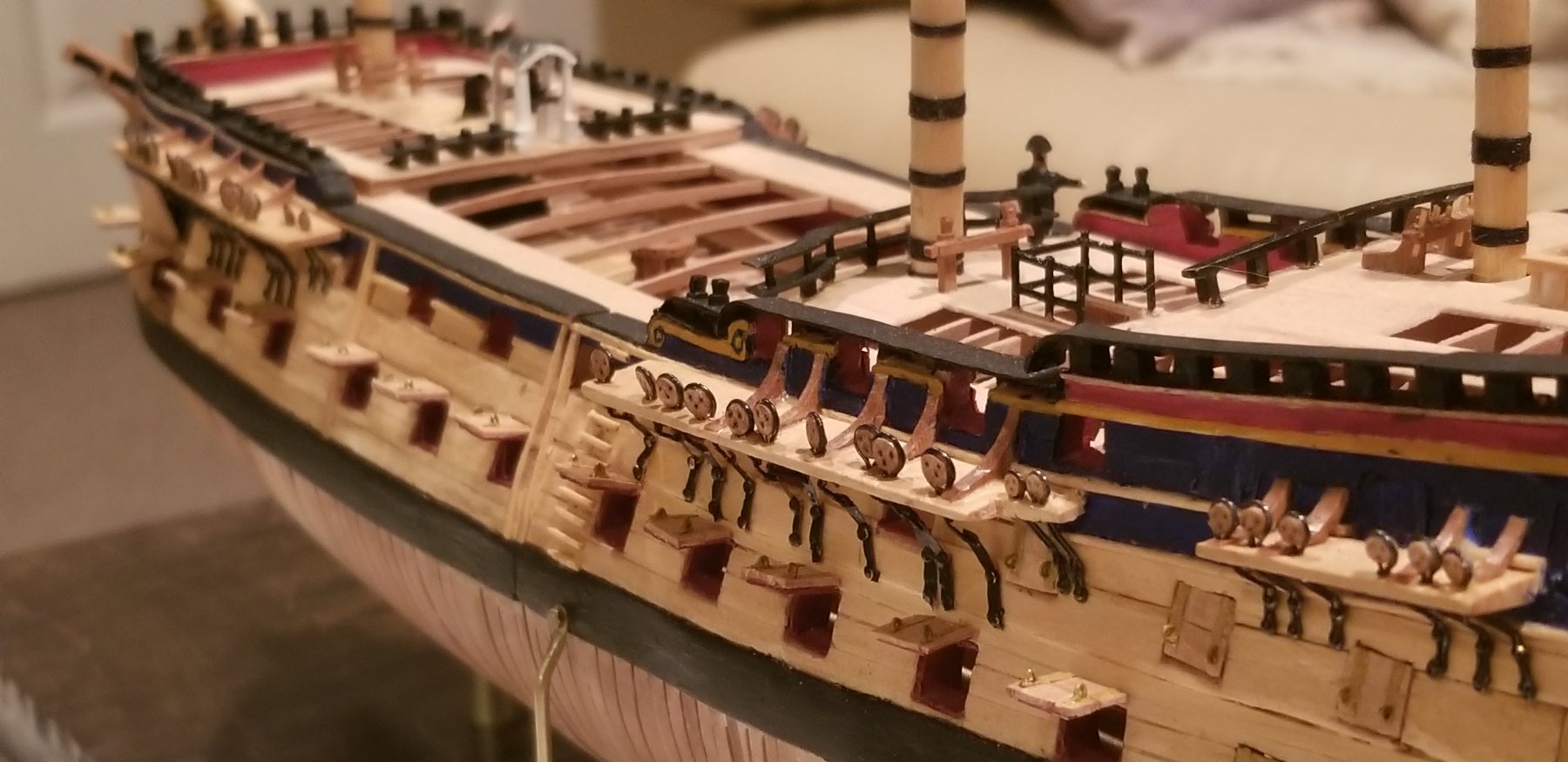
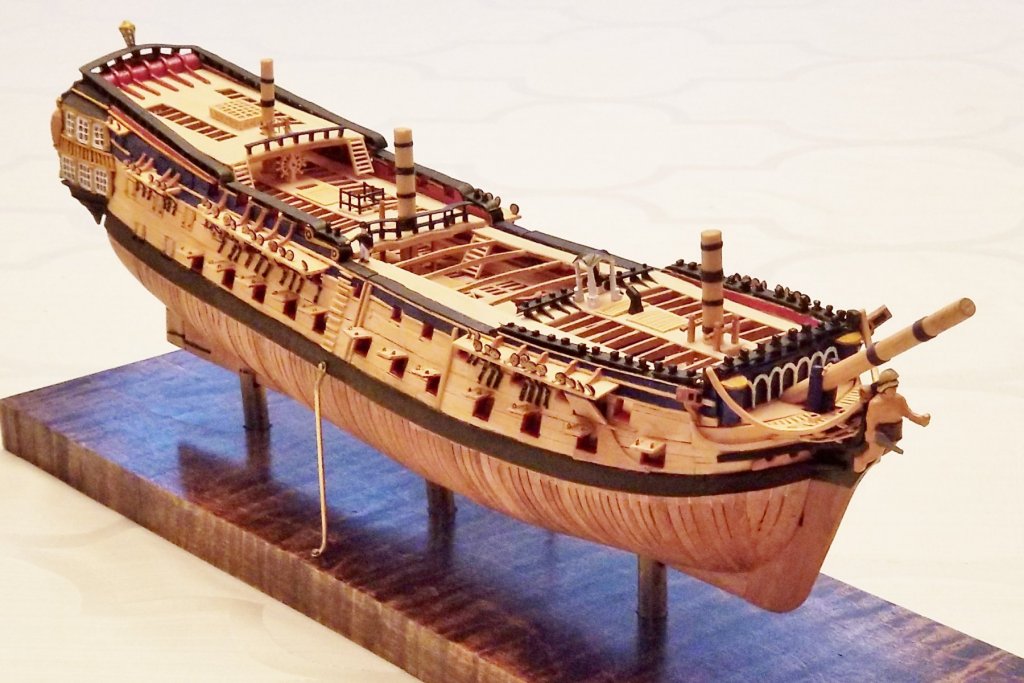
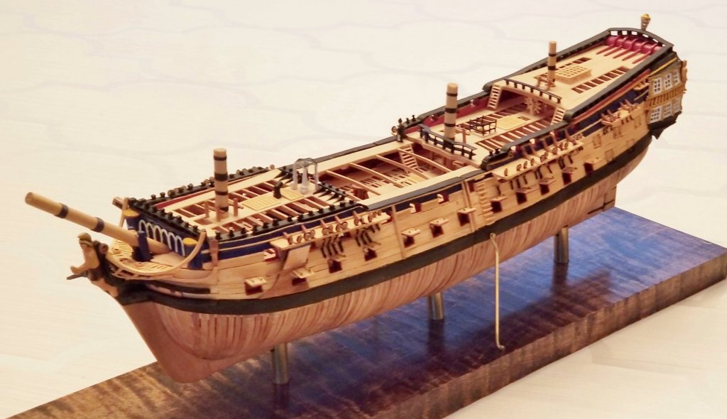
By popular demand here are some photos of the whole model in and outside the case. I found that taking the photos in lower diffused light and then increasing the brightness electronically seems to work well.


- 28 replies
-
- 6
-

-
- bellerophon
- 74 gun
- (and 1 more)
-
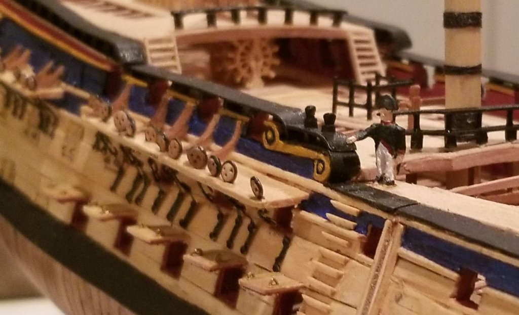
So I am wrapping up this build log. The model is finished and in a case. Napoleon is standing at the starboard gangway. Here are some final pictures.

- 28 replies
-
- 10
-
-
- bellerophon
- 74 gun
- (and 1 more)
-
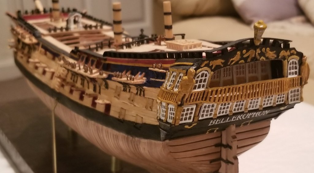
Thanks Alan, Yes I had heard of the full figure. One of the problems I have is that the scale of the head would mean a very large bow to cover the whole body, horse and wings. The Victory model kit of Vanguard showed a standing figure with sword holding the severed head of the Chimera which he had slain. I have omitted the severed head. The model is finished. I am getting the case finished and I will post pictures soon. The last stretch was doing gunport lids and deadeye chains and plates. Nothing very exciting and very repetitive.
- 28 replies
-
- 1
-
-
- bellerophon
- 74 gun
- (and 1 more)
-
Thanks Peter, I will post more when the next steps are done - Deadeyes and chains and the gunport lids. Then I will spend more time getting good pictures with better lighting. The model is going on display (even though it is still under construction) at the Merrimack Valley model ship club show starting this weekend. Tony
- 28 replies
-
- 1
-
-
- bellerophon
- 74 gun
- (and 1 more)