TonyM
-
Posts
49 -
Joined
-
Last visited


-
 daHeld73 reacted to a post in a topic:
„Święty Jerzy” („Sankt Georg”) 1627 – reconstructing an opponent of „Vasa”
daHeld73 reacted to a post in a topic:
„Święty Jerzy” („Sankt Georg”) 1627 – reconstructing an opponent of „Vasa”
-
barkingmaddbarry reacted to a post in a topic:
HMS Bellerophon by flyer - FINISHED - Amati/Victory Models - scale 1:72
-
catopower reacted to a post in a topic:
Exploring FreeCAD for ship modeling
-
catopower reacted to a post in a topic:
Exploring FreeCAD for ship modeling
-
catopower reacted to a post in a topic:
Exploring FreeCAD for ship modeling
-
mtaylor reacted to a post in a topic:
„Święty Jerzy” („Sankt Georg”) 1627 – reconstructing an opponent of „Vasa”
-
Waldemar reacted to a post in a topic:
„Święty Jerzy” („Sankt Georg”) 1627 – reconstructing an opponent of „Vasa”
-
 Waldemar, your work is very inspirational. The way your model is presented as illustrations with cutaways is very effective and perspective gives that sense of depth. The combination of nautical research and digital modeling is particularly interesting and I wonder if you have thought of a digital representation such as Sketchfab. I have done a simple CAD model "Schooner Adventure" with a build log on MSW and a viewable 3D rendering on SketchFab Schooner Adventure In the meantime I am working on the next model in Fusion 360 with CAD timber components and your work gives me a lot to think about.
 -
Bill Morrison reacted to a post in a topic:
HMS Bellerophon by flyer - FINISHED - Amati/Victory Models - scale 1:72
-
mtaylor reacted to a post in a topic:
Exploring FreeCAD for ship modeling
-
Exploring FreeCAD for ship modeling
TonyM replied to TonyM's topic in CAD and 3D Modelling/Drafting Plans with Software
Really nice work Pat. I am thinking of moving from FreeCad to Fusion 360 which would end my commitment to this topic. The export functions difficulty was the driving reason. I am exporting in STEP then converting to .GLB to load into Sketchfab. There are no texture files but the material comes across with color but not all the rendering parameters such as shininess. This required a lot of editing in Sketchfab which recognizes material by color only. The Light field device from Looking Glass Factory worked and the .GLB file was loaded into a studio software and 3D views were generated to load into the display device called Portrait. It provides a 3D presentation with parallax and stereoscopic simulation so that the model looks real inside the "case". -
Exploring FreeCAD for ship modeling
TonyM replied to TonyM's topic in CAD and 3D Modelling/Drafting Plans with Software
Some time has passed since my last post. I have rethought the rope construction which although successful was very expensive digitally when generating the rendered image which now can be loaded online at SketchFab. The model is almost complete with some more running rigging to complete and I will switch attention to the displaying of 3D models. The flat screen rendering is not very exciting and there is some new technology called "Light Field" display which I will research in the new year. It apparently gives a stereoscopic illusion using a special display screen. I will update the forum when I have more experience of this technology.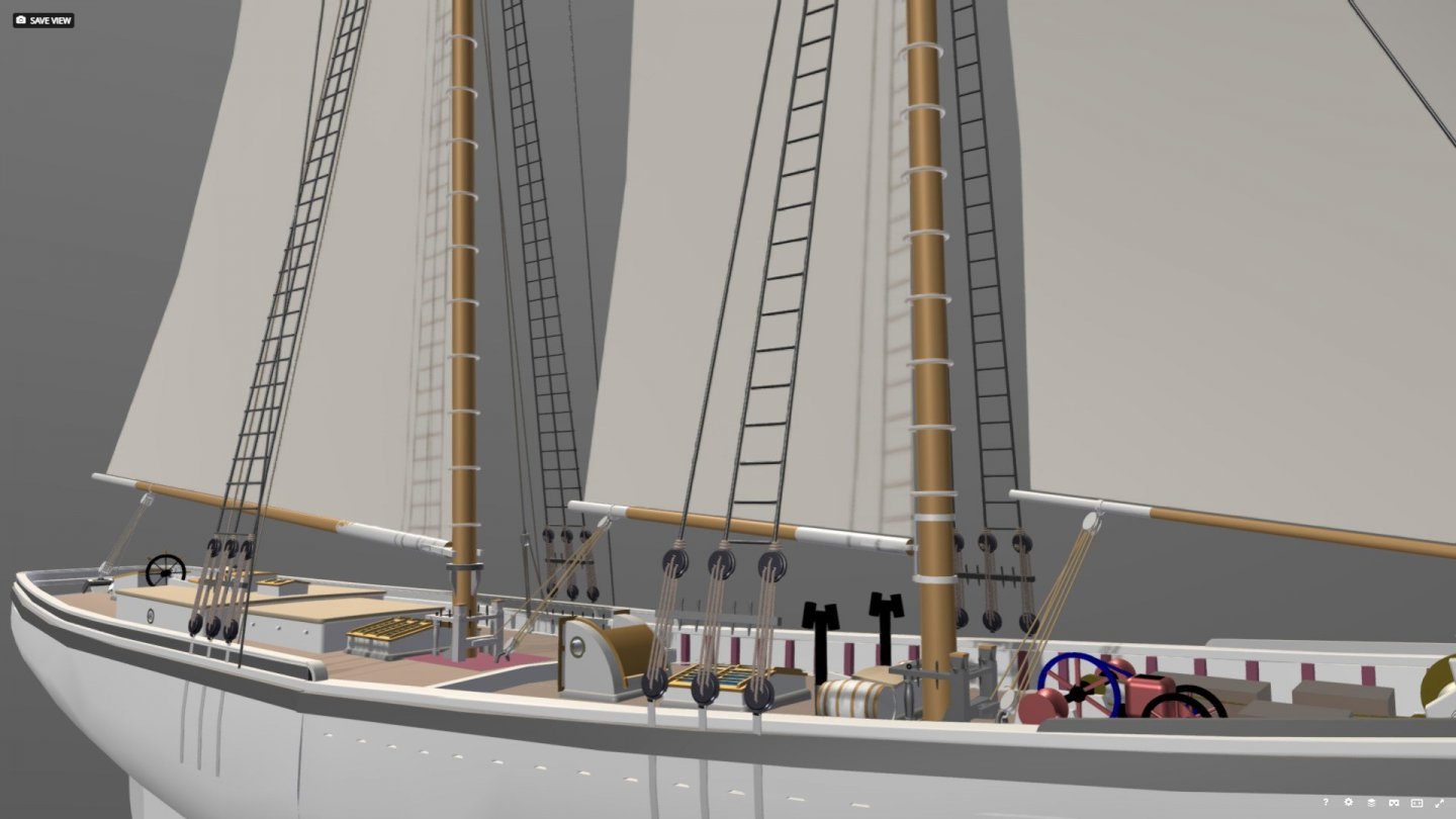
-
Exploring FreeCAD for ship modeling
TonyM replied to TonyM's topic in CAD and 3D Modelling/Drafting Plans with Software
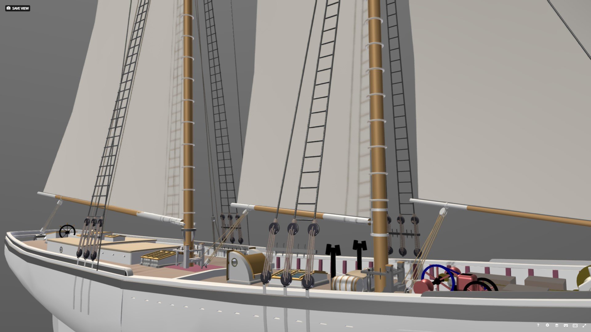
So I decided to fully rig the schooner since the display mechanism seems to be Sketchfab and my first attempts were quite encouraging. The process was a bit tedious and involved exporting the model from FreeCAD in STEP then transforming it to .glb to load into Sketchfab. When I make the image public on Sketchfab I will reference it in the posts. The rigging seemed to need sails so there is some exploration work to deal with surfaces in 3 dimensions and the projection of seams onto the curved sails. This is exposing challenges such as the geometry of the leaches (which are all straight at the moment) along with the angle of the gaffs, booms and sails to the centerline (which are also straight at the moment). Obviously this is just a rough setup which will give me an idea of what is possible but progress in happening.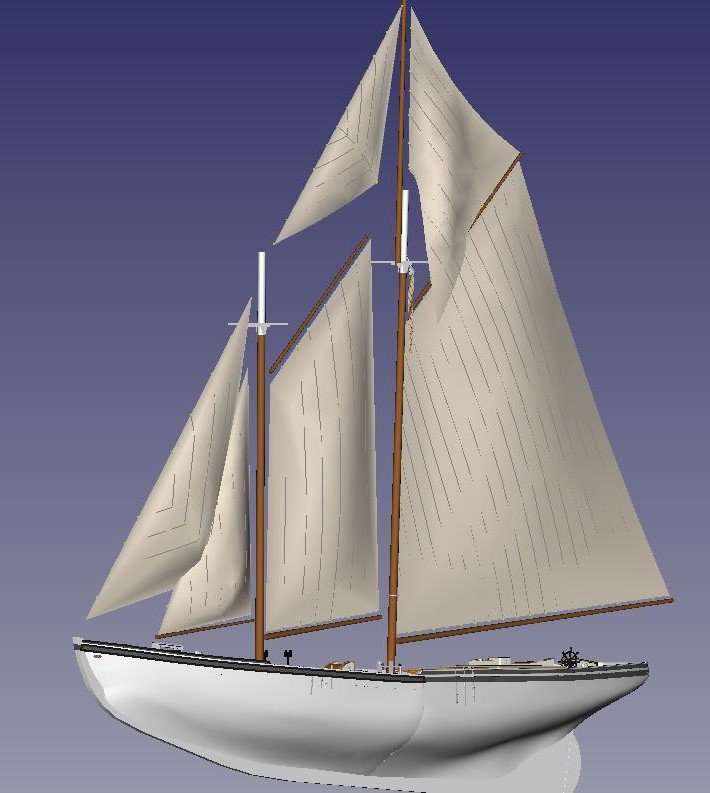
-
TonyM reacted to a post in a topic:
Exploring FreeCAD for ship modeling
-
Exploring FreeCAD for ship modeling
TonyM replied to TonyM's topic in CAD and 3D Modelling/Drafting Plans with Software
Thanks Terry, Actually it s not as bad as it looks. I have segments of straight rope that I fuse together and half circles which were cut from the ring earlier in this post. It is still a bit rough and there is some discoloration which I will fix but the idea is to have rope components that I can assemble. Tony -
Exploring FreeCAD for ship modeling
TonyM replied to TonyM's topic in CAD and 3D Modelling/Drafting Plans with Software
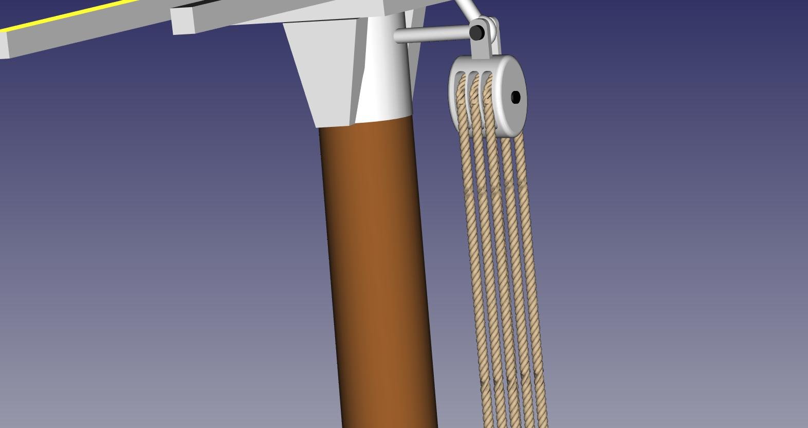
Sorry about the delay in responding to Sailor and Dane. Sailor - Yes the tuck was around 8 oclock and was not pretty. I can probably work to improve it but the ring was just to explore the method which was difficult. Dane - yes it is done from 3 strands. I have an easy method for a straight rope which is to form a polar array of 3 helixes and then sweep a circle of each strand cross section along each helix. The curved rope (shown as a ring) is done by creating a polar array of triangles and 3D splines are woven through the points of each triangle forming 3D helixes around the array of triangles. Then I sweep the strand cross section along the splines. Very time consuming and I want to find a better way. The purpose of the circular rope is to feed it through a block. Here is a fragment of the schooner with the main upper throat block.
-
Tony,
I just downloaded a copy of FreeCAD two days ago. I bought a CNC Router about a year and a half ago with a cut area of 17” x 17”. I was hoping to use the router when I retire.... Well currently only made a sign for my dentist, a sign for our subdivision with Twin Oaks (30,000 lines of code) and a rough draft of engraved shrimp boat. The sign for the Subdivision was a bit small and had to make it in three parts. I was thinking of making a toy sailing skiff with a mast and sail. I tried to use the Ship workbench provided by FreeCAD. I have not been able to merge Ship with other views. My laptop may be too old. I was going to use just a plain flat view of the top view which would become the deck of the skiff. I would then add seats and a place to hold the mast. The hull top shape would be the same as the deck. I was thinking, the deck would fit into the hull. The skiff would only be 8 or 10 inches long. Can I get a FreeCAD file of the top shape (flat view only) of a plain flat deck or tell me someone who could help me?-
Hi Sam,
I did not have much luck with the Ship workbench.
Based on what you are describing I would create a horizontal rectangle to be larger than the hull and then extrude the rectangle to form the solid deck. Then make a boolean intersection operation with the hull so that the deck edge is aligned with the hull external shape.
-
-
Exploring FreeCAD for ship modeling
TonyM replied to TonyM's topic in CAD and 3D Modelling/Drafting Plans with Software
Here is a rope grommet built up from 3 strands.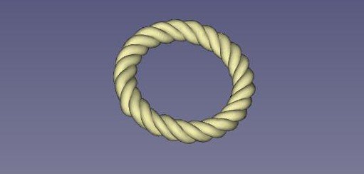
-
Exploring FreeCAD for ship modeling
TonyM replied to TonyM's topic in CAD and 3D Modelling/Drafting Plans with Software
Here is a view of the latest state of the model. Some challenging items are to get the deck seams looking right. Although this is not the finest resolution image, belaying pins are just visible on the main Fife Rail.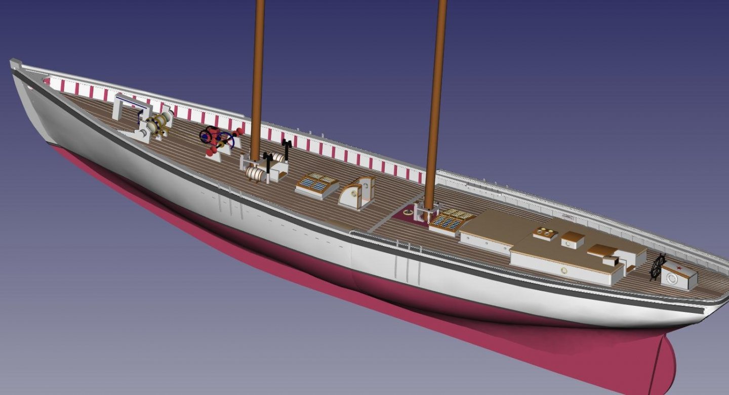
-
Exploring FreeCAD for ship modeling
TonyM replied to TonyM's topic in CAD and 3D Modelling/Drafting Plans with Software
Thanks SteveWTI, I have not had a problem with speed. The model is now about 30 Mb in its FreeCAD format and if it does a complete recalc takes about 10 secs. In most cases a complete recalc is not needed and it is fast. No I did not do any Python work it was all straight GUI. The size of the model has increased dramatically because I am playing around with rope in 3D and it is very data intensive. I will post a new image of the model with a whole lot of deck furniture done. -
Blender startup for ship design
TonyM replied to edbardet's topic in CAD and 3D Modelling/Drafting Plans with Software
Ed, I am using FreeCAD to build the 3D model and have just started importing it into Blender using .wrl. See my other posts on FreeCAD. Most of the model seems to be there but I am struggling with the representation of parts and surfaces in Blender. It recogizes parts but seems to need splitting of surfaces if the surfaces have a different material. If anybody has experience it would be greatly appreciated. Tony -
Exploring FreeCAD for ship modeling
TonyM replied to TonyM's topic in CAD and 3D Modelling/Drafting Plans with Software
Thought I would post the latest developments on my Schooner. The next addition has been the stanchions which are built using a solid loft along templates housed in the bulwark part of each station. This solid representes the KnightHeads and Hawsepieces at the bow and then is cut using a cutting solid into the distinct stanchions. I do one set for the main deck and one for the quarter deck. I have colored then red to distinguish. At the bow I cut the Hawse pipe through the Hawse pieces and the hull. The next to be added was the monkey rail which wraps round the transom as the taffrail. This is the first attempt and is quite difficult. I will probably rework this soon. The seat as an extension of the main cap is not shaped correctly yet.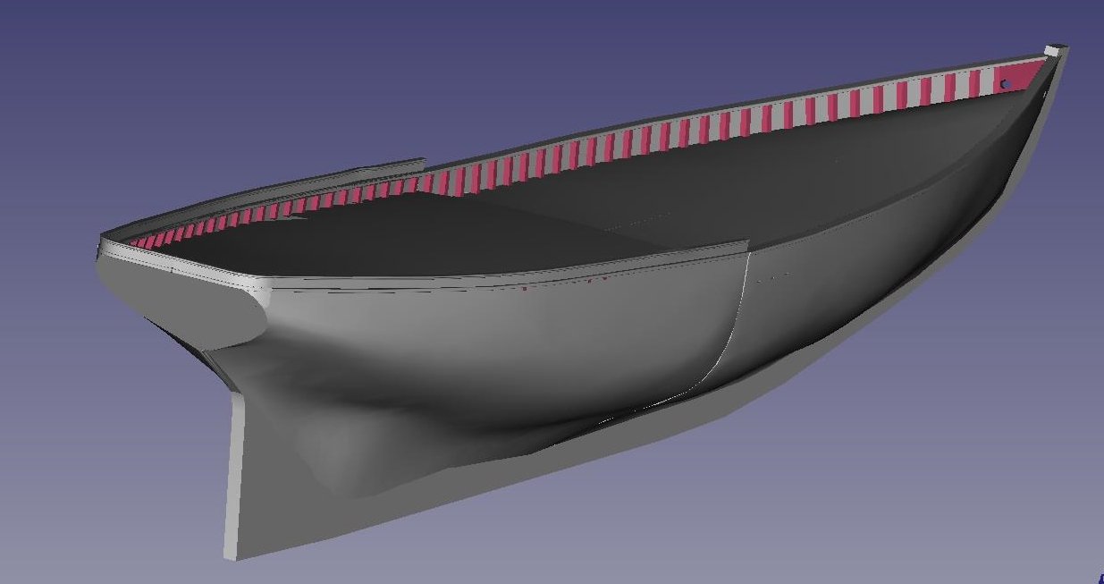
-
Exploring FreeCAD for ship modeling
TonyM replied to TonyM's topic in CAD and 3D Modelling/Drafting Plans with Software
Kris, Some of this work was done before I joined the forum and has just needed to be refactored for the changes. So it is not as fast as it appears. -
TonyM reacted to a post in a topic:
Exploring FreeCAD for ship modeling
-
Exploring FreeCAD for ship modeling
TonyM replied to TonyM's topic in CAD and 3D Modelling/Drafting Plans with Software
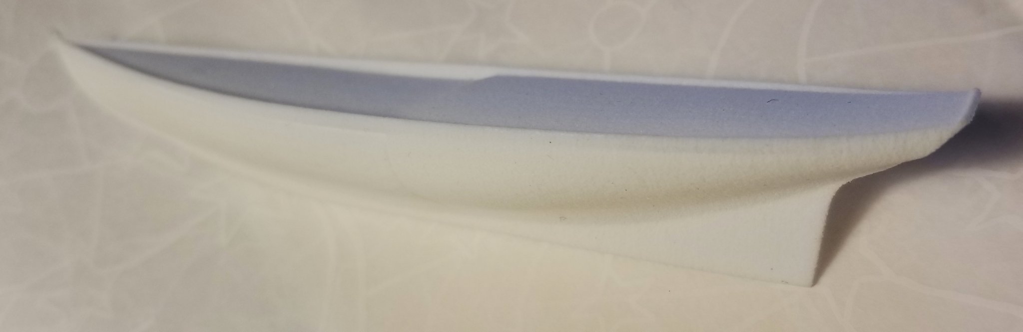
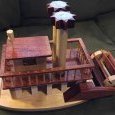
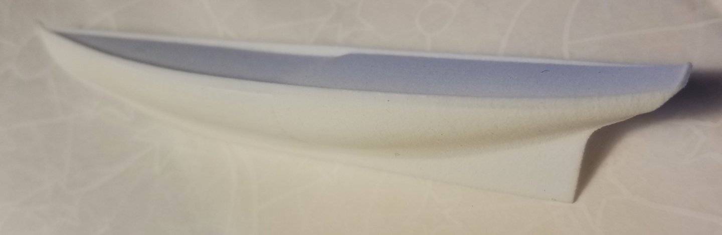
It is probably time to discuss intention. I had started with some ideas in mind like building the real model in wood but the more I explored the topic which is quite well covered in this forum, the more I realized there are other possibilities such as creating a realistic image or generating a 3D printed model. I had not shown the surface generation which was done to create the waterlines by lofting the stations. The lofting was done in two parts - the forward main deck and the quarterdeck due to the disruption of the step. Both parts are then mirrored to get the port half. In hindsight it might be better to separate the generation of the decks but doing it this way is easier since the deck positioning is defined in the frame sketches. There is some disagreement between the rabet at the stern and the decision of the FreeCAD lofting operation but it is expected. This can be corrected if necessary with an additional station just forward of the rudder and extend the next station down to the rabet. As this has been exploration, I tested out 3D printing with Shapeways on a smaller version by scaling down at time of printing. The file exchange went quite well and the model appeared in their Shapeways online viewer tool. I then ordered a print in the cheapest possible material just to see what would happen. This was an earlier version of the model. Not a very good photograph but there is not much detail to show. All the flaws in the model are faithfully reproduced. Some of my original iseas were to create plugs to build ships boats. It seems that you can build jigs and plugs quite easily and are not part of the finished model. I also thought about building the frames by 3D printing and then finish by planking in wood - a hybrid approach. In the meantime there is a lot more detail to create.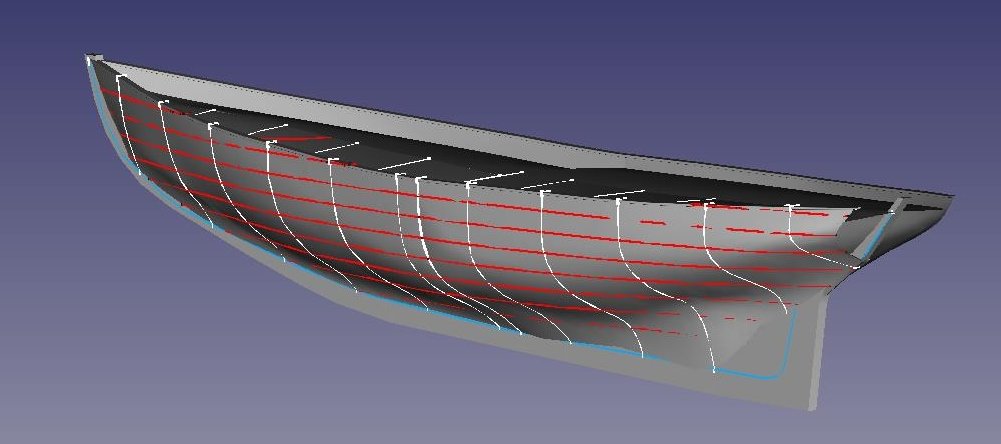
-
Exploring FreeCAD for ship modeling
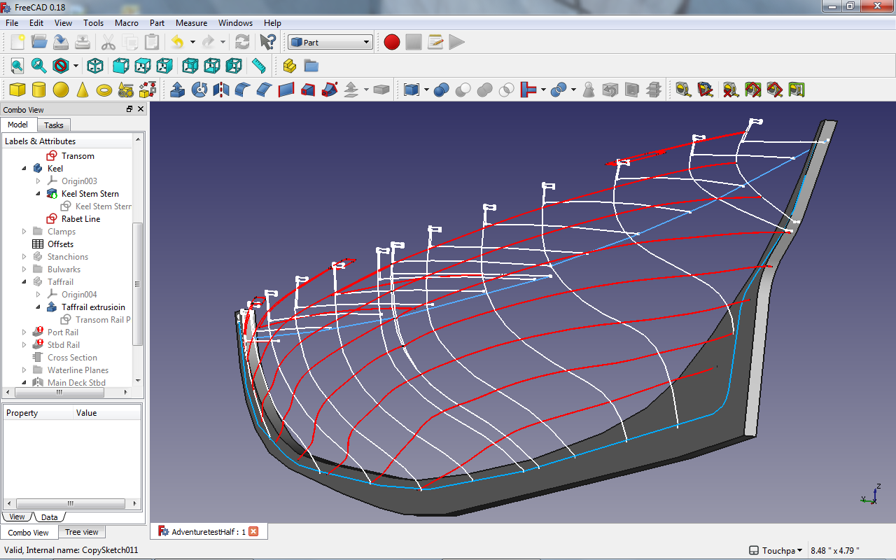
TonyM replied to TonyM's topic in CAD and 3D Modelling/Drafting Plans with Software
Trying to catch up on these good ideas. Firstly, I have reduced the model to a half hull (port) and tested the mirroring of it to a whole hull. As I thought, there are problems with the decks which are lofted along with the stations and do not intersect correctly at the center line. The crown of the decking is controlled through the station splines and perpendicular constraints are not allowed on splines. However the symetry is much better. I took Phil's approach to generating the waterlines (shown in red below) by creating a plane for each level and intersecting them with the hull surface which is lofted from the stations. This means that I don't have to worry about getting the offsets for the waterlines to be the same as the stations - it will generate them automatically. As a result of this I can go back to manual editing the stations against the original plans. The offsets are read from the stations and pulled into a spreadsheet for ease of examination. As expected, there are some irregularities showing in the waterlines and I will examine them and correct the stations. I did pay some attentin to the rabets which are drawn in blue and are projected off the centerline to still show when the keel is extruded. The rabets determine the lower ends of the stations which are represented by the bottom of the frame floors. I also developed a guidance line for the crown of the deck at the midsection to start to get the deck camber correct - still in progress.