HOLIDAY DONATION DRIVE - SUPPORT MSW - DO YOUR PART TO KEEP THIS GREAT FORUM GOING! (Only 13 donations so far - C'mon guys!)
×


TonyM
-
Posts
49 -
Joined
-
Last visited
Content Type
Profiles
Forums
Gallery
Events
Everything posted by TonyM
-
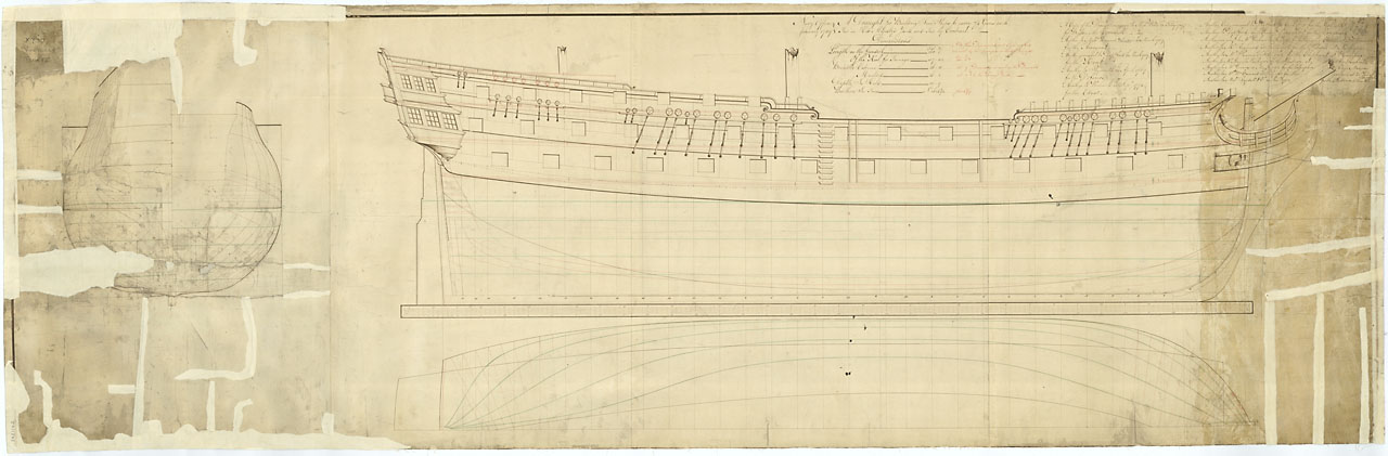
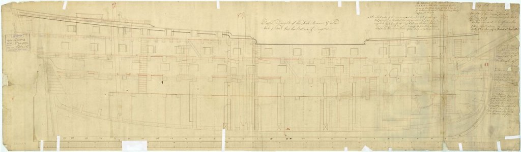
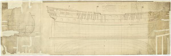
 Alan's comments are interesting - I went through the same questions but I seem to be working from a different plan. These plans are a long time before Bellerophon was put into service and even longer before Trafalgar by which time she had the Nelson paint arrangement aligned to the gunports as opposed to the previous alignment to the wales. The wording from NMM associated with this is: Description Scale: 1:48. Plan showing the body plan, sheer lines, and longitudinal half-breadth for building Cornwall (1761), Arrogant (1761), and Kent (1762), and later for Defence (1763), Edgar (1779), Goliath (1781), Vanguard (1787), Excellent (1787), Saturn (1786), Elephant (1786), Illustrious (1789), Bellerophon (1786), Zealous (1785), and Audacious (1785), all 74-gun Third Rate, two-deckers. Date made January 1759 Place made Navy Office Credit National Maritime Museum, Greenwich, London Materials black ink; green ink; red ink; paper Measurements Sheet: 574 mm x 1835 mm Depending on the period you want to represent the poop railings were added later - I think that it would have been easy to fall overboard unless there were hammock rails fitted. The second plan seemed to show the railing continuing over the gunports. I also worked from the plans of the Victory model to see if there was further clarification. Peter - good luck with your project. Tony e
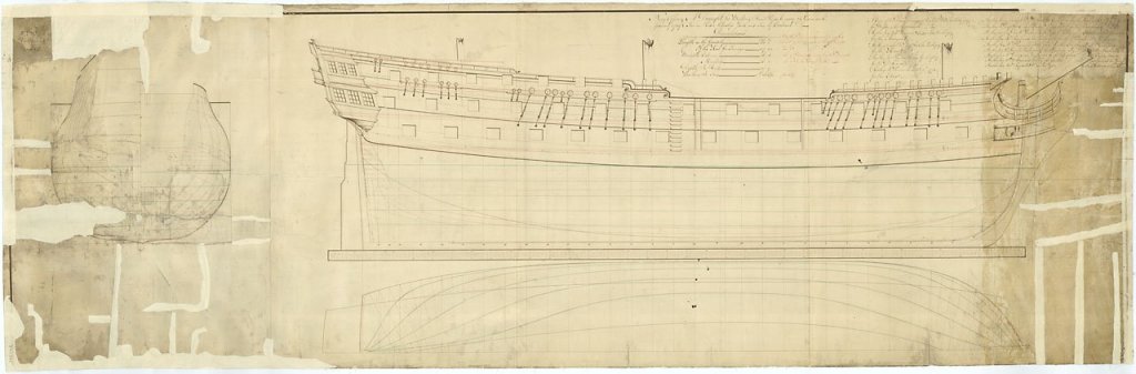
- 366 replies
-
- 6
-

-
- bellerophon
- victory models
- (and 2 more)
-
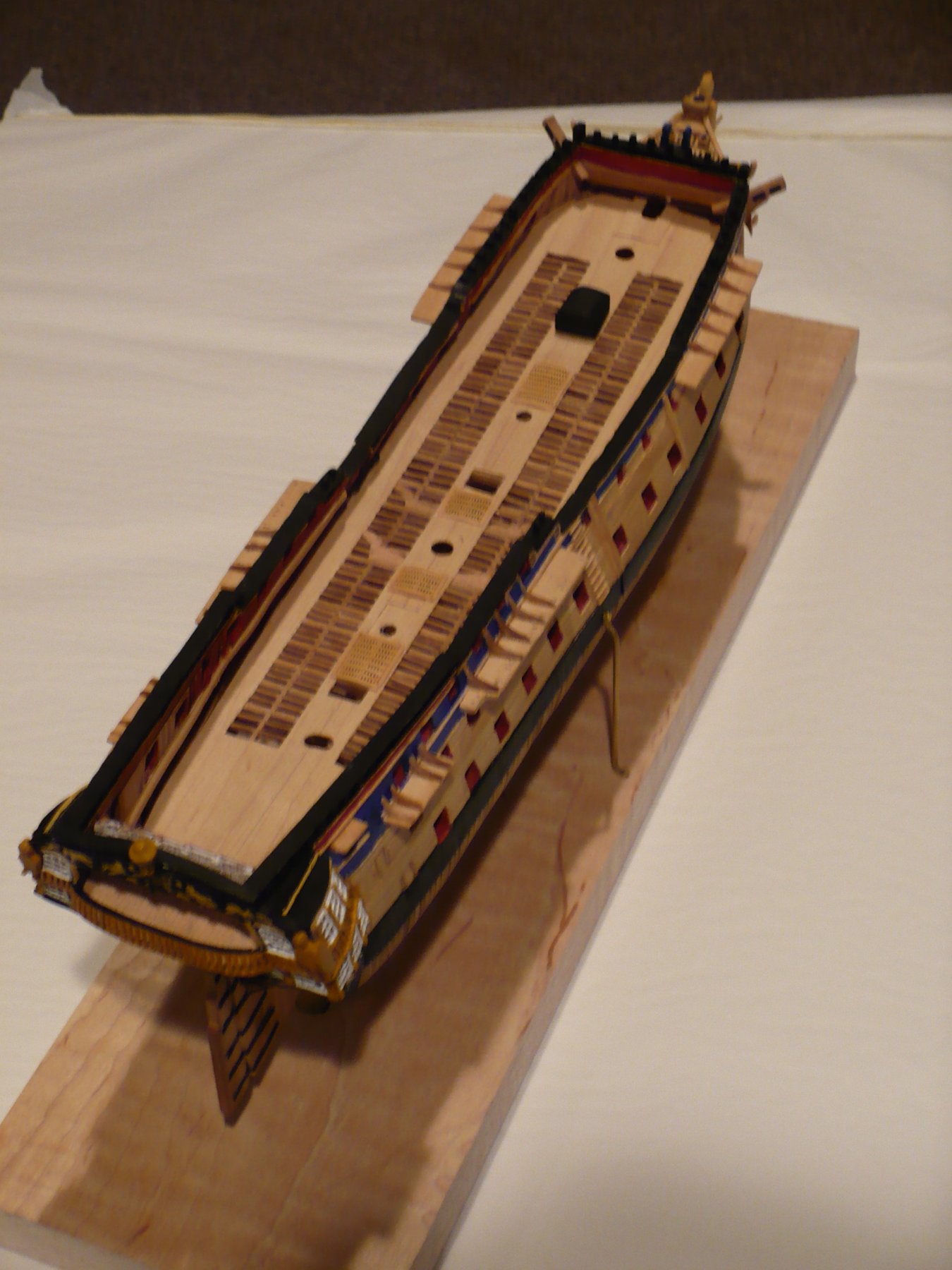
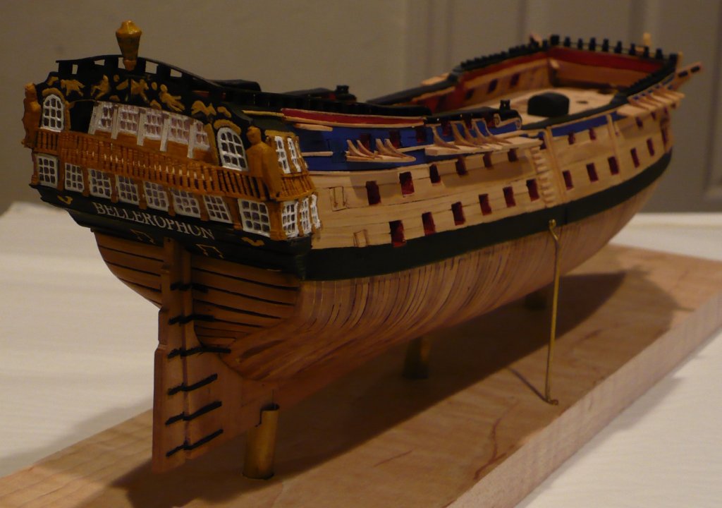
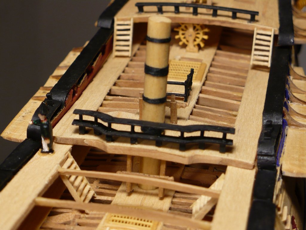
So - a long time has passed since I last posted. There has been a lot of development some of which I was not ready to share. I found some slow growth pine branches which came down in our yard and I dried them off and cut boards radially from the center so when I cut the planks along the grain there was hardly any visible. The picture above shows the side planking with the quarter galleries and rudder finished. The gun deck and upper deck are installed. The method is that the decks are removable and rest on the clamps. The gun deck has only bitts and hatches installed and the deck planking is complete. The deck planking is maple deeply scribed. In a view from above the upper deck is partially planked to get a view through to the gun deck. Beams, carlings and ledges are visible in the cutaways. Gratings and ladders are installed and openings for masts and capstans are visible. Forward is the stove which will be mostly obscured by the focsle. The focsle, quarter deck an poop are dropped in and the masts inserted to pin the whole assembly together. Because HMS Bellerophon was the ship where Napoleon surrendered to England in 1815 I have added a very small figure where he was reported as standing when the ship was anchored in Plymouth Sound and the crowds would come out to see him. At 1:144 scale he is only 1/2 inch high. The whole model is about 14 inches long. There is still finishing work to be done and the deadeys and gun port lids to be constructed.


- 28 replies
-
- 11
-
-
- bellerophon
- 74 gun
- (and 1 more)
-
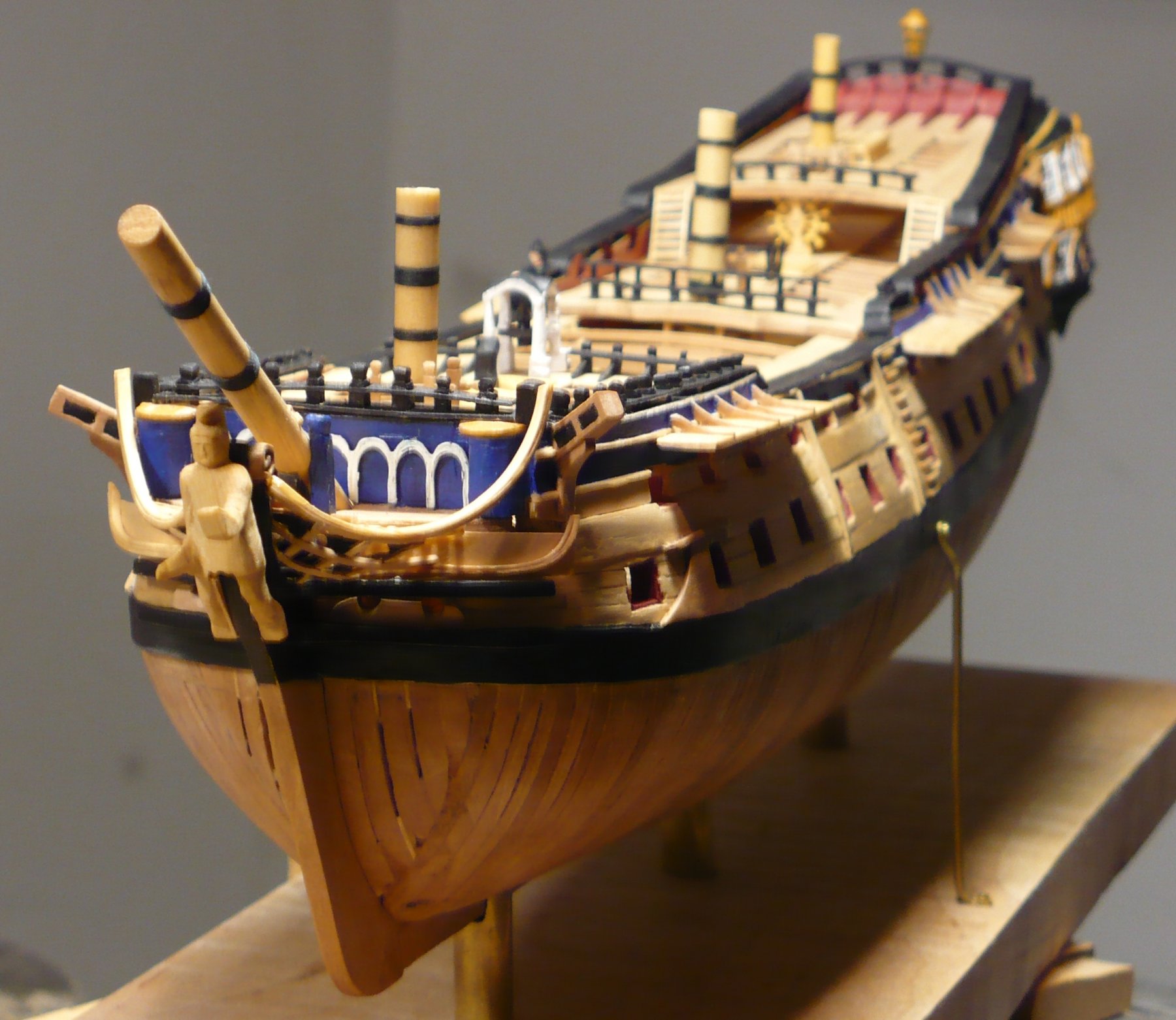
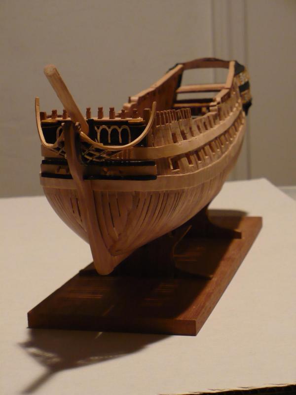
Thanks Tim, as we did not have a show n tell I did not bring it. Moving along - the wales are in place with a reasonable fit to the lines and gunports. I have used my other camera which is much better so here is a general view from the port bow.
- 28 replies
-
- 11
-
-
- bellerophon
- 74 gun
- (and 1 more)
-
My photos are not coming out well. Here is a photo taken by a colleague at the Merrimack Valley Model Ship Club where I showed progress.

- 28 replies
-
- 17
-
-
- bellerophon
- 74 gun
- (and 1 more)
-
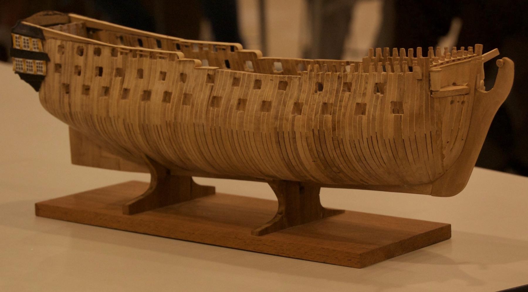
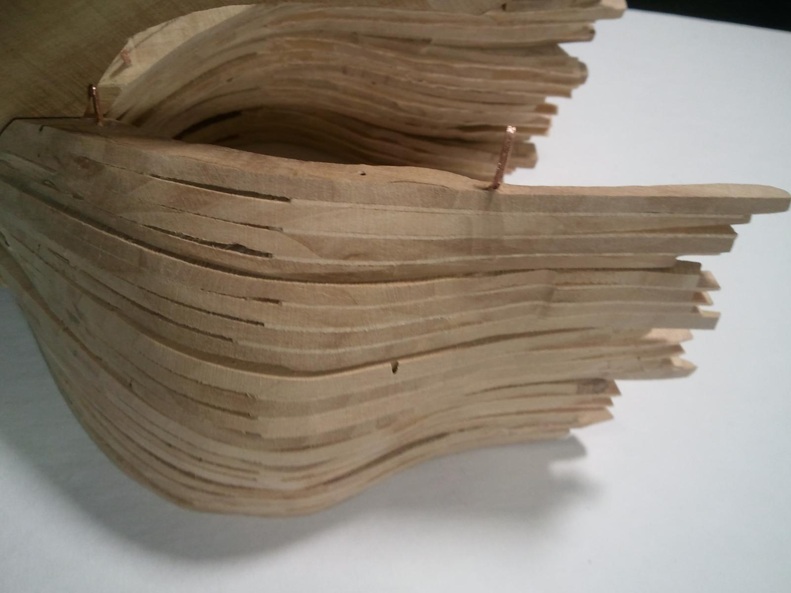
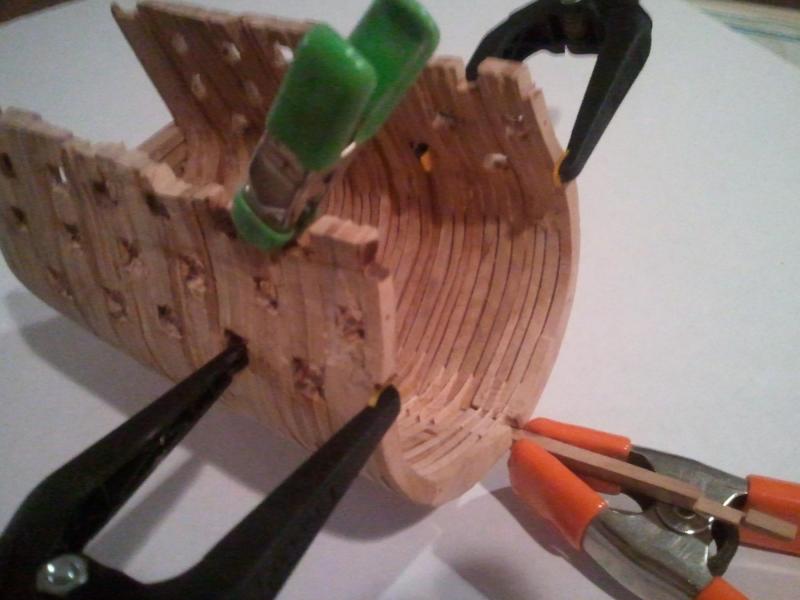
So a long time has passed and many frames >100 have been assembled. The templates were changed to ensure that the upper holes are aligned in a horizontal line the same height above the keel for all sections. In these holes copper pins are inserted to align one section with the next. The photo shows a section being glued to its adjacent section with the keel push fit to ensure that the two pins and the keel are all aligned. Note that the rough gunport openings have been cut before gluing the sections. This allows a nice clamp location to keep pressure on the sections. All the sections are assembled this way but at the midpoint the sections are push fit on the pins and not glued. Keel forward with stem and keel aft with stern are push fit into the sections and are joined together in the middle with a wedged scarph. Rough fairing has been done inside and more fairing externally to start to see the lines emerge. Only enough is taken off so that the adjacent frames of two joined sections form a double frame. In the meantime some work has taken place on the stern galleries as I expect them to be tricky and to get the geometry working. More about these in the next post

- 28 replies
-
- 13
-
-
- bellerophon
- 74 gun
- (and 1 more)
-
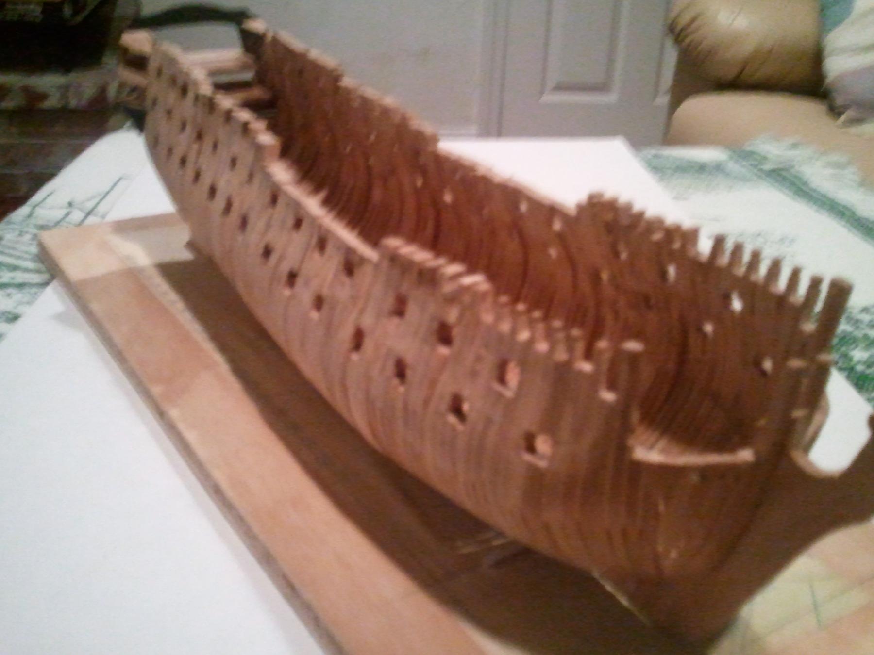
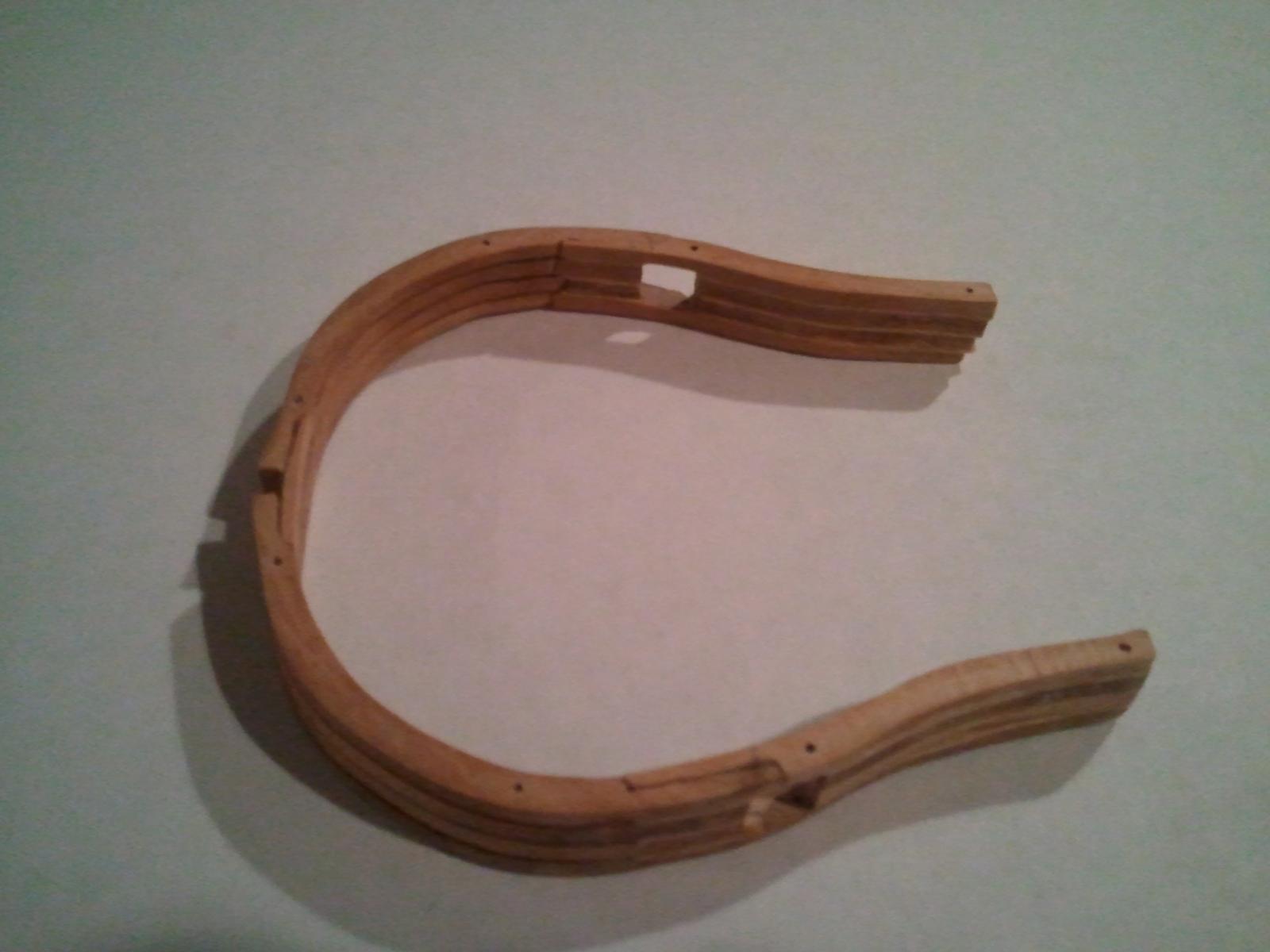
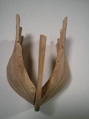
So things are starting to move forward again. Started work on the bow cant frames as I think they will be quite difficult. There are 19 pairs of can frames in the bow, The original plan to make frames out of 4 futtocks has been reduced to 2. Each regular frame will be made in 2 pieces joined together with a chock at the keel. The cant frames will therefore be one piece. Sections consisting of 4 cant half frames are assembled on the jig with spacers only between the outboard parts of the frame. The frames at the keel are glued to each other without spacers. The spacer width was calculated to create the right cant angle and is adjusted by shaving the frames at the keel to increase the angle. Locator pin holes are drilled at the top and bottom of each cant frame and copper pins are glued facing forward. This allows each section to locate with its adjacent section prior to gluing the sections together. This is key to the ability to fair the sections outside and inside. The intention is to delay this gluing for as long as possible. The sections will be faired using a 1 x 30" belt sander. Each cant section can be compared against its opposite because sections are not glued together. The important think is to get the cant geometry right. With an initial fairing with 120 grit on the belt sander the lines are starting to appear particularly the transition from the bow into the tumblehome.

- 28 replies
-
- 13
-
-
- bellerophon
- 74 gun
- (and 1 more)
-
Yes I started the log but it was some time after I started working on the model. The main obstacle and delay is not to do with the plans but with the wood I intend to use. I got hold of some logs of Dogwood a few years ago and built my last model from it. After the logs had dried out I halved them (lengthwise) and was then able to resaw boards from the half log using my bandsaw. My bandsaw from Micro-Mark is a 9 inch RBS230. The max wood thickness it will cut is about 3.5 inches and to do that requires a skip tooth blade. I could not find a 59.5 inch skip tooth blade and made one by breaking off alternate teeth and grinding the remains as well as sharpening the teeth. To start with it worked extremely well. So I started preparing this wood for HMS Bellerophon. I was able to find new skip tooth 59.5 inch blades but the cutting rate was much slower than the earlier use. The problem seemed to be sharpening but however much I sharpened it would not go faster and seemed to be losing power. I am not an expert on power tools. A fellow modeler recommended I look to see if sawdust had got into the motor so I took off the motor - it was sealed and turning quite easily. In the process of replacing the motor to the frame, I noticed that there were slots for the bolts to allow for tightening the belt between the motor and the pulley on the lower blade wheel. With the belt tightened appropriately, the bandsaw now cuts like the first time. However, this has distracted me for months and I can now get back to the action. Boards from which the frame futtocks will be cut are now easily resawed to about 100 thou which at my scale is 14.4 inches. They will be finished in a thickness sander. There is now no further excuse for delay.
- 28 replies
-
- 5
-
-
- bellerophon
- 74 gun
- (and 1 more)
-
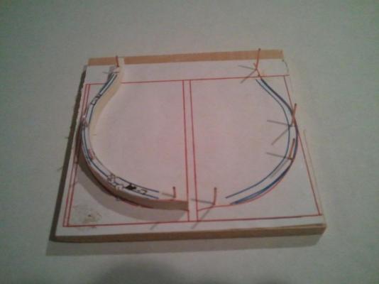
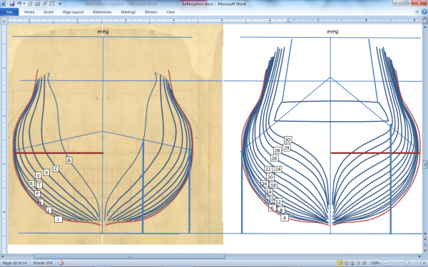
The technique I used for plans is simple. I downloaded the jpg of 74 gun 3rd rate from NMM and copied it into MS Word. The length of the gun deck was set using the Word Picture Tools line at the required measurement. Based on the ship's gun deck length (168 ft) and the scale 1:144 the line was sized to the correct length. The line was superimposed over the image and the image sized so that the gun deck matched the line. This image sizing must be preserved for all parts of the plan including the sections. The section part of the plan was cropped to the half for both the forward and after sections and replicated, flipped horizontally and joined with the other half so there were two diagrams of full sections one forward and one aft. With MS Word picture tools, the lines on the sections were drawn over with the spline tool so they would be clearly visible. Since the sections are by station, each set of frames between stations will be identical (to start with) later on they will be faired to get the correct frame thickness. Each section frame lines are copied separately and printed twice - once for pasting onto a template which will be used for shaping the frames and another mounted on a wood block as the jig for assembling the section frames. Here is shown a jig with a template mounted on the pins which hold the frames. The pins are the same distance apart for the upper and lower futtocks so that they will fit in the shaping jig as will come in the next post. A test set of frames was built on the jig with 4 frames each of 4 futtocks and the spacers of veneer. The scarphs were made to strengthen the futtock joints and chocks joined the first futtocks. The scarphs have been changed to straight diagonal to ease the shaping.

- 28 replies
-
- 16
-
-
- bellerophon
- 74 gun
- (and 1 more)
-
So I am starting my build log and I don't know whether it will help or hinder the building of this model. Maybe others have some experience of the effect. Started selection of the next model last year and ran into the history of Napoleon surrendering on board HMS Bellerophon 200 years ago. I have wanted to do an admiralty board model for some time and was inspired by Phillip Reed's book "Building a Miniature Navy Board Model" but I don't want to go to 1:196 yet! So this will be a semi miniature scale. This is my first Build Log so I am getting oriented with the process. TonyM
- 28 replies
-
- 10
-
-
- bellerophon
- 74 gun
- (and 1 more)