
John Fox III
-
Posts
119 -
Joined
-
Last visited
Content Type
Profiles
Forums
Gallery
Events
Everything posted by John Fox III
-

Experiments in Card/Paper Modeling
John Fox III replied to John Fox III's topic in Card and Paper Models
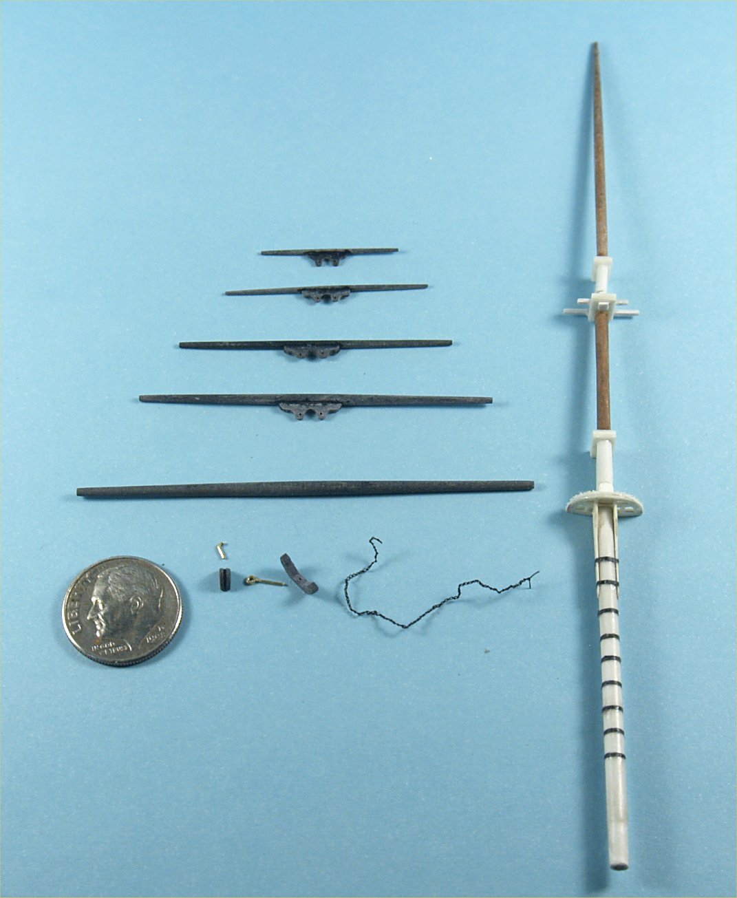
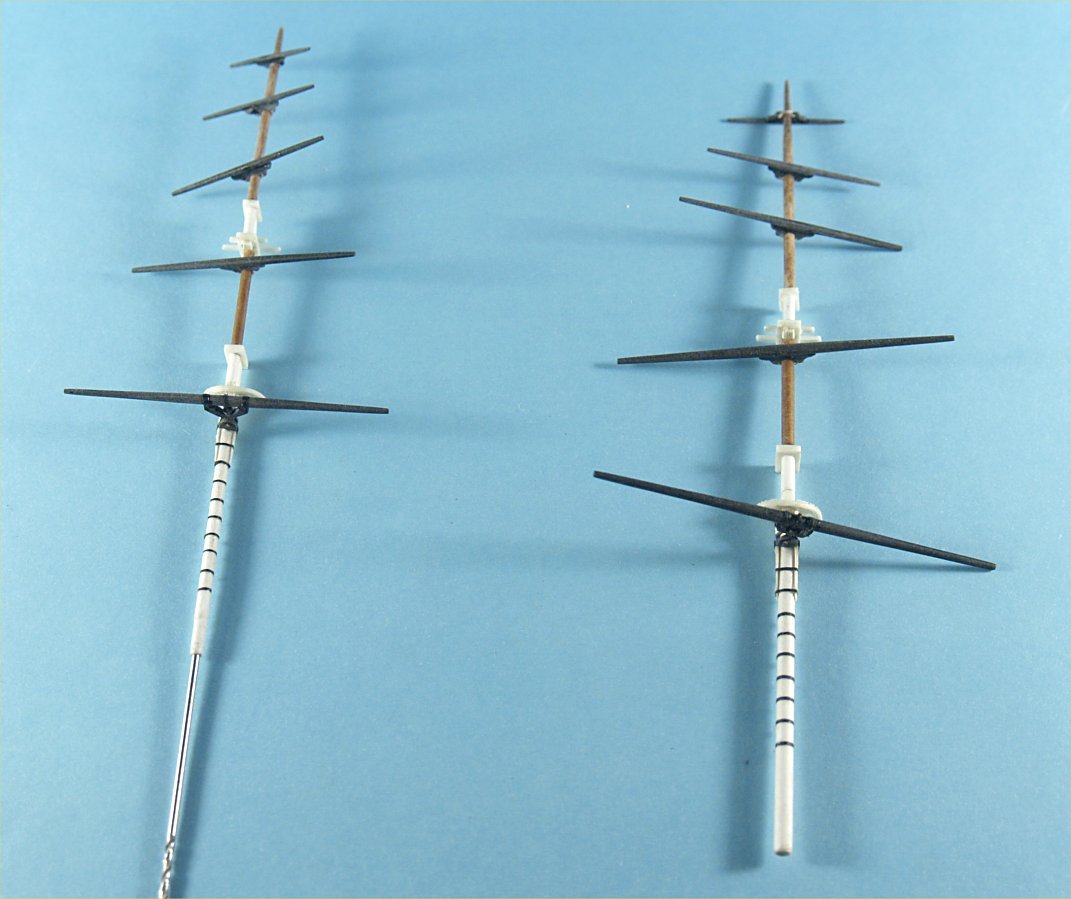
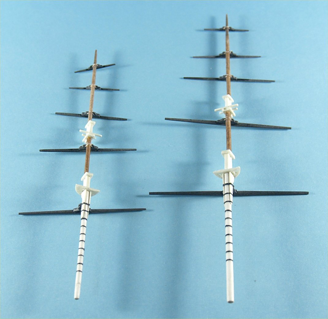
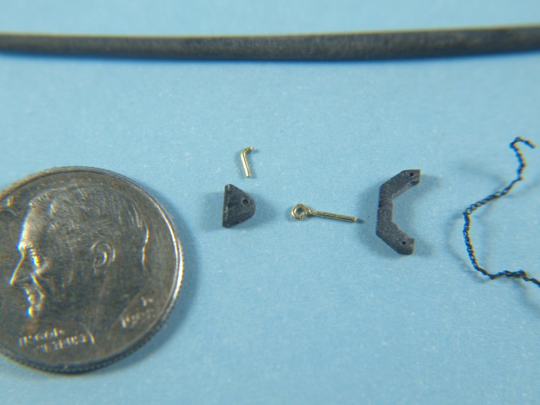
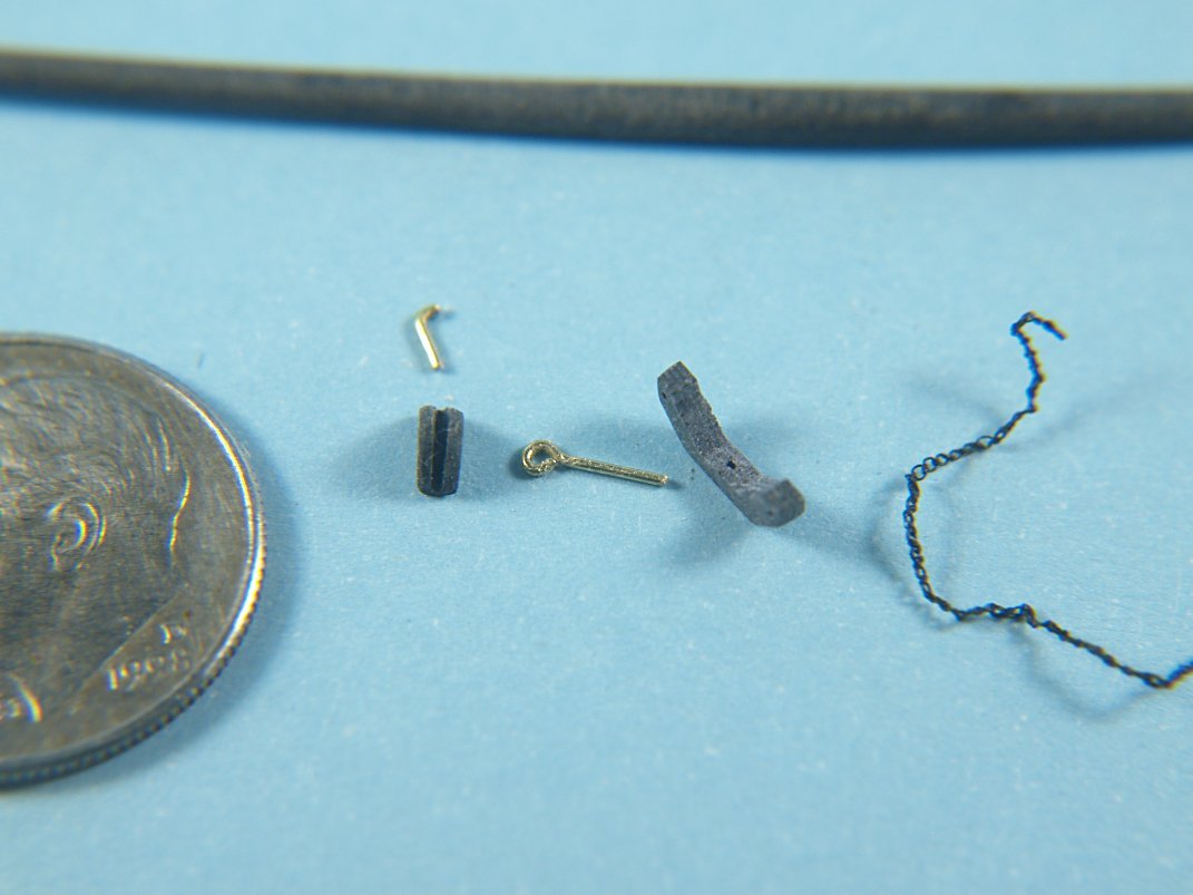
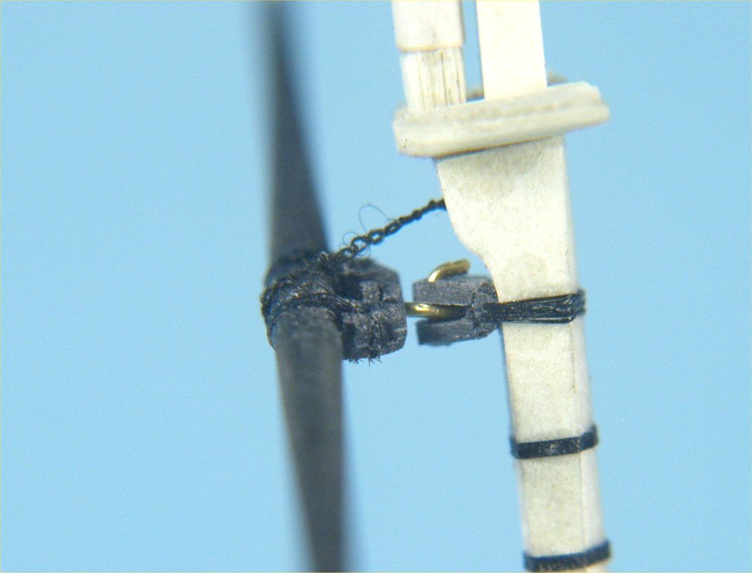
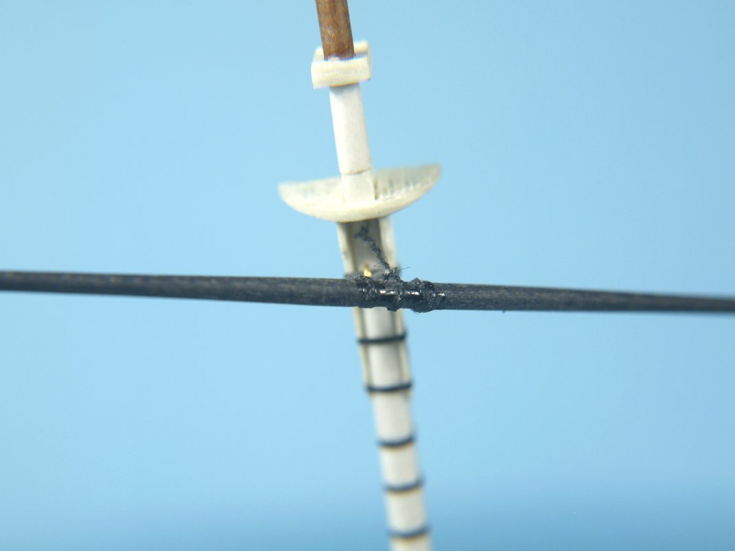
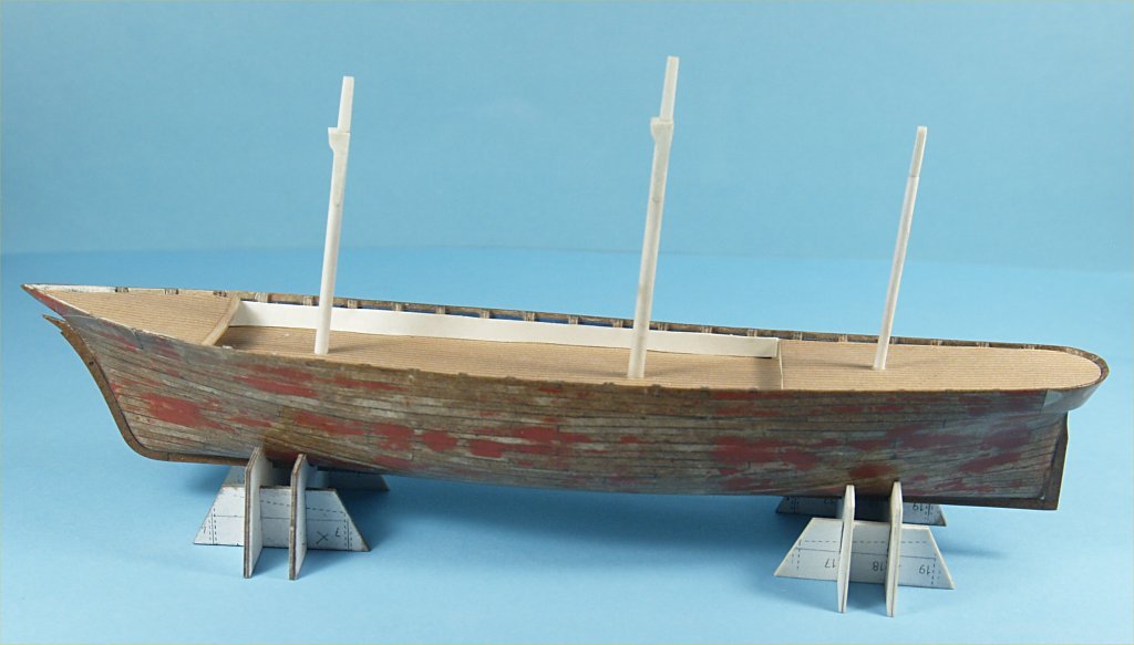
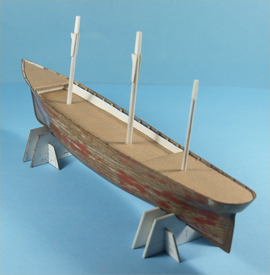
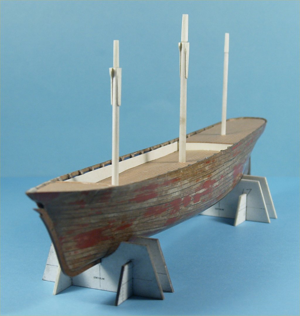
The experiments continued with finishing the colored planking on the second hull. The keel, stem and stern posts were added and covered with the copper colored card stock as well. The entire hull was then coated several times with thinned varnish. The following photos show the hull as it stands now. The majority of my time has been spent making the yards for the masts. It was found that laminating black construction paper worked out the best for their construction. Using liberal amounts of CA glue to laminate the paper, including soaking the outside of the layered pieces. From that point the laminated parts were treated much as I would making yards out of wood. I first sanded them into a square cross section as thick as the center of the yard, then slightly tapered the pieces on either end. Then sanded the yard into a hexagonal cross section throughout. Finally sanding the yard blank round in cross section. As with most of the other paper/card construction, it was necessary occasionally to apply a bit more CA glue when an unsaturated area was encountered. I also noticed that the laminated construction paper was a bit more brittle than most woods, so care was taken. All the upper yards used a simple fitting glued to them in order to attach them to the masts with a bit of fine thread. The crossjack and course yards were attached using a hanging bracket arrangement which was as close as I could get, at the scale and using the material, to what was shown on the plans. I also used two tiny pieces of brass wire in making the brackets, which allow those yards to swing partway around the masts. The final pieces to these yard hangers was fake chain, which was made from 8/0 fly tying thread. The fake chain was made by tying double overhand knot in the center of a length of thread around a #80 drill bit, which was fitted shank side down into a length of wood. The drill bit was then pulled up and removed from the thread loop. A length of the same thread was then tied through the loop and extended down the length of the wood, where it was held mildly tightly with a rubber band wrapped around both wood and length of thread. The thread was then pulled away from the reinserted drill bit, to keep the loop directly opposite the bit while tying a second double overhand knot. It was impossible to keep tying these knots exactly opposite each other, so the fake chain looks a bit "squiggly" when just laying there. It does look fairly realistic when pulled tightly. The fake chain was tied, with a small piece of thread through the first loop, to a small wire eye bolt. The eye bolt was made by twisting a piece of extremely thin wire around a #80 drill bit, using a forceps to twist until the wire broke. This eye bolt was glued into a hole drilled just below the mast top. The thread chain was then wrapped around the center of the yard, and a second small thread piece was inserted through loops in the chain twice. It took a bit of practice to choose the right loops to pass this thread through so that when a knot was tied into the thread it pulled to chain tightly around the yard center. The knots in the two threads were glued and the excess thread cut and removed. The following photos show the pieces and results of this portion of my experimenting. Anchor's A Weigh! John Fox III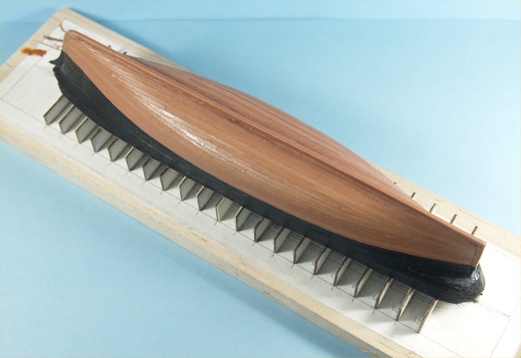

- 28 replies
-
- 11
-

-
Greetings Roger, The C. Reiss coal company was situated in Sheboygan, so perhaps they were used to unload coal there. There was still active coal unloading at least until I was a kid there, 1950's. There were huge piles of coal and a modern unloading crane system then. Not sure what the coal was used for, perhaps heating. Sheboygan was a very active port for Lake Michigan for many years in it's earlier history. Thanks for the reply, at least I can look for something specific, i.e. Brown Hoists. BTW, there were several high end furniture manufacturers in Sheboygan very early and again until I was a teen in Sheboygan. Also, at least one of the photos is accurate in location, other buildings in photo supply this information. Thanks again! Anchor's A Weigh! John Fox III
-
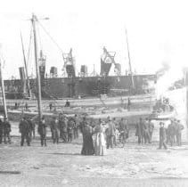
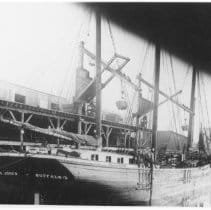
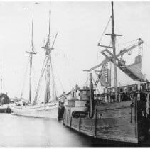
Greetings, Hope this is the right place to ask. I was looking at photos on a history site for my hometown of Sheboygan Wisconsin and saw these unloading cranes in the background. The dates seem to be the mid to late 1800's, unloading sailing ships, probably lumber transports. I was interested in more information on them, possibly for model building. Any help would be appreciated. Anchor's A Weigh! John Fox III
-
Thanks Allan! The sails for the model were made from some old, and stained, lamp shades. I don't know what material they were made from, but they looked the right color. I glued strips of folded over vellum drawing paper along all the sail edges, to keep them from fraying and adding strength to the points where holes were drilled to attach the mast and boom rings and the rings for the forestay on the fore sail. Anchor's A Weigh! John Fox III
- 9 replies
-
- 1
-
-
- Whistle Blower
- Finished
- (and 1 more)
-
Experiments in Card/Paper Modeling
John Fox III replied to John Fox III's topic in Card and Paper Models
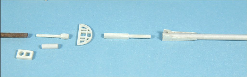
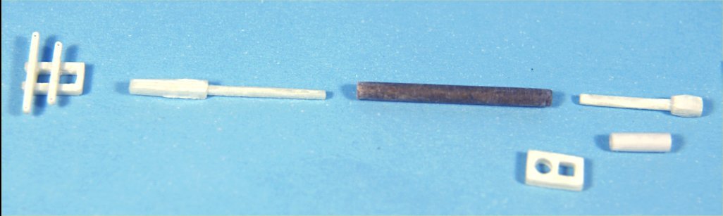
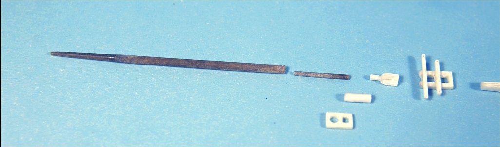
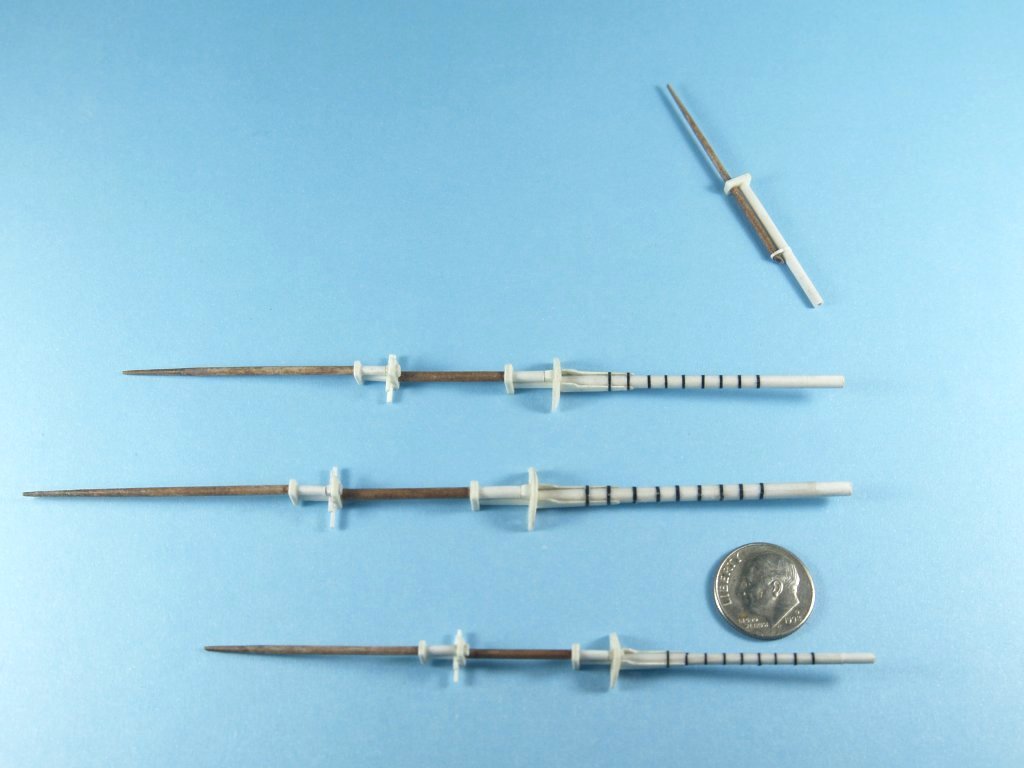
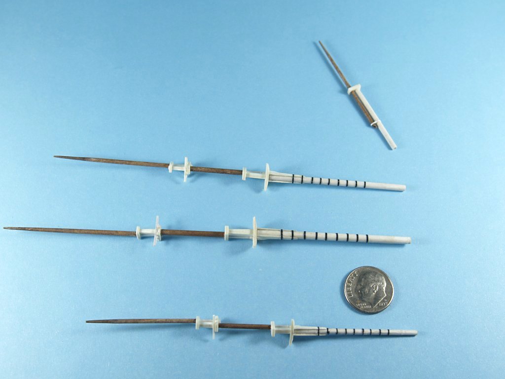
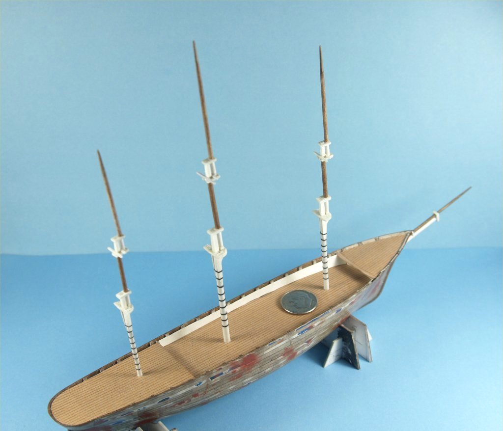
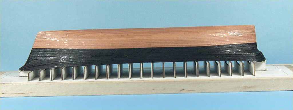
Work on the card/paper models continued with finishing up the masts and bowsprit/jib boom. The process for making the top and topgallant masts was similar to the work involved with making the lower masts. Various sized rods and tubes were wrapped with brown paper, using a tube or rod of the appropriate size to make the final paper tube a bit larger than necessary. The next steps were to sand the glued paper tubes to the proper size and shape. This work was very tedious as the CA glue applied to the outside of the tubing only saturated the paper for a few layers. As the sanding reached those unglued layers the paper because fuzzy and started to unwrap a bit. At those points an additional application of the CA glue was necessary. I found it necessary in many cases to have to repeat these steps quite a few times to get the tubes to final shape. The doublings for each mast overlap were made by making mast tops and trestle cross trees out of 3 or 4 layers of varnish saturated white card stock. I found that using the thinnest card stock worked best for these parts. Holes were drilled and cleared out to shape using an X-acto knife and #11 blade. The problems arose when using thicker card stock during the drilling and cutting phases of the work. The inner portions of the thicker card stock were not saturated with the varnish, and would start to separate as I drilled, or cut. This caused the drill bit to just push aside some of the inner card stock, which caused that portion of the part I was working to swell up and become thicker. Even when working with thinner card stock this happened to a lesser extent. What worked for me was to drill a few increasingly larger holes, then add a bit of CA glue into the hole. In this case I started with a #80 drill bit, then a size #76 followed by a #70 sized bit. Once these tiny holes were drilled I added the CA glue This hardened the area around the hole on the inner layers and helped stabilize the part. When larger holes were needed, larger drill bits were used, applying the CA glue to each hole after drilling. The same sort of technique was used when cutting and shaping the outside of white parts of the doublings, for much the same reason. Cutting to roughly the correct size and shape for a part, CA glued was applied to the edges, where the individual layers of the card stock were exposed. This work stabilized the part, and kept the layers from separating while further cutting and sanding to final size and shape. As with the doubling portion made for the lower masts, the tubes were connected together with pin like extensions of a part, or with card pins made from layers of stock glued together and then sanded round and to fit inside the necessary tubes. The white portions of the upper mast in each doubling was just a white paper tube, made like all the rest. The most difficult masts to make were the topgallant masts. In all cases I was simply unable to sand them down to a fine enough shape and size without their collapsing or unwrapping of the brown paper used. A fine pin of solid stock was glued into the tops of the tubes, with a bit sticking out the end. The work was similar to the other masts, sanding and applying glue as necessary. The following photos show the final results, including an exploded view of each portion of the total mast assembly. Note: While my purpose was to make an entire model from nothing but glue, paper and card stock, it would have been far easier and much closer to exact scale if I had been working with wood for masts and sheet styrene for top, trestle cross trees and mast caps. It took far longer to work with the paper and card stock, especially when having to use separate colors for the parts to keep from having to use paint. Simultaneously to work on the masts for the models was continued work on the second hull. The brown saturated card stock planks were added to finish the lower hull on the side shown in the earlier photo. The other side of the hull was then planked in the exact same manner. After planking was complete, as thin a coat as possible of epoxy was "painted" onto the entire hull surface with a thin, stiff brush. My previous attempts to thin two-part epoxy with rubbing alcohol never worked out right, the glue never cured. Not being thinned made applying a thin coat much more difficult in the end. Once the epoxy coating had cured, the entire hull was lightly sanded with 320 grit sandpaper, to even out the coating. As desired, the coating hardened the card stock surface making it far easier to sand and even things out. In an effort not use paint on this hull, I decided to use two colors of card stock. I found a moderately copper looking card stock at a local shop, and used black construction paper for the second color. Both stock were saturated with thinned poly varnish and allowed to dry. A wooden jig was then constructed to make it easier to cut 1/16" wide strips from both colored stock. At that size it was a bit out of scale, about 2' wide. I found that there is a vast difference between the construction paper and the copper colored card stock at this point. The cut edges of the card stock were white, meaning the color was only applied to the outside surfaces, where as the construction paper was solid black through it's thickness. I did a little research online to look for card stock that might work better, what I found was that there are two types of card stock. The "normal" stock has color only on the surfaces, while the "solid core" card stock had color the same as construction paper. Unfortunately, the solid core stocks were much heavier and thicker, so I decided to use what I had. While researching the stock, I did find that there are some copper card stock that looks just like metal copper, but none that were solid core. Another thing I found with my experiment was that the varnish fully saturated the construction paper, but not the card stock. The color on the outside surface of the card stock seems to seal it allowing minimal saturation. This led to the black paper being much stiffer, harder and brittle, but the colored stock being the opposite. The colored paper easily bent to fit against the first planking layer, while the black paper would crack and break if attempting to force it to shape. The second hull was now planked, using the white plank line on the first plank layer as a guide to separate the copper lower hull from the black upper hull. The effect of this planking looks quite reasonable from any distance, but close up one can see the white edges of the copper stock in areas of extreme curvature of the hull. There are also a few places where the fit wasn't quite right, and a small portion of overlap of the previous plank installed happened, which left a raised portion of that copper colored plank. There are also a few spots where the planks left very slight gaps, allowing the brown planking beneath to show through. In the end, while the second planking definitely is not as good as I wished, it does do a reasonable job of duplicating a ships hull. I will attempt to keep the errors from the first side planking to occur on the second side as I work. Were I to do it again, I might make the hull form a bit smaller, so that the much thicker solid core card stock could be used for the colored planking without compromising the scale. I may attempt to alleviate the problems of the copper colored planking by lightly sanding the copper stock to get rid of raised areas and then use a green colored thinned paint "wash". My thinking is that it would look somewhat realistic, but would compromise my idea of not using paint. The following photos show the planking work to date. There are some areas that shine on both planking colors, these are areas where it was necessary to apply some CA glue to the outside of the planking. Anchor's A Weigh! John Fox III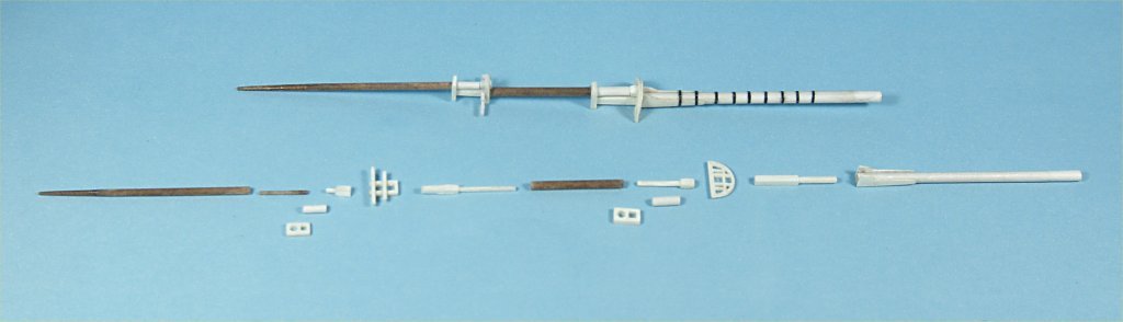
-
Thanks Kev! I do try! <Grin> I've always been fascinated by the sandbagger yachts, as a small boat sailor they seem intimidating with so much sail. Anchor's A Weigh! John Fox III
- 9 replies
-
- 1
-
-
- Whistle Blower
- Finished
- (and 1 more)
-
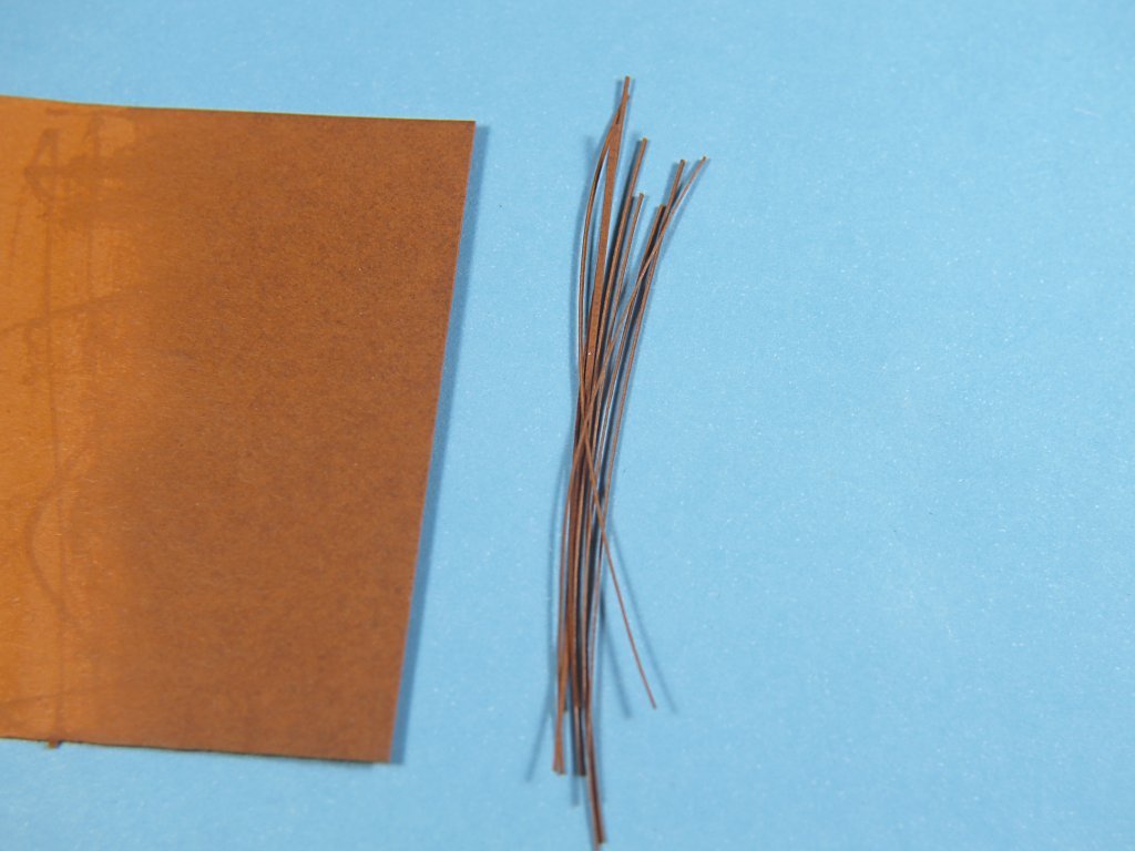
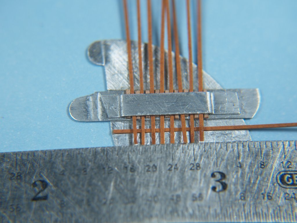
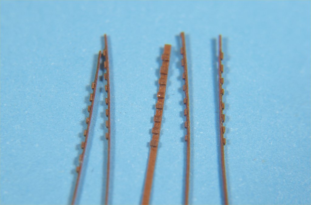
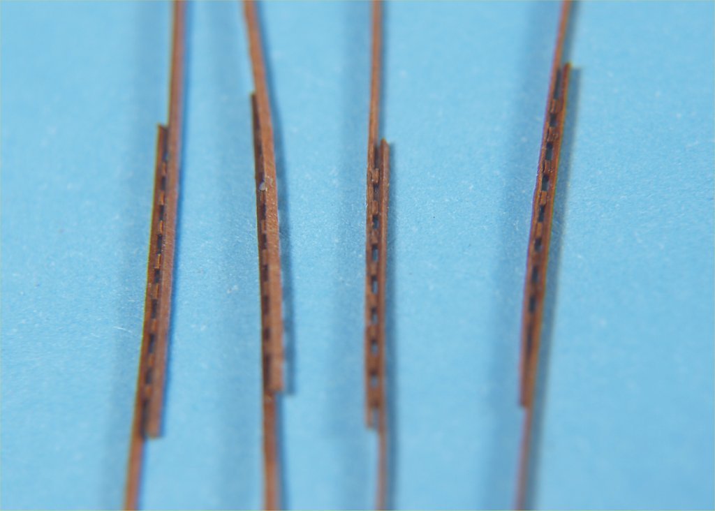
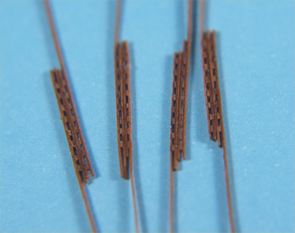
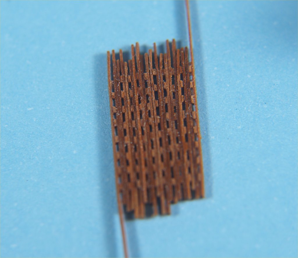
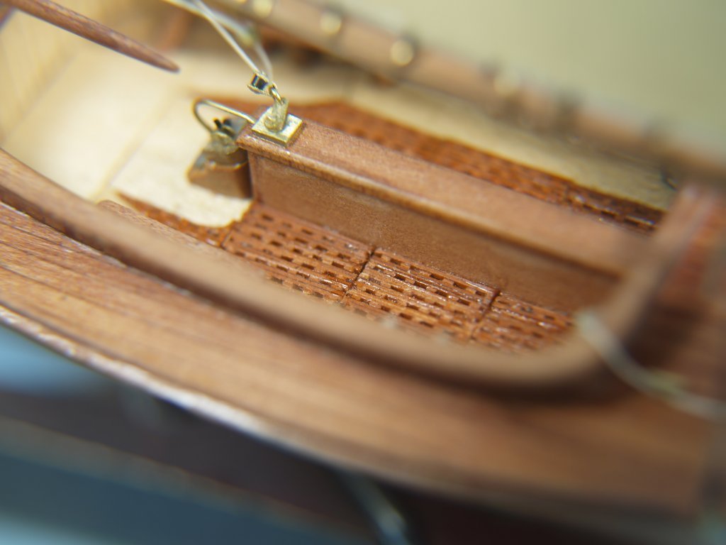
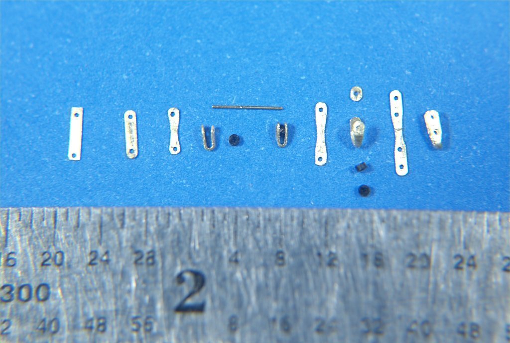
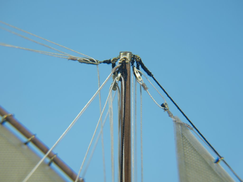
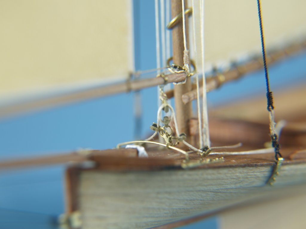
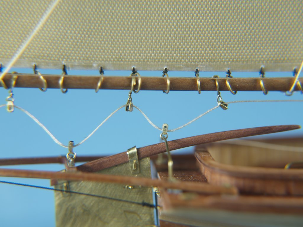
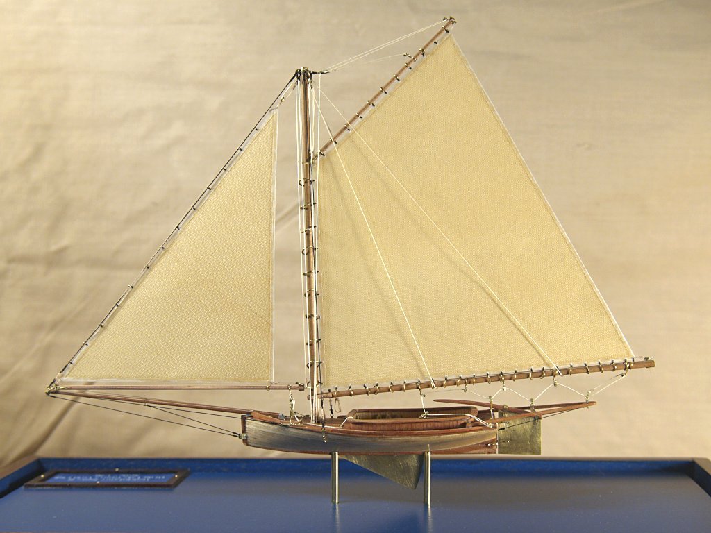
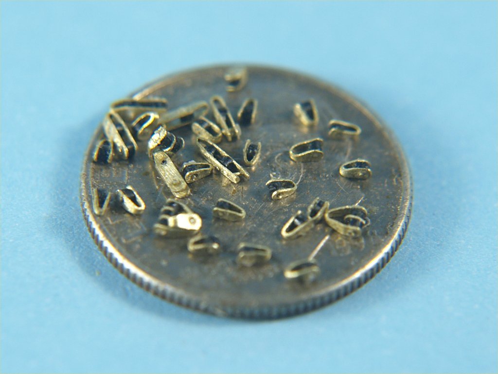
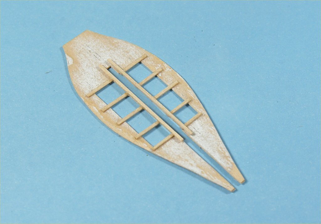
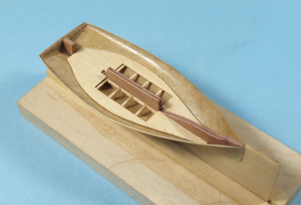
The next item on the Whistle Blower agenda was making up the gratings for the cockpit floor. I used some card stock from a manila folder, which I stained to make it a bit darker brown. I cut the stock into strips just a bit under 1/32" wide, a lot of strips. I then made up a jig from aluminum and thin wood strips to hold the card stock strips at set distances apart. The stock strips were about 3" long and fed into the jig so that about 1/4" stuck out. I then slid another stock strip under the strips in the jig, used a metal rule placed just beyond the single strip, to hold the jig strips down tightly to the cross strip. I then applied a tiny amount of CA glue to the jig strips, to lock them to the cross strip. I used a piece of fine wire to apply the glue. I then cut off the jig strips, moved the cross strip away from the jig and trimmed both sides of the jig strips on each side of the cross strip. I made up quite a few of these strips with square "knobs". A second card stock strip was then carefully glued on top of the knobs, as evenly as I could to match the strip below the knobs. I made up many of these combination strips. I then carefully glued the doubled stock strips with knobs together to make double strips, and again glued those together and etc., until I had made up a series of these as wide as needed to fit the grating openings in the cockpit floor. At this point the grating was a bit too thick, and due to difficulty of gluing the combo strips together, not totally even on front and back surfaces. To finish the grating pieces I lightly sanded both sides of the grating pieces to get them even and thin enough for the model. The pieces were then cut to fit the grating openings in the floor, gluing them on top of the cross pieces glued beneath the floor piece. The following photos show the progress on these gratings. Note: It was at this point that I found that the model was too wide on the starboard side, and decided to make a new plug and paper hull. To make the second plug I used more buttock cut pieces to laminate the hull, which made it far more accurate in the end. Work on the Whistle Blower II continued with finishing the cockpit. Unfortunately, I did not photograph this process, but will explain the work. The inside cockpit walls were made by gluing 1/16" wide maple veneer strips vertically from the floor to 1/4" above the deck. The outside of the raised ring around the cockpit was made by gluing slightly wider strips of cedar to the outside of the maple pieces sticking above the deck. The top of this wall was sanded even and to match the sheer of the deck. The cap rail was made from 3 thin pieces of cedar veneer, glued up with the center piece grain running perpendicular from the two outer pieces. The shape of the cap rail was then cut and sanded, and the rail glued to the top of the cockpit walls. Another strip of cedar was glued on top of the keel well to match the views of the Tattler II in the photos I found. The mast, boom, bowsprit and framing extending off the stern of the model were made from maple. The bowsprit was made from two thinner pieces, glued together with the curve by applying the glue and then bending the pieces until the glue cured completely. The keel and rudder were cut from .015" thick brass sheet. The mast and boom rings were made from various diameters of brass wire, wrapped around drill bits, cut off individually, and then flattened to match the ends. I did not solder or glue the ends together, which led to some instances of the thread attachments to the sails slip through the tiny gap in the rings occasionally. The sails for the model were made from some old, and stained, lamp shades. I don't know what material they were made from, but they looked the right color. I glued strips of folded over vellum drawing paper along all the sail edges, to keep them from fraying and adding strength to the points where holes were drilled to attach the mast and boom rings and the rings for the forestay on the fore sail. The last items constructed for the model were the blocks for the rigging. I used 0.005" thick brass sheet and cut 1/32" wide strips. Fine files and 320 grit sandpaper were used to shape the individual pieces, after drilling the appropriate holes for the type of blocks needed. The strips were then folded over, matching the holes from side to side. A piece of insulation from very fine electrical wire was cut into 1/64" wide bits for the sheaves of the blocks. A piece of fine wire was then cut into short lengths and pushed through both holes in the brass, with the plastic sheaves between them. A tiny amount of CA glue was then applied to the wire ends on both sides of the blocks. The following photos show pieces of the blocks and a few of the blocks as used in rigging the model. This article was written more to show some of the materials and methods I used to build the model, than to show a complete building history. The entire project was really my attempts at experimenting to find ways and means to make the various miniature parts than to build an actual model. That is the reason I did not photograph all the building steps used. In the end, I decided to follow through and finish building a model. The photos that I was able to find of the Tattler II did show that the planked hull was covered with fiberglass or carbon fiber cloth, and later painted. I decided I liked the planked hull look, so went with that for my model of Whistle Blower II. The last photograph shows my finished model of Whistle Blower II. I hope that others can find my experimenting useful for their own builds. Anchor's A Weigh! John Fox III
- 9 replies
-
- 12
-
-
- Whistle Blower
- Finished
- (and 1 more)
-
Kit Review Paper Shipwright Kits: A General Overview
John Fox III replied to ccoyle's topic in REVIEWS: Model kits
Thanks Chris! Very informative and interesting topic. Anchor's A Weigh! John Fox III -
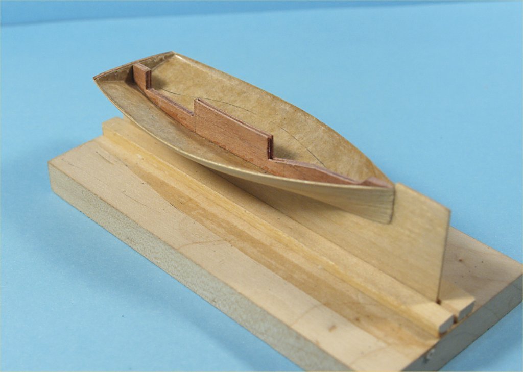
Once the planking was completed a slot was cut in the paper hull using the gap in the outer keel as location for this slot. Drill bits and pin vice were used for location, and a X-acto knife and #11 blade used to clean up the slot from inside the hull. A piece of maple veneer cut to fit the length of the slot, but long enough to extend well beyond the keel below and above the inside of the hull. This piece was inserted into the slot as a locator for installing the inner keel piece. The photos will show two different inner keel pieces, the maple one was used on the first hull, which later turned out to be inaccurate in that the plug was wider on the starboard side than the port side. Unfortunately, I didn't notice this until later in the building process, and I then made the decision to build a second hull. The inner keel piece was also cut in such a way as to form the sides of the keel well, and low enough to be able to fit deck frames above it. The second inner keel piece was made from cedar, to more closely match the coloration of the real Tattler II. A piece of paper was cut, by trial and error, to fit inside the hull at the level of the floor of the cockpit. This paper template was glued to some maple veneer and wood cut out and trimmed to fit. Once the floor piece was cut out, the paper was then sanded off the wood and lengths of maple veneer were cut into strips and glued across the bottom of the floor piece to rest the grating on top of. The following photos show the work so far. Work on the hull progressed by cutting and fitting basswood deck beams. The beams were cut 1/16" wide and about 3/16" deep. The spacing of the beams was completely arbitrarily, other than having the front and rear of the cockpit area located with beams. Additional deck framing was added between the deck beams, to keep the beams from being rotated while sanding to fair the deck. Again, the locations were mostly arbitrary other than making sure the cockpit sides were located via the additional framing. Areas between framing pieces where fittings would be attached to the hull, and the round corners of the cockpit area, were filled with solid pieces of 1/6" thick wood. This was done to give a solid attachment points for various fittings and the bowsprit. The deck of the first model was planked with maple veneer sanded down to .015" thick and cut to 1/16" wide, the second model was planked with cedar cut and sanded the same dimensions. CA glue was used to plank over the entire top of the hull. After sanding the deck planking and cutting the planking 1/16" outside the top of the hull, a template of the cockpit opening was used to trace that outline onto the hull. A series of drill bits and pin vice was used, just inside the cockpit outline, to initially open this area. A knife was then used to cut away all the frames, and the outside edge of the cockpit sanded. The following photos show this work on the model.
- 9 replies
-
- 7
-
-
- Whistle Blower
- Finished
- (and 1 more)
-
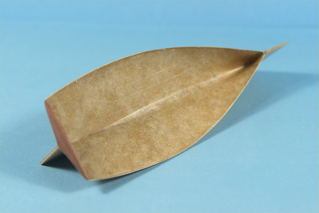
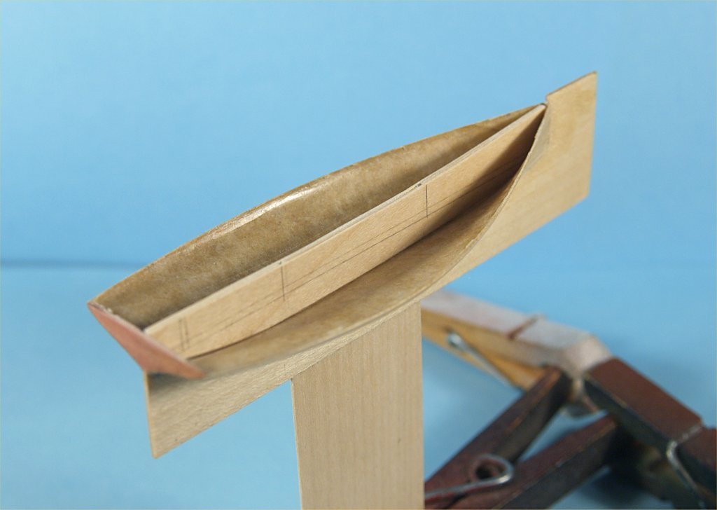
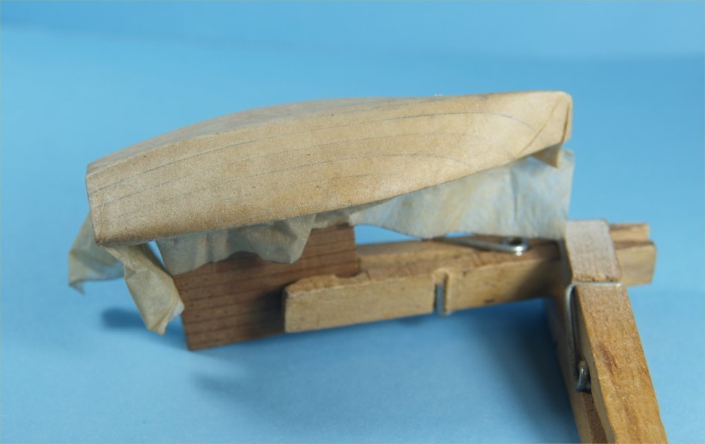
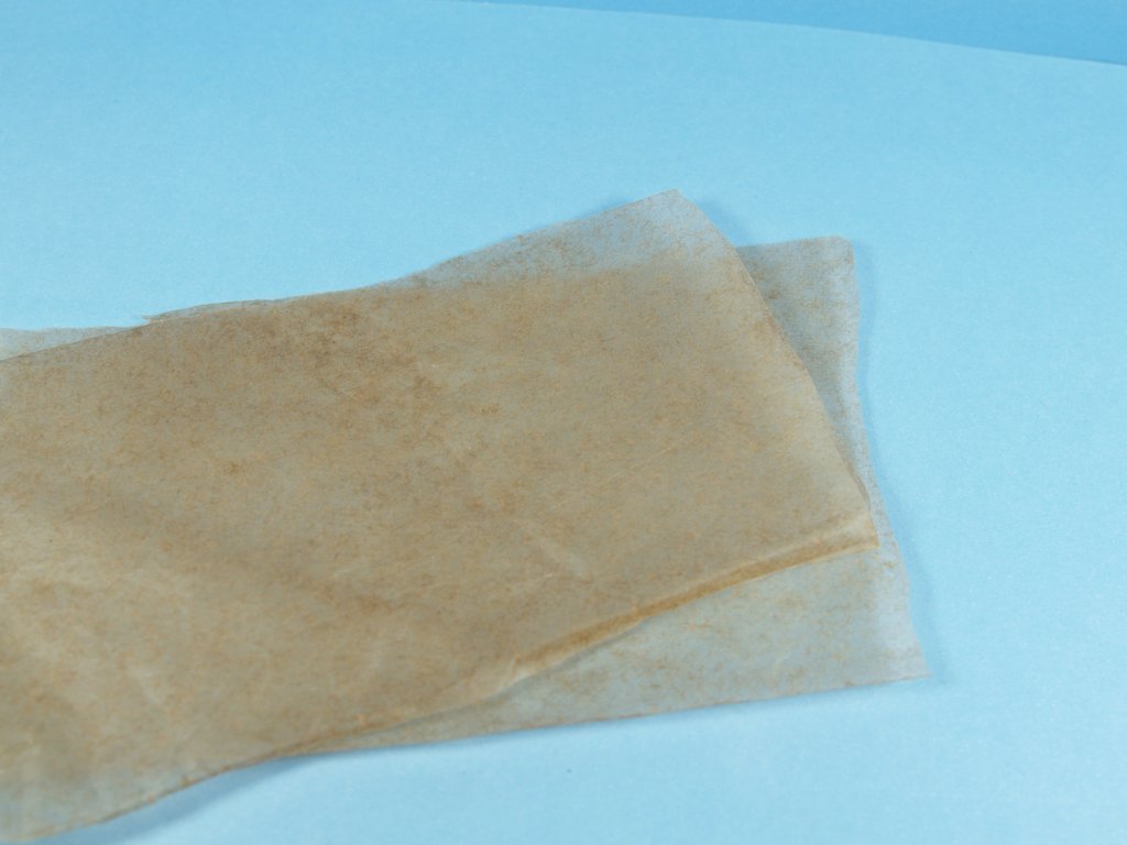
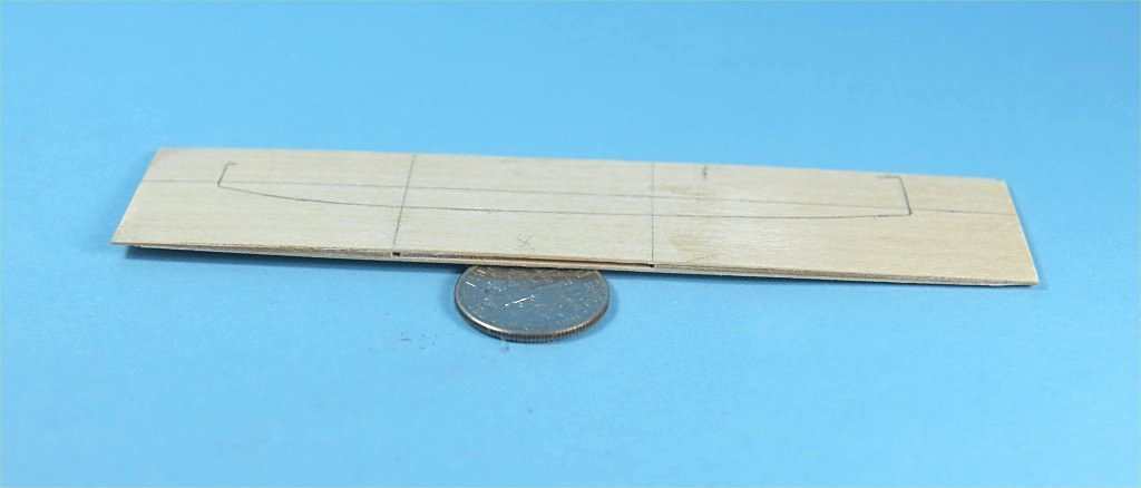
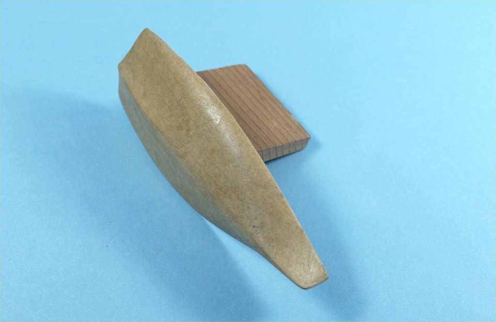
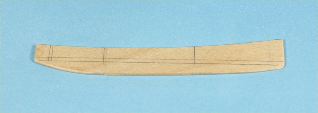
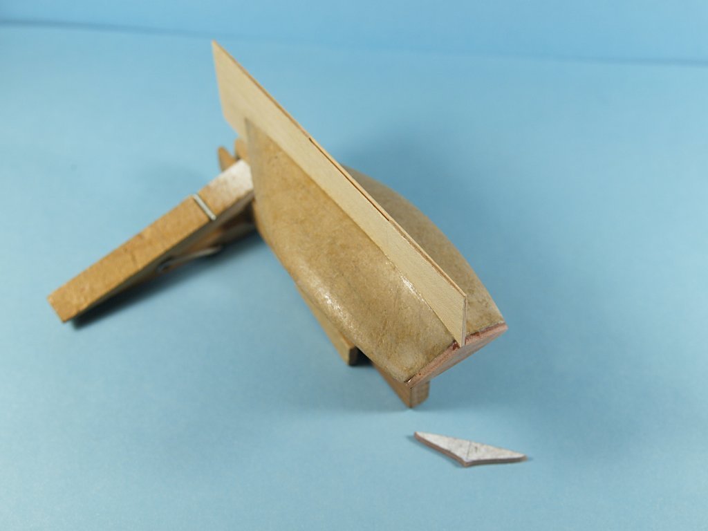
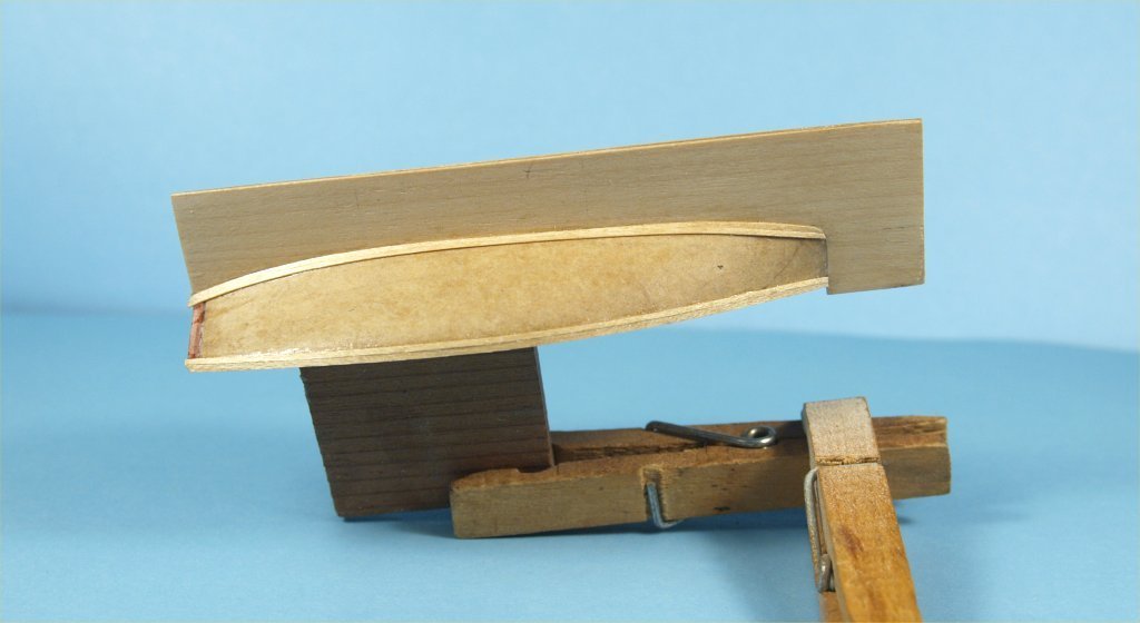
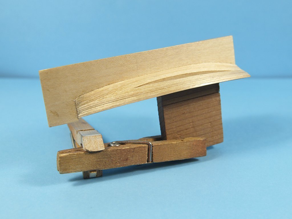
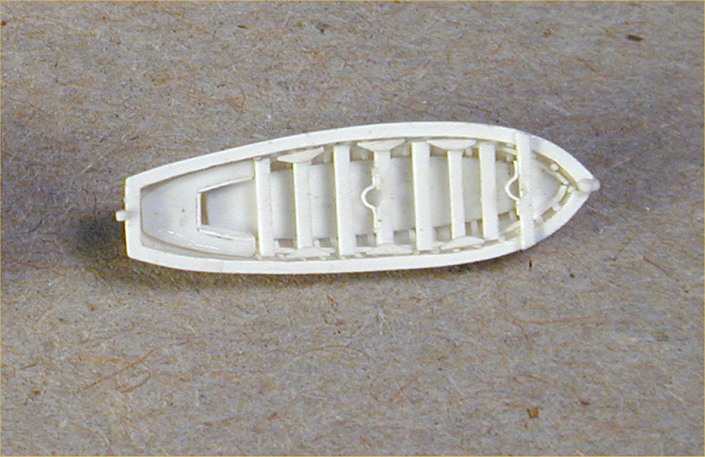
This is a build log of my attempts to build a 1:96 model of the sandbagger Whistle Blower II. The primary reason for building this model was to test out whether my paper mache method for building miniature ship's boats could be used to build the foundation for hulls of larger models. I will start with a description of my ship's boat hull methodology, by utilizing cigarette papers and thinned PVA glue. Most of my ship and boat modeling has been of miniatures, anything from 1:200 to 1:1200 scales. At those scales making realistic ship's boat hulls with adequate details is fairly difficult. Once I found the method described here, I was most pleased with the results and used it for almost all such modeling efforts. The basic idea was to carve, sand and seal a wooden plug that matched the inside dimensions of the desired hull shape. The plugs were sealed multiple times with thinned poly varnish, 50/50 mixture, to make them completely sealed. I needed the plugs to be sealed enough that water would not penetrate. The next step was to drill a hole in the middle of the top of the boat plug, and gluing into it a toothpick, to hold the plug during further work. The plug was then inverted, and wooden clothespins used to hold the plug in that position. I then used a piece of cigarette paper, cut to fit completely over the outside of the plug, with a bit to spare. This paper was then dipped into a pool of thinned PVA glue, dragged over the edge of the container holding the glue mixture, and centered over the bottom of the plug. A rounded ended, well sealed wooden toothpick was then used, with a rolling motion, to carefully mold the fragile whetted paper to the surface of the plug. At the stern and bow areas the paper was folded over itself in order to get it to mold tightly to the plug surface. I left the paper to dry for 24 hours, then repeated the process again. The next time I added a paper layer I would fold over the paper in the opposite direction, in order to even out the thickness of the paper layers as much as possible. After four layers of paper had been added to the plug, I carefully cut the excess paper at the top of the bulwarks, i.e. bottom edge of the inverted plug. I would then lightly sand the paper in those areas of the bow and stern where the folding over left much thicker areas of paper. The entire outside of the paper hull was then sealed with thinned ply varnish and sanded lightly again. The paper hull was then "popped" off of the plug. This method worked extremely well, especially when I had to make many copies of the same hull for models I built multiple copies. Sheet stock of styrene plastic to add details to the insides of the ship's boat hulls. The following photos show the process used. I knew that to upscale this method to a much larger scale model I would need a hull shape that had no tumblehome in the hull. Looking over my CAD ship and boat drawings I decided that the sandbagger hull would be the perfect example to try out my idea. I had previously made small scale models of the Susie S., plans from Chappelle's The History of American Sailing Ships, so I had some CAD drawings already made which could just be printed to a larger scale. For those readers who may not be familiar with the sandbagger yachts, they were popular racing yachts in the late 19th and early 20th century in the New York and Boston areas. They were very beamy, low draft, fairly short hulls that carried a very large sail surface for their size. They had long bowsprits and framed extensions off the stern in order to handle the large sail sizes. The name of the type was derived from the fact that 40lb. - 50lb. bags of sand were moved from side to side on the boats when tacking, in order to get the fastest speeds possible. In most cases dockyard workers were hired to do the heavy lifting during races. I was also interested in building a model of a vessel a bit "closer to home" than all my other builds. I live in central northern Wisconsin, and luckily found that there was a modern sandbagger on Lake Geneva, WI, called Tattler II. The original Tattler was a rather famous yacht that won many races on that lake, and was eventually made the icon for the Lake Geneva Yacht Club. The modern Tattler II was commissioned to be a copy of the original, with the stipulation that it be easier to sail. I found about a dozen photos of Tattler II searching the internet, about half of them at various early stages of construction, and just a few at later times while sailing. I contacted the builder for plans, but was told that under the contract to build the yacht was a stipulation that the plans not be sold or distributed. I decided I would take my Susie S. plans and make adjustments to match as closely as I could the photos of the Tattler II. I also decided that the owners might object to using that name on my model, since they made the stipulation about the plans, so went sideways a little and named my yacht model Whistle Blower. Interestingly enough, partway through my build of the model I found an error that simply would not allow me to finish the first hull made, so made a second and called it Whistle Blower II. Starting the model I made up a wooden plug of the appropriate size and shape for my paper hull. As with the ship's boat hulls, the plug was well sealed and glued to something to hold the hull upside down. At first I tried covering the plug with the largest cigarette papers I could find, but it became too difficult to cover properly with whetted papers as it took more than 4 papers. I also decided that it would be much more difficult to sand to an even thickness with all the overlapping the papers needed. Instead of the papers, I tried using tissue gift wrapping paper. At least a portion of the inside of the model hull would be visible in the finished work, I used tissue paper that was stained with a mahogany colored wiping stain. The tissue paper worked well, I could cut pieces just large enough to cover the entire plug in one piece. The work on the hull progressed much as described for the boats above. The following photos show the plug and work in progress. Six layers of the stained tissue paper were used to cover the plug for my final hull. I wasn't at all sure if the paper hull would withstand the work needed to remove the hull from the plug, so decided to plank the outside of the hull with thin strips of maple veneer. The Tattler II photos show that thin planks were used to form it's hull as well. I have a supply of 1/32" thick maple veneer which I sanded down to 0.01" thick for the hull planking. I cut the veneer to 1/16" wide planks and used cyanoacrylic glue to apply the planking. I used the same veneer for the hull of both models hulls built. Before beginning the planking I made up an inner and outer keel piece from the original maple veneer. The sandbaggers had drop keels, so needed the keel pieces I made to include the opening for the drop keel. I made up the keel pieces with the inner portion of the 3 layers with the grain running vertically, and the outer layers horizontally. The outer keel was added before planking started. The outer keel was made much deeper than necessary, to be used to hold the model while planking and during further work. A solid cedar stern was cut and glued to the paper hull, partly to match the color of the Tattler II, and partly to have a solid wood surface for the ends of the planks to be glued onto. I planked the hull starting at the keel and the sheer, and worked inwards, cutting planks to fit as I went along. The following photos show this work.

- 9 replies
-
- 7
-
-
- Whistle Blower
- Finished
- (and 1 more)
-
Experiments in Card/Paper Modeling
John Fox III replied to John Fox III's topic in Card and Paper Models
It may very well finish up as a completed model, I just don't know that yet. All I can do is keep trying and see how things work out. Anchor's A Weigh! John Fox III -
Experiments in Card/Paper Modeling
John Fox III replied to John Fox III's topic in Card and Paper Models
See the written portion and photos above, it explains and shows how the squared portion of the masts, at the doublings, is made. I am not writing up these experiments to excite interest in card modeling, in my experience many people don't think something is possible in modeling. I've built literally 100's of miniature ship models over 40 years as a professional, and am at a point where I experiment with different things just to see what is possible. I am very determined, and usually don't give up until I've exhausted everything I can think of to make any part from any materials. I only post my experiments because it might impart the idea to not give up, but keep experimenting in mind when modeling. You might find you can do/make things you never thought possible. I do not plan to paint any part of my experimental clipper models, there are problem areas such as the darker areas on the white masts shown above, where the glue between paper layers comes through. I know other card modelers use paint, and colored foil materials for their planking. And of course wood for spars and to stabilize the interior structure. If that "works" for a modeler, fine. I just want to find out what might be possible if one uses nothing but card and paper stock, and if I take it that far, thread. Wood spars would of course be much easier, and far faster. I've made countless 1000's of them in my time. Again, just want to see how far the idea of card stock and paper will take me. Anchor's A Weigh! John Fox III -
Experiments in Card/Paper Modeling
John Fox III replied to John Fox III's topic in Card and Paper Models
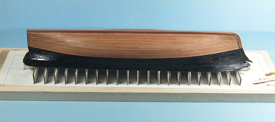
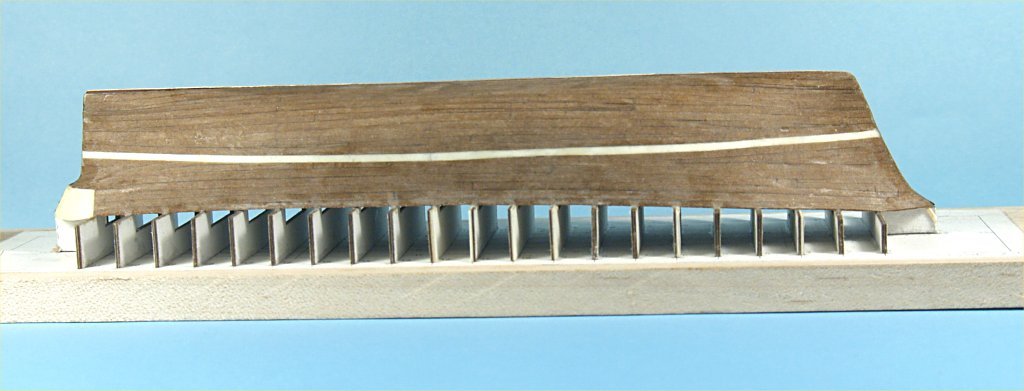
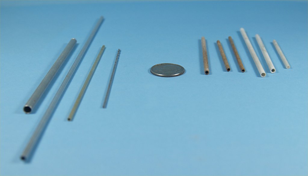
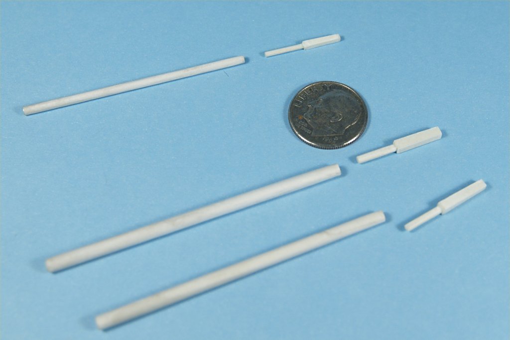
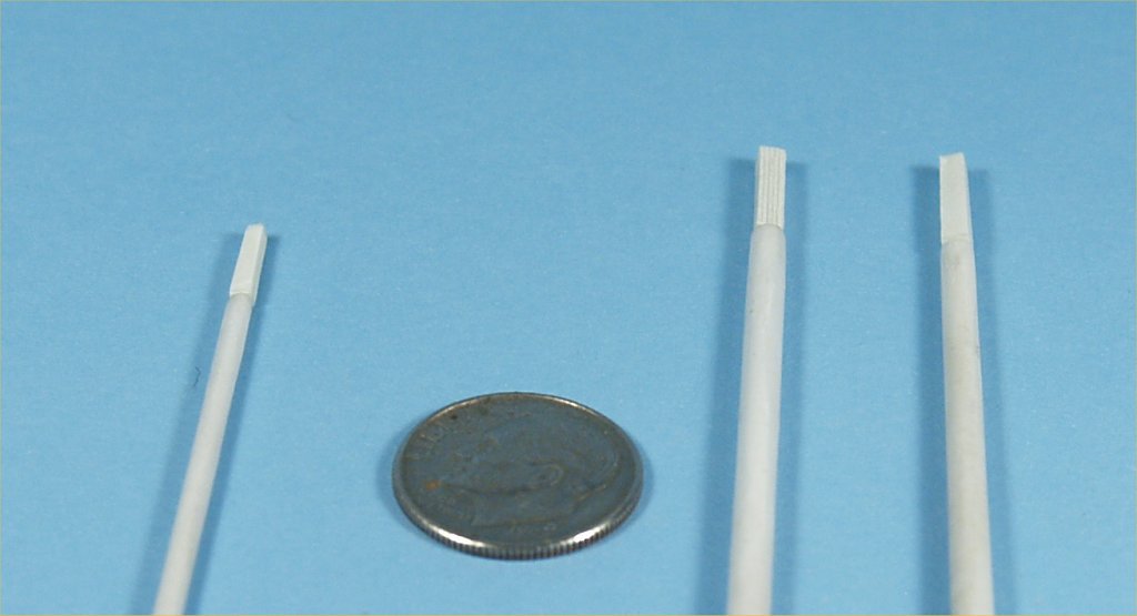
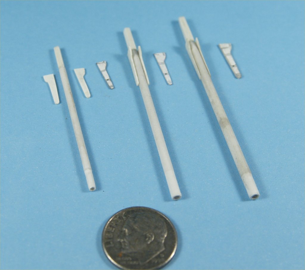
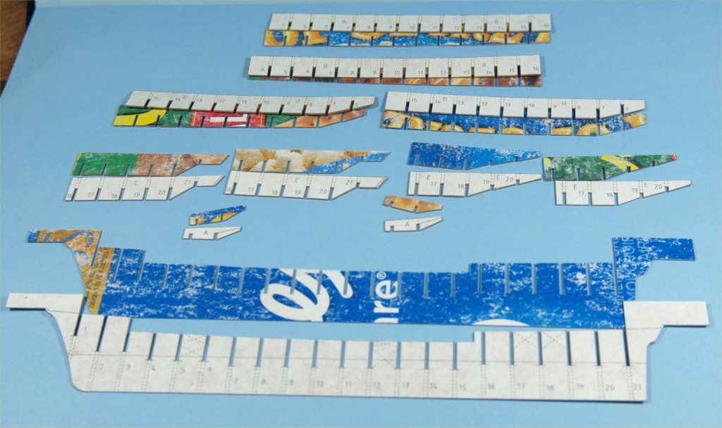
Continuing with my work on experiments in cardboard/paper modeling..... Work on the second hull continued with the start of a first layer of planking. This time I used well saturated cardboard that was thinner than that used on the first hull. These planks were stiffer, but also much more brittle. I also changed things up a little by using a white card stock, also saturated with thinned poly varnish, to delineate the waterline. The following photos show this work in progress. One thing to note is that this time I did not fill in the bow and stern areas with solid card stock, not sure if it was a good idea or not, it make planking much more difficult. One thing I am trying to accomplish with these experiments in card modeling is to see how far one can go with only cardboard and paper. I expect at some point I won't be able to take it all the way, but the only way to really find out is to experiment. While working on the planking for the second hull I would take breaks from that work to try out a method to make spars for the models. I used a variety of different sized aluminum and brass tubing, as well as a long miniature drill bit in my efforts. I wrapped very thin paper around the largest tube in my selection, carefully rolling the paper between my thumbs and forefingers on both hands around until the paper was tightly wrapped. I then let up slightly, removed the larger tube and inserted the next smaller tube and continued. I repeated this process until I had a tube that was slightly larger on the outside than the desired finished mast. While holding the paper tightly to the last tube/bit I applied CA glue to the point where paper ended, working from one end of the tube. I then slid the paper tube nearly off the tube, and saturated the entire outside of the tube with the CA glue. I then removed the paper tube from the brass/aluminum tube or drill bit, and used a thin sliver of bamboo to seal and harden the inside of the entire tube by dipping the sliver of bamboo into the thinned varnish and letting it drip from the tip of the sliver into the open end of the paper tube. I repeated this three of four times on each end, then pushed the bamboo sliver in and out to clear any excess varnish. I wanted the inside of the paper tube completely sealed, but also completely cleared so that the metal tube/bit could be reinserted. At this point I put the metal tube/bit back into the paper tube and sanded the outside of the tube to attempt to get the desired taper. After sanding a bit I would reach a point where the CA glue had not saturated and the paper would start to fray a bit. I would then add more CA glue to the outside of the paper tube, and continue again with the sanding. I repeated this process until I had the desired spar shape. Though the photos included below only show the finished mast parts for one model, I made many more tubes. I had to make up tubes that would be thick enough to be stiff at whatever desired size I needed, but that meant cutting many pieces of paper and gluing them up to determine the length of paper that worked best, i.e. not too much paper to make the tube walls too thick, but enough to make the tube as stiff as possible. The next portion of the work was making up layered solid pieces of card stock, to add to the tops of the mast tubes. These layered pieces were made to be as thick as the tops of the paper tubes, masts in these cases. These pieces are designed to make up the mast doubling areas. The layered pieces were then measured so that they were about twice as long as the mast top area, then one portion was cut and sanded into a solid, round stem. This stem portion would be inserted into the paper tube top end. Then they were sanded and cut into the proper side and shape for the mast tops. Work on the masts continued with making and adding the cheeks. I first made a template by gluing a cutout from the plans onto a single layer of card stock. I used that to trace the shapes onto a thicker layer of card stock, and cut them out. I glued them to the masts, then sanded a taper into the cheeks, thinner at the bottom to full thickness at the top. While doing this work I also glued the card decks onto the hull. I did glue a card stock beam to the underside of the stern edge of the forecastle deck. The holes for the masts were then cut out of the decks. I also glued pieces of thinner white card stock to the insides of the bulwarks. I used thin paper pushed tightly to the deck and bulwarks to get the curved shape needed, then transferred that to the final card stock. The following photos show the work on mast cheeks and first hull with decks. Anchor's A Weigh! John Fox III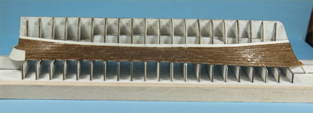


-
Experiments in Card/Paper Modeling
John Fox III replied to John Fox III's topic in Card and Paper Models
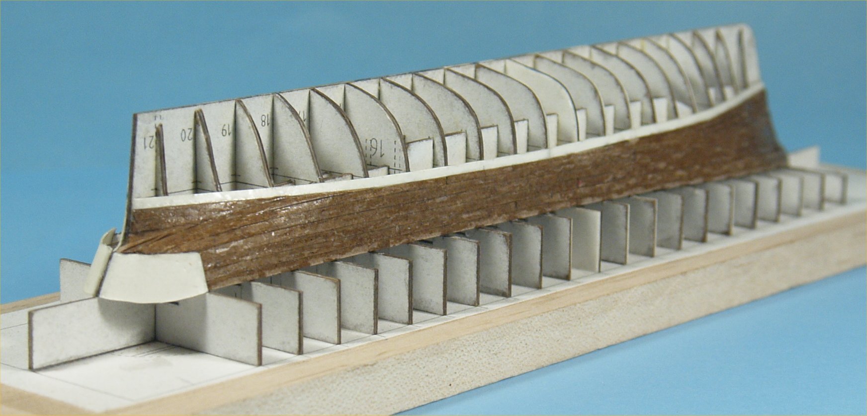
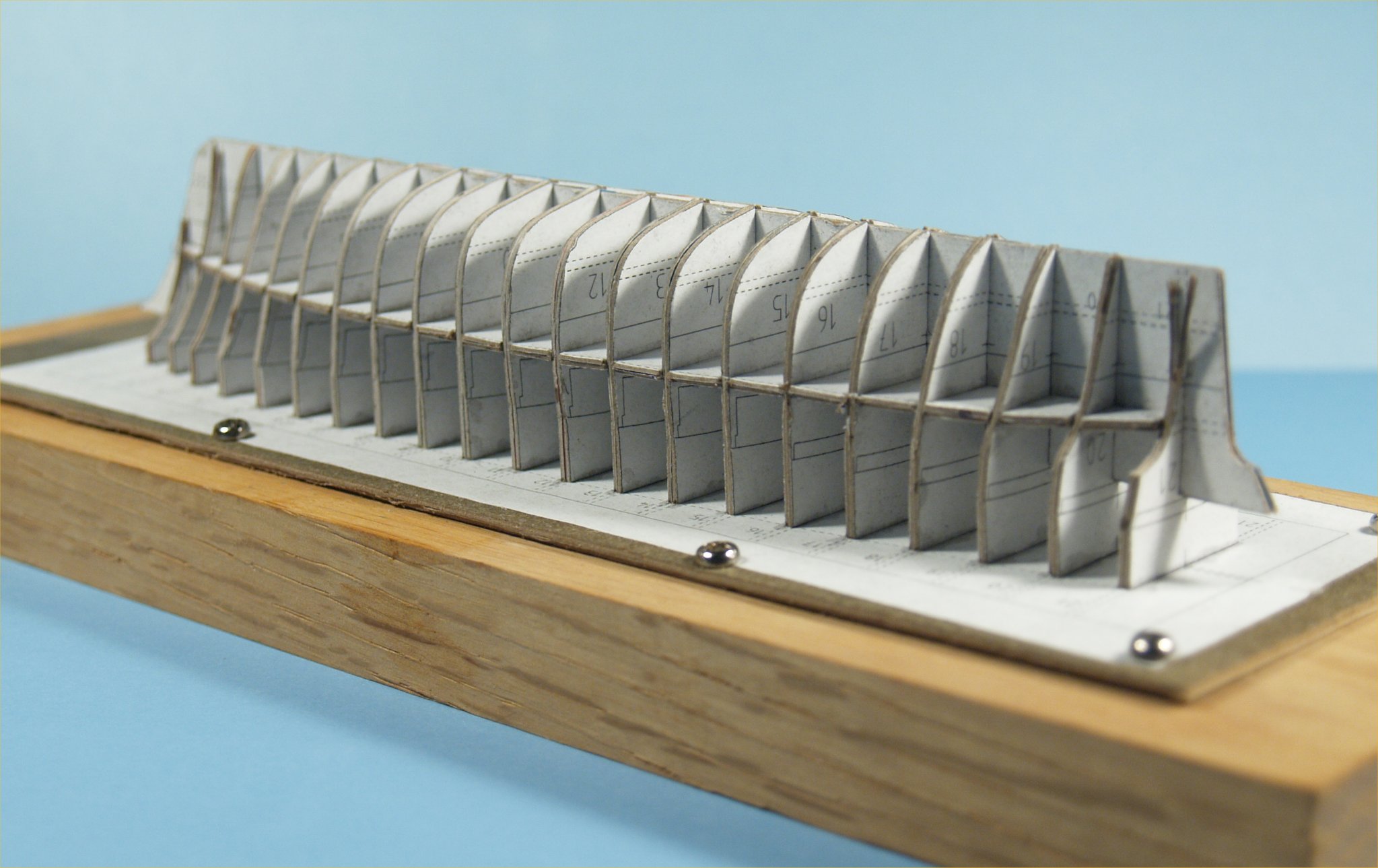
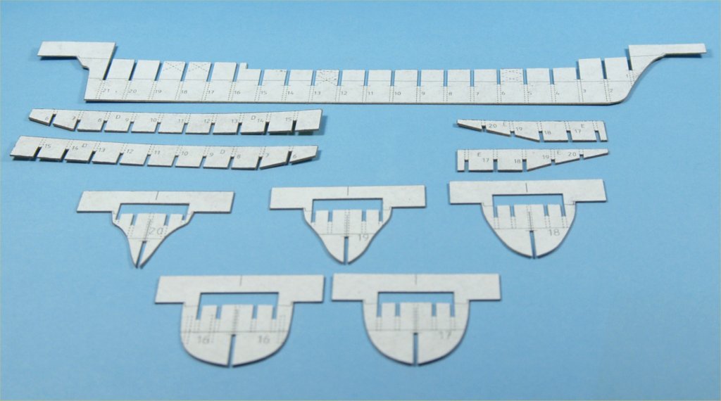
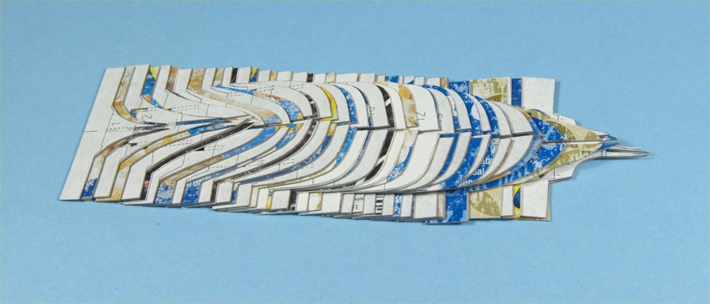
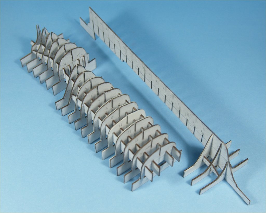
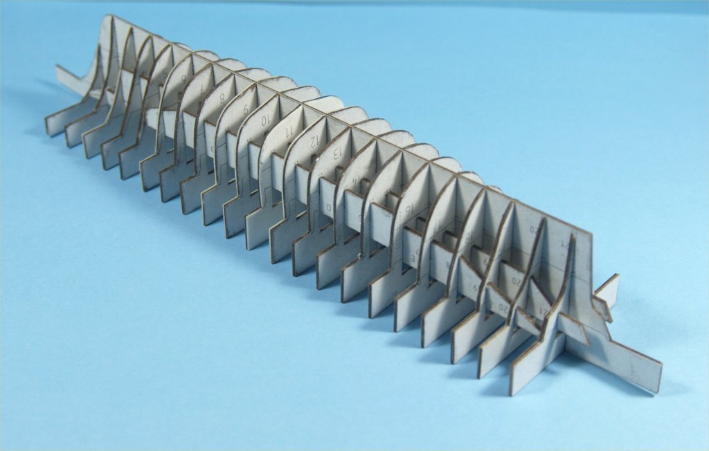
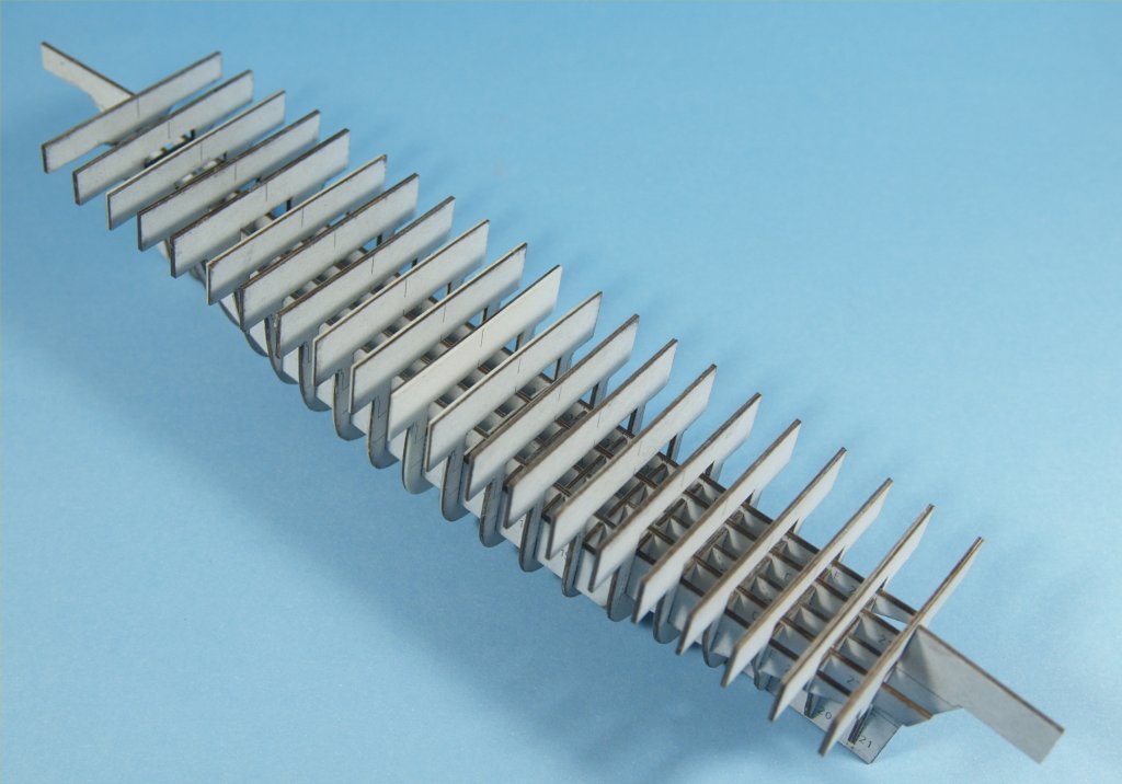
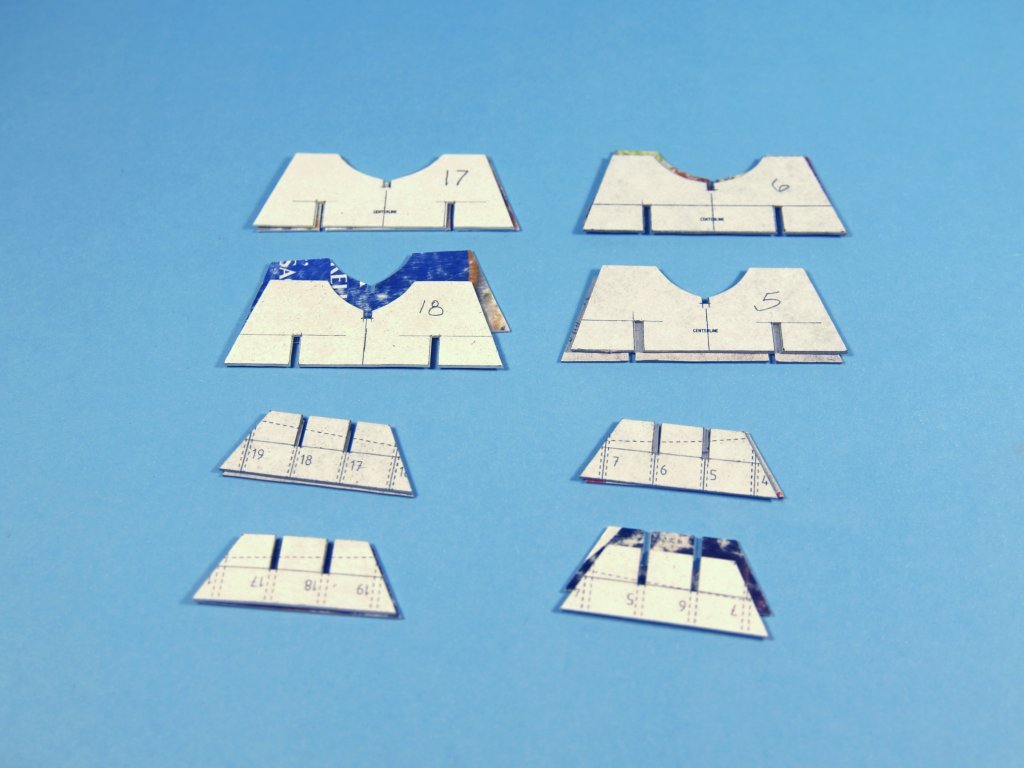
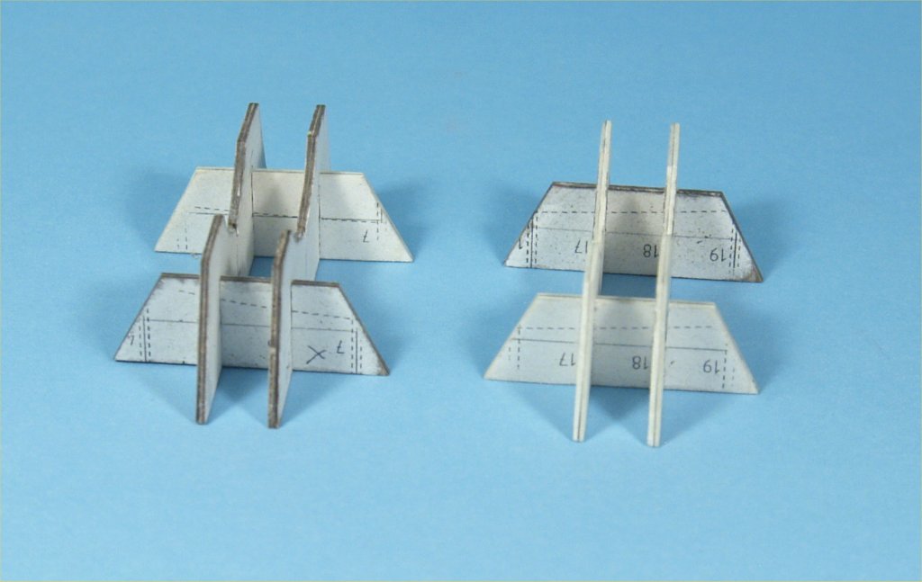
Before continuing with this build article I would like to review some of what I've learned, and how it affects the work as it progresses. First of all I have learned that I need to soak/saturate the card stock from packaging much better. Originally I only used multiple painted coats of thinned poly varnish to do this work. I was only saturating the uncolored side, which is in effect sealed off by the printing. I have since learned to sand the colored side of the card stock, using 320 grit sandpaper and a small wood block, to roughen up the surface and remove as much of the sealed surface as possible. The second thing I've learned is to use a small plastic tray, in my case the base of a plastic container used locally to hold bakery goods, to literally soak the stock for at least five minutes. This worked much better at hardening and saturating the card stock. It makes it slightly more difficult to cut out parts, but keeps the fraying from unsaturated inner parts of the stock down to a minimum. Although not evident from the photos shown thus far, the hull does have some places where the top of the bulwarks are not symmetrical side-to-side. One side has a slight bulge and the other a bit too much tumblehome inwards. I believe this is due to the fact that I did not cut the slots for the individual pieces well enough, in some places the bulkheads were not perfectly 90 degrees from the keel piece. I didn't realize the problems this would cause later. I figured that although the center keel piece was forced out of alignment at the deck level, once the tops of the bulkhead pieces were glued to the spacer piece it would straighten out. I was wrong, the top of the center keel piece was pushed sideways slightly in places, but I could not see this until the hull was planked and cut from the spacer piece so I could view that area. As a lot of the work involved soaking or gluing, and then waiting for up to 24 hours to continue work, I decided to see if I could improve on the hull by starting over completely. Remember, this whole things is an experiment to see what is possible and what can go wrong and how to improve things with card/paper modeling. I am still working with the original hull, as experimenting with it will help improve things overall. I redesigned the bulkheads and added some additional pieces to make what I believe will be a stronger and better hull. The following images show this new design. Like the previous plan drawings my CAD program exports rather poor images, I have all these drawings as PDF drawings if anyone is interested. The major changes to these plans are the additional longitudinal stiffeners and the open areas on most bulkheads at deck level. I am hoping that it makes cutting down to deck level much easier and more accurate. I also extended the bulkheads on each side right at the top of the bulwarks line, to make planking in that area much more accurate. I did make up the parts for the new hull, using the above mentioned soaking technique to the card stock this time. While the results were much better overall, it was a bit more difficult to cut the thoroughly saturated stock not to mention a lot more slot cuts were needed. The following images show some of the work on cutting out and gluing together that different parts. Each was made twice, and then each pair glued together to make up the final pieces. After the pieces were glued together to make up the hull parts, I dry fit each piece to all the pieces it would interact with in the final hull form. I made sure each piece fit easily and the pieces remained square to each other. It took a lot of time, and if a piece fit tight enough but slightly off square I would slightly enlarge the slot so that it would be square. Slightly over sized slots turned out not to be a problem, as there are so many pieces that fit together it did straighten it all out. The installation of the longitudinal pieces did require them to be installed on all the bulkheads that they interacted with at one time. And, due to the limited open areas above the deck level, they had to be put in place at 90 degrees to their final position. They were then slid into place and rotated to fit into their respective slots. A bit fiddly to do, but it worked out quite well due to the dry fitting and trimming of all the slots. The hull parts were put together in sub-assemblies, which were then added to the center keel piece. The larger center section had to be added first, then the stern and bow areas added. The following photos show this work. All the joints were then glued with white glue. This hull form was very stable. This time I glued the spacer print directly to a 3/8" maple board, and glued the tops of the bulkheads to that. Unlike the first hull, this time all the bulkheads lined up perfectly on the spacer print, with no adjustments needed. The following photo shows the final results of this process. Anchor's A Weigh! John Fox III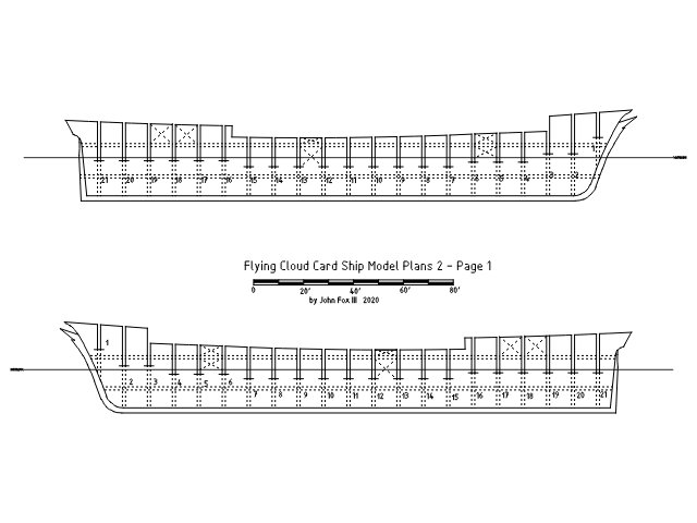
-
Experiments in Card/Paper Modeling
John Fox III replied to John Fox III's topic in Card and Paper Models
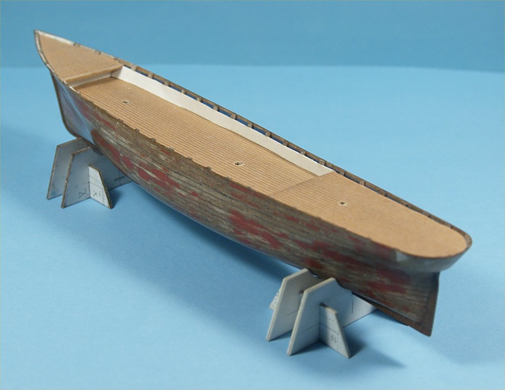
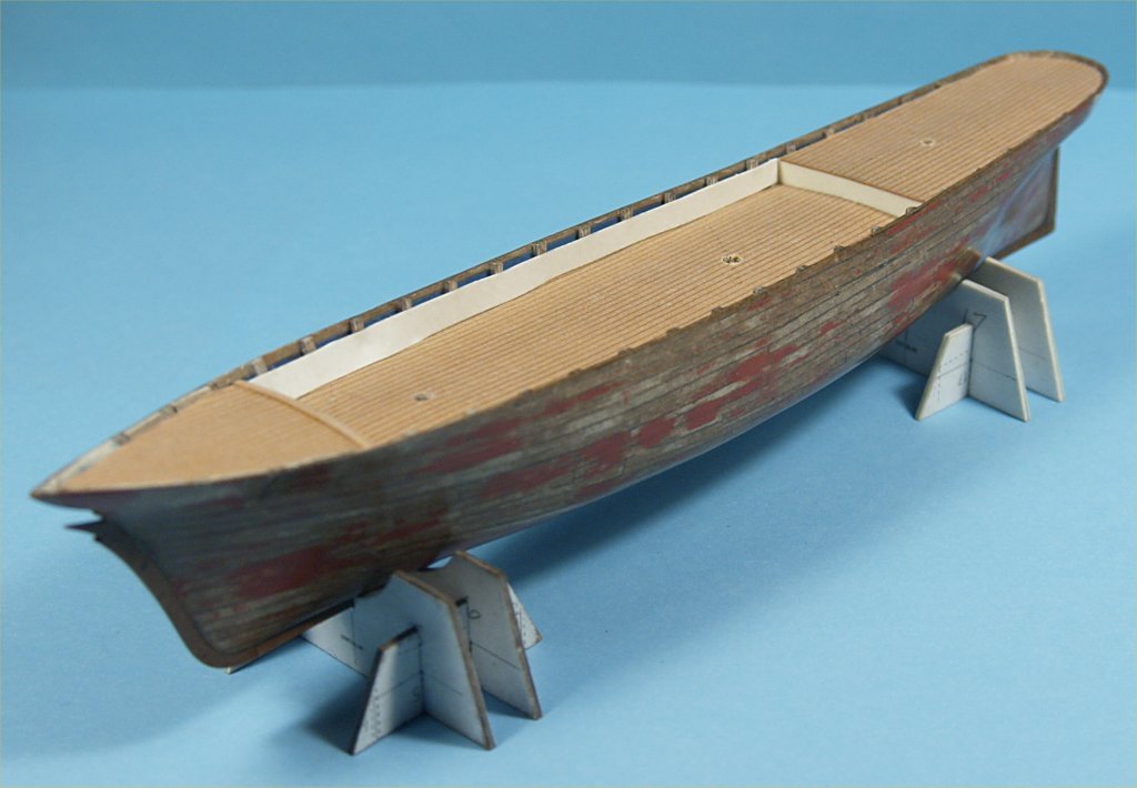
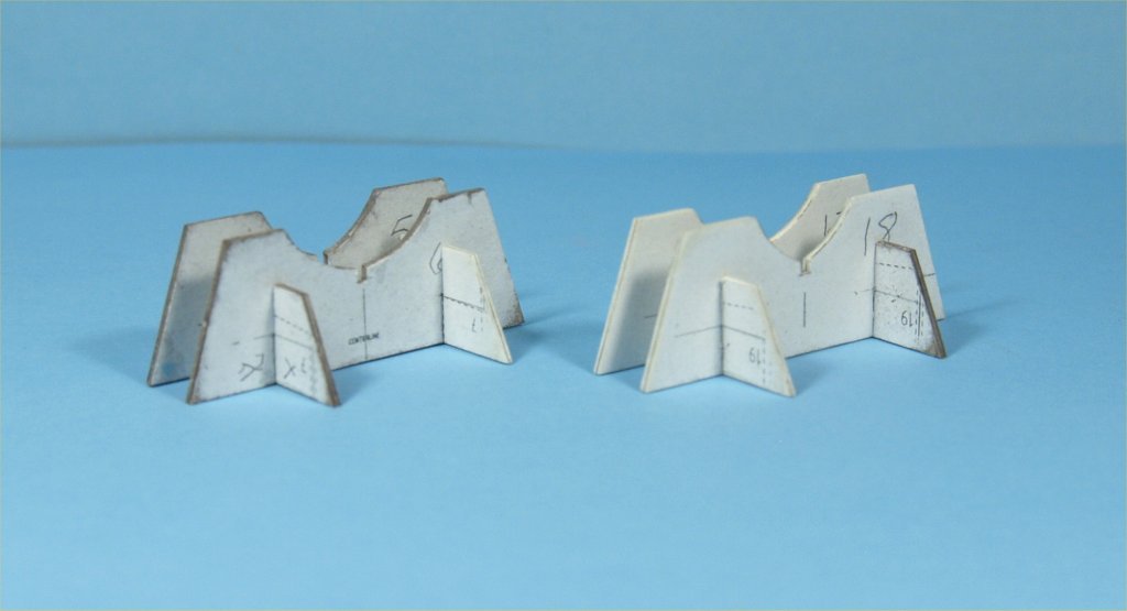
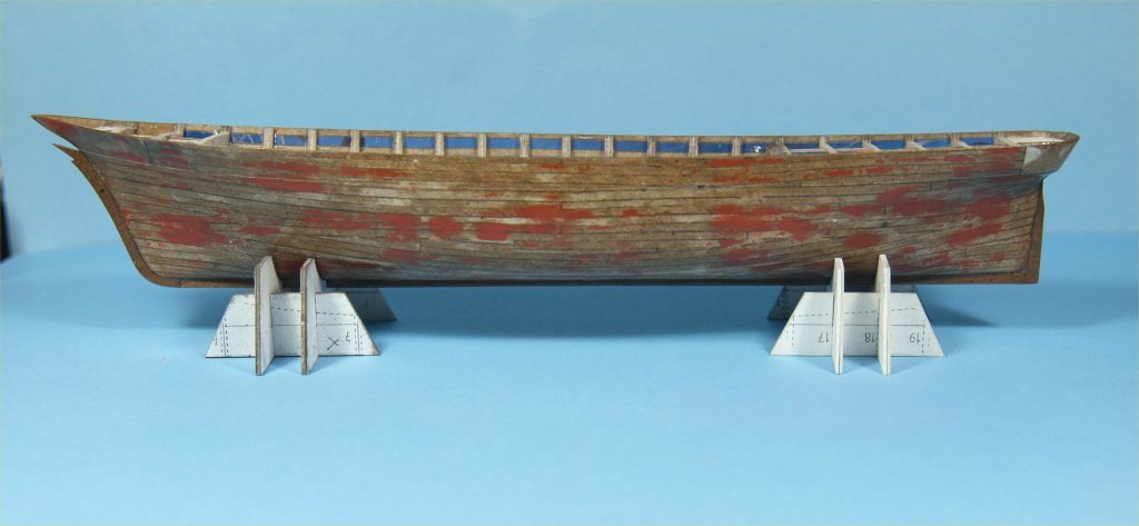
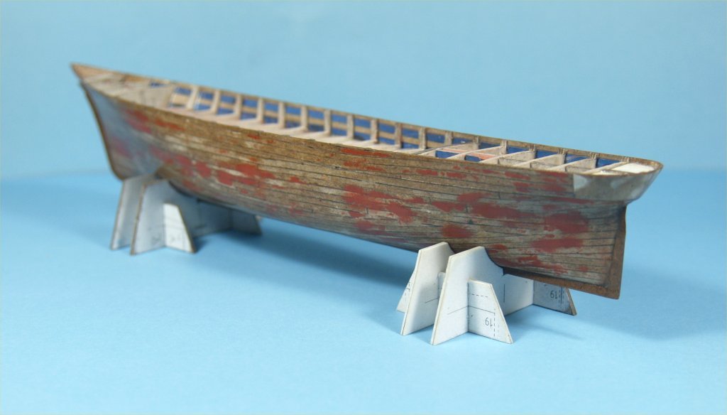
Greetings All, The work on the card and paper clipper model continued with quite a few more sealing and sanding, with small amounts of Bondo. Once I had a decent hull I made up the keel, stem and stern posts out of multiple layers of board. After reading more online about card models I learned to saturate the card stock with thinned down poly varnish, in order to make it stiffer and less prone to fraying when sanding. It also made cutting a wee bit harder, but worth the effort as it shapes up nicer when saturated. I did this by using a large art paint brush and applying the thinned varnish, then letting the card stock dry, and repeating the process until no more varnish would soak into the stock. The keel and stern/stem posts were made from this saturated card stock. I then used epoxy glue to install these parts. Unfortunately, I had to use painters tape to hold the parts in place while the epoxy cured, this resulted in removing the sealed surface of the hull where the tape was attached. It left fuzzy areas, so more sealing and light sanding was necessary to seal the entire surface of the hull again. At this point I used extra prints of four of the bulkheads and the spacer used to glue the bulkhead tops to the board to design and cut out card stock pieces to make up a couple of stands for the hull. The following photos show the results of this work. More to follow as work progresses. Anchor's A Weigh! John Fox III
-
Experiments in Card/Paper Modeling
John Fox III replied to John Fox III's topic in Card and Paper Models
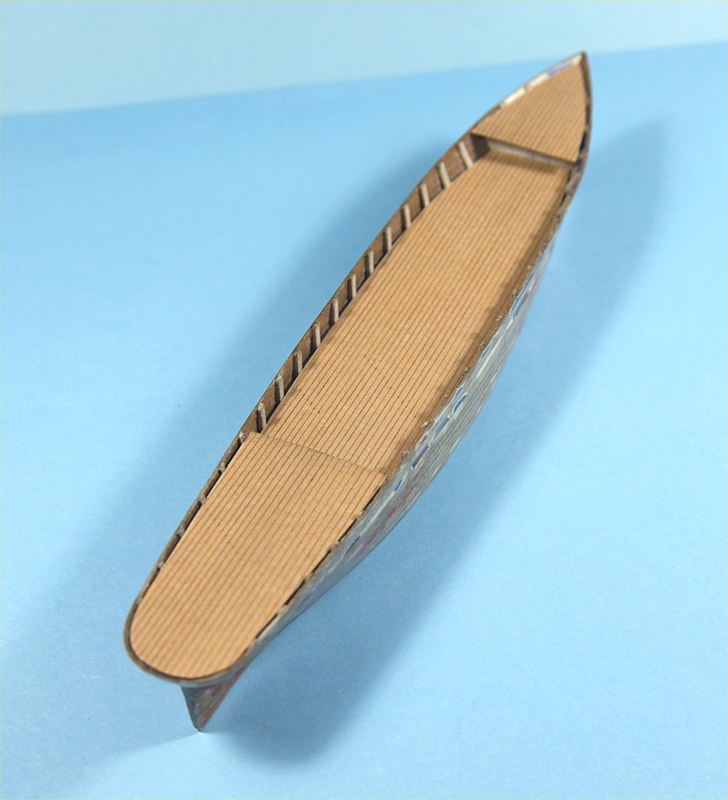
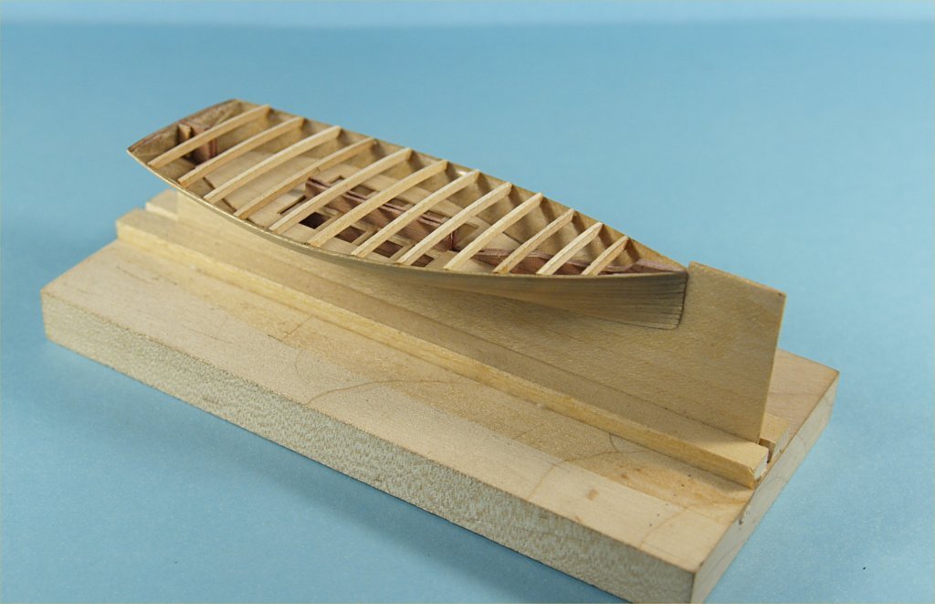
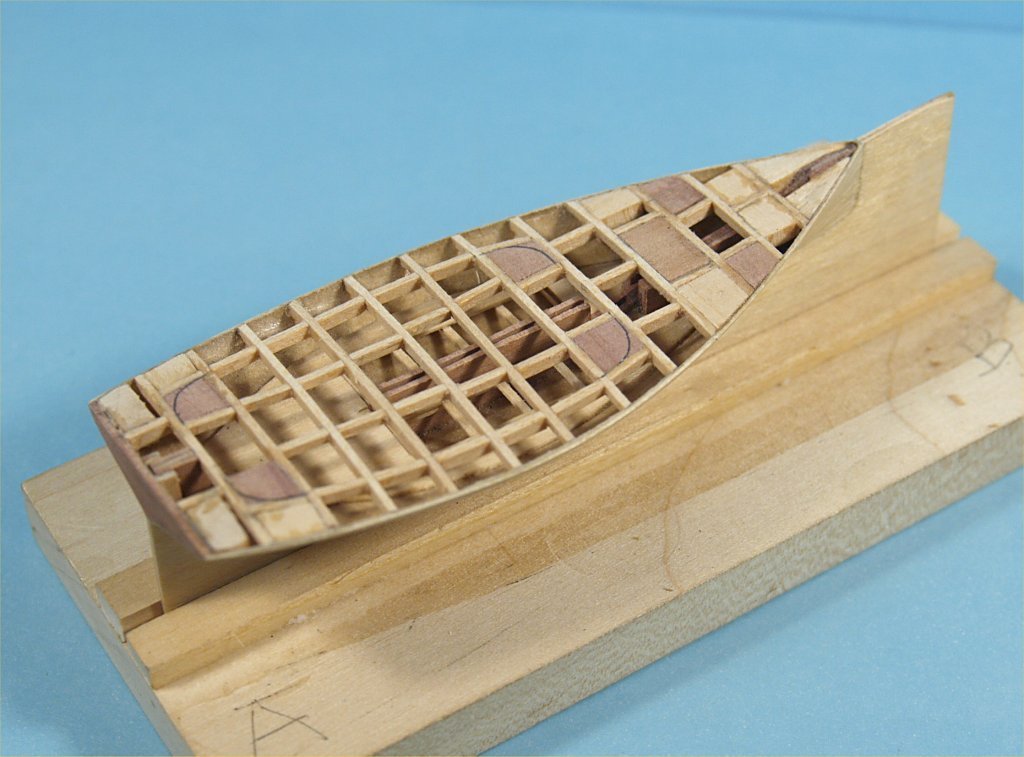
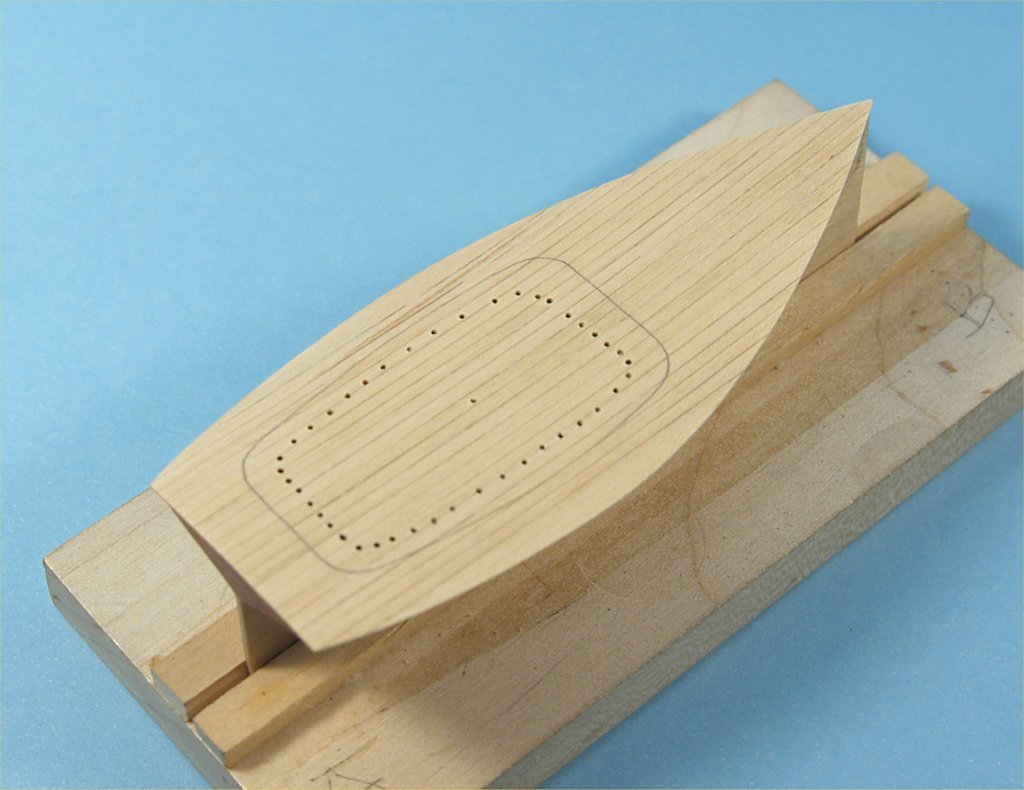
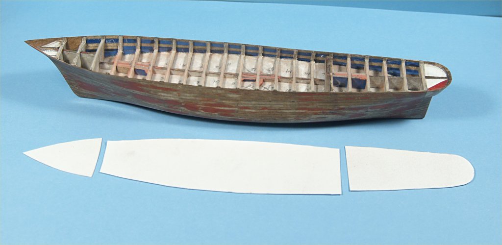
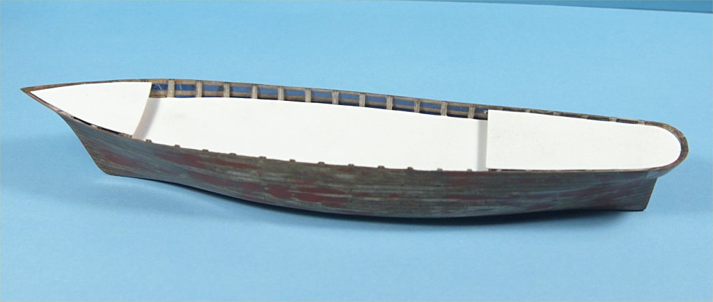
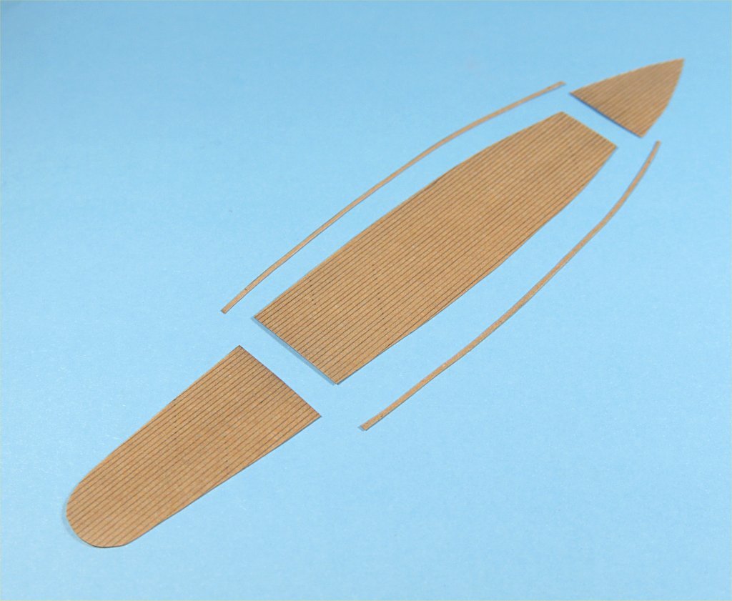
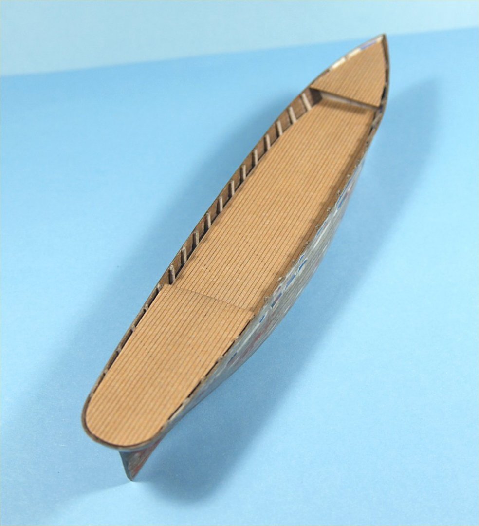
The work on the hull progressed by sanding down all the planking, to get as smooth and fair a surface as I could. I sanded, then applied poly varnish thinned 50/50 with paint thinner until it no longer soaked in. Waited for the varnish to dry, then sanded again. I repeated this process many times. While sanding I could see areas where the planks pushed inwards slightly, and small gaps in the finish. I used Bondo glazing and spot putty, applied with a stiff piece of styrene plastic, to cover the gaps and low spots. Again, after Bondo dried the hull was sealed and sanded. I did this perhaps 3 or 4 times before I had a smooth surface over the entire outer hull shape. Once I had a decent hull shape I used a razor saw to cut through the bulkhead extensions that held the hull to the cardboard mounted on the maple board. The following photos show the hull to this point. Work on this first hull progressed with carving the insides of the bulkheads down to the deck levels. I used a chisel type blade in my knife to do this work. The raised forecastle and quarter decks were reasonably easy to work, while the lower mid deck was difficult. I did add some extra pieces of cardboard to the center keel piece in the locations that would later have holes drilled to accept the mast extensions. All the deck areas were then sanded down to the deck lines on the bulkheads, a small amount of Bondo was added as the extra pieces did not quite come flush with the deck level. The following photos show the work thus far. I next worked on making templates of all the deck areas. I used thin paper cut to approximately the right size and shape at first, then pressed them into locations and creased it sharply at each of the bulkhead extension inside the bulwarks. The paper was removed and cut to follow the crease curves. I traced these templates onto thinner card stock and tested the fit on each deck location to finalize the exact shape for each deck area. A piece of thinner cardboard was then soaked in a bath of maple stain, to saturate it completely and evenly with color. I had tried just brushing stain on the board first, but the colorization was too uneven. Lines were then drawn on the board, spaced 1/32" apart, and the thin board templates used to trace the shape of the decks onto the stained board. These were cut out and tested to fit in their places, but not glued down yet. I also traced the outside edges of the main, lower, deck onto a non-lined area of the stained board and cut waterways for the hull. Following photos show some of this work. More to follow as I work along. Anchors A Weigh! John Fox III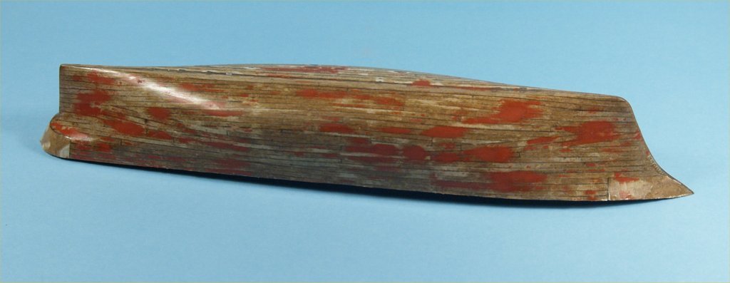
- 28 replies
-
- 12
-
-
Experiments in Card/Paper Modeling
John Fox III replied to John Fox III's topic in Card and Paper Models
I actually gave thought to doing something between the bulkheads, but silly as it may be, this being my first experiment with card/paper ship modeling, I am planning on using nothing but paper and cardboard. My only foray beyond this is a very small amount of Bondo used to fill in some small places to bring the hull to fair. The hull only being a bit over 8" in length, I plan on painting and not planking any further. Future postings will show this a bit more, as well as my attempts to make paper masts by forming tubes over various diameters of rods of differing materials. -
Experiments in Card/Paper Modeling
John Fox III replied to John Fox III's topic in Card and Paper Models
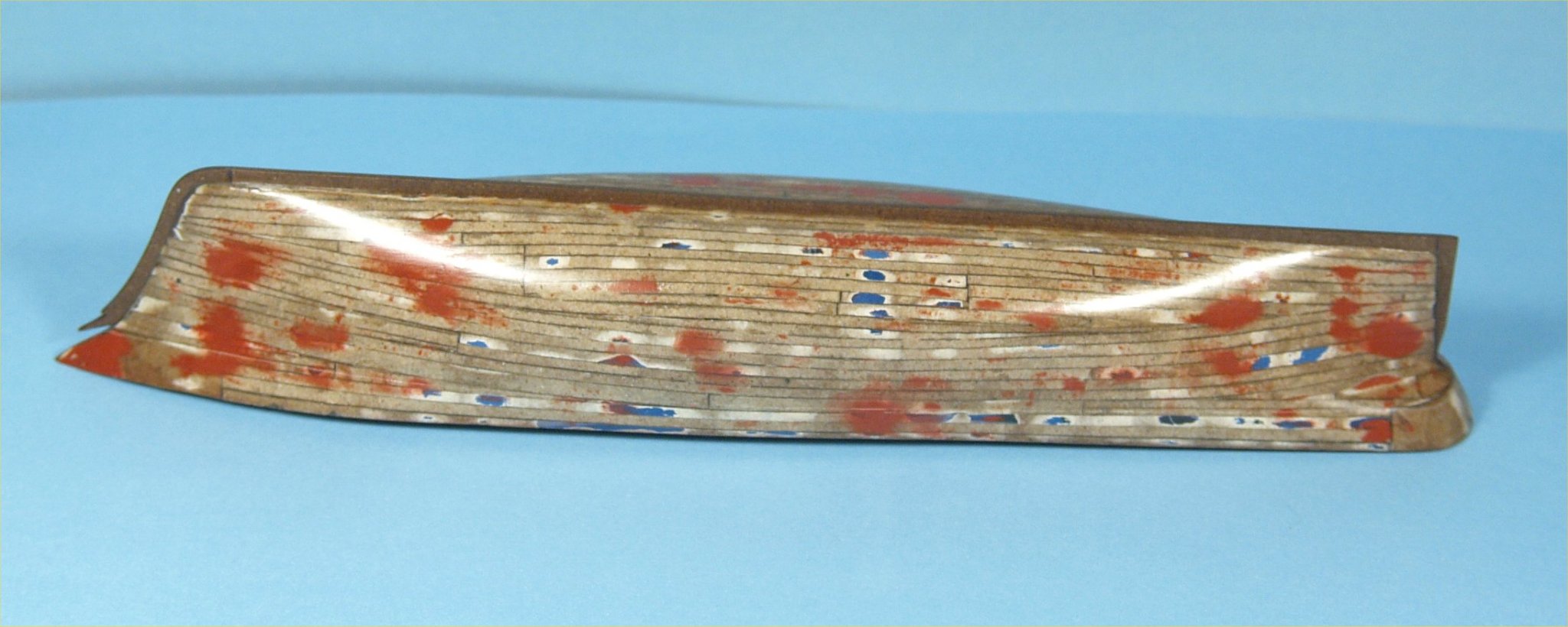
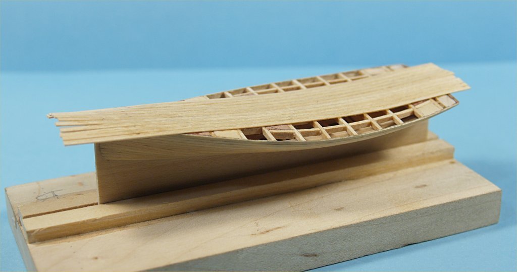
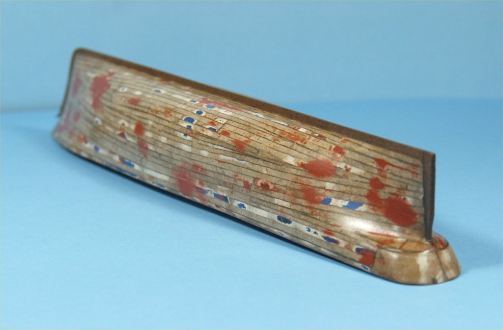
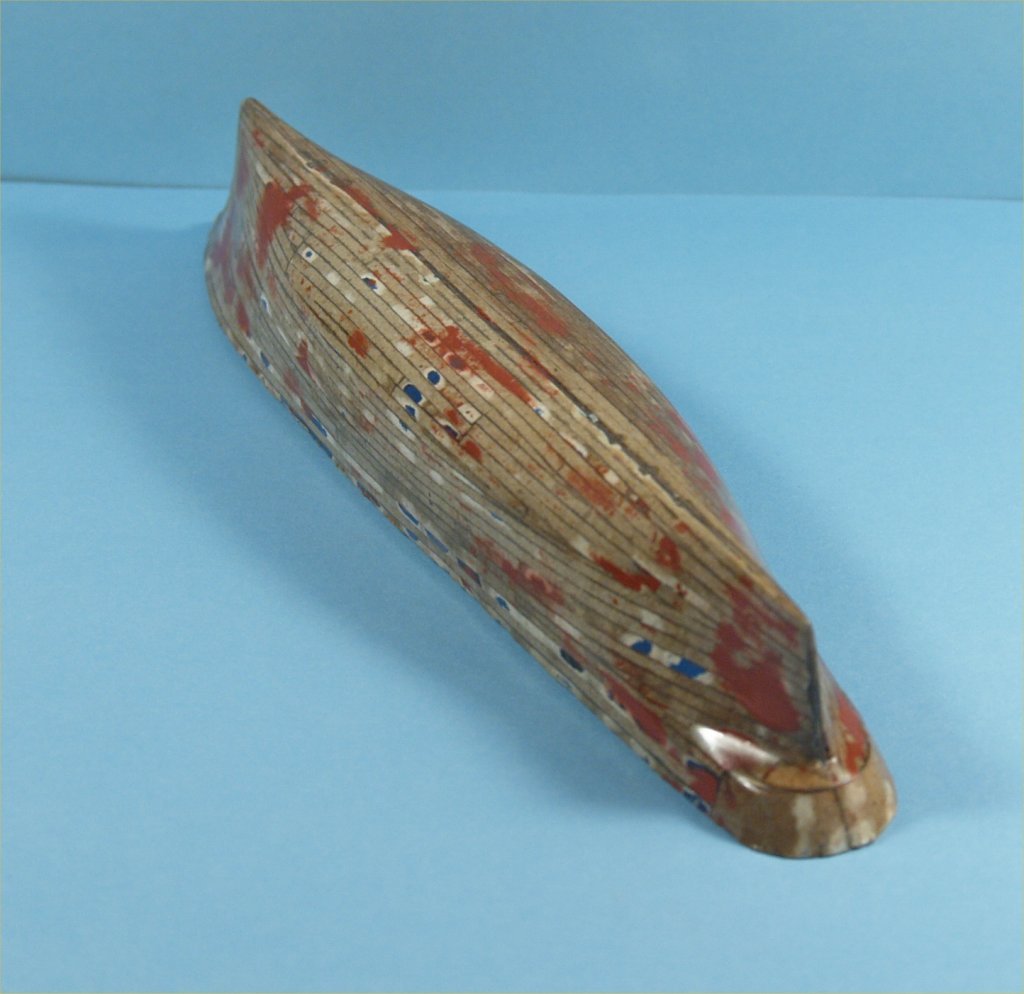
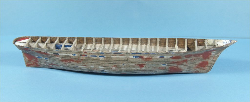
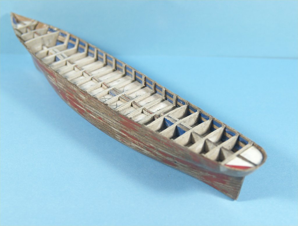
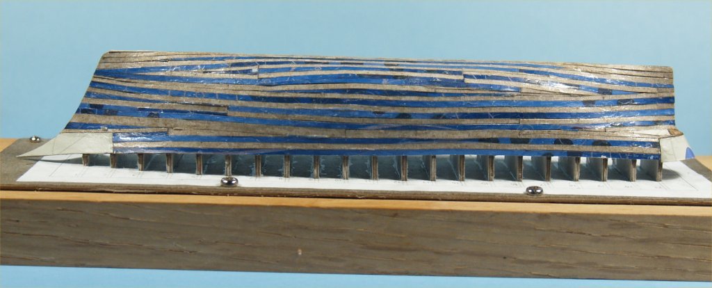
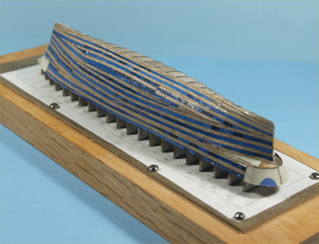
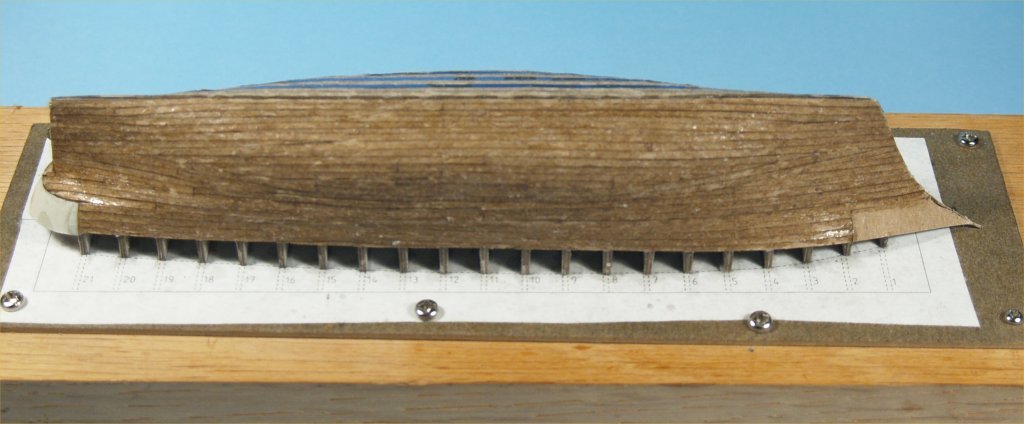
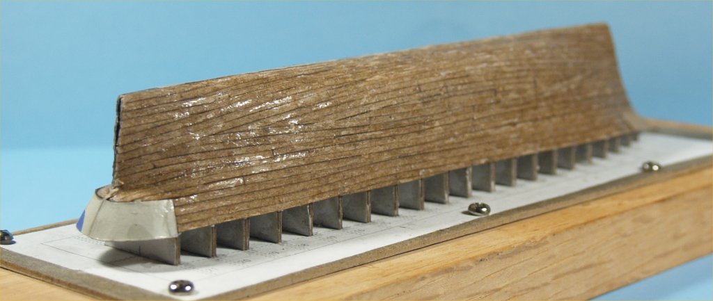
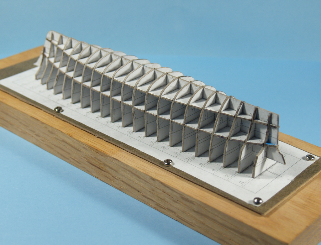
Continuing with the card/paper model of Flying Cloud. The next step was to fill in between bulkheads and keel at the bow and stern with layers of board cut to fit as I added them. Photos below shows the results after cutting and shaping them a bit, and applying CA glue to harden them. I also started sanding the bulkheads edges to fair in the hull shape. What I found was that in many places the weaker inner parts of the board would splay the outer harder parts outward as I sanded. I continued sanding and fairing the hull, had to apply CA glue between each sanding session. It took quite a few sessions to get the hull as fair as I could. I then cut 1/16" wide strips from the board stock to use as planks. I found that as carefully as I could, using an X-acto knife and #11 blade, the cut edges were not perfectly vertical. I used this slight angle to close gaps while planking. To do this I alternated using the printed and non-printed sides of the strips on the outside. At the bow and stern I used larger pieces of board to make it easier to plank above the deck line. The following photos show the first side planked. I did not use a traditional planking style, I started at the keel, the waterline and the top of the bulwarks and worked my way with as long a strips as I could. Then filled in with individually cut pieces to fit. One thing I learned was that this cardboard was not very stiff, had to be careful when holding the plank to a bulkhead edge, as it tended to push the board inward slightly between bulkheads. I used CA glued applied with a needle to attach each plank. I then coated the entire outside of the planking with CA glue to harden it. For the second side I decided to use a different cardboard stock, one without the colored/printed side at all. I planked it in exactly the same way as the first side. Not sure why I did this, except the stripped first side sort of looked odd to me. Following photos show progress to this point.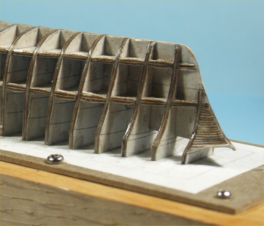
-
Experiments in Card/Paper Modeling
John Fox III replied to John Fox III's topic in Card and Paper Models
I really had no idea where to post my log. There most definitely is more, I have it all saved in a .doc file I keep as I work along, but only the text transferred when I tried to copy it and paste it here. I had to crop and resize each photo again to post them. I have no idea how to move the posting. -
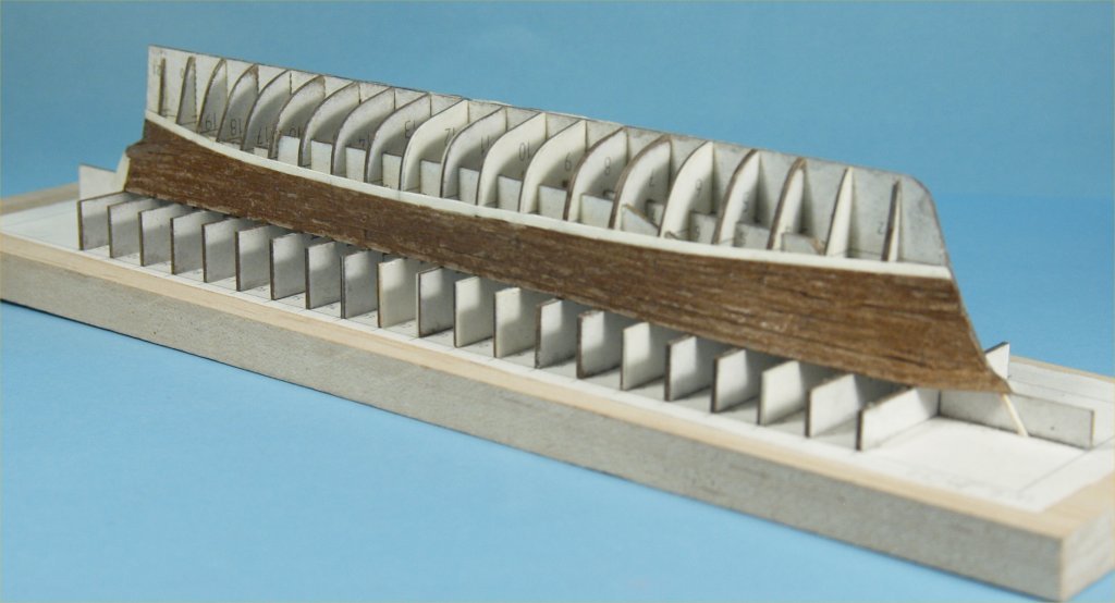
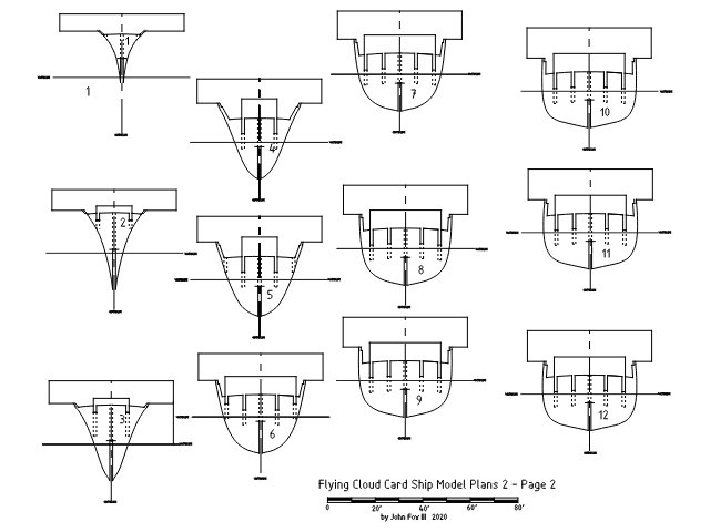
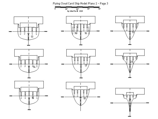
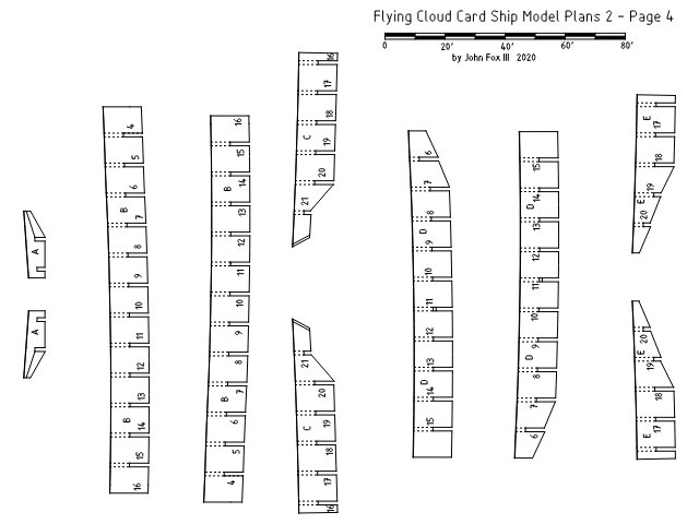
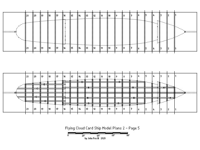
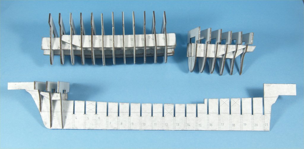
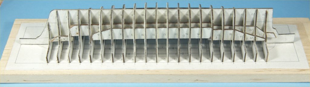
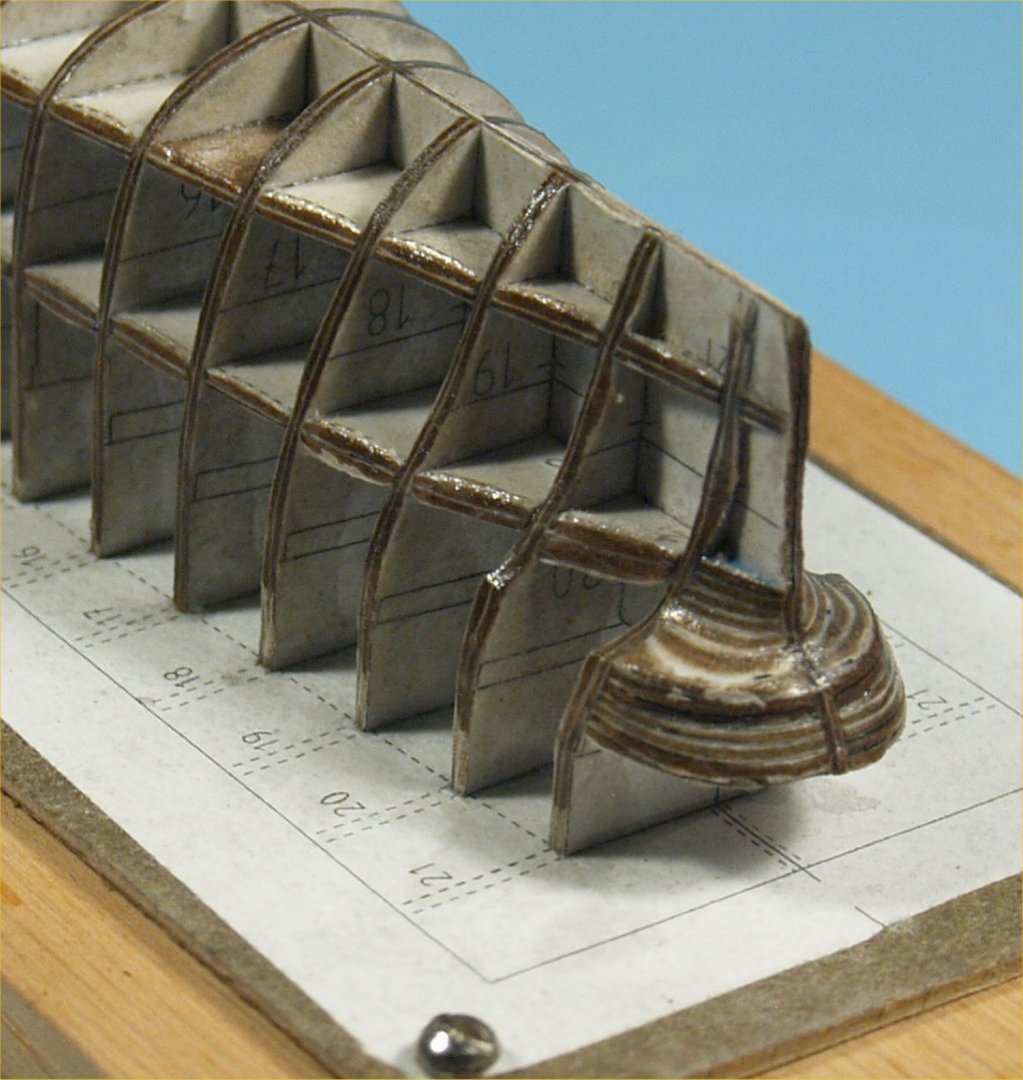
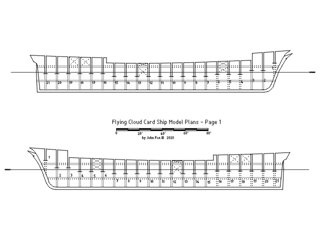
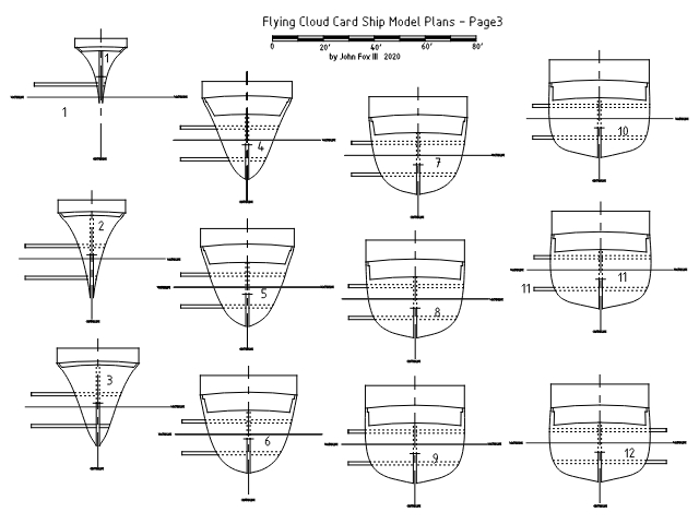
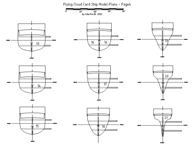
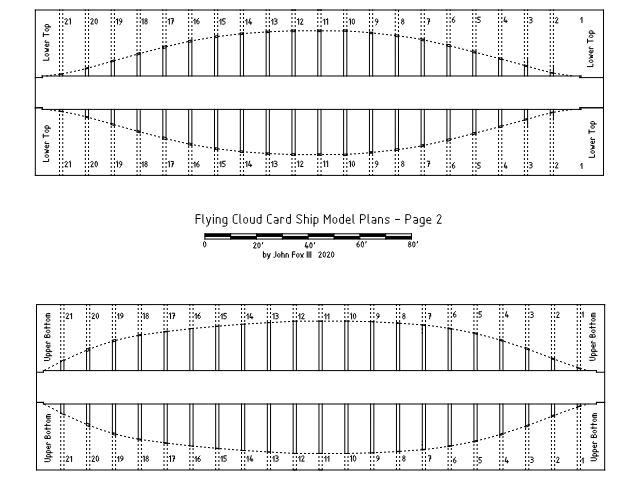
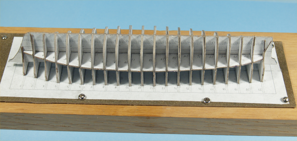
I've been intrigued lately when viewing build logs on the NRG web site, among other places. Decided I would give it a try and see how it all works. I started by viewing the vast number of CAD ship plans I've developed over 40 years of modeling sailing vessels. I was interested in something fairly simply, but one I had enough information already drawn up in plans. I ended up settling on the clipper Flying Cloud. I drew up the plans 27 years ago for a ship in bottle model at 1:750 scale. For a card/paper model I decided on a scale of 1:350, making the hull slightly over 8" long. I spent a little time taking the original plans and adapting to a bulkhead type of model. My original was a carved solid hull. The following images show my drawings for a card/paper model. The .jpeg images were exported from QCAD, as exports the line weights are too heavy. I have the same images as PDF images if anyone is interested. The solid lines are cut lines, the dotted lines are where parts get glued on. The "X"'s are areas that have added thickness, to make a solid area for the masts. The waterline is not a cut line. The rectangles outside the hull lines designate where spacer pieces would lay. The following drawings show the spacer pieces. These were drawn before I actually thought it all out. In the end, though designed to be single pieces that slide into the gaps between the bulkheads on the horizontal dotted lines, that would make it too difficult to glue and cutting it off later. I ended up simply cutting individual pieces and gluing them in place. The photos above show the hull after the first layer of spacer pieces were glued in. You can see a few places on the first photo where the doubled bulkheads spread apart slightly due to being squeezed where they fit onto the keel piece. The photo above shows the hull with the second spacer pieces glued in place. I made to cut these so that the bulkheads were pushed together. I then applied CA glue to all the joints between pieces and covered all the edges. More to follow.


- 28 replies
-
- 12
-