
John Fox III
-
Posts
119 -
Joined
-
Last visited
Content Type
Profiles
Forums
Gallery
Events
Everything posted by John Fox III
-
 Thank you! I do try! <Grin> Been doing this kind if miniature work for 40 years, good to know I did learn something in all that time! <G> Anchor's A Weigh! John Fox III
 -
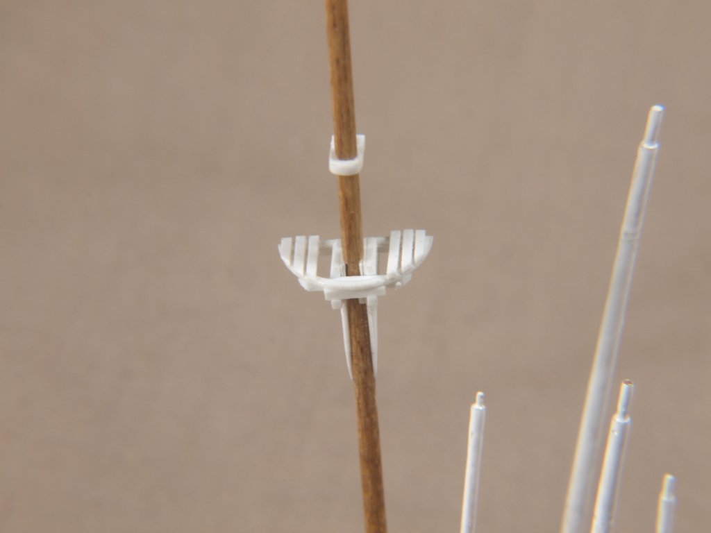
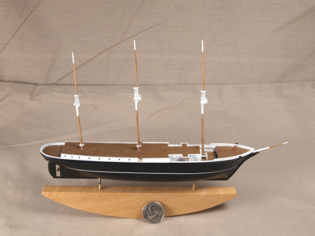
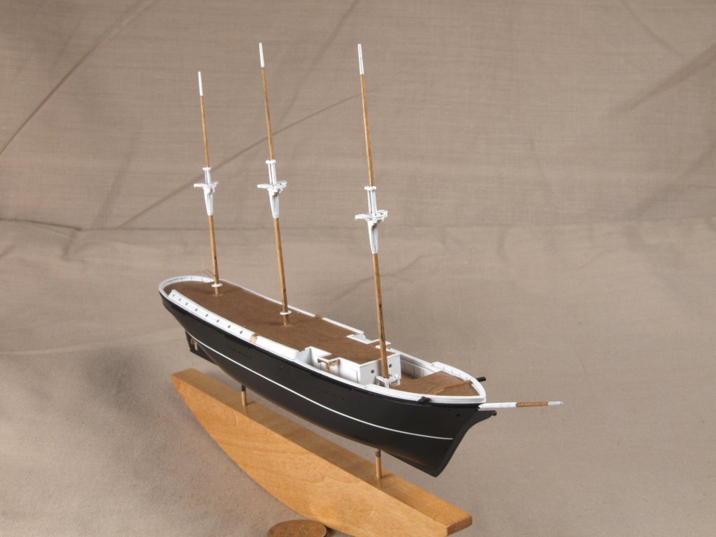
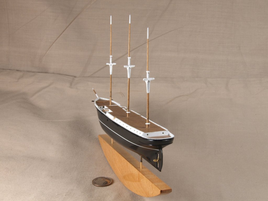
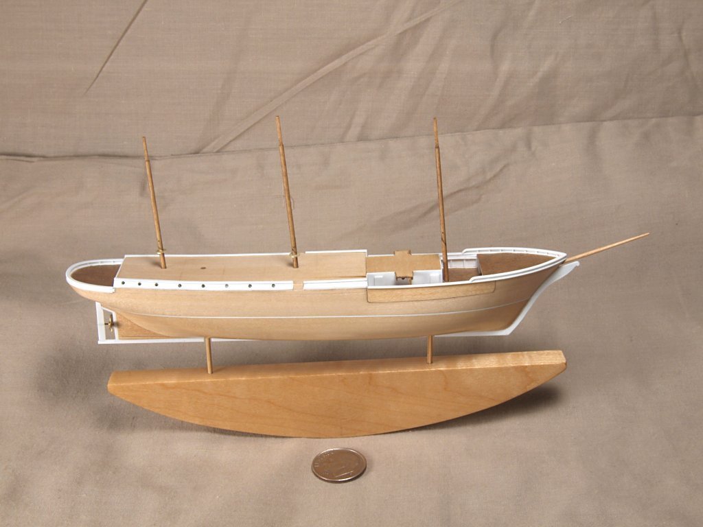
Greetings All, First a few shots of additions to the hull of my Endurance model. Added masts, temporarily, plus waterways on upper deck. The fore pin rail is brass, painted white. I used brass for pin rails as at this scale wood often splits, plus the additional strength come in handy when one has to tension the rigging lines from outside the light bulb after insertion. Additional styrene plastic trim pieces and maple veneer chain plates. Next I have the finished yards and masts, with styrene plastic tops, cap, etc.. And finally today the air brushed hull. The propeller is brass, plus added the catheads. Anchor's A Weigh! John Fox III

- 60 replies
-
- 12
-

-
Thanks! I do try! <Grin> BTW, bet one of the moderators could provide a walker if you keep stumbling around! <Grin> Anchor's A Weigh! John Fox III
-
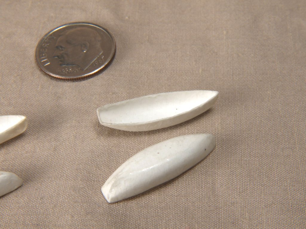
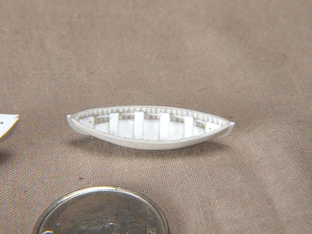
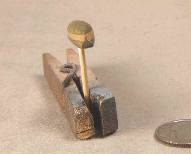
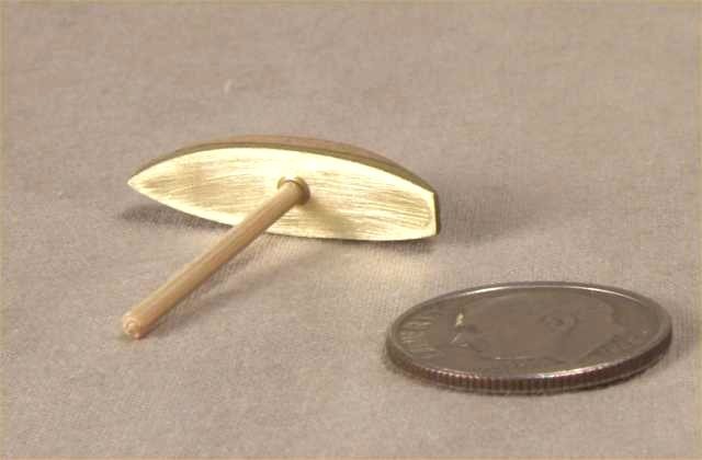
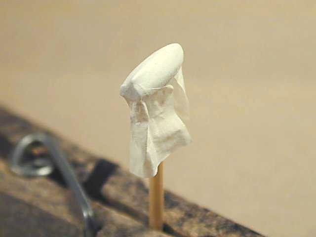
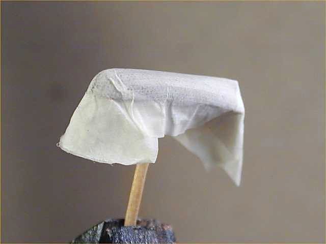
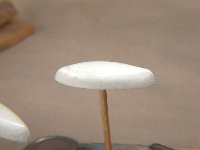
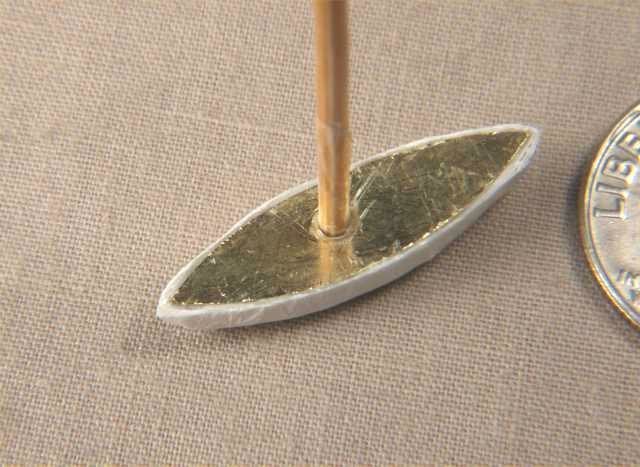
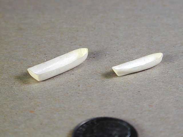
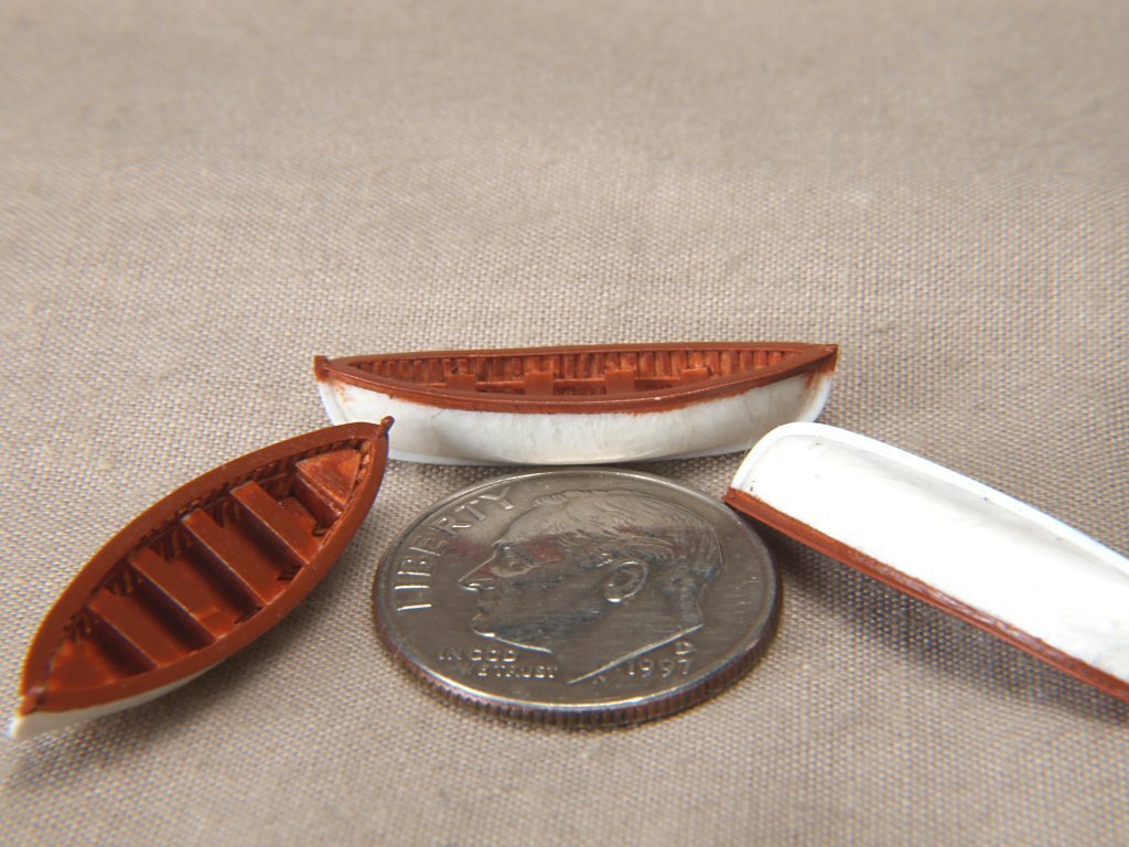
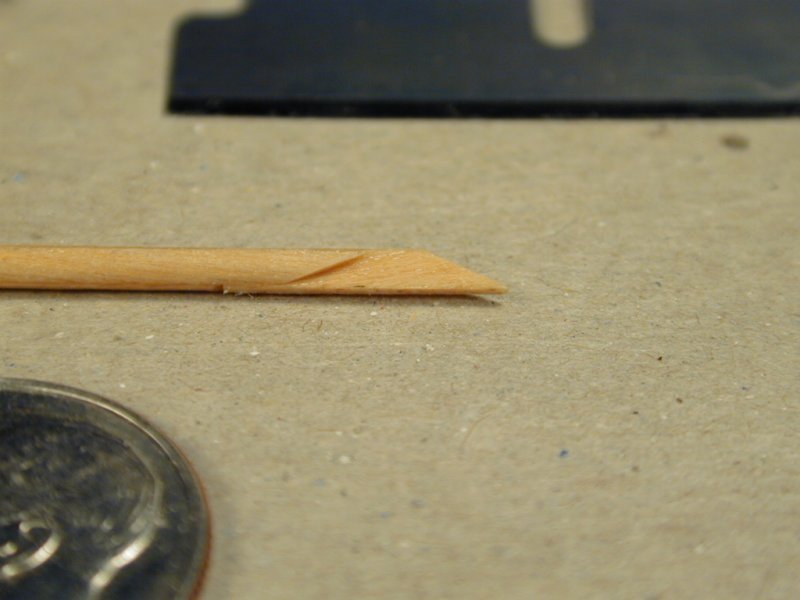
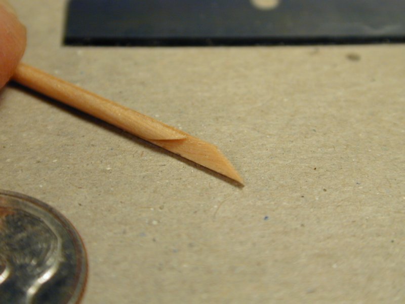
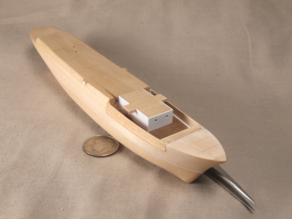
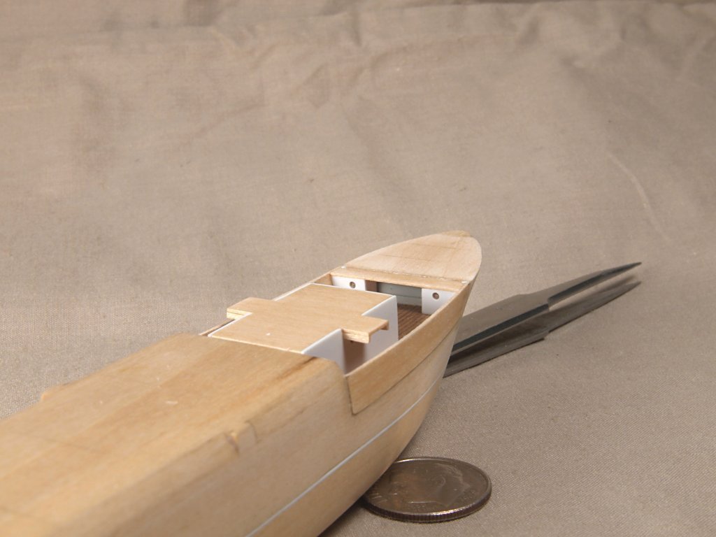
Greetings All, Thought I would add here the process used to make the ship's boats for my Endurance light bulb model. I use the same basic technique to regularly make these for my of my models, at different sizes and scales. The materials used are cigarette papers and thinned white glue, 50/50 mix. The basic process is t make a wooden plug of the interior hull shape, sealed multiple times, with a brass shim glued to the top surface, where the top of the bulwarks would be. The brass is used to keep the top edges of the wooden plug from being cut down as one cuts the paper to form the bulwarks top. A hole was drilled and a toothpick glued in to have a handle. The great thing about this method is one can make many copies of a boat, and have them all the same size and shape. To form the hulls, the cigarette paper is dipped into the thinned glue, excess glue scrapped off, the the paper is carefully draped over the plug. The paper is very delicate when saturated, so tears easily. A well sealed round toothpick is used to mold the paper tightly to the plug, doubling it over itself where necessary, usually at the bow and stern. Once the paper has dried, usually after 24 hours, the paper is carefully cut along the brass. Multiple layers of paper are used, depending the size/scale of a particular boat. When the paper is thick enough, trial and error are used to determine how many layers are needed for a given boat. Once the final layer is added, a thin coat of CA glue is applied over the outside of the hull, to harden it. At this point the hull can be "popped" off of the plug, usually use the tip of an X-acto blade to pry the hull at the top of the bulwarks to help get the hull free of the plug. Then the interior surface is also coated with CA glue. Finally the outside surface of the hull is sanded to remove the thickened areas at bow and stern, where the paper was overlapped to conform to the hull shape. The interior of the boats are then added. One method for adding framing was to cut a floor piece of sheet styrene plastic, then glue thin strips to the underside of this floor piece. The floor piece was then pressed down into the boat hull, while a fine wire was used to apply a tiny amount of CA glue to the strips, to hold them against the inside hull surface. Thwarts and other details are added, made from styrene or thin wood strips. Finally the keel, stem and stern posts were added, also of plastic strips, and the hulls painted to suit the model. Anchor's A Weigh! John Fox III
- 60 replies
-
- 15
-

-
-
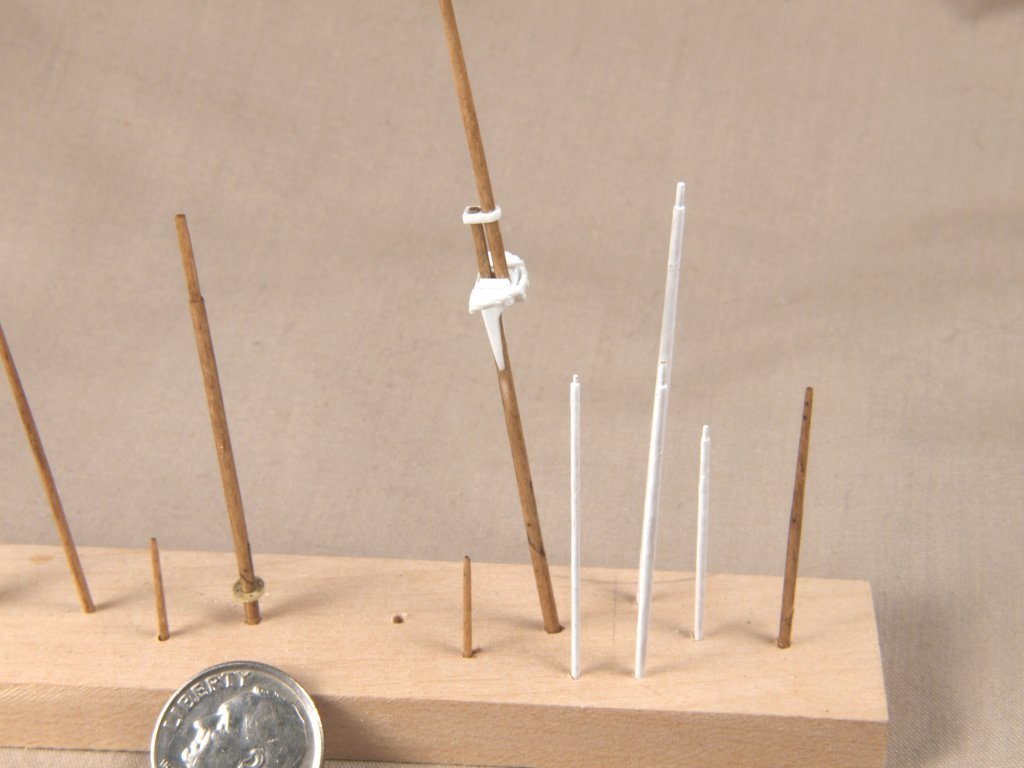
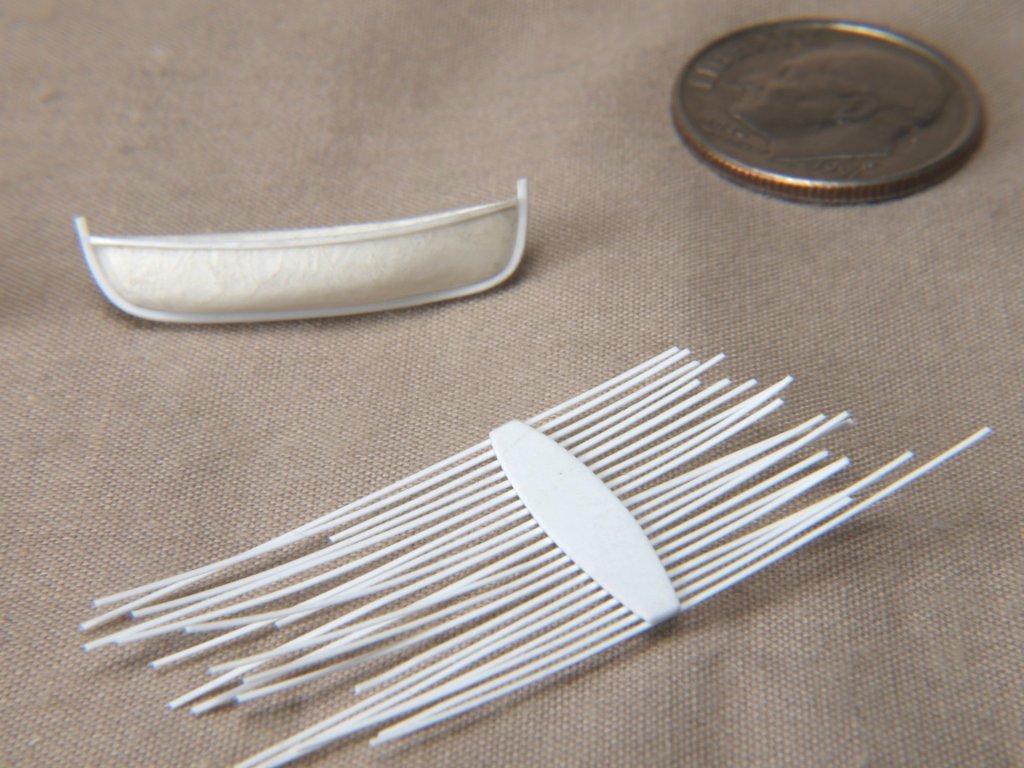
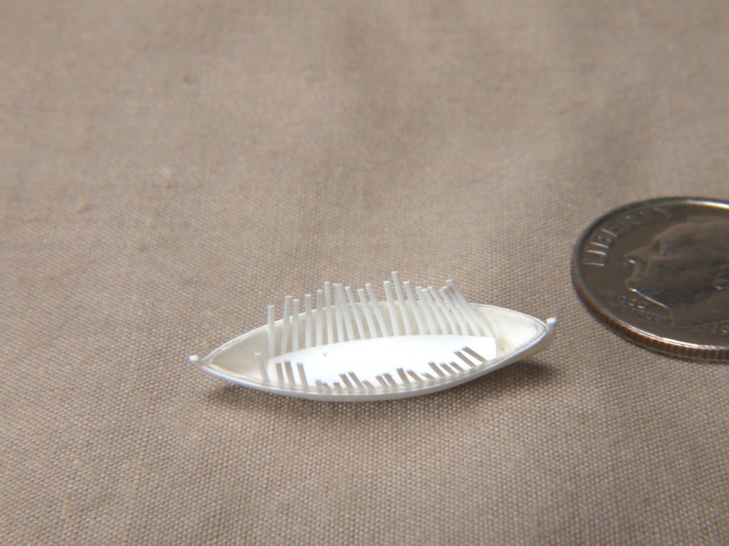
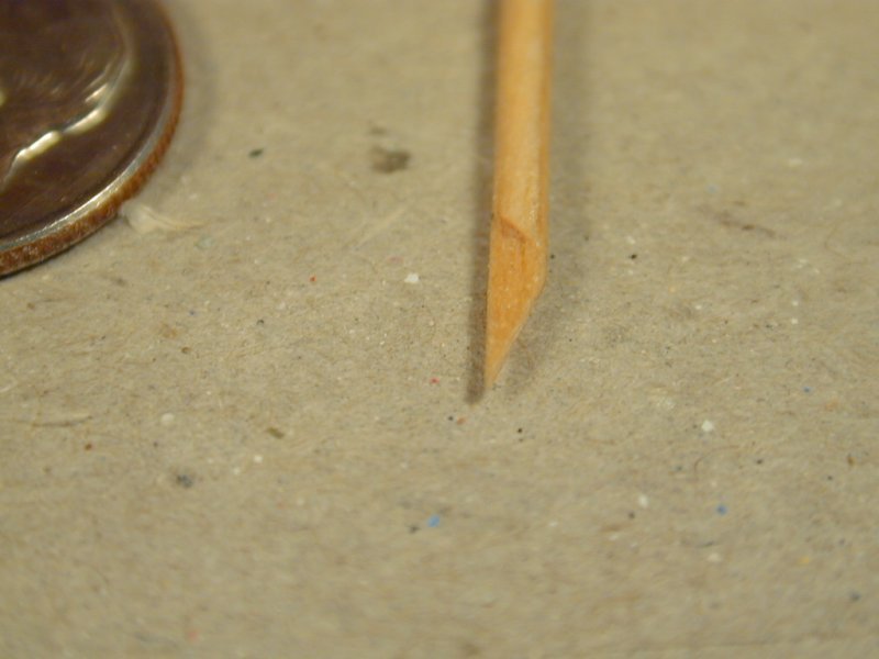
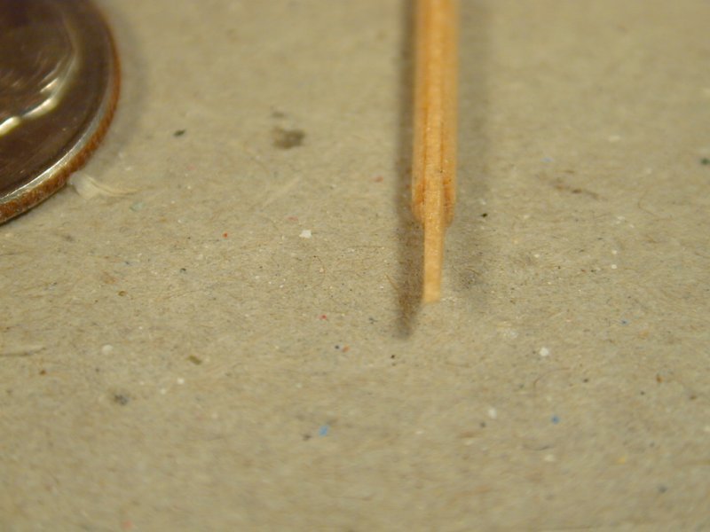
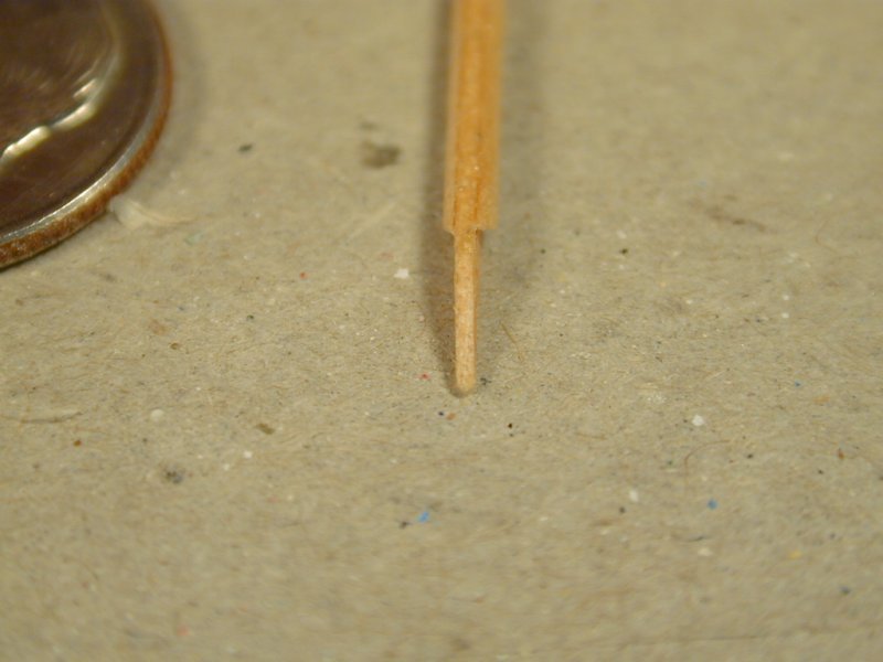
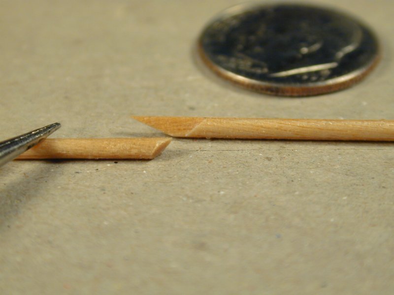
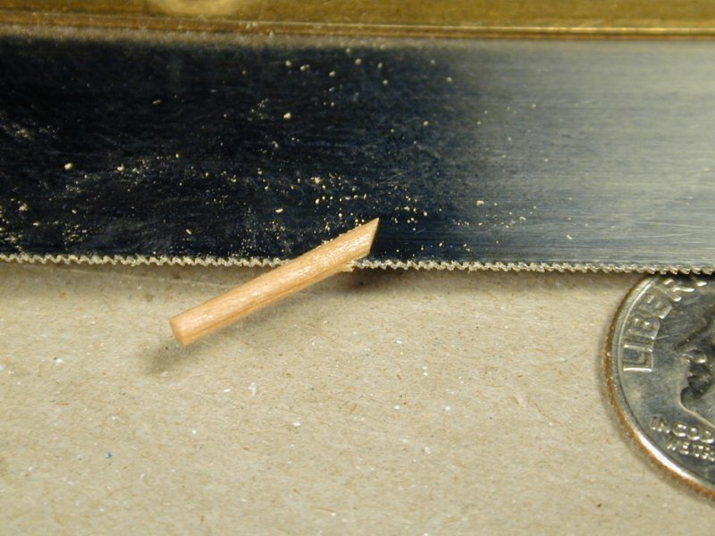
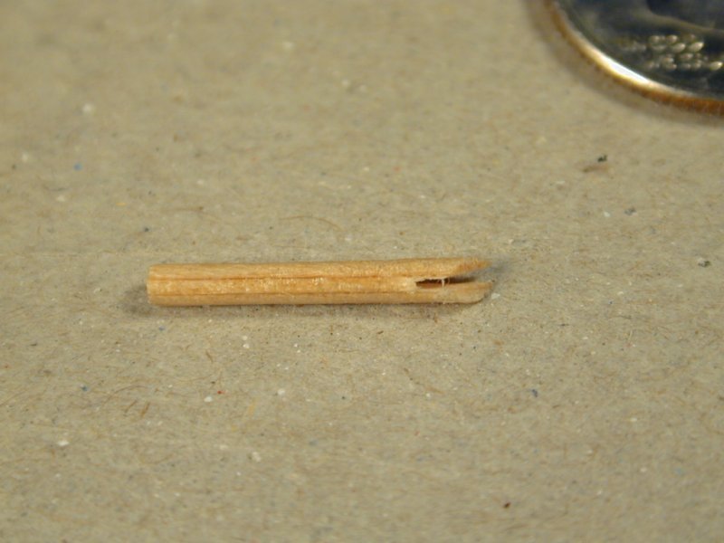
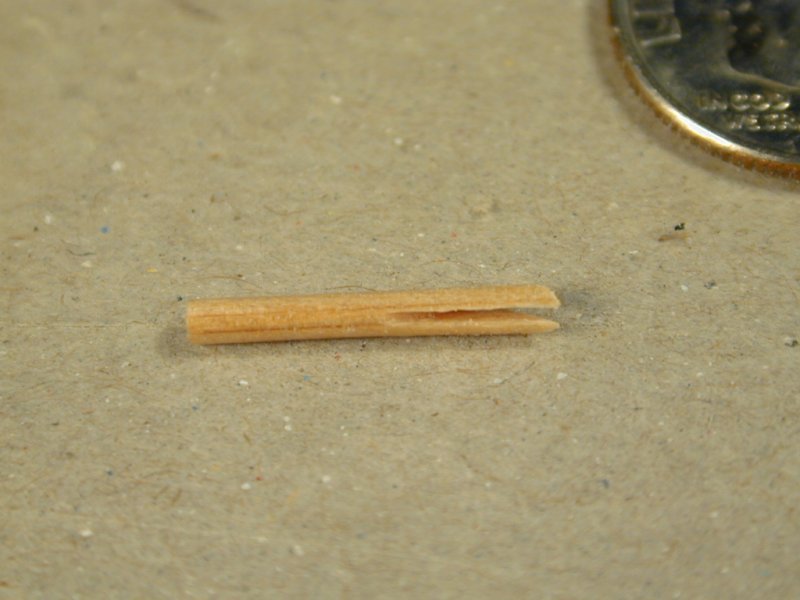
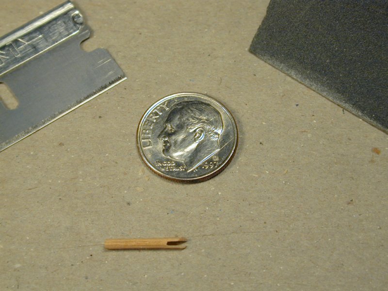
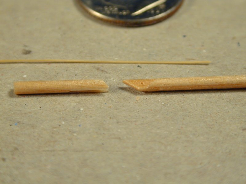
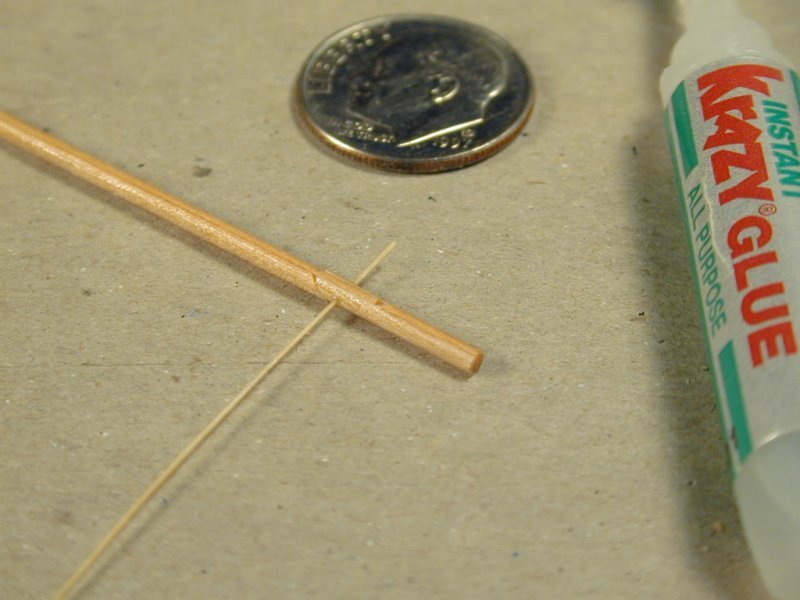
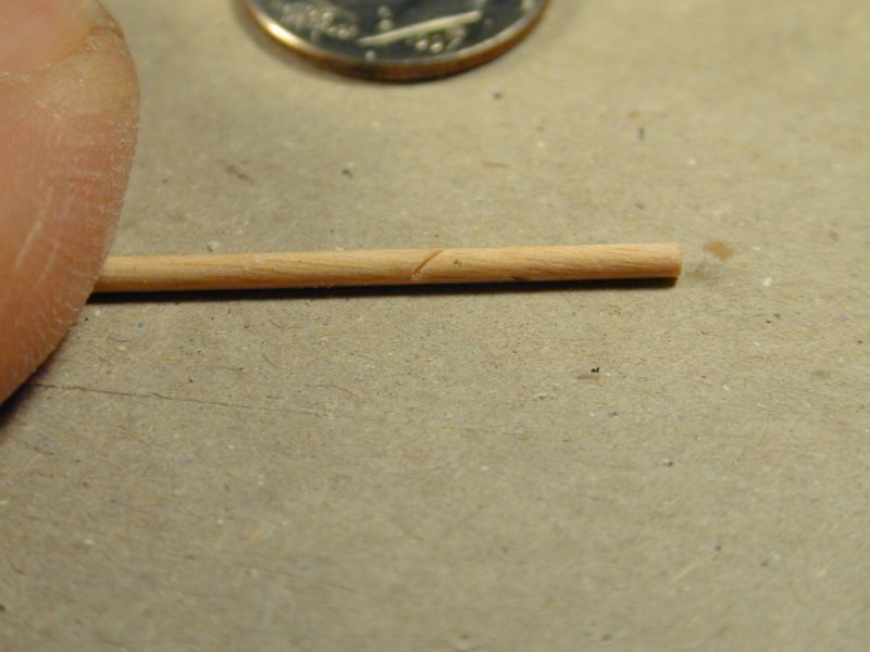
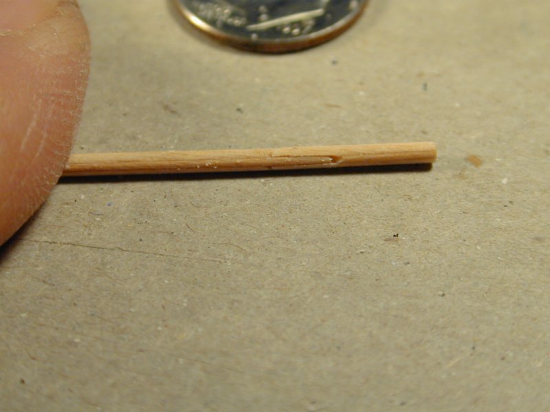
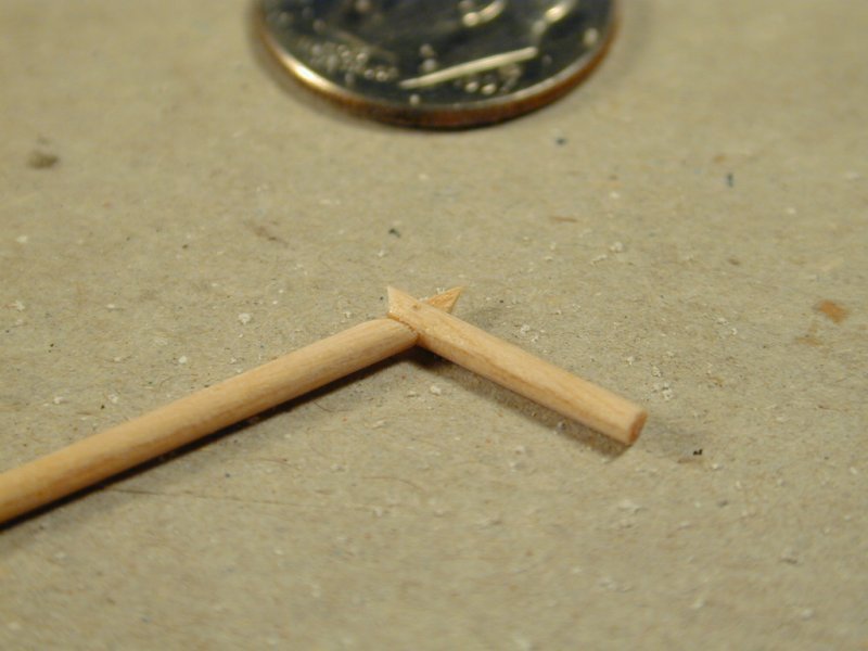
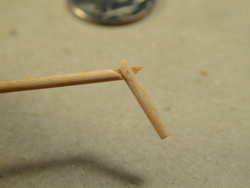
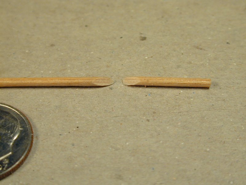
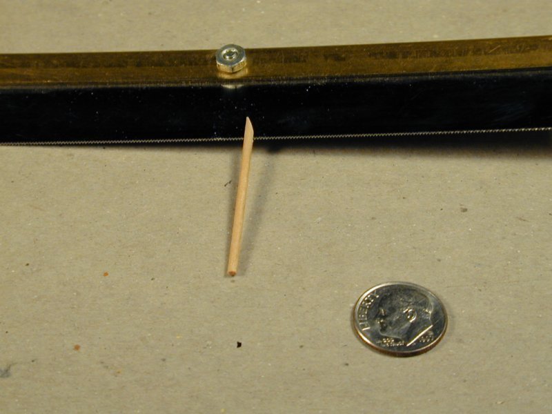
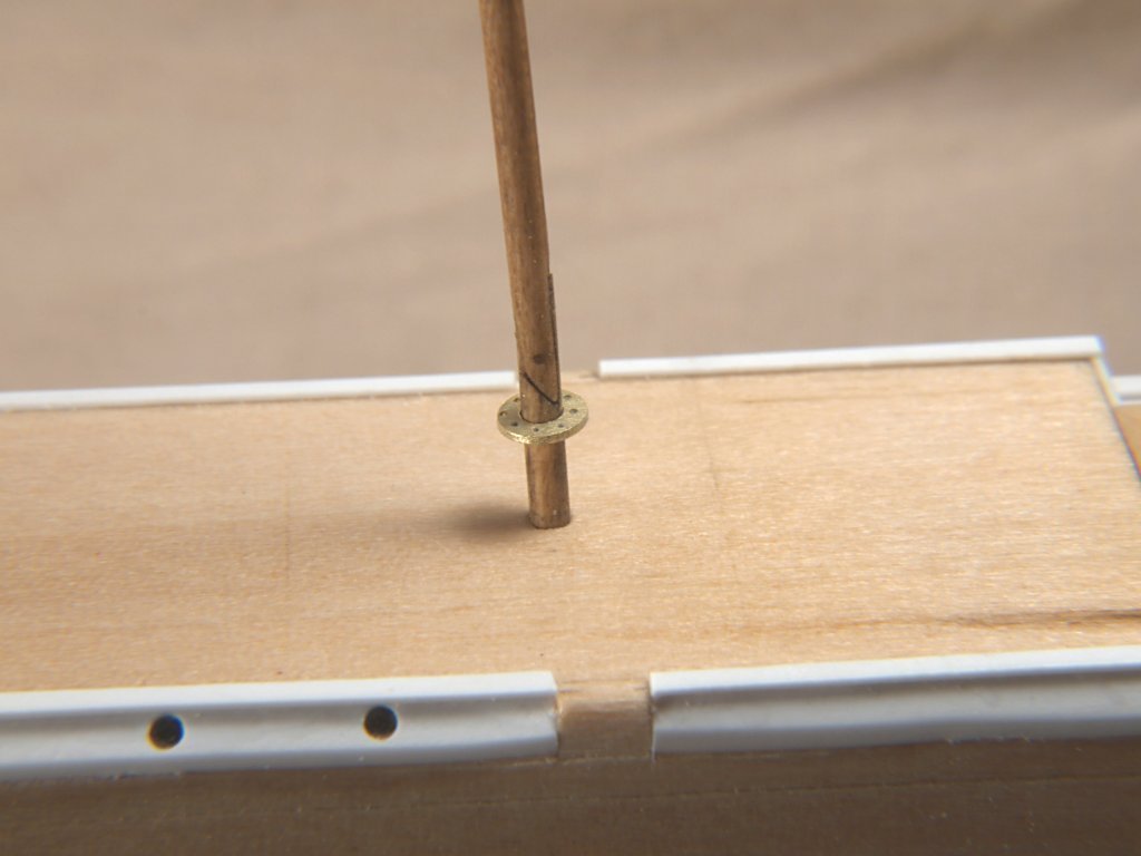
Greetings All, Since I showed the mast with the hidden hinge in my last posting, I will now show how those are made. The photos show the process pretty clearly. But happy to answer any questions. The wood used here is maple veneer, 1/32" thick. The last eight photos show an alternative method for a portion of the hinge. The hinge pin is made from drawn down bamboo skewer. Anchor's A Weigh! John Fox III

- 60 replies
-
- 11
-
-
-
Greetings Hashir, Thanks! We all start, started, in the same place. It's worth remembering that when you are a beginning modeler.
-
Thanks Keith! I do try! <Grin> Anchor's A Weigh! John Fox III
-
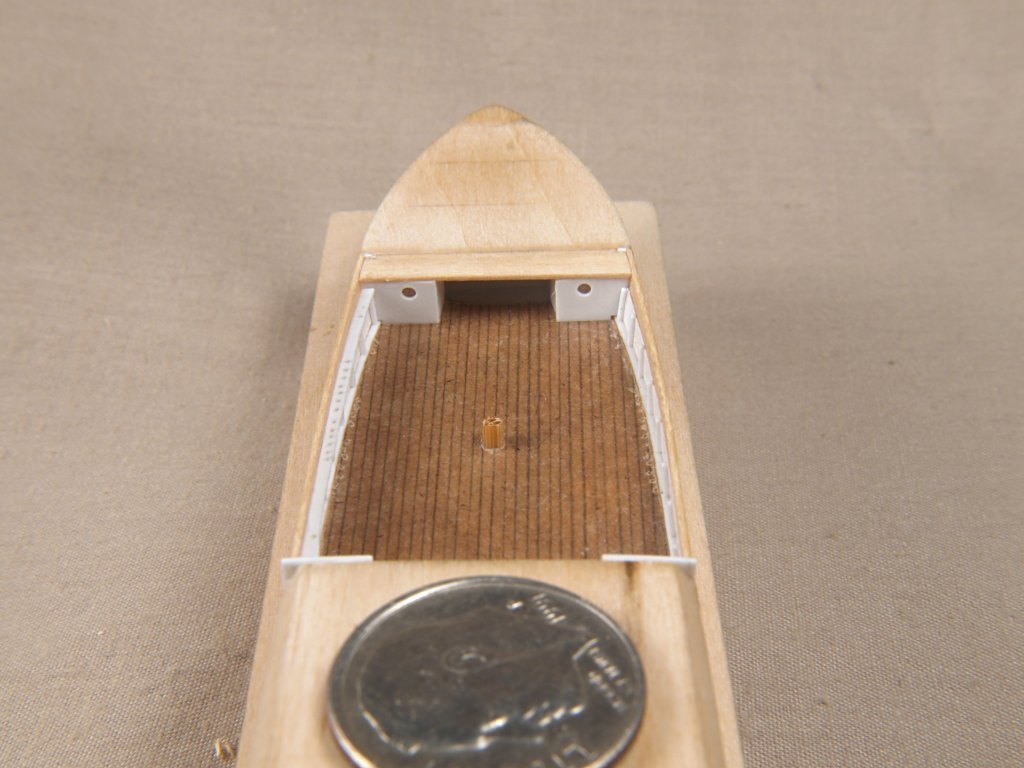
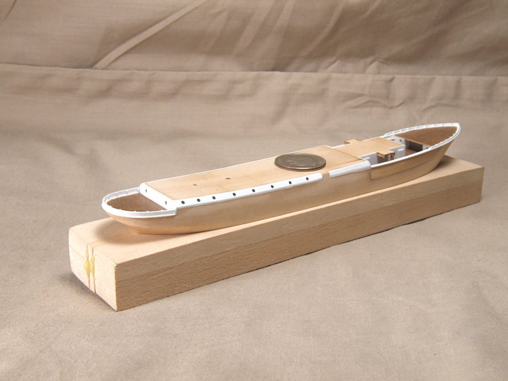
Greetings All, Previous photos of my Endurance light bulb model build showed the basic hull construction. The hull parts were made from basswood, with maple veneer bulwarks and forecastle extensions. The newest photos show further construction, including adding sheet styrene plastic inner bulwarks with frame extensions. The fore deck was made from thin paper with lines drawn on it. Additional sheet styrene detaling was added to the midships and stern, as well as forecastle bulwarks and keel, stem and stern posts. The prop was made from sheet brass, as well as the pin rails around the masts. The last photo shows the pin rail, and looking closely you can see the hidden hinge in the mast, which allows it to fold backward during insertion into the light bulb opening. Anchor's A Weigh! John Fox III
- 60 replies
-
- 11
-
-
-
Thanks Joe! I am flattered that a model of mine is considered legendary and saved in anyone's awesome model file! Anchor's A Weigh! John Fox III
-
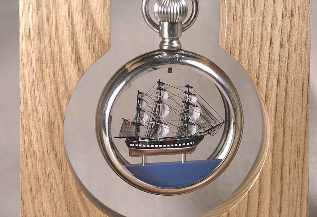
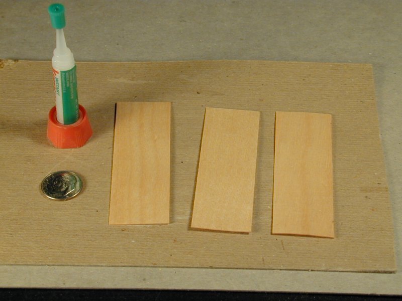
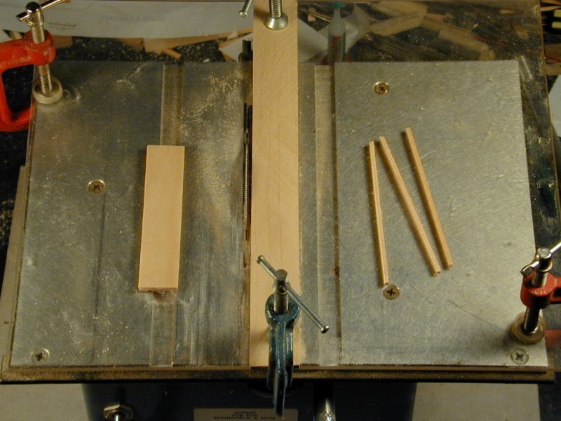
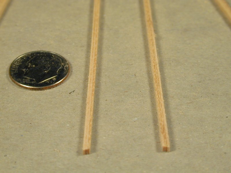
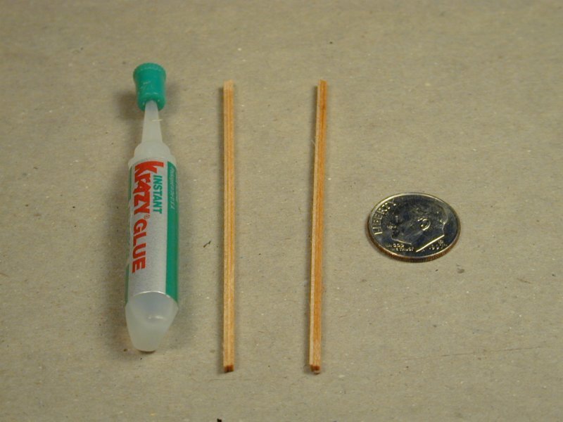
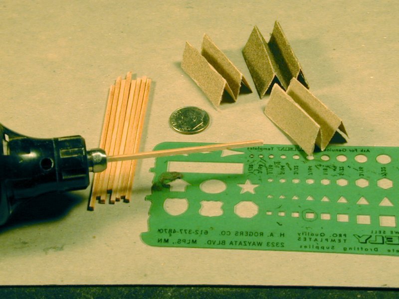
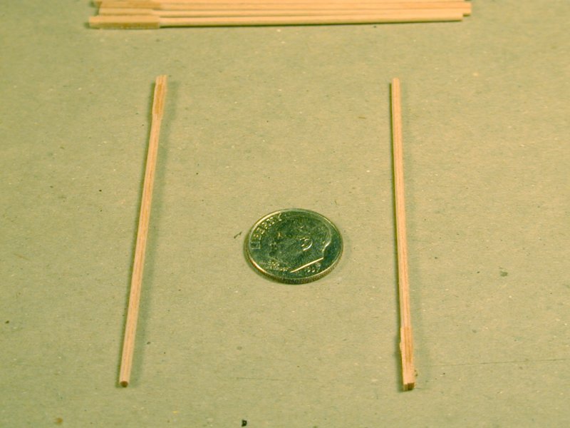
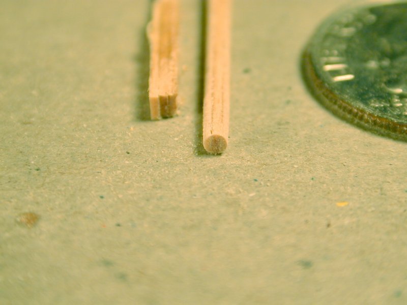
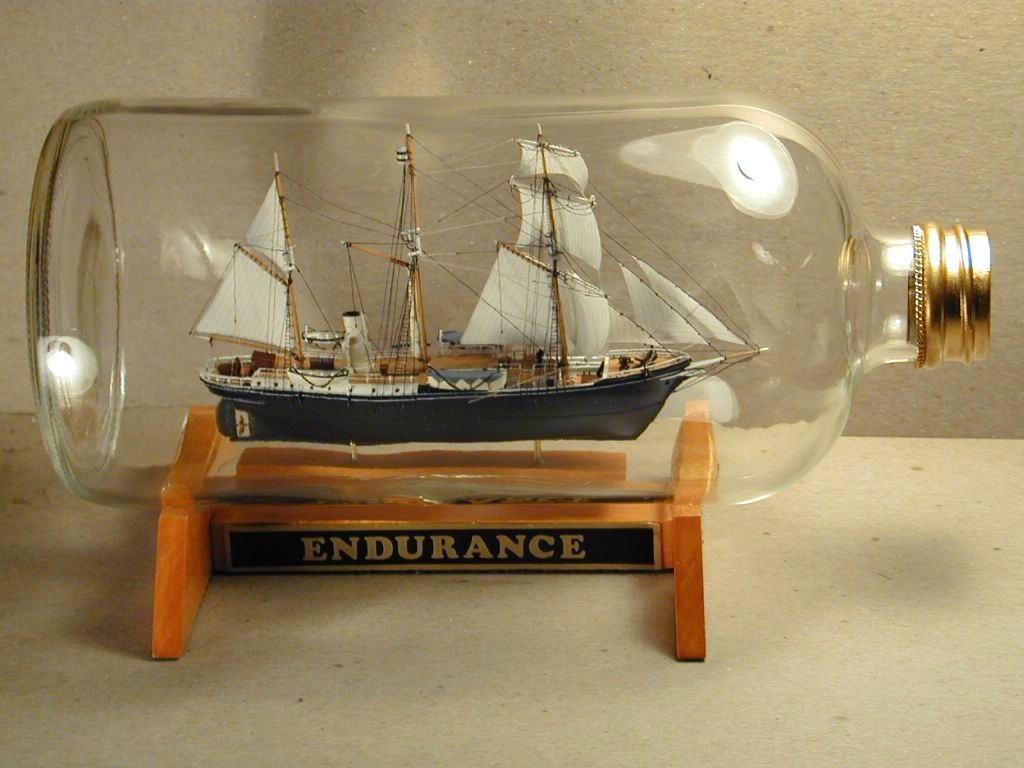
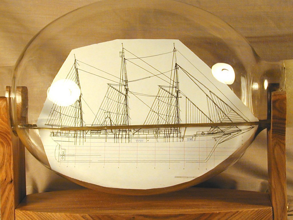
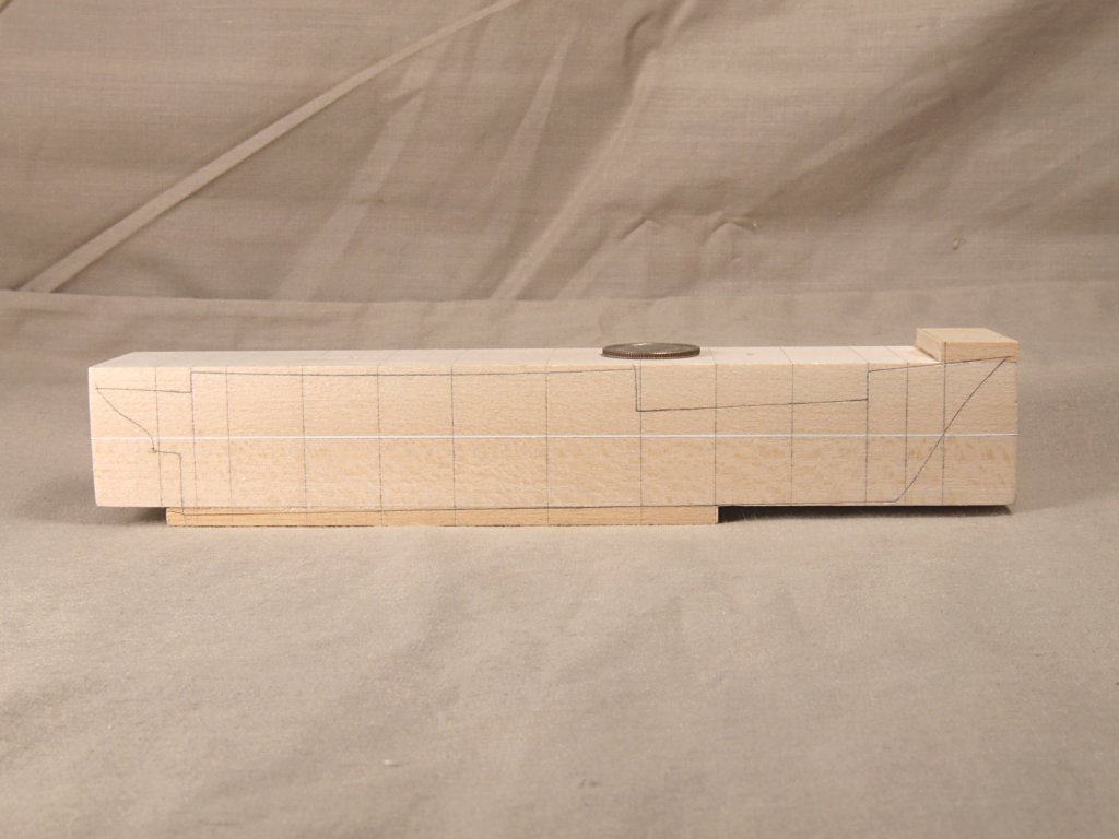
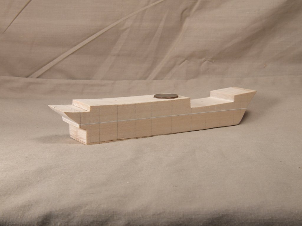
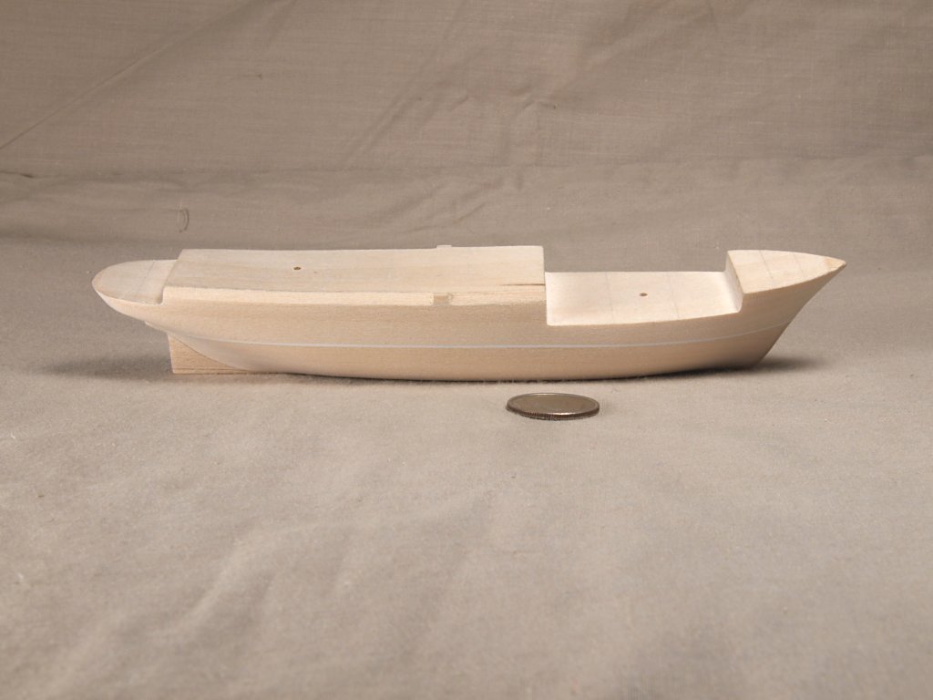
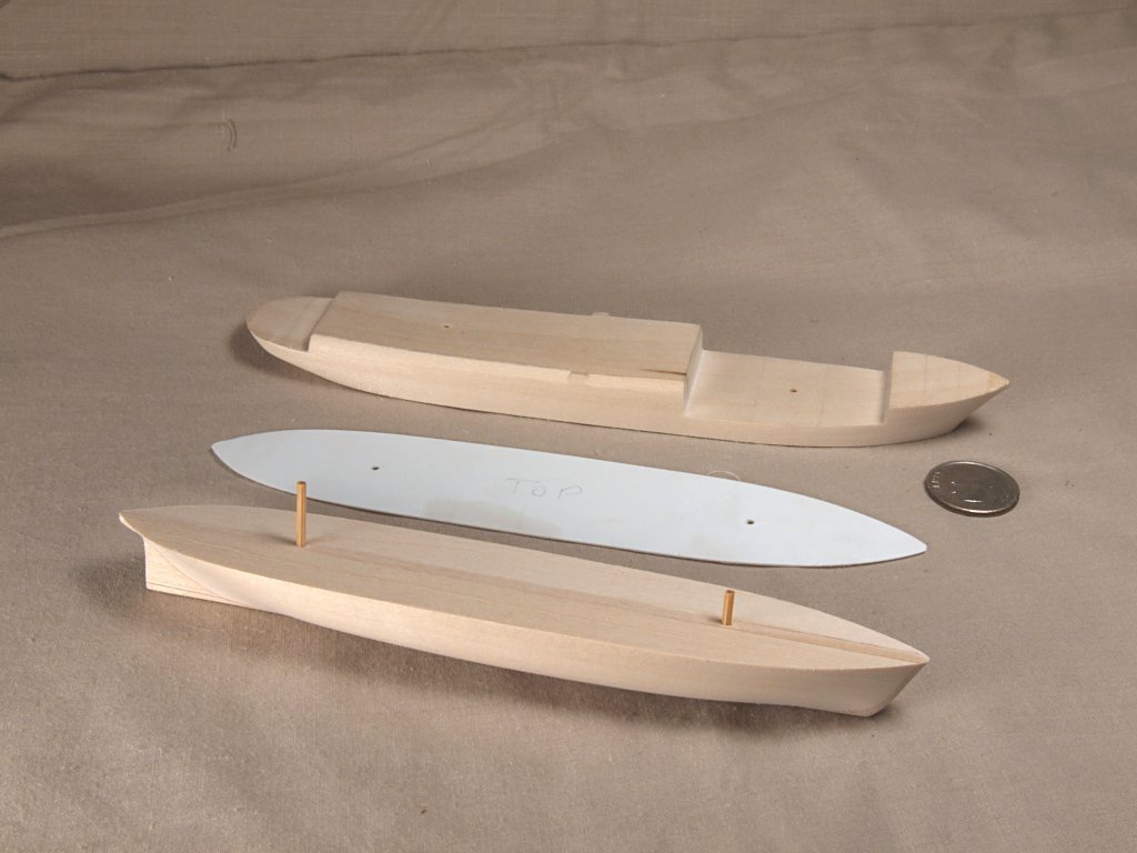
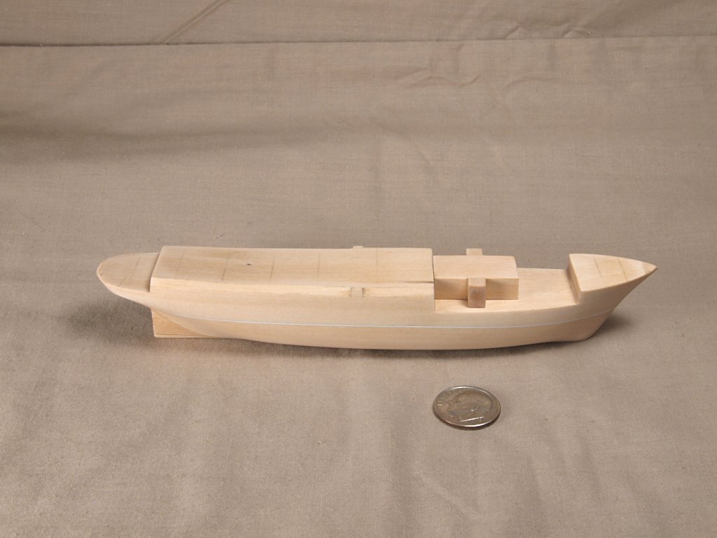
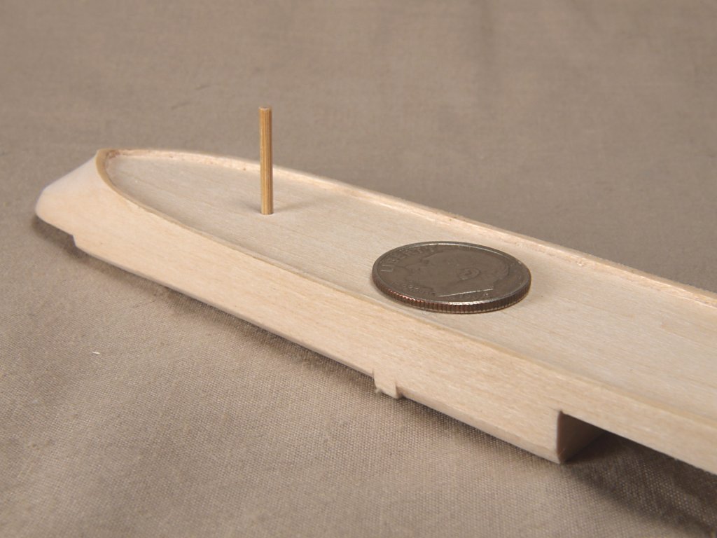
This is a log of the building of Endurance I constructed around 2001. A previous series of models were done at 1:350 as ship in bottle models. The first photo shows one of those. Most of this build log will be photographs taken while building the larger model, which was put into a sodium vapor light bulb with the end cut off. I will be happy to answer any questions. Endurance History The Polar Wooden Screw Yacht “Polaris” was built at the Framnaes shipyard in Norway, possibly in 1899. The Polaris was a 300-ton wooden barquentine, and never sailed under her maiden name. She was 144 feet long, built of planks of oak, and Norwegian fir up to two and one-half feet thick, and sheathed in greenheart, a wood so tough that it cannot be worked by conventional means. Polaris was built at a time in history when much of the world’s attention was focused on exploration of polar regions, both Arctic and Antarctic, with many expeditions from various countries attempting to reach the North and South Poles. One of the early explorers during this Heroic Age of exploration was Ernest Shackleton. In 1914 Shackleton proposed an expedition to cross the Antarctic continent, his expedition would require two vessels, one to take the men, equipment and the sled dogs to the Antarctic continent, and one to take men and supplies to the opposite side of the continent where they were to lay supply caches. Polaris was the vessel Shackleton purchased for the outward voyage, with an ex-sealing vessel, “Aurora” being obtained as the second vessel. He changed the name of Polaris to “Endurance”, after his family motto: “Fortitudine Vincimus - by endurance we conquer”. After much preparation, Endurance left her dock in London on August 1, 1914. The exact same day war was declared between many European nations, and World War I was begun. Endurance had not yet left British waters when the mobilization orders were sent out, so Shackleton offered his crew and ship for the British government's wartime use. The Admiralty decided that his Imperial Trans-Antarctic Expedition should proceed. Endurance set sail from Plymouth on August 8, 1914 on her voyage into history. Endurance sailed to Buenos Aires to pick up crew members and sled dogs and then sailed to South Georgia on November 5, spent a month re-provisioning while at this station and left Grytviken’s Cumberland Bay on December 5, 1914. Endurance sailed only two days before encountering the first pack ice. Endurance worked it’s way through pack ice for two weeks, passing many large ice bergs along the way. The ice and weather conditions worsened from about January 24 onward, and at times the crew would debark and attempt to chisel pathways themselves. By January 27, 1915 the ship was stuck fast in the ice. The fierce southern winter weather was causing further concern for all, as gales blew the pack ice into moving walls of destruction. The crew watched helplessly as huge chunks of some of the pack ice were moved and shoved into amazingly high stacks. In some cases the buildup of pressure would accumulate for a length of time causing massive ice movements in very little time when the pressure was finally released. For those living aboard Endurance it must have appeared all too clear what the gallant ship’s fate was going to be. The terrible winter weather continued for many more months. Endurance, and it’s crew, received both a great relief, followed by the worst moment in the voyage so far around the 10th of October. At that time the ice started to break up, and a new lane opened up that everyone thought had a chance of being navigated. This breakup was followed however by a severe wind, which piled the pack ice up beneath Endurance and lifted her above the water. The gallant ship was then heeled over on her port side by 30 degrees, before righting again when the pressure reduced. On Sunday October 24th Endurance was severely struck in the stern by no less than three pressure ridges of ice. The ship was listed over to starboard 8 degrees, and the stern post nearly twisted out of the hull. The vessel started leaking badly, and the steam engine had to be kept running to keep the pumps working. At 4:00 p.m., October 27, Endurance received a heavy blow, which knocked it’s stern higher, and completely tore away the rudder and stern post, the keel was ripped out and the water poured in. Shackleton and his crew lived on the ice nearby the Endurance for nearly one month before the ship met it’s final end. This came for Endurance on the evening of November 21, 1915, when the vessel rose by the stern and then slid down into the water. The Imperial Trans-Antarctic Expedition ended with the loss of Endurance, though Shackleton and his entire crew survived and were rescued. Ship In Light Bulb Model of “Endurance - Construction Ship in light bulb models have certain construction differences from static display models. The first consideration for construction of such a model is that the model, or it’s individual parts, must fit through the neck of the light bulb. For the Endurance model the type of construction used by this builder required that the finished upper hull of the model, including all masts, yards sails and all rigging lines, be able to be collapsed small enough to pass through the bulb opening. The lower hull and model base are separate pieces, that can be passed through the neck of the bulb individually. The base is then glued to the inside glass surface, then the lower hull is glued to the model base, the upper hull is then glued to the lower hull. A laminate block of basswood is made up and used to carve the hull. The upper hull is a single piece of the wood, the lower hull is three separate pieces glued together. The lower hull has a thin piece of wood in the center, flanked by two wider pieces, making the whole as wide as the upper hull piece. The two hull parts are held together by drilling a pair of holes, and tightly fitting bamboo pegs into the holes. At the time of making up this “hull block sandwich”, a sheet of styrene plastic is placed between the upper and lower hulls, representing the waterline of the hull. The hull shape is then carved out of this sandwich of basswood and plastic, using the thin center strip of the lower hull for the keel location and to mark the locations of the cross sections from the body plan. The styrene sheet waterline is also used as a guide for the templates made from cutting out individual cross sections from multiple prints of the body plan. This method of hull construction also allows the hull to be separated to make painting of the hull of the model easier. An air brush was used to apply the paint, and a protective sealer coat, to the hull parts. The scale of the model is 1:400, so some of the smaller detail trim was simplified. In order to make the upper hull small enough to fit through the bulb opening, the superstructure must be built in such a way that it is able to be collapsed. In order to do this, the masts have hidden hinges built into them. This allows them to pivot backwards, lowering their tops and all the sails and yards attached to them. All the square sails, and yards, on the fore mast must be attached to the mast in such a way that they can rotate parallel to the mast along the length of the hull, so that they too will fit through the opening in the light bulb. The Endurance model’s hidden hinges are carved into the masts by making a lower piece that has a two pronged “forked” top that fits around a single center stem on the lower end of the upper mast piece. A simple drawn down bamboo pin is then inserted into a hole drilled through the center of the overlap, where the upper mast piece fits into the fork of the lower mast piece. This allows the masts to break at a point well above the deck of the model, which was critical with the cabin structure directly behind the fore mast. All the spars for the Endurance model were made from glued laminates of maple veneer. The resulting glued joint helps to strengthen the thinner spars, allowing the necessary rigging line holes to be drilled without splitting them. Pieces of veneers of maple are glued together, then strips are cut from them. The strips are then “spin-sanded” down to nearly their largest diameter, by chucking them into a Dremel moto-tool and using folded sandpaper pinched around the spinning mast blanks. Final sizing and shaping of the spars is done by hand sanding. Any necessary holes in a spar are drilled before the hand sanding, when the spars are a bit larger in diameter. This laminate structure for the masts made it much simpler to carve the necessary parts of the hidden hinges in them. Most of the rigging lines on the Endurance model are working, or control, lines that are used to bring the masts up into their raised positions. Control rigging lines are also used to pull all the sails, booms and gaffs into correct position after the masts are raised. Most of the control rigging lines are rigged and worked the same as the actual running rigging lines on the real vessel.. All control rigging lines run through holes in the bulwarks, a fife or pin rail, the bowsprit or some other spars, before finally passing through the hull at the deck or other location. The control lines pass through the hull into a hollowed area carved into the underside of the upper hull. This allows the lines to pass forward from their entry point and out through the hawse holes on either side of the bow. The model was assembled inside the light bulb, with the ends of all the control rigging lines left outside the bulb. Several rubber bands are then wrapped around the lines and the neck of the bulb. This keeps the lines taught after they are tightened to pull the various parts of the model into proper final position. At every accessible point that a control line passes through a spar, a rail or the deck of the hull, a tiny amount of glue is applied to hold the line in place, once the lines are taught. When all the glue had dried, the excess control rigging lines were cut off as close to the hawse holes as possible. The small amount of these lines that remained were stuffed back inside the hollowed area beneath the upper hull.
- 60 replies
-
- 16
-
-
-
Greetings Wintergreen & Tony, I do CAD ship plans often, one tip I would suggest is to save the tracings of the existing plan images, then continue working in your normal methods. If at any future time you find an error, simply go back to the original traced and saved drawing. No need then to retrace anything. I often save my plans whenever I make any big new step in their preparation, allowing me to "go back" to any previous point. I simply save the file under the ship name with a number, and keep increasing the number each time I save. Anchor's A Weigh! John Fox III
-
Greetings Pierre, Welcome aboard! Looking forward to seeing your model of BHR. I built a ship in light bulb model of that vessel a few years back. Anchor's A Weigh! John Fox III
-
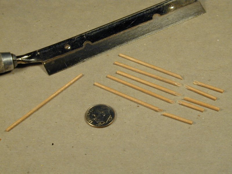
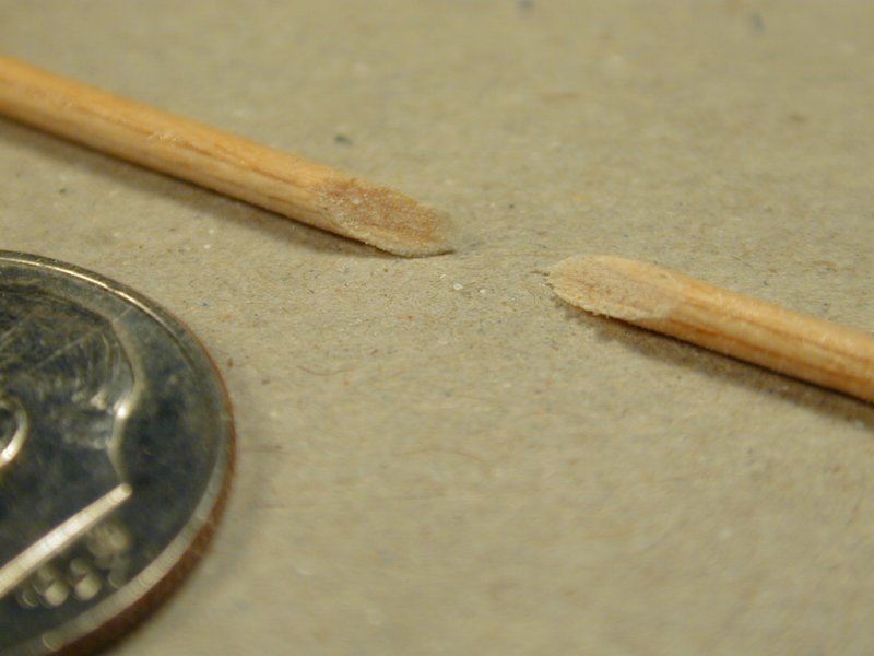
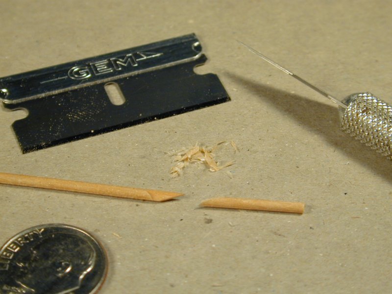
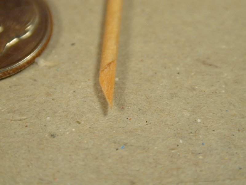
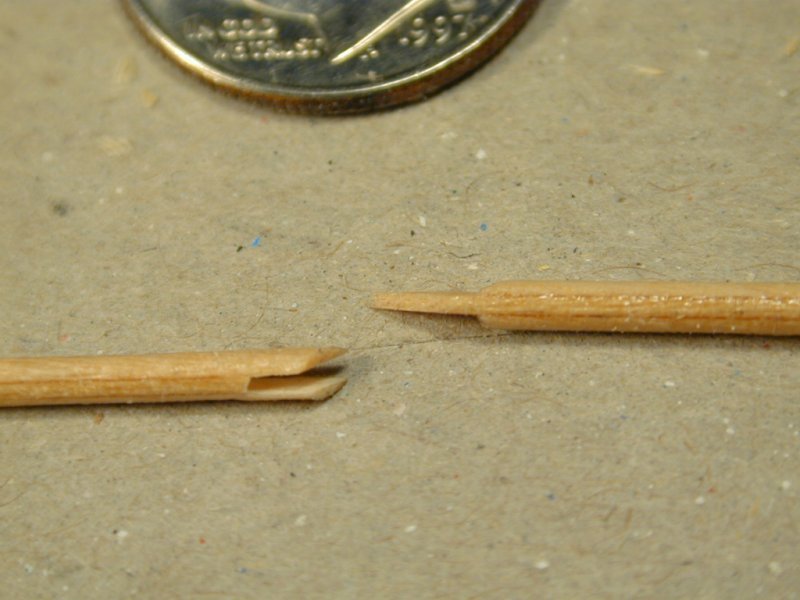
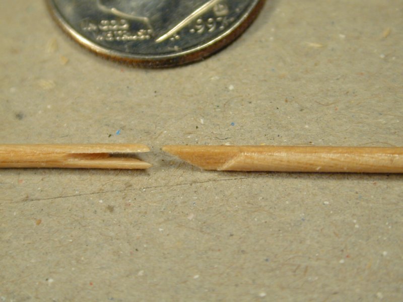
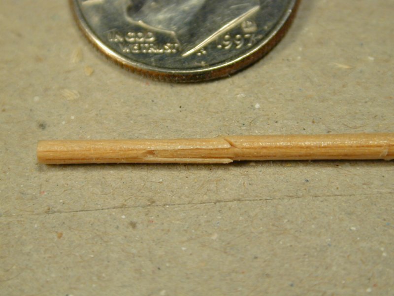
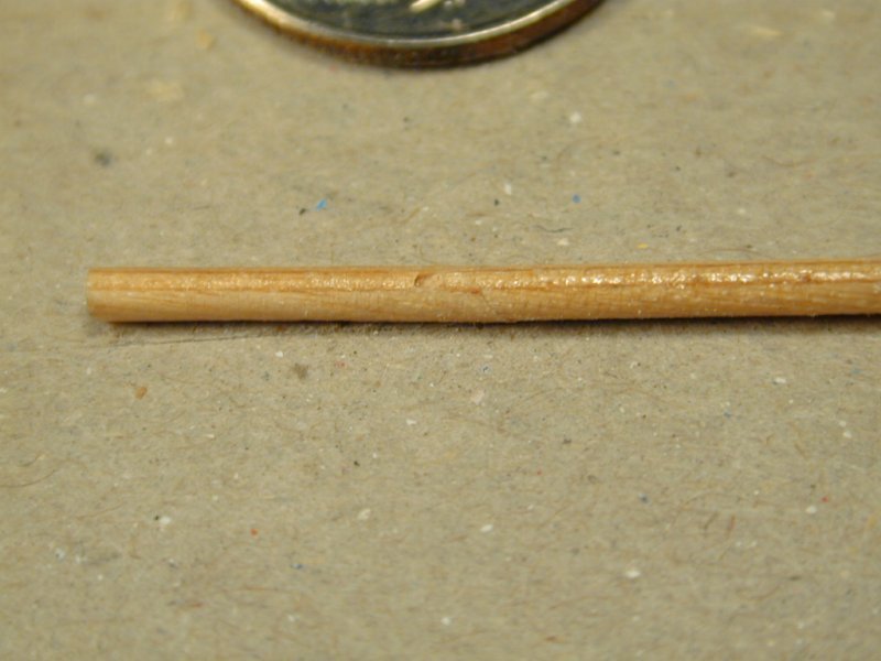
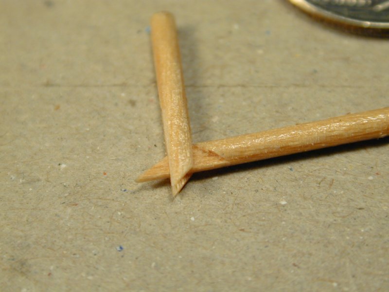
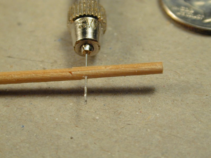
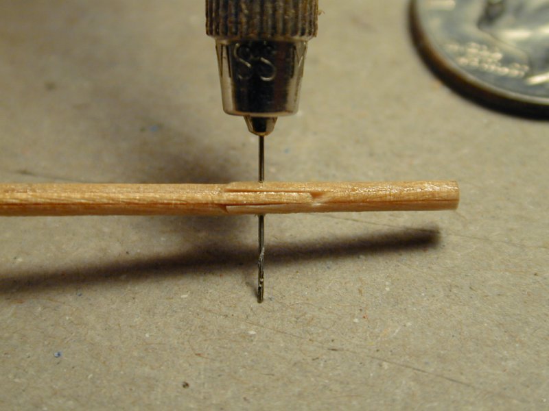
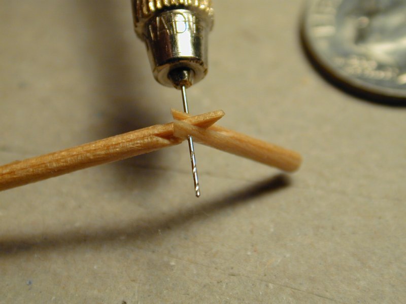
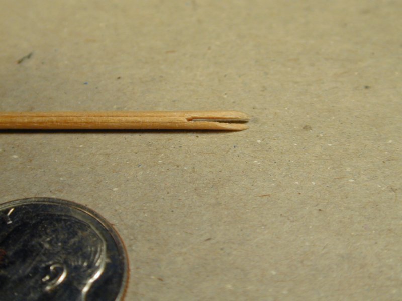
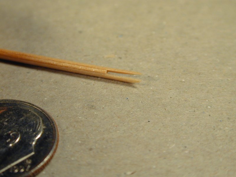
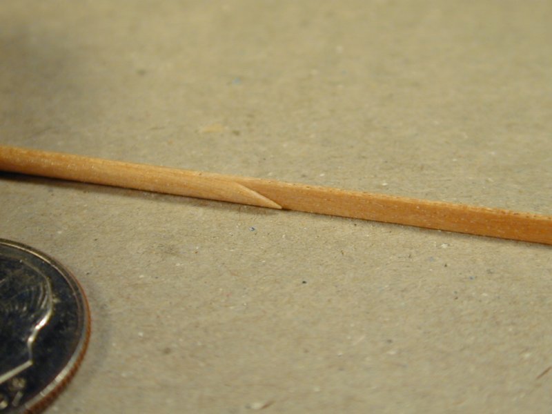
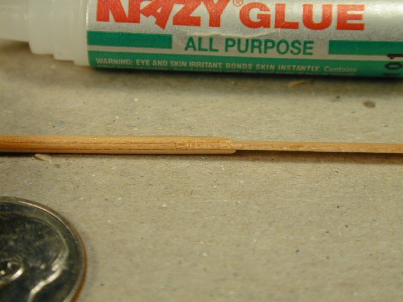
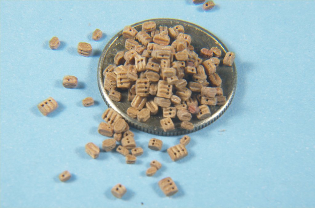
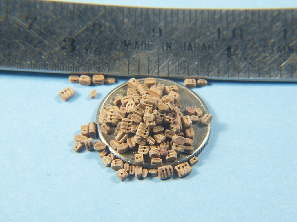
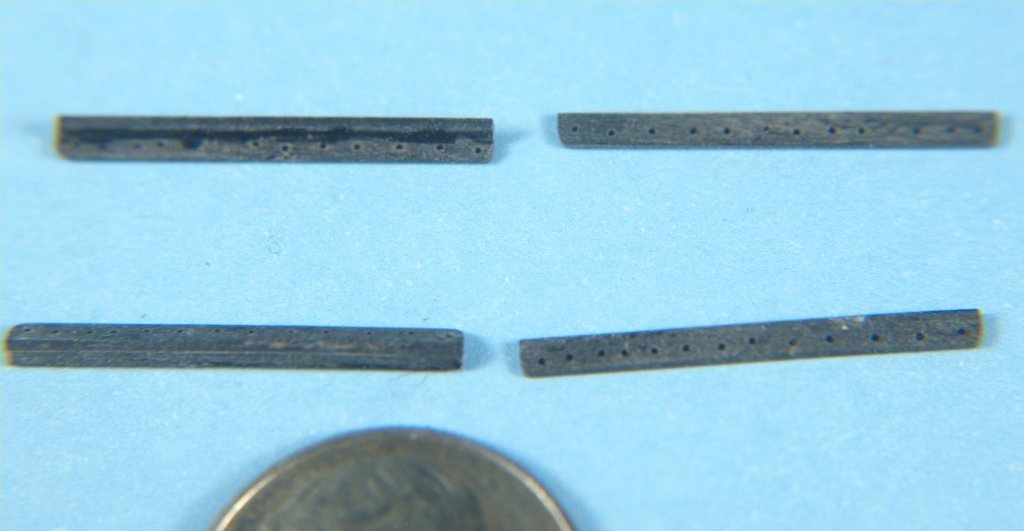
I've recently had need of some tiny wooden fake blocks for a 1:92 scale model of a ship from the early 1800's. A few photos of well over 100 single/double/triple block are attached. They are made from rectangular sticks of apple wood, the stropping groove is made on two sides with a triangular miniature file. The hole[s] are drilled, then the end near the holes finished off with fine sandpaper. The end was then cut off, and that end shaped with sandpaper while being held in a very fine tweezer. A second tweezer with teeth was used to hold the block with the holes up, and the drill bit in a pin vice was used to cut the grooves for the rigging lines. The blocks in the photos are sitting on top of a US dime, about 3/4" in diameter. There is a rule in the second pic for size. They amount to around 6", 10" and 12" at scale. Anchor's A Weigh! John Fox III
-
Personally I use QCAD for plan drafting. It is limited to 2D drawing, but I can import .jpg/.jpeg files of scans of printed plans and trace them. They used to have a free version, not sure if they still do, but I only paid $40 US for the full version. It is similar in use to AutoCAD, but vastly cheaper. As with most CAD programs, it takes some getting used to, but if you've ever used a CAD program, or spent time with pencil/pen and paper to do drafting it's quit easy. Anchor's A Weigh! John Fox III
-
C. The bolt rope goes around, stitched to, the entire perimeter of the sail, top/bottom and both sides. Basically it completely surrounds the sails, as Allan says it is stitched to the outside perimeter. The line you outlined above is just part of that bolt rope. Allan Simply make a loop of line as long as the perimeter of the sails, adding blocks where necessary to run rigging if there was a real sail. Unfortunately, no photos as when I did make larger scale models without sails I had a very old, limited digital camera and only have entire model shots. At the top edge, i.e. at the yard, the bare bolt rope can be laid along the yard and wrapped as if there was a sail, or attached to the jack stay if the yard had them, just as if there were a sail attached to the bolt rope. For jib sails it's the same, add blocks for the sheet lines and uplift/downhaul lines at the bolt rope corners, plus rings or lines tying the bolt rope to the stays. Anchor's A Weigh! John Fox III
-
There is a bolt rope attached to the outside perimeter of sails, to which blocks and lines were attached. When I built models without sails I added just the bolt rope, which allowed me to include all the sail rigging to the model. Anchor's A Weigh! John Fox III
-
Greetings Seahorse, Very impressive! I just finished doing some experimenting with card stock modeling, but could do nothing as impressive as your work, congratulations on a super well done model! Even more impressive is that you designed it all yourself. Are you using some sort of software like Delftship or Freeship? Reason I ask is that you have worked out all the planking strips to such precision. I tried using those myself, but could not get good enough results. Thanks for sharing your impressive work! Anchor's A Weigh! John Fox III
- 14 replies
-
- 2
-
-
- sao gabriel
- caravel
- (and 3 more)
-
Experiments in Card/Paper Modeling
John Fox III replied to John Fox III's topic in Card and Paper Models
Thanks Crhis, glad you liked it! Anchor's A Weigh! John Fox III -
Experiments in Card/Paper Modeling
John Fox III replied to John Fox III's topic in Card and Paper Models
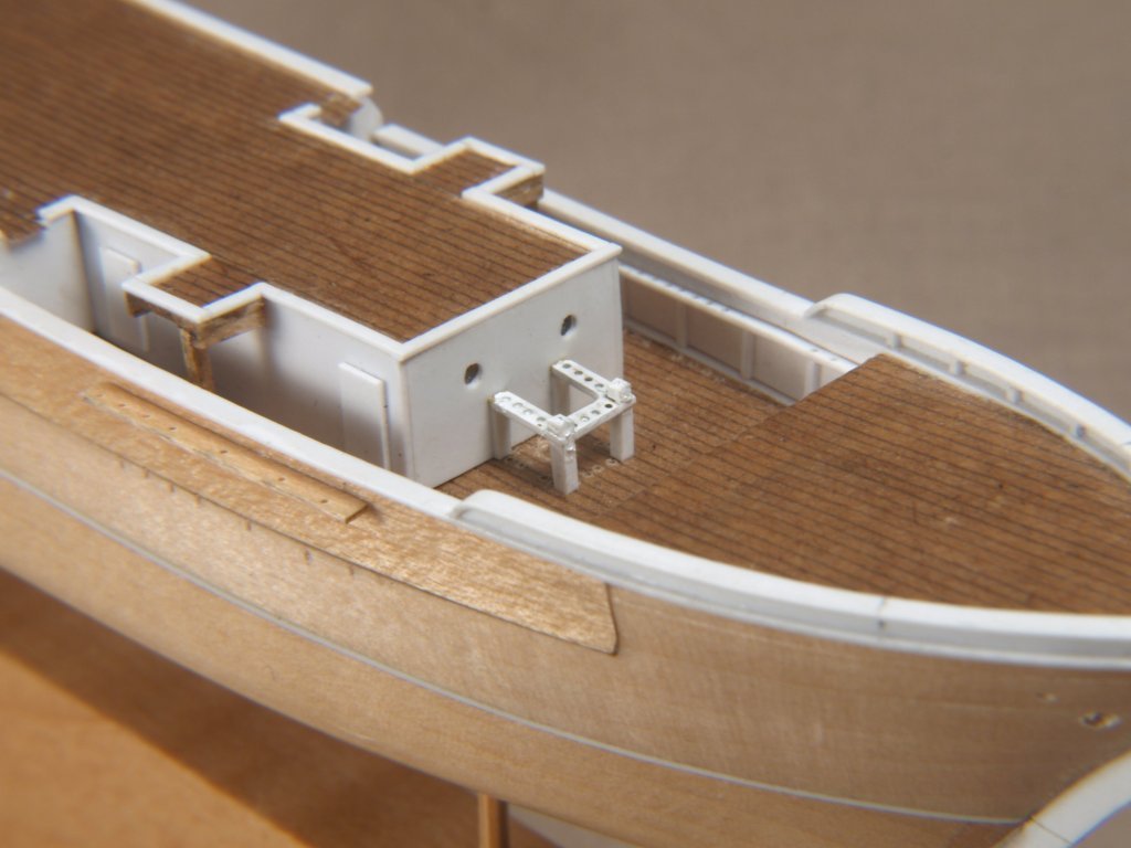
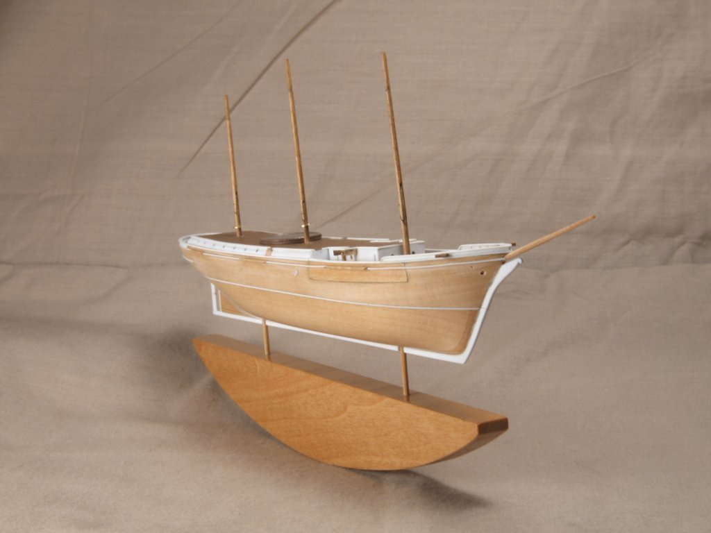
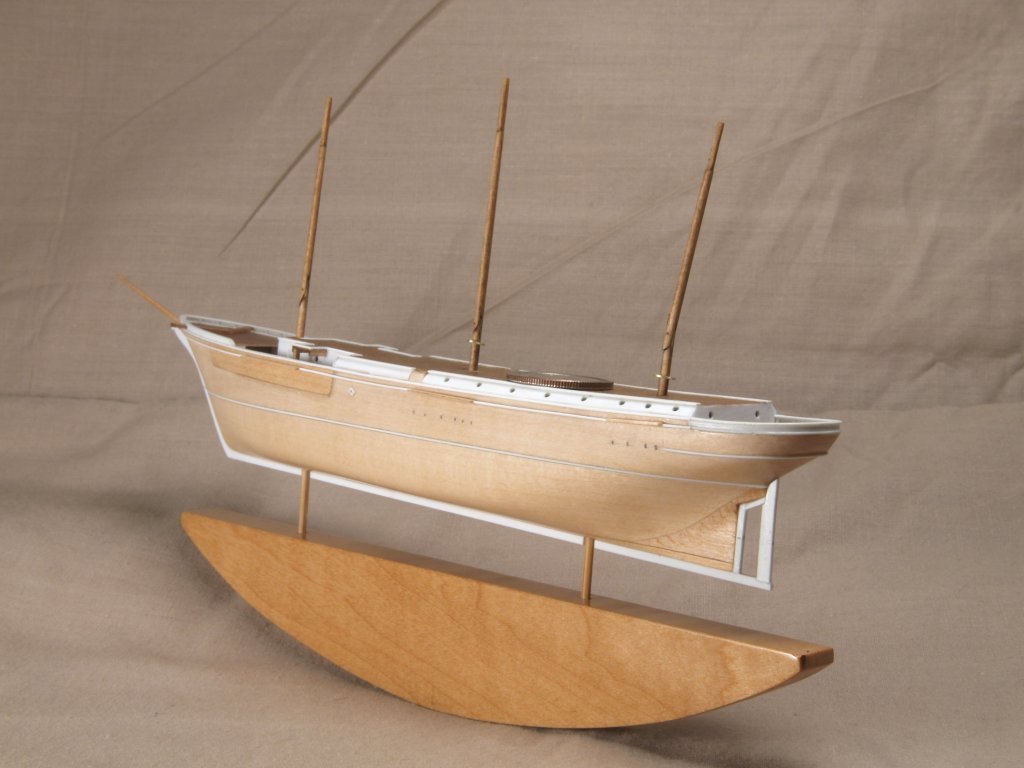
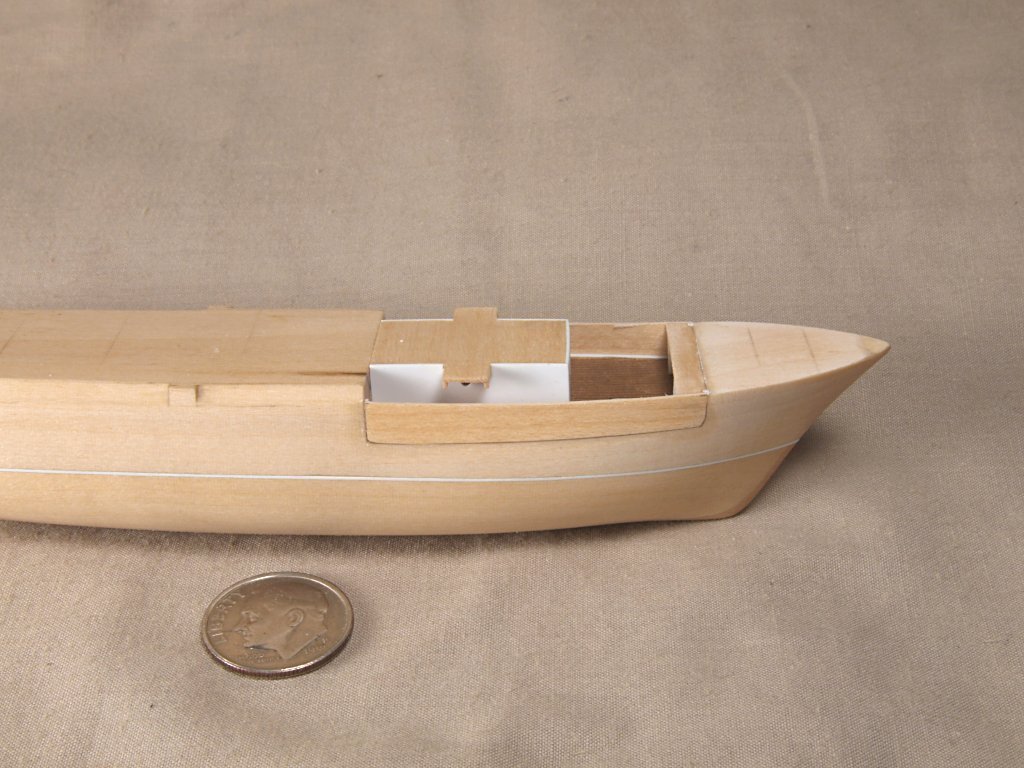
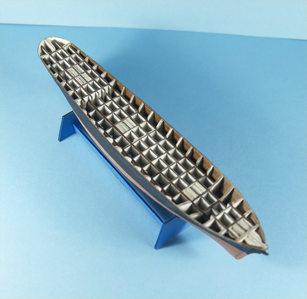
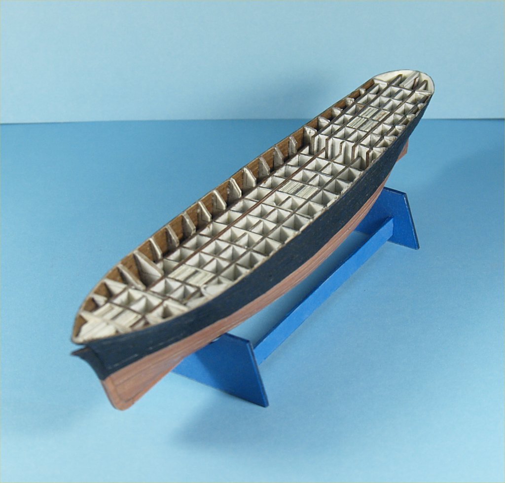
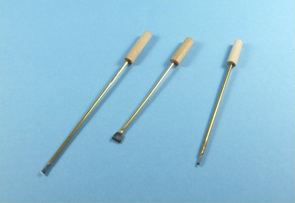
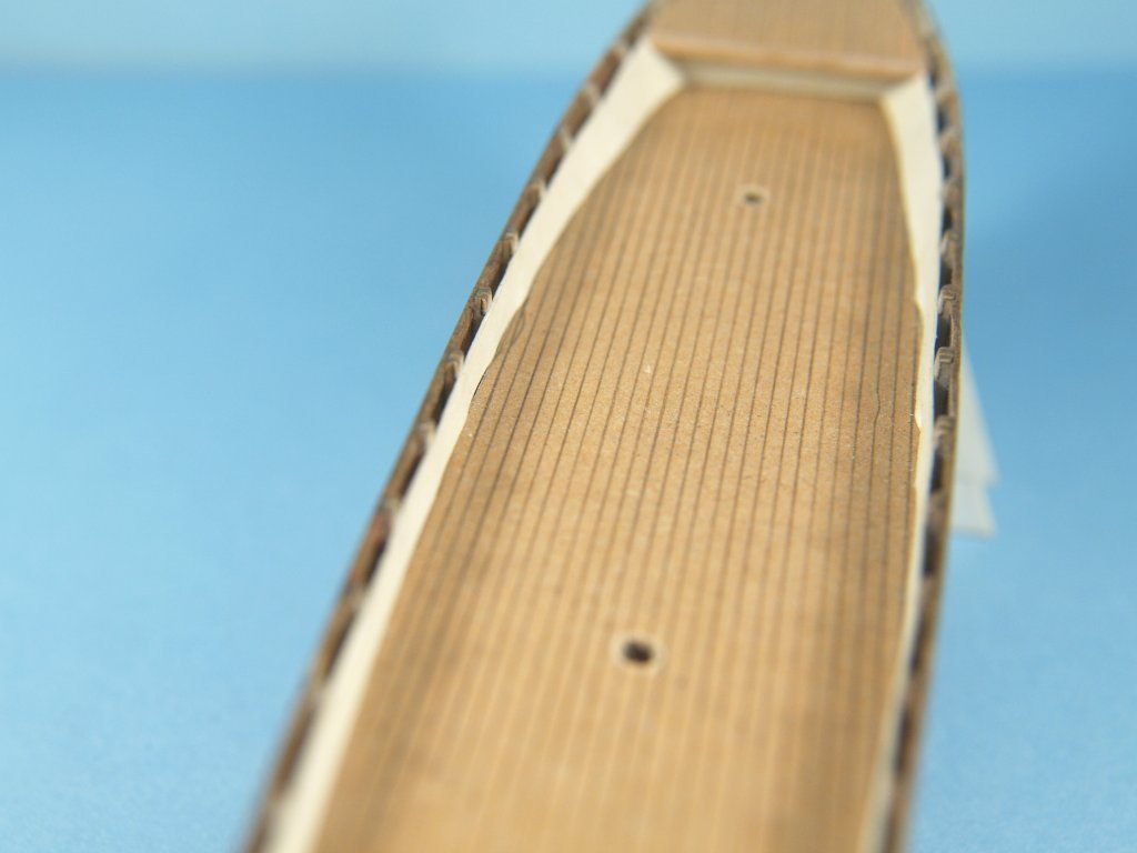
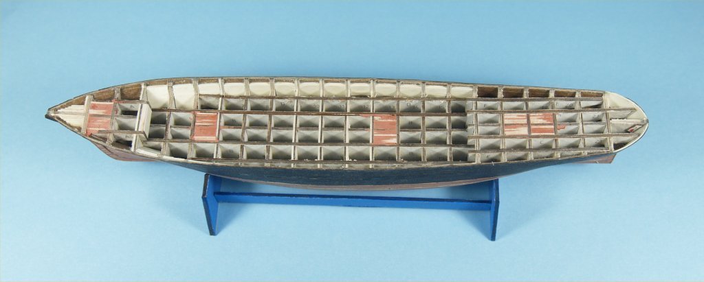
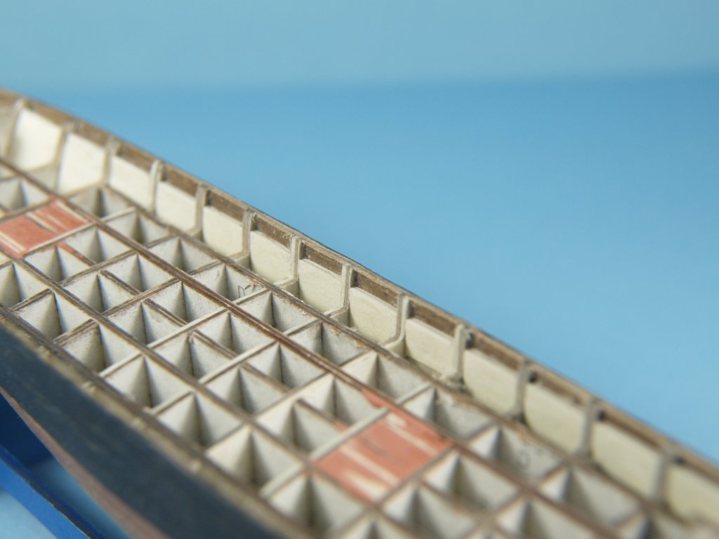
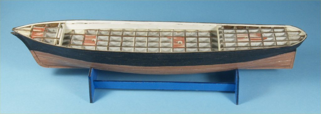
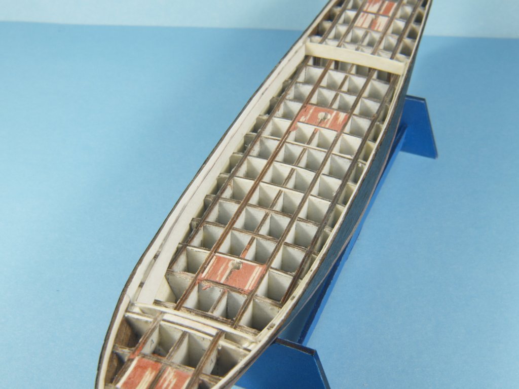
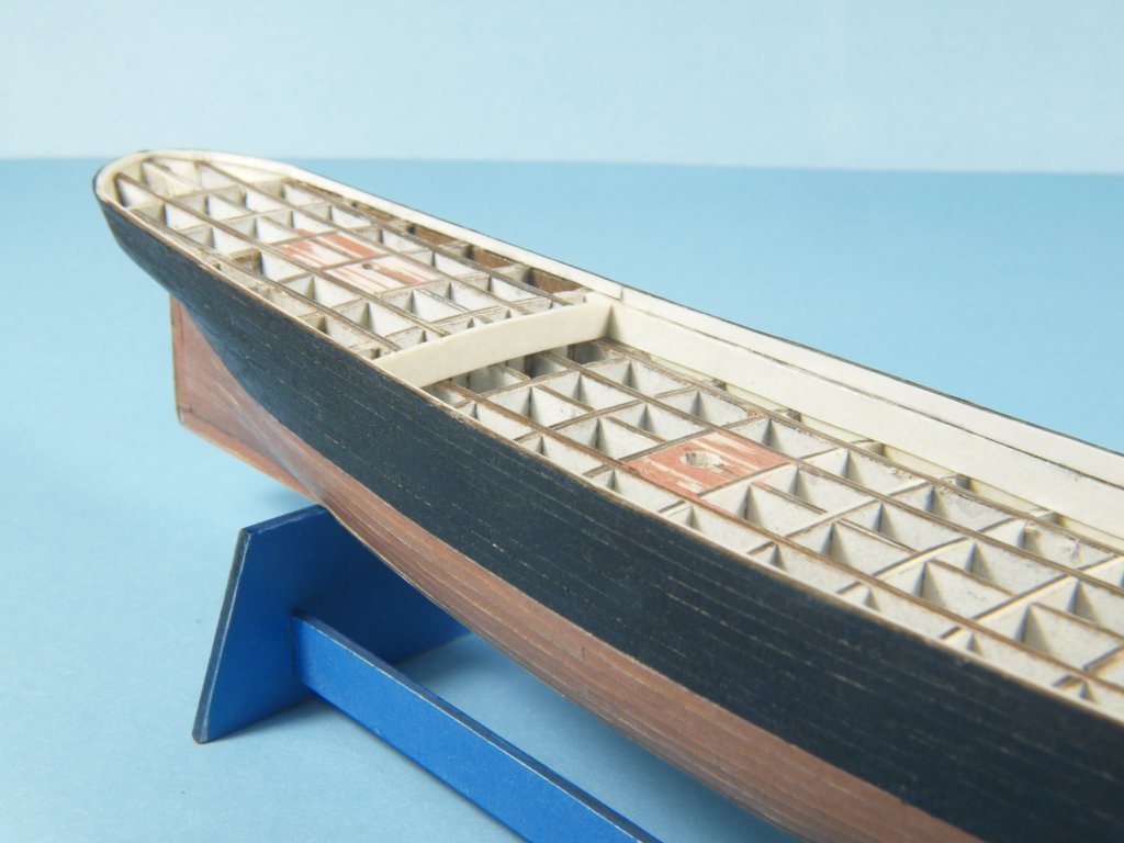
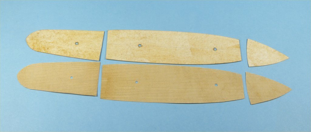
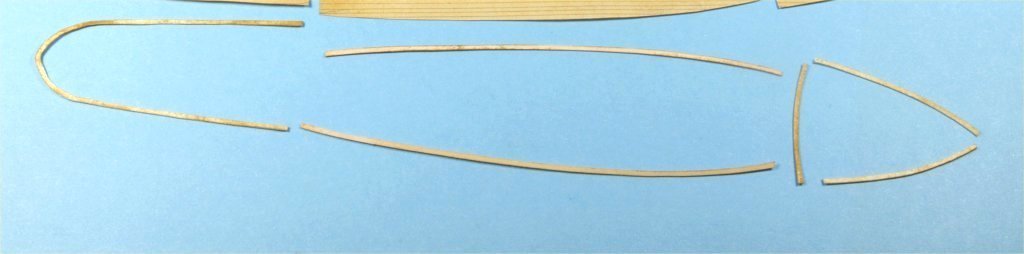
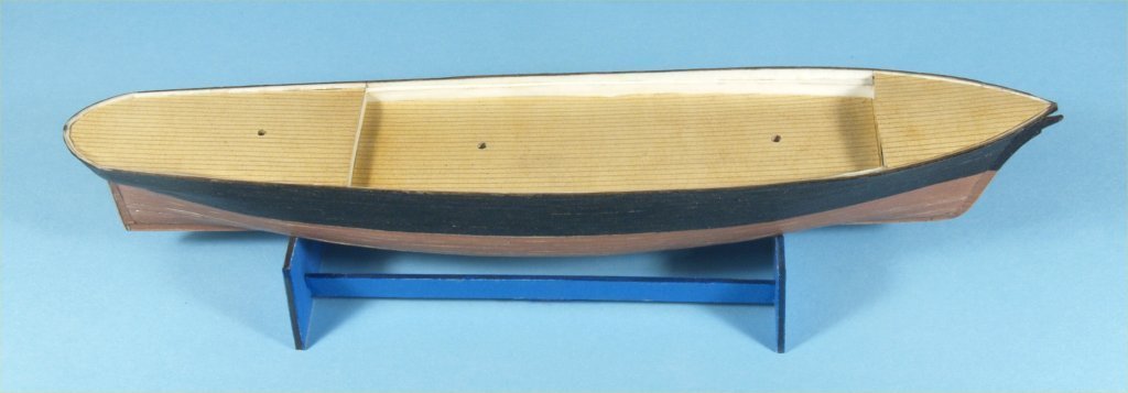
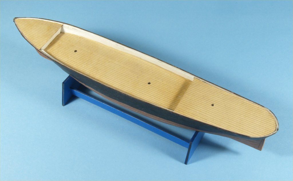
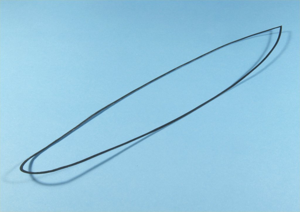
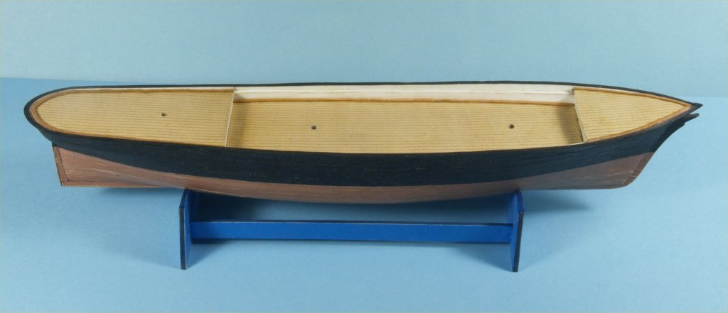
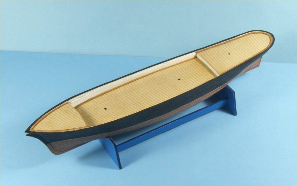
My work on experimenting with card/paper model ship building continued with finishing up the second hull, the one with colored card stock second planking. The hull was cut free from the building board by slicing through the bulkheads at the top of the bulwarks. A simpler stand for the hull was made from blue colored card stock. The following photos show the freed second hull in the stand. The photos above show that I also added card stock blocking at the extreme bow and locations for the 3 masts. The multiple longitudinal bulkheads definitely define the deck areas much better than the first hull in my opinion. Work progressed with cutting down the interior edges of the bulwarks, removing the excess stock that was included in the bulkheads to make the hull more stable during planking. I used several tools that I built, made up from pieces of 1/16" interior diameter brass tubing and pieces cut from a single edged razor blade, with wooden handles made from maple. I used a Dremel moto tool with a cut-off wheel to cut the razor blade pieces of various widths at the cutting end. I shaped the other end into shanks that would fit into the brass tubing, then slid them in and glued them in place. These miniature chisels work nicely, and I've used them on many models in the past. The photo above shows how the interior planking of the bulwarks on the first model's hull turned out. I was not happy with these results, the uneven run was the result of not quite having faired the bulkheads properly, and partly due to the miniature clothes pins used to clamp the single piece planking in place. I decided that on the second hull I would experiment in ways to improve these problems. I ended up filling in the gaps between bulkheads with card stock before final sanding the bulkhead interior sanding. This definitely helped even things out, and kept the clamping devices from indenting the interior planking pieces. I did the same thing for the stern of the fore castle deck and fore face of the quarter deck as well. The following photos show this work. I then proceeded to cut away the tops of the bulkheads above my blocking. I decided that with the double layer of planking, the bulwarks would be thick enough with just a single layer of card stock glued inside. The next work was to cut and glue the white interior planking. This was a process of using paper to make templates and then transferring those outlines to the card stock and cutting. These strips and pieces were then glued in place. The results were much better than the first hull at this point. I also drilled the holes for the masts. The following photos show this work. Work continued on this second hull with making paper templates of all the decks. These were traced on stained white card stock and stained white paper with planking lines drawn on it. All of these parts were cut out and fitted to the hull, to make sure they fit properly. I then stained more white card stock, traced the deck parts and cut out some waterways for the model. I was not happy with the way these waterways looked, they were a bit too wide and attempting to cut or sand them thinner just didn't work. I decided to remake the waterways by staining a piece of white paper and then gluing them to card stock and cutting them out. These looked much better, but are still probably a bit too wide for this scale. The decks were then glued to the hull. The following photos show this work, the waterways photo shows the first ones made, I simply forgot to photograph the final waterways. The most challenging work on this second model hull was my next work. I used black card stock to make the cap rail for the hull, in a single piece. I placed the card stock on the top of the model, held it in place with a stiff piece of thick cardboard pressing tightly enough to follow the entire curve of the top of the bulwarks. I traced the outline of the bulwarks onto the stock and cut it out. I used a small compass to then traced a line 1/16" inside the outer edge of the stock. The difficult part was to cut out this inside edge as carefully as I could. I can say that it took 3 attempts to get past this last step, as noted above with the waterways it is nearly impossible to re-cut or sand this thin card stock if any spots were too wide. I did use a black magic marker on the cap rails edges, as this stock has a white interior. The waterways and cap rail were then glued onto the hull. The results are shown in the next photos. At this point I believe I will be ending my card stock and paper modeling efforts. I found it very interesting, and in some cases rewarding, to have attempted this work. My personal conclusions would be that I definitely would rather work with wood, it's more stable and easier to "work" than card stock. I was surprised at how well some things worked, such as making up the masts and yards. But during building and fitting to the second hull I have already broken several of the yards. Saturated construction paper is just too brittle in the end, as I related earlier. If I were to attempt any more card stock modeling I would most definitely use "solid" card stock, this stock has the color saturated through it's interior and not just on the outside faces like the stock I used. I also would probably not hesitate to use paint, or color printed detailing, on any further modeling of this type. I also learned more about bulkhead model work than I had previously known. Making the plans for a bulkhead model from a set of lines plans, using QCAD software, is interesting work, and these card stock models a nice way to test out my methodology. As a parting shot, I did make up the chain plates for the model, but being made of saturated construction paper they were so brittle that I did not bother to add them to the hull. Thanks for your patience in reading my experimentation in card stock modeling. Anchor's A Weigh! John Fox III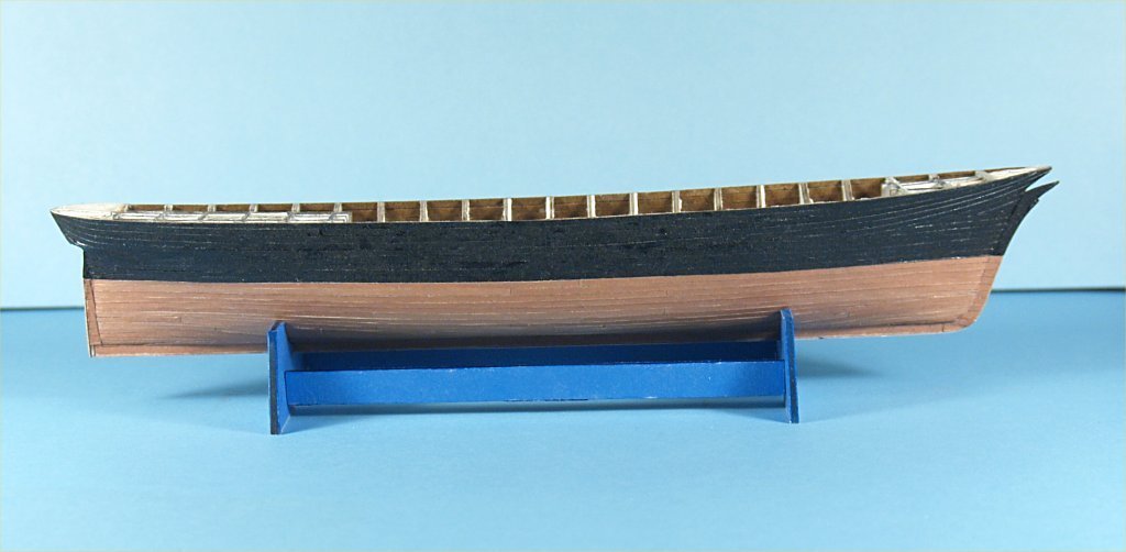
- 28 replies
-
- 10
-
-
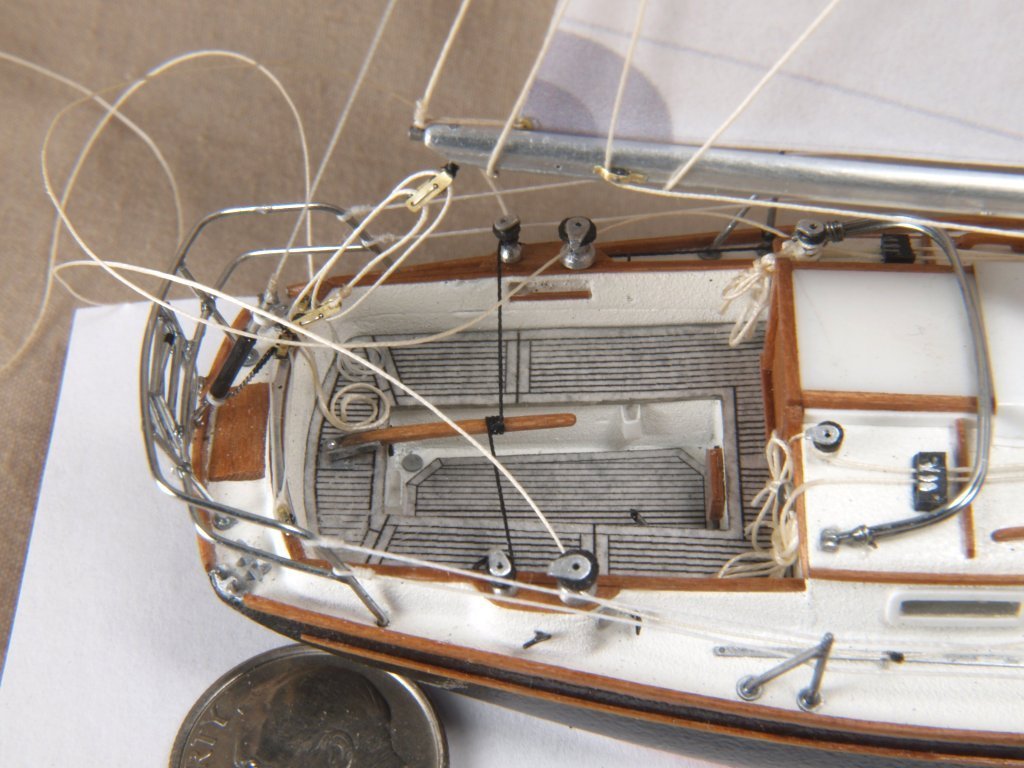
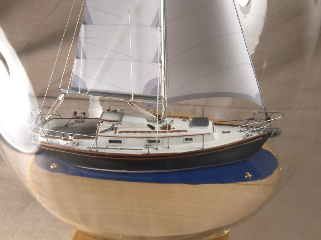
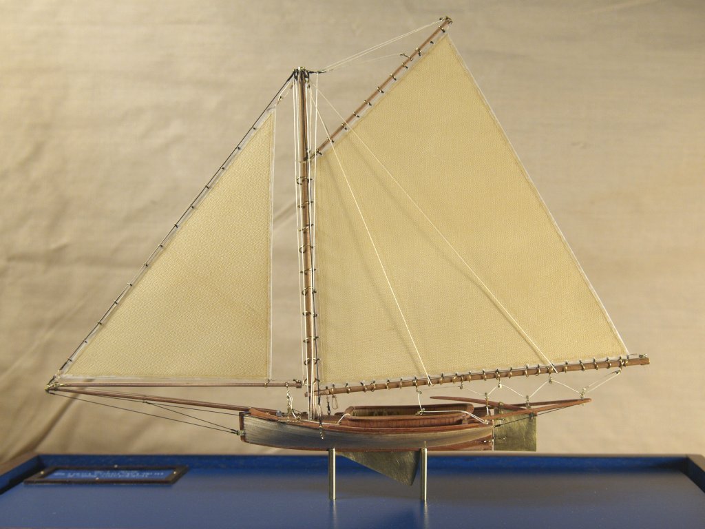
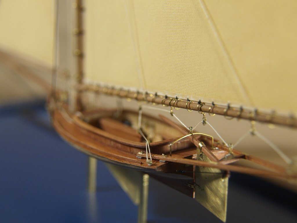
Greetings Tim, You are more than welcome! Glad the info was of some use to you. I've used this style of block making for at least two modern boats. First is the Morris Linda 28 "Shearwater", which was inserted into a street light bulb in pieces and assembled inside, hence the loose rigging lines as they can only be tightened up when the model is completely reassembled. The second is a modern copy of a famous sandbagger that won many races on Lake Geneva in Wisconsin. There is a part of a dime visible in the Shearwater closeup for size comparison. Anchor's A Weigh! John Fox III

-
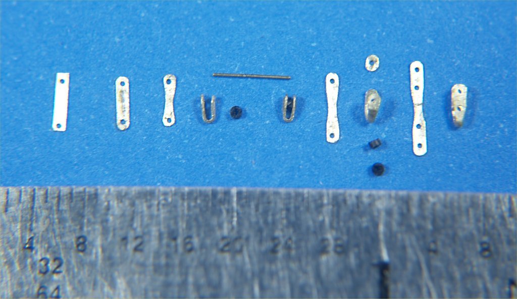
Greetings Tim, Not sure if you could make them small enough for your purposes, but I've made the ones in the photo below quite easily. The metal used was .01 brass, cut as pictured, then filed and sanded into shape. The sheaves of these blocks are small slices the insulation from very fine electrical wire, drilled out to fit a piece of wire. The thicker wire was cut to length, then pushed into the holes in the brass with the sheave in between. A tiny dab of super glue was used to hold them together. Anchor's A Weigh! John Fox III
-
Experiments in Card/Paper Modeling
John Fox III replied to John Fox III's topic in Card and Paper Models
Greetings druxey, Thanks for the kudo! I have been building sub miniature ship in bottle and light bulb models for over 30 years, using solid carved basswood hulls and all wood and styrene parts. The miniature chain method was developed for those models. Anchor's A Weigh! John Fox III -
Experiments in Card/Paper Modeling
John Fox III replied to John Fox III's topic in Card and Paper Models
Greetings Tim, Glad you find the build interesting! It's a bit frustrating learning techniques that work with card stock, lots of attempts at making parts that did not work before finding ways that did work. Anchor's A Weigh! John Fox III