
John Fox III
-
Posts
119 -
Joined
-
Last visited
Content Type
Profiles
Forums
Gallery
Events
Everything posted by John Fox III
-
 Greetings Glen, Thanks! There's a certain level of satisfaction that is hard to beat when I get one right. Anchor's A Weigh! John Fox III
 -
Greetings Mark, Thanks! Glad the model pleases you! Those large light bulbs offer so many possibilities for models. Anchor's A Weigh! John Fox III
-
Greetings Keith, Thanks for the kind words! I like making people's eyes pop out! <Grin> Anchor's A Weigh! John Fox III
-
Greetings, I just finished the log on my Endurance light bulb model, but have no idea how to mark it as "Finished" in the title. Or, does that get done by one of the moderators? Anchor's A Weigh! John Fox III
-
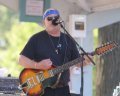
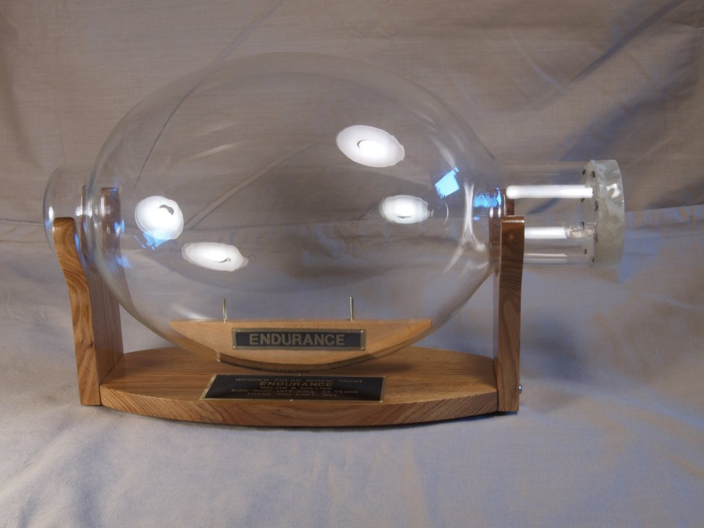
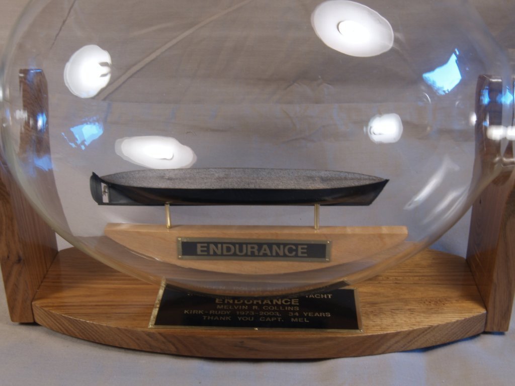
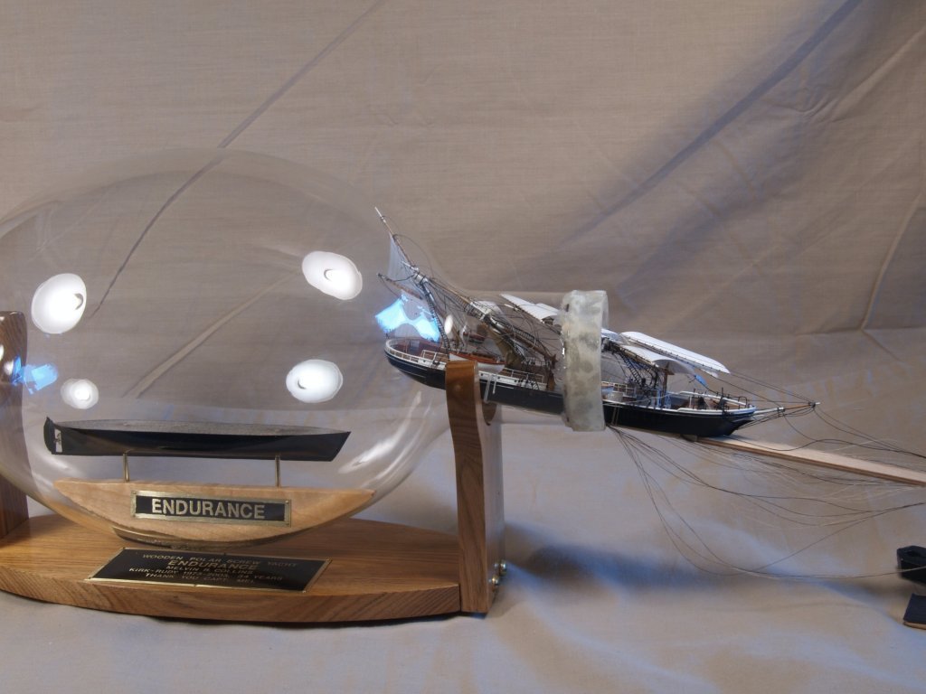
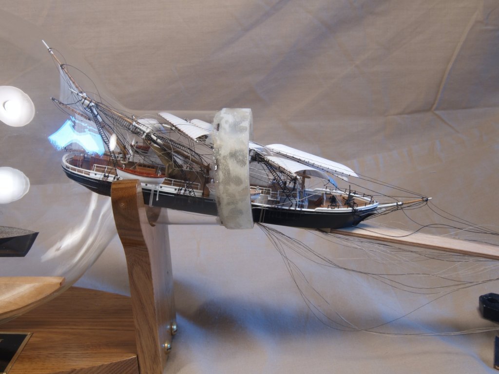
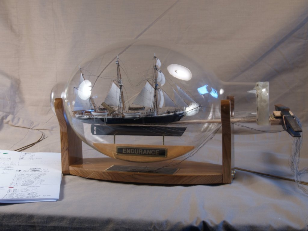
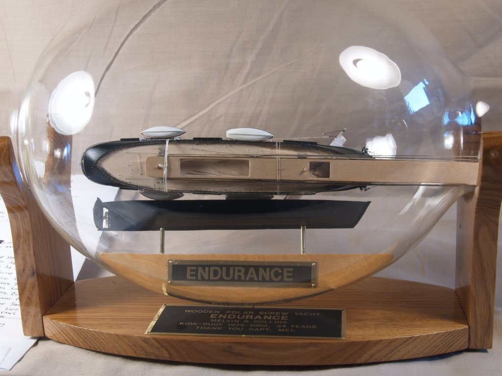
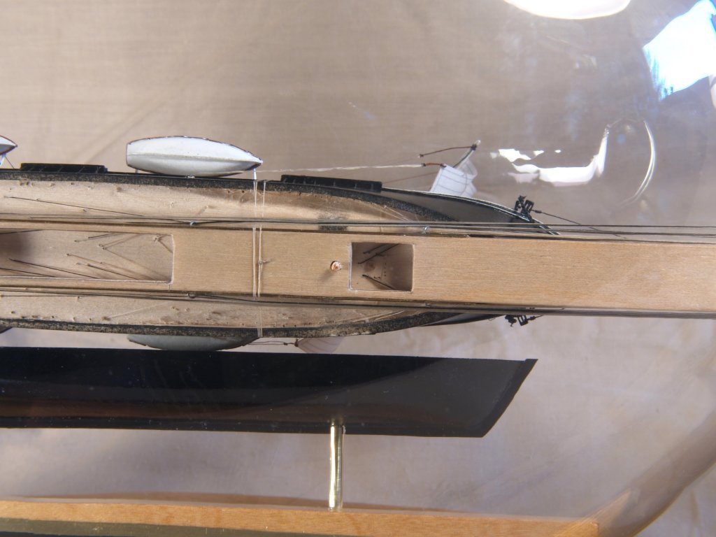
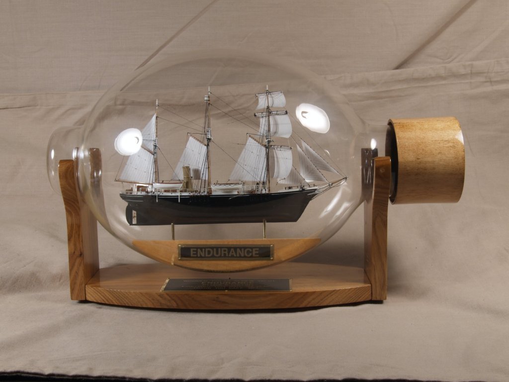
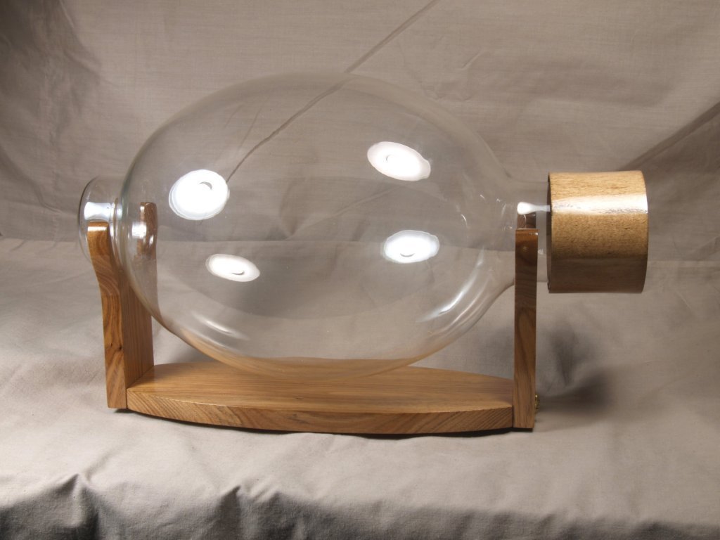
Greetings All, First off, thanks for all the "likes" and "wows"! This is the last of the Endurance log. First off I have a photo of the light bulb ready to use on it's stand. Then I have the lower hull part inserted and glued in place. Finally the model with all the control lines tightened and ready to glue. Next two show the special holder I made to keep the lines straight, and with openings allowing me to put CA glue right on the exit points of the control lines. Next I have the upper hull ready to glue to the lower hull, there are pegs to align it. That is probably the trickiest part of the finishing of the model, need to rest the upper hull at an angle, with the pegs near the holes, and then apply white glue to the holes and push the upper hull down. Lastly I have the completely finished model. Anchor's A Weigh! John Fox III
- 60 replies
-
- 16
-

-

-

-
Greetings Al, Thanks! Not sure about the "always", but I do try! <Grin> Been lurking around here nearly as long as you have, but been posting a bit more lately. Anchor's A Weigh! John Fox III
-
Greetings Glen, Thanks! Part of the reason for the creativity for those parts is having to make many of them. I often built 2 or 3 models when I was building them for sales, so always tried to find ways to make things better/easier. I love the ships/boats of that era, I did a static display model of Amundson's Gjoa a few years back too. Anchor's A Weigh! John Fox III
-
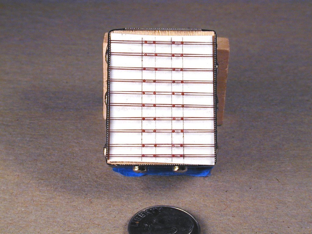
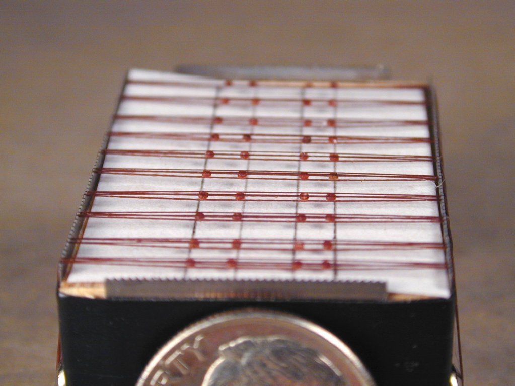
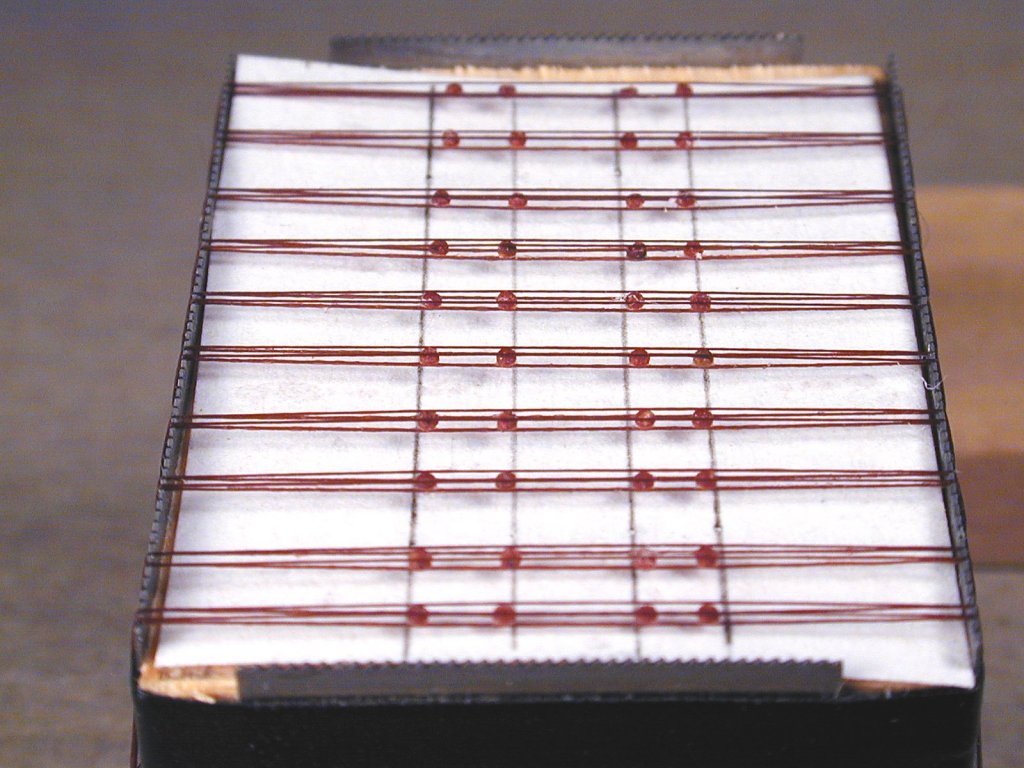
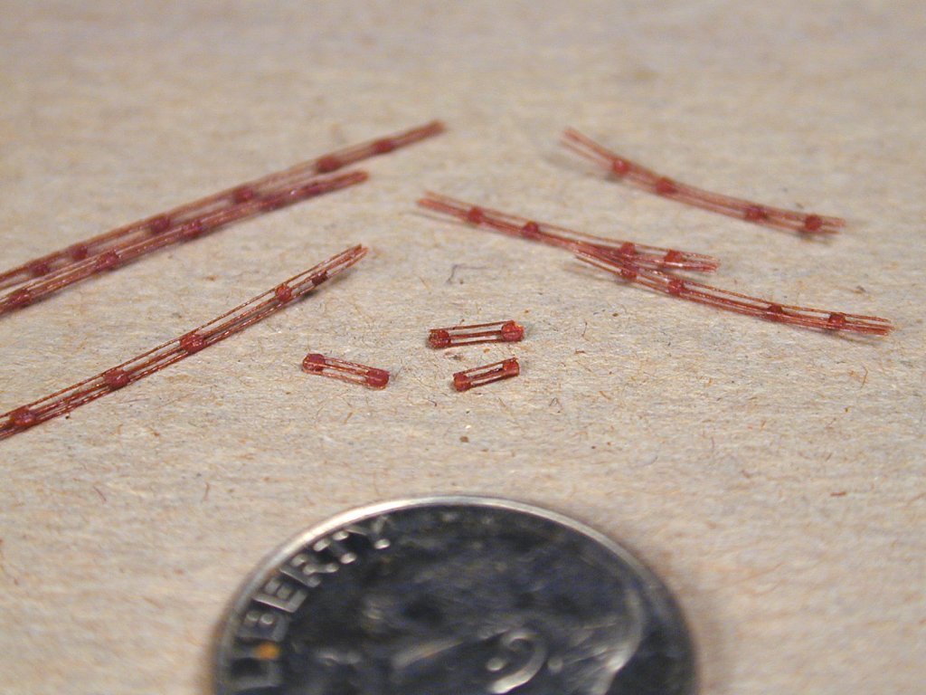
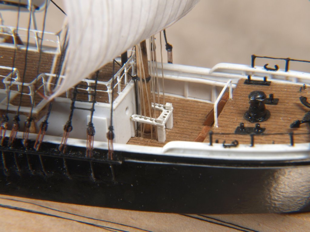
Greetings Keith, Will attach a few photos of how it's done. Wish I had some better ones, but will look around to see if I do. Basically, circular punches are made, shown, in an appropriate dia.. Circles are punched out of stained card stock, or construction paper of the right color, and these are placed on top of threads on a jig, then glued with CA glue. The jig was made from sections of a 71 dpi. razor saw blade, and screwed to a hardwood block. A piece of paper with deadeye spacing lines is slid beneath the threads. The threads were saturated with CA glue before adding the circles. A second layer of threads is rigged in the same tooth gaps, so they are directly over the threads beneath the circles, then glue applied again. The deadeye pairs are then cut from the jig, then trimmed to the outside edges of the deadeyes. If they are large enough, saturated thread pieces can be added between the ones already on the deadeyes, They are surprisingly strong, though it took a while to figure out exactly how much glue to use to make them. I can pull the shrouds quite tightly without them separating, at least most of the time. Anchor's A Weigh! John Fox III
- 60 replies
-
- 10
-
-
-
-
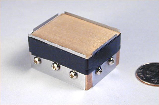
Greetings Roger, Yes, it's a sodium vapor street light bulb. I had a friend who changed them for the city, and got a dozen or so used ones. Opening the bulbs is a bit tricky as the glass is relatively thin. I wrap fine fiberglass cloth around the portion of the "neck" that I wish to cut through, then saturate it with epoxy glue. When fully cured I use a Dremel and thin abrasive cut-off wheel to carefully cut through the glass. Anchor's A Weigh! John Fox III
-
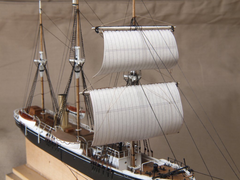
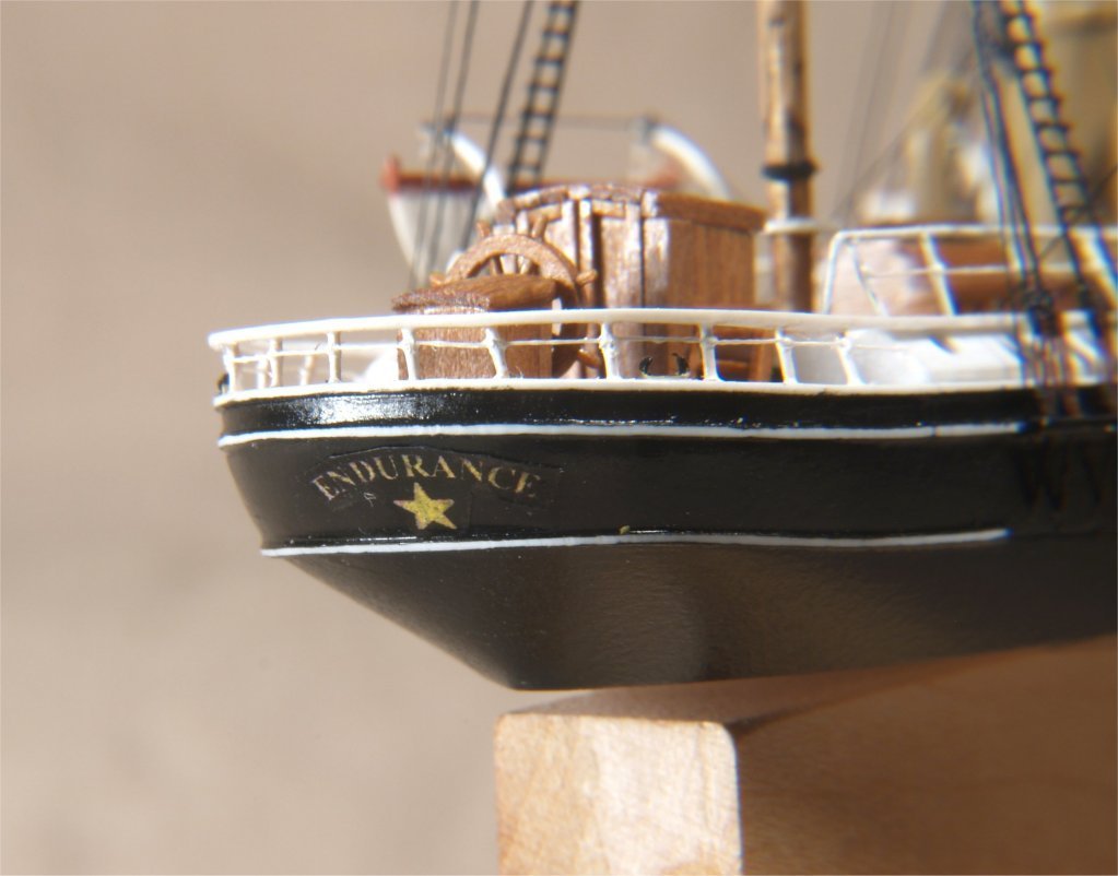
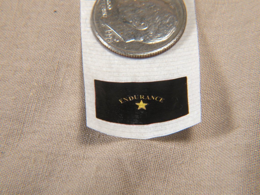
Greetings All, Today I have a few photos to share. Adding sails and the name tag on the stern. Name tag was printed on a cigarette paper, after printing on standard paper then taping with cellophane tape the cigarette paper right on top of it. It was then sealed with thinned varnish, installed with white glue, and a light coat of thinned varnish on top. The sails are printed on thinner printer paper, identical on both sides. The last photo shows all the control rigging lines exiting beneath the upper hull. Anchor's A Weigh! John Fox III
- 60 replies
-
- 15
-
-
-
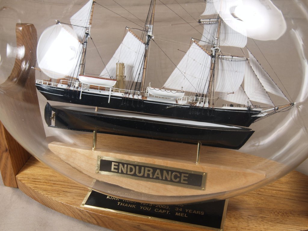
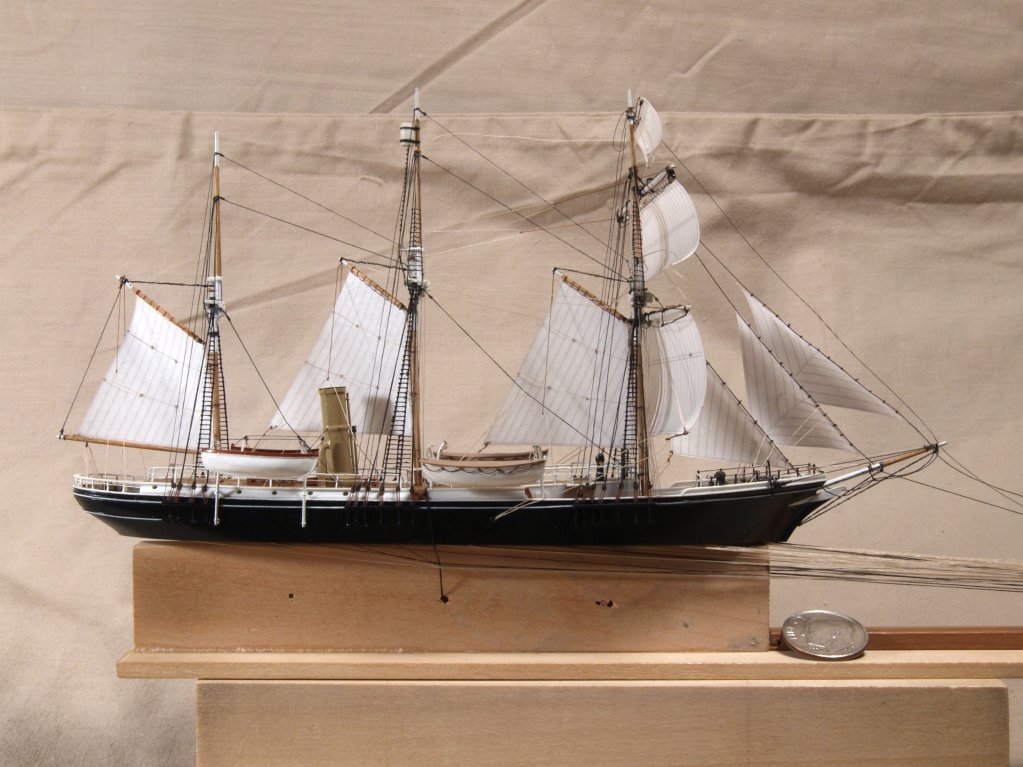
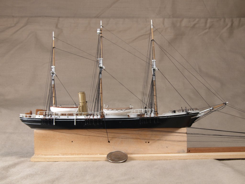
Greetings All, Today I have some more detail photos, plus an overall view of my Endurance model. The last shot is of the standing rigging. All the forestays are "control" rigging lines, i.e. the lines that are pulled from outside the light bulb to raise the masts. These lines exit the hull into the space carved beneath the upper hull. Anchor's A Weigh! John Fox III
- 60 replies
-
- 12
-
-
-
Thanks! Anchor's A Weigh! John Fox III
-
Greetings, Recently updated my profile to add my NRG membership, but it does not show the logo on my previous posts. Does it only work on new postings? Anchor's A Weigh! John Fox III
-
Greetings Pat, Thanks! I really enjoy working out to super detail, and then seeing if I can do it! Anchor's A Weigh! John Fox III
-
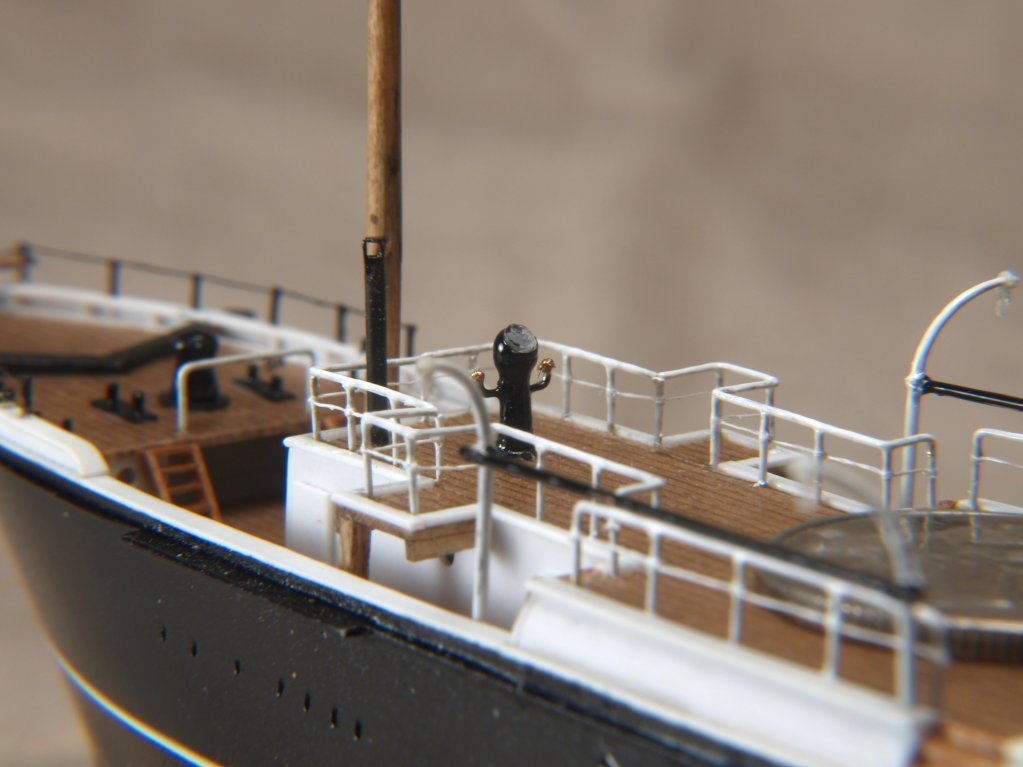
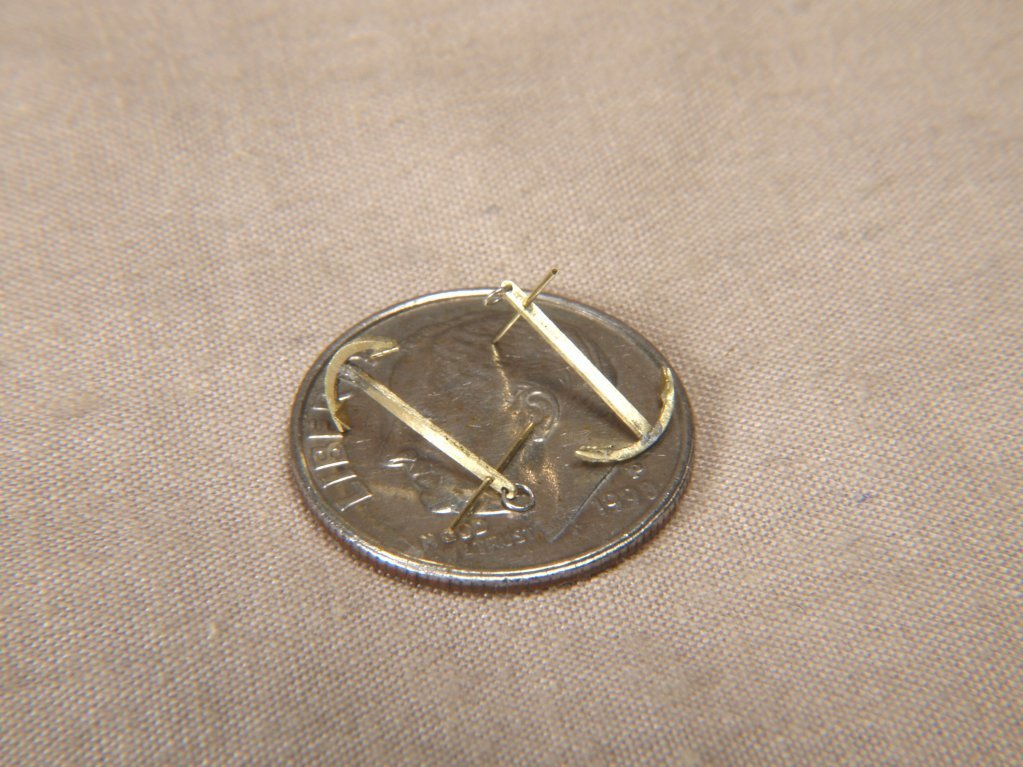
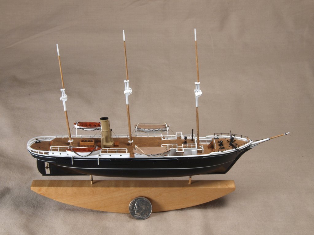
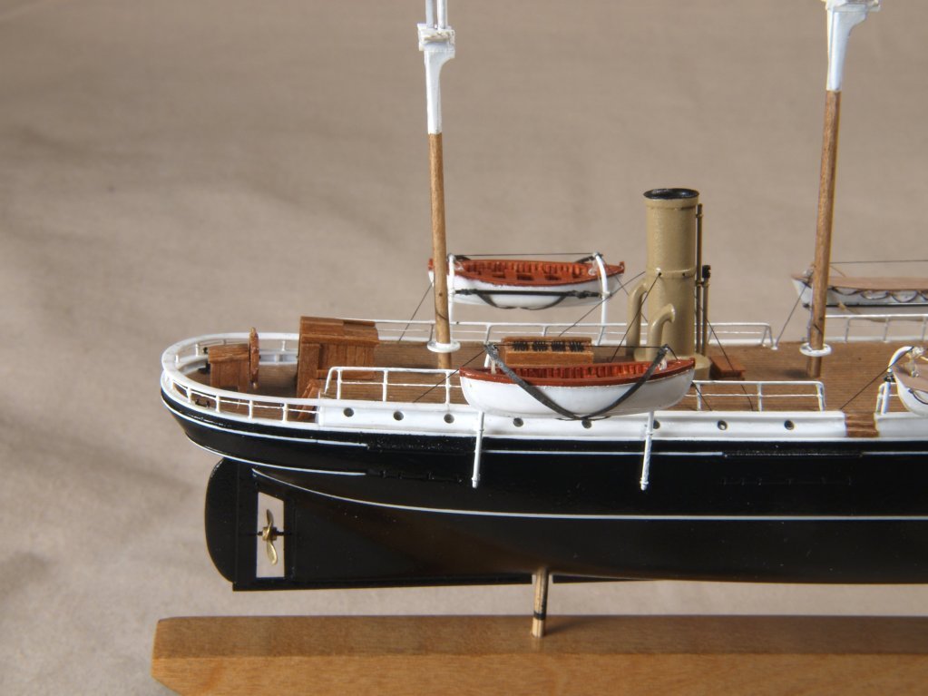
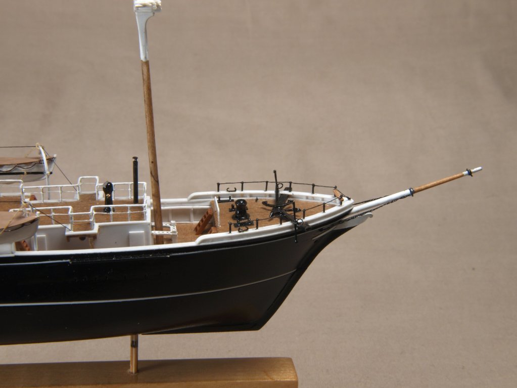
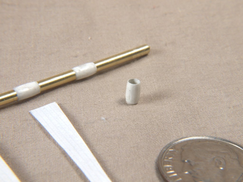
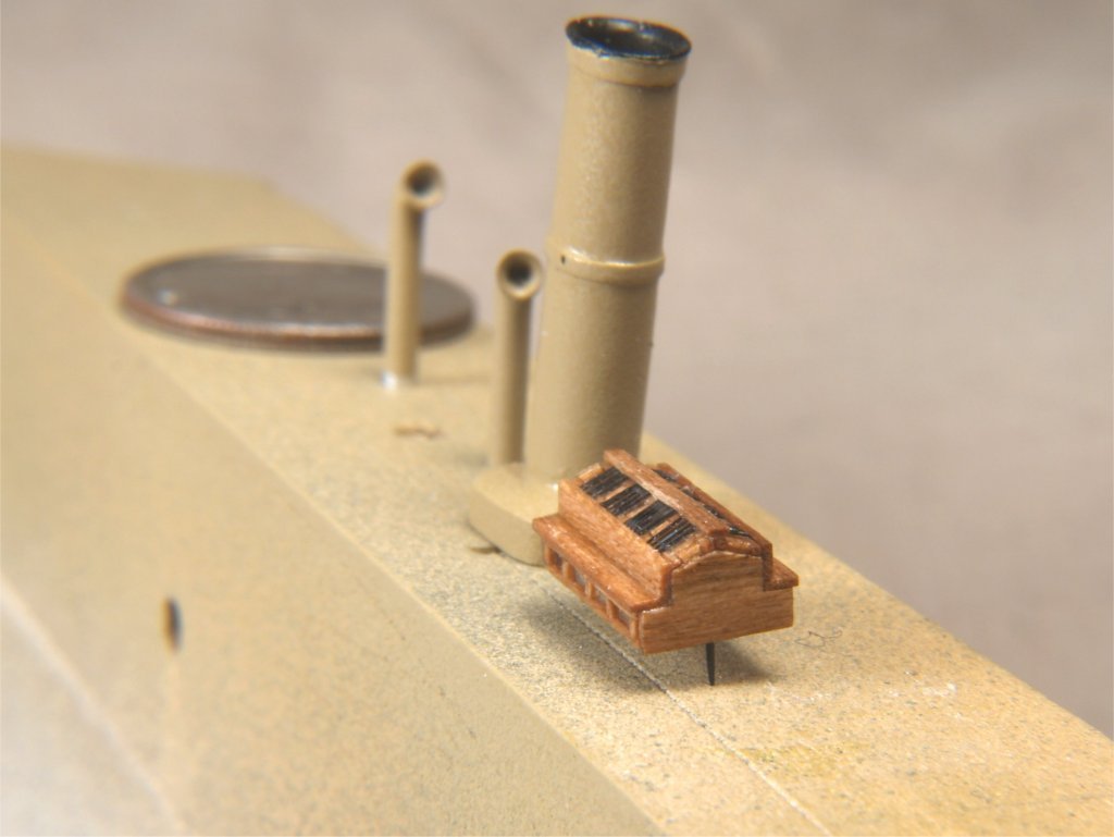
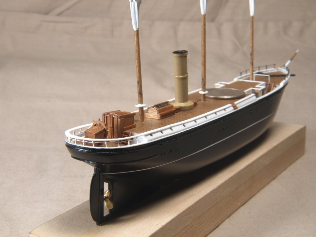
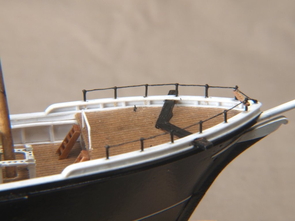
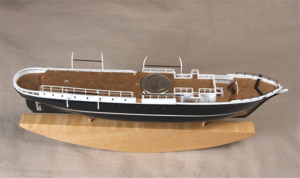
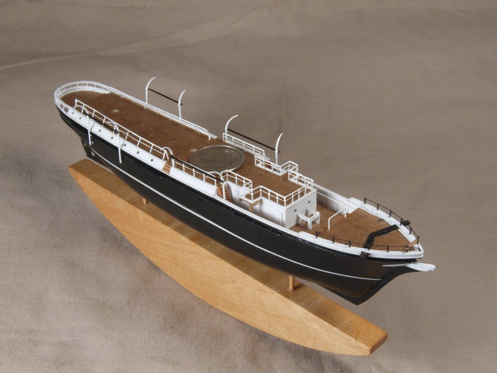
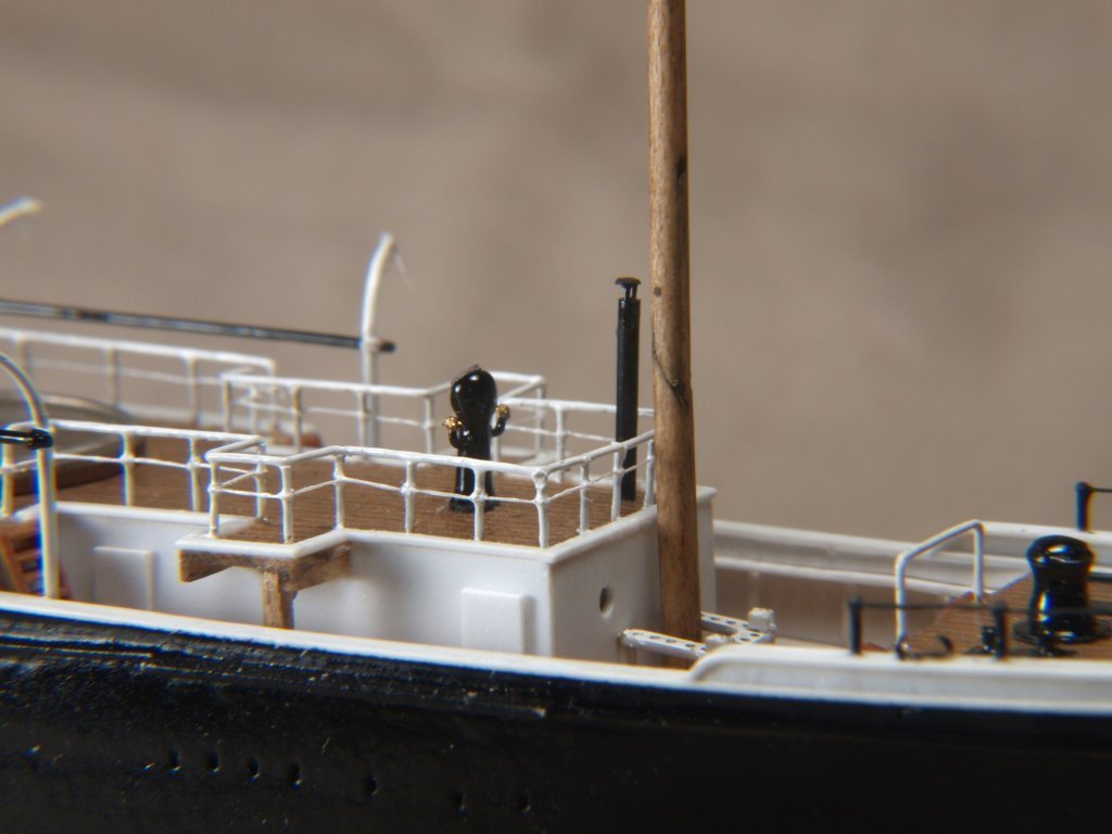
Greetings All, Today I have some more details added to my Endurance model. The observation barrel, made by wrapping paper around a suitably sized brass tube, then sanding and sealing with CA glue. Funnel and ventilators painted and skylight/bench made from wood and thread. A few over view shots of details in place, including wheel and stern railing. Bow area has catheads and ladders, also rails made from wire pins and thread. The rest of the railings were made the same way. Also added the boat davits, made from wire. Lastly the binnacle, smoke stack and capstan. Smoke stack is painted aluminum tube, with thread holding up the top. The binnacle and capstan were my first attempts at using casting and molding, using a kit from MicroMark. Hadn't mentioned before, but the prop was made from brass. Anchor's A Weigh! John Fox III
- 60 replies
-
- 15
-
-
-
Greetings, It is somewhat similar, big difference I see is that the roller spar is above the yard on that one. Anchor's A Weigh! John Fox III
-
A method for making panelled sails using paper
John Fox III replied to Cathead's topic in Masting, rigging and sails
Greetings All, I have another alternative for making paper sails. The photos are pretty much self explanatory. I used X9, 16 lb. printer paper, and thinned white glue. Basically, a whole lot of equally spaced small nails/pins were sunk into a piece of wood, down both sides of the top. A sheet of clear acetate was taped down between the pins, a piece of paper taped on top of that. Then fly tying thread was strung between pins. Thinned white glue was then applied to the paper and threads with a paint brush, a second piece of paper placed on top, and a second acetate sheet on top of that. A second board was placed on top of it all, and clamped down with multiple C clamps. Left to dry for 24 hours, then disassembled and the threads cut. One thing to note is that when applying the glue the thread stretched a bit, and some portions of the resulting sail would not have glued tightly. What I did was to make multiple sheets of sails, and pick out the areas that were the right size and the entire area was glued properly to use for my model. I tried various thread colors, but found that they were too prominent if not using white thread. I did not try different papers, might be worth checking out the method using something other than printer paper. For the some of the jib sails I cut two pieces and used thin paper to glue them together. Anchor's A Weigh! John Fox III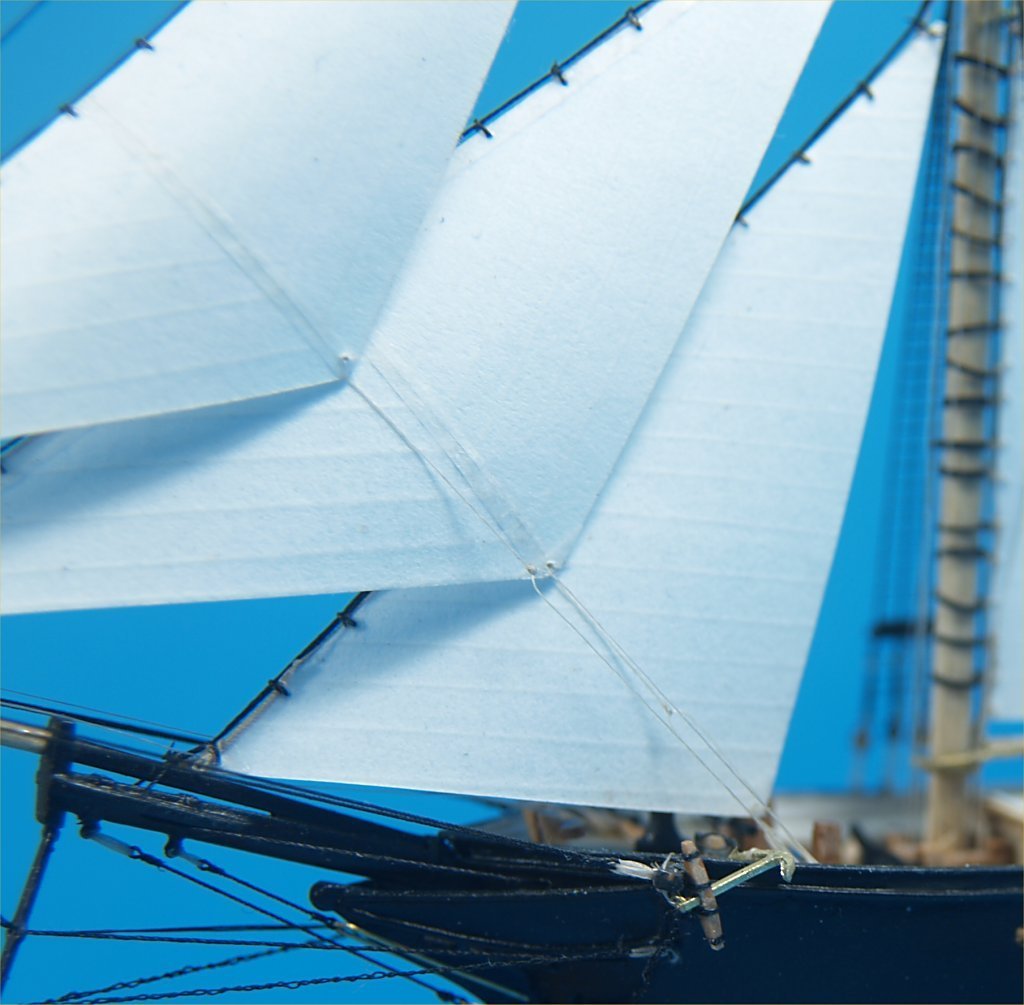
- 49 replies
-
- 11
-
-
- sails
- sail panels
- (and 1 more)
-
Greetings Mike, Thanks for the kudos! Hope it does inspire some thinking and experimenting, that's what all my posts are there for! The hidden hinge is certainly not my original idea, don't know if anyone knows for sure who did think the idea up. I know that for many years it was known as the "Hinkly Hinge", due to the fact that a popular ship in bottle builder with that name used it and wrote about it. I just refined it a bit, by using the multiple veneer layers to make the cutting and carving easier that attempting to make the parts by whittling away at a solid wood dowel. Anchor's A Weigh! John Fox III
-
Greetings Ian, I never actually looked for anything similar quite that modern. Makes sense though, the technology certainly is up to it now days. Anchor's A Weigh! John Fox III
-
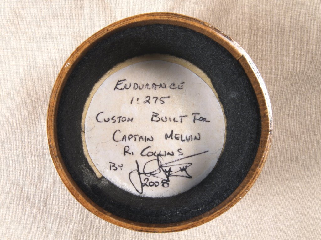
Greetings All, Today I have some more detail work photos to share. The funnel and ventilators were made from aluminum tubing. The funnel was pinched slightly to form the final shape, then the top edge rounded off by pressing a drill bit at 45 degree angle and moving it around the circumference. The ventilator flares were made similarly, then bent to 90 degrees near the top. The yards, booms and gaffs were all made from glued up layers of maple veneer. Interesting to note that the topsail is not attached to the yard, as the other square sails are. Close inspection of the Hurley photos shows that the topsail was actually attached to a second spar, mounted beneath the yard itself. I have never seen this arrangement previously, or since. From photos it would appear that the spar is actually a roller, and the sail is rolled up onto this spar much like a window shade arrangement. I do not think there was a spring inside the spar, as in a shade, but instead when the sail is rolled onto the spar a lines are attached at each end. Thus, when the sheets are hauled to lower the sail, the lines attached to the spar roll up onto the spar. So, when furling the sail the two "reef lines", as I call them, are hauled to cause the spar to rotate and the sail to get wound around the spar. There is an arrangement of a metal device, not clear enough to get exact details in the photos, which appears to extend forward from the yard and spar, an arm of sort through which the reef line runs. This arrangement would replace the normal clew and bunt, leech lines for the topsail. I wonder if it worked properly, or as intended, since I have never seen it replicated. Lastly I have a photo of the light bulb the model will be installed in, along with another of the inside of the cap for the bulb. Anchor's A Weigh! John Fox III
-
Thanks Pat! I guess the moderators left this one out in an isle, as people seem to stumble into it! <Grin> I have actually been accused of having a team of trained spiders to do my rigging work! <Grin> I don't know how impressive it all is, I only hope that by showing what CAN be done, it might encourage others to think out of the box a little, and try things they might think won't work. Anchor's A Weigh! John Fox III
-
Thanks Gary! It took a very long time to figure out how to make ship models as tiny as the watchcase Connie model. The masts and yards were the hardest to make, until I found insect mounting pins. They were steel covered with an enamel coating that was black. There are many sizes, and with a little work, one can even taper the yard pins, and later color them black with magic markers. Anchor's A Weigh! John Fox III
-
There was on the original Polaris, however from Hurley's photos it appears that from the forward cabin to the stern it was completely covered over with decking. I think it was done to keep the lower deck amidships covered to keep in heat. There were many, many changes made as the expedition continued, including adding a covered area over the wheel, with a walking deck completely over the stern area. I did not add the dog sheds, or the walkways over those, which included raising the pin rails on the mizzen, as they were added after leaving South America with the dogs, and I didn't really like the way that all looked later. Anchor's A Weigh! John Fox III
-
Thanks! It doesn't always work out, especially at the bow and stern areas. It does make adding most of the ribs pretty well though. Anchor's A Weigh! John Fox III