nobotch
-
Posts
55 -
Joined
-
Last visited
Content Type
Profiles
Forums
Gallery
Events
Everything posted by nobotch
-
How would you improve your Byrnes tools?
nobotch replied to Keith_W's topic in Modeling tools and Workshop Equipment
Not really. Actually I had asked myself the same question the other way round: any reason I could not or should not use wooden inserts instead of aluminium ones? As I am much more familiar with woodworking than metal working the decision was an easy one. Maybe a metal splitter/anchorage assembly screwed to the insert would be slightly sturdier, but the little bit of additional sturdiness is not necessary. Regarding the wooden inserts: they are as stiff and sturdy as the aluminium ones if you make them of 3mm or thicker birch plywood. This is easy earned money at saving 8$ per insert, especially if you make a batch. I first made one to see how it goes, and then in less than an hour a batch of 10. -
How would you improve your Byrnes tools?
nobotch replied to Keith_W's topic in Modeling tools and Workshop Equipment
It's the first picture in the first post in the thread I linked to. No need to click back to that thread again just for the picture, here it is again: The first one I made of solid mahogany for the plate and thin birch plywood for the splitter. For the next ones (see attached picture) I used 3mm (1/8") birch plywood for the plate which helps to keep the edge near the holes intact. Start by cutting the plate to size, bore and countersink the screw holes before thinning down these borders and before rounding over the corners. As the recess in the table is too thin to receive a stable enough wooden zero clearance plate I used thicker wood (the 3mm ply) and thinned it down where it sits on the aluminium ledge in the table, using the Byrnes saw itself to do so: raise the blade by as much as you need to reduce the plate thickness - there are quite a few cuts to do, start with the innermost ones. Clean up the surfaces with a chisel, knife or scraper. Once the plate fits the recess (it should be perfectly level and drop in nicely without applying any force at all, if it's a bit a loose fit that's fine too) you have to thin down the small zone where the flange would otherwise touch the insert when the blade is all up. Then screw the insert plate in place, align the rip fence over the right edge of the plate so that you will not cut into the fence while now rising the blade with the saw turned on. Now, with the saw unplugged move the fence to the right, remove the four screws and lift the plate slightly with the blade still in the slot you just have cut, and move the fence to the left until it touches the right edge of the insert plate. Secure the fence in this position and replace the wooden insert with the one that came with the saw, then cut open the slot the rear side of the wooden insert. Next, cut out the splitter to the shape it needs to be. Maybe you'd like to first make a cardboard or paper model/template of it to define its shape, it really helps. Don't make the splitter too high because these rather thin splitters would become too flexible over its height. Sand, plane or scrape it to the exact thickness of the kerf your blade makes, screw the insert in place and tack glue the splitter into its correct position it the extended slot. 1mm from the completely raised blade is just fine, don't go too close. When the glue is dry place the insert upside-down into the recess in the table and build up an anchorage around the part of the splitter that will be inside the saw. Be aware of the position of the blade support. When the glue has dried place the insert/splitter in its normal position using the 4 screws, and sand the splitter further down a little bit from each side using a small, square sanding block (240 grit is ok) and a square wooden block to hold against it from the opposite side. In the end the splitter should be about 0.1 - 0.15mm thinner than the saw kerf. I hope I didn't forget anything essential. The whole thing sounds more complicated than it is, but it takes a bit time, patience and 3D imagination to do it.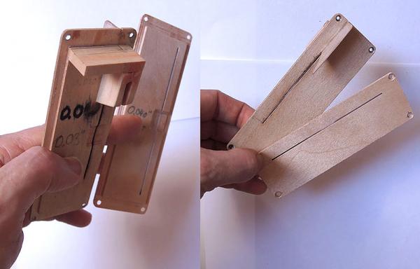
- 62 replies
-
- 13
-

-
How would you improve your Byrnes tools?
nobotch replied to Keith_W's topic in Modeling tools and Workshop Equipment
Some time ago I posted here my own additions and mods I immediately made to the saw after I bought it, and I find them useful, helpful or even necessary every time I use the saw. It takes two screws to remove the fence, which is quick enough for me. What in the pictures may seem to be four other screws are just location pins. A riving knife would be a great thing, but a good one that can quickly be exchanged according to the saw disk used surely would be an expensive solution. I overcame this issue by making my own zero-clearance plates which include a splitter (shown in the thread I linked to above), which works great. Making those plates/splitters involves some precision work but pays off. For ripping I just use two push sticks, one with a notch cut out on one side of its tip so I can hold the work piece down and at the same time against the fence, and the other just plain square to shove the workpiece forward. Edit 2: I use a "short fence" going to less than the middle of the blade, and of course the splitter. This is a quick and easy solution which allowed me to cut dozens of literally meter-long 1mm and 2mm thin strips that turned out to vary considerably less than half a tenth of a millimetre in thickness from end to end. It is important that the square push stick is broad enough to go at least to the blade. It also should be really square as should be the back of the workpiece too. Like this you will be able to shove your stuff straight through the blade without having to reach with a stick between the blade and the fence. For long pieces an outfeed table is essential (mine is also in the thread I linked to in the first line of this post). Edit 1: link fixed -
Is there a better #11 blade handle
nobotch replied to roach101761's topic in Modeling tools and Workshop Equipment
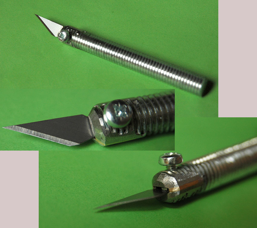
A piece of threaded rod (M12) made a better handle for me. Exactly the right weight and length for my taste.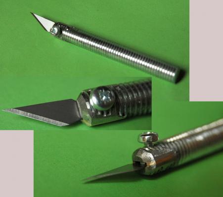
-
Of course they do, why wouldn't they? But there's a catch with the sandpaper method: it is only cheaper if you don't sharpen a lot. Keeping all my plane blades, chisels, gouges and carving knives sharp by using the sandpaper method (aka "scary sharp system") I would spend each year as much for sandpaper as two nice Japanese waterstones cost! Halfways and/or unevenly worn sandpaper does a poor job on sharpening. For "only" sharpening very small blades, and not sharpening many blades several times a week the sandpaper method may be a good option though.
-
May I ask why you only rarely use it? Although I am very happy with the use and results of my sharpening equipment (water stones, diamond plates, guides, truing plates - for that money I almost could have bought the Tormek! LOL) I still would like to know more about the strong and weak points of this WS3000 machine (after all, it "only" costs about the price of another two very nice waterstones or diamond plates, haha).
-
Bill, it looks like you have a very reasonable dustcollection setup. Bigger ducting cross section is goos as long as the blower can keep up delivering a high enough airflow speed in the "fat tubes". I don't think that you can have any overkill at all on dust collection. The big problem with dust is that we only really discover protection is not good enough when it is already too late. Those ambient air filters are a great addition, but they can not replace dust collection right at the machine or even better "at the blade".
-
A well designed cyclone lets about 10% of the smaller than 5 micron sized particles through to the filter. Of course, no dust collection system will deal with the dust it did not capture, regardless if hooking up or not a cyclone between the machinery and the blower / shop vac. This sounds trivial, but picking up the dust right where it has been produced is essential (as close as possible to where the blade tip or sandpaper makes contact with the wood). Since dust collection does not get more efficient than the design of the hood is, there is still o lot of room for improvement there (more openly speaking, it is generally a very poor design. The older, and also the smaller the machine is, the worse the design regarding dust pickup is, Proxxon, Byrnes and similar saws are no exception. Festool claims to have better dust collection but they don't make many (or any) tool really fitted for model making, and I don't know how much better they really are, but they seem to be better designed than other hand held powertools. Also Saw Stop also seems to have done an excellent job there. (I'm not affiliated with any of the mentioned companies). By the way, static discharge igniting dust in a small scale dust collection systems (leave alone a shopvac based system) is one of those dust collection myths (you may want to read this here). And in any case, grounding a PVC pipe is simply not possible, you can put a wire in the tubing but it will have no effect. One real danger of dust ignition though lies in the dust bin, not in the ducting of small scale dust collectors with 6"-ish ducts: when cutting through let's say a nail and the glowing debris lands in the dust bin you'd better not walk away when you believe the job is done. But then again, with small machinery as it gets typically used in model ship building this is very unlikely going to be a point of interest (I don't remember having ever used wood with nails in it when working on small projects).
-
Proxxon Micro MBS 240/E Band Saw Review
nobotch replied to Blue Ensign's topic in Modeling tools and Workshop Equipment
Cheers Mike. I don't know if it makes a difference, but I always have used plain cardboard, not corrugated. However, I'm glad you could achieve some noise reduction with the cardboard fix. I see that you damped the aluminium(?) housing, which certainly is not wrong (I guess you did the same with the door which I believe is made of some kind of plasic). - Markus -
I hook up a self built cyclone separator between the dust/chip prodiuction site and the vacuum. This saves me dust bags (none at all needed) and keeps fine dust filters (if present) from clogging up too quickly. I built my cyclone according to the scaleable plans of Bill Pentz's model (for those interested in building one: it helps a lot to read Bill's build-instructions on his website here and here). Its geometry is well calculated and the cyclone is very effective. But there are also simpler models of separators (less effective, let more fine particles through to the filter), like for example the Thien baffle Matthias Wandel shows here. I took this picture of my cyclone a few years ago. Now the cyclone and the shop vac sit on a plywood board with 4 small swiveling wheels

-
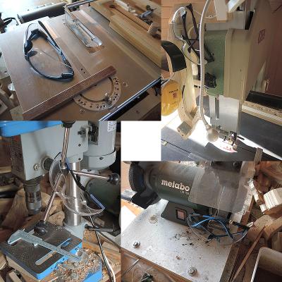
I couldn't agree more. A friend of mine had a near miss using his accu drill. This, and the fact that it bothered me to always had to make two or three steps to grab my goggles when working with another tool were the driving factors for me to do a relatively cheap but very effective upgrade: every stationary powertool has now "its own" goggles, strategically placed in a way that I can't use the tool without moving the goggles "out of the way - onto my nose". I got used to this system very quickly and shed live is now much easier (and a fair bit safer). When using an electric hand drill or a hand powered handdrill with very thin drill bits I reach for the goggles of the next powertool and put them back to their place when done.
-
Proxxon Micro MBS 240/E Band Saw Review
nobotch replied to Blue Ensign's topic in Modeling tools and Workshop Equipment
Hi Mike, I don't have the Proxxon bandsaw, but I have reduced noise on quite a few machines (computers, drill press, cheap scroll saw, and some others) by gluing cardboard sheets (as big as possible) to the inside of the housing or housing parts that act as a resonator. You need the dense variety of cardboard, and it should be thick or you can use two layers if possible. The additional mass of the cardboard is important because it reduces the "vibrational mobility" of the resonator. I normally use epoxy glue on metal and plastic parts. Of course it is also important that the saw's door is firmly closed, without any play. Reading your post you apparently already have hunted down the latter issue, but maybe you still can improve on that one. Cheers, Markus -
Byrnes Table Saw Rip Capacity
nobotch replied to Stefonroman's topic in Modeling tools and Workshop Equipment
Gaetan, The assumption that security had to do with experience is not correct. History proves that experience and "paying attention all the time" does not completely [edit: not even approximately] prevent accidents. Normally they don't happen, even if we make mistakes! But acidentally they do happen, which is why accidents are called accidents. We all make mistakes, also the experienced ones. Also, these small tablesaws have more than enough power to cause serious damage to one or several fingers in a blink of an eye. Even if not cutting off a finger completely (which would be perfectly possible though), an emergency room visit to get done a few stiches will cost consideravbly more than a grade-up to a broader table on the Jim saw, and also would not justify the 30 seconds it takes to remove the fence completely. And by the way, tilting up the fence does not increase rip capability, which is the subject of this thread... However, for crosscutting a crosscut sled is unsurpassed, and you even can leave the original Bryrnes saw guard on when using a well designed sled. Of course you can use your tools the way you want, but if you recommend unsafe procedures you have to accept that someone may show up to correct your statement in order others will become aware of the dodgyness of the procedure in question. - Markus -
Byrnes Table Saw Rip Capacity
nobotch replied to Stefonroman's topic in Modeling tools and Workshop Equipment
Which requires to remove the guard. Not recommendable! -
Byrnes Table Saw Rip Capacity
nobotch replied to Stefonroman's topic in Modeling tools and Workshop Equipment
Hi Stefon, Good question! The maximum distance between the blade and the rip fence is about 97 mm (with no micrometer mounted). If this is not enough for your purposes you can ask Jim to make you one with a broader table to your specifications, for example like this one the amazing and charming team of Beatty Robotics uses. Cheers, Markus -
The Byrnes Saw "inside and around"
nobotch replied to nobotch's topic in Modeling tools and Workshop Equipment
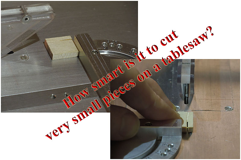
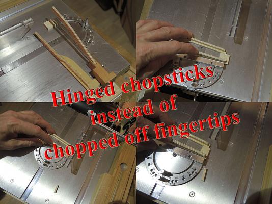
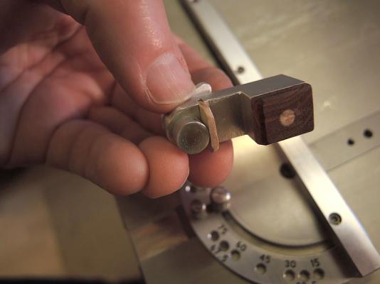
Maybe the following is more useful for most of you than precision measurments on a precision saw. Of course, it is not confined to the Byrnes saw, hence a bit off-topic. I usuallyy cut such tiny pieces using a chisel (a mirror sheen on its flat side makes cutting 90° and 45° angles really easy). But when the Byrnes saw is already on the bench and in use it is very tempting doing such cuts with the new toy... Hence, using "hinged chopsticks" instead of chopping off a fingertip may be a good idea (you may want to click on the pictures to enlarge). Or simply use a chisel. Cheers, Markus
-
The Byrnes Saw "inside and around"
nobotch replied to nobotch's topic in Modeling tools and Workshop Equipment
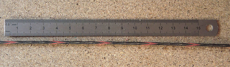
Hi Steve, I am not trying to find a fault, but everything in mechanical industry is machined to tolerances, not to "perfection". This is because perfection is a term in relativity. Knowing the magnitude of the tolerances the Byrnes saw is made to may or may not be in your interest, but it is in mine, and probably in other's too. Even if Jud's reply to your post (curiosity is part of my motivation to measure tolerances) is spot on with part of my answer. Inquiring minds want to know, and without this attitude (which is very typical to manhood) we most probably still would shave with a sharp stone which would be prefectly possible as an avid "youtuber" shows here. But for me, there is more to it. As Jeff from Hobbymill states here it is necessary to use a 0.040" blade for doing precise cuts on stock thicker than 4.5 mm. Now I want to cut 6.5 mm and I would love to use a 0.020" blade to cut evenly thin strips of 1.0 mm, one meter long. Yes, I want to push the limits. Needless to say that this is hardly achieveable by feeding the stock manually, but that will be a task which requires to know the variables, one of them being manufacturing tolerance of parallelism of the blade, another one being stock feed rate, and so on, you get the picture. Now you may ask why I would want to cut such long strips to this accuracy, and you would be correct assuming that it will not be for planking, and maybe not even for ship modelling. I need this accuracy for making herringbone pattern strips used in musical instrument building (see attached picture). When making herringbone strips accuracy is critical for several reasons, one being that an error in thickness will double and a strip sitting in a groove that is 0.2 mm wider than the strip will be plain ugly hence unacceptable. If the saw blade can not constantly "eat away" the error as stock is fed there will be an error of 0.1 mm over the length of a guitar side and this strip would be ready to be binned. Up to now I have thicknessed the strips like it has been done ages ago, using a handplane. But this method takes a high toll regarding waste (shavings) produced. Using a precision saw (0.040" blade) instead of thicknessing strips with a handplane or a thickness sander reduces waste by about 50%. If I can use a 0.020" blade instead of a 0.040" blade I can reduce waste by another 50% (when cutting 1 mm strips for 2 mm herringbones) which would be great because the material to be cut is not just wood but rather a laborious glue-up of many veneers (similar to plywood, obliquely cut and again glued together). So waste is an issue. I'm sorry that the driving force behind my tolerance measurments is not directly shipmodel related, but all this is really not a question about how many angels can dance on the head of of a pin.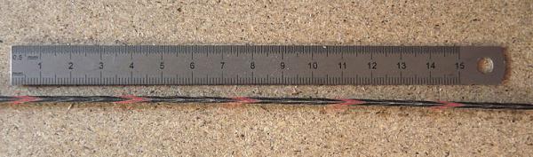
-
The Byrnes Saw "inside and around"
nobotch replied to nobotch's topic in Modeling tools and Workshop Equipment
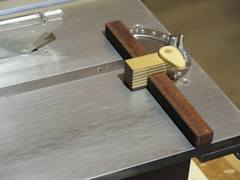
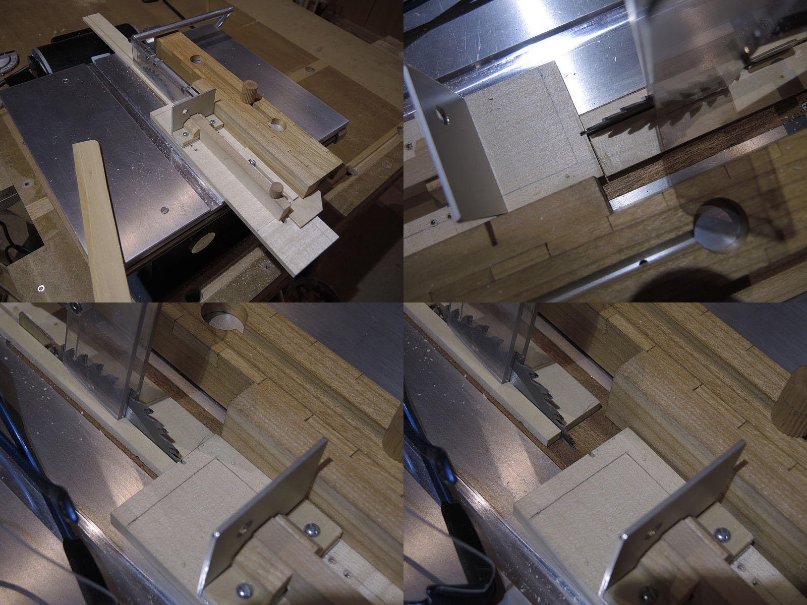
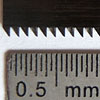
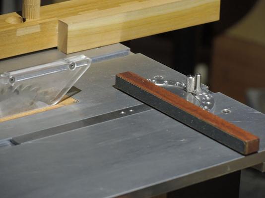
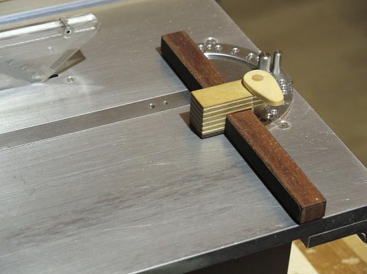
It's nothing new that the Byrnes saw is ready to use out of the box, ready to do precision cuts. No doubt about that, and I honestly have to say that I was as impressed as many other before me were. And yet, I wanted to know how precise it is. "Very precise" is one thing, and attaching some numbers that describe the precision is another one. So I thought I would use the classical approach for measuring parallelism between the blade and the miter slots (measure the distance of the same blade tooth at the same height above the table at the rear (rising) and front position, see first attached picture). Well, this is easier said than done because it turned out that the measuring device by itself interferes, so that I made as many measurements until a clear majority of the results coincided. The numbers I got are approximately 0.0075 millimeters (that is 3/4 of 1/100 mm) deviation over a distance of 60 mm, which is the same as 0.125 mm (1.25 tenth) over 1 meter, which translates to an angle of 0.0072° off perfectly parallel. I find it pretty hard to imagine such a shallow angle, and I can't help thinking that this "error" has very few if any impact at all on real cutting action when using the saw. For example, any slightly uneven pressure from the push sticks will create an error that is easily about ten times bigger than the blade alignment tolerance I have measured. In the following pictures you can further see my newest addition to the saw, which is a sandpaper lined wooden frame that pops into precise position over the miter extension, which helps to avoid that the work piece moves while (or before) being cut. Of course I could have glued the sandpaper directly onto the miter extension, but sometimes it may be necessary to lay a finished surface against the miter extension and in this case having the latter one lined with sandpaper would be less than ideal. Of course I also made a length stop which fits the "sandpaper-frame". Thanks for reading and watching. - Markus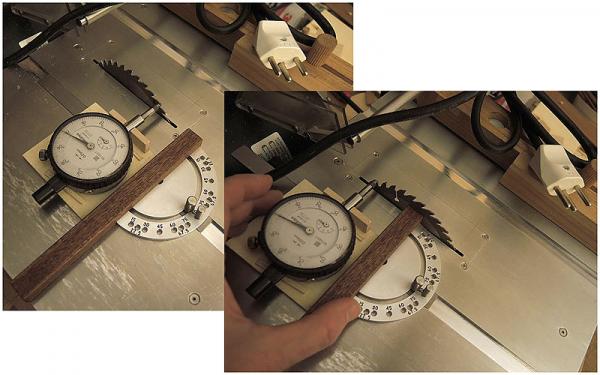
-
Hello Mike, Thank you for your detailed and valuable input, it looks like the combination of dust extraction through the box below with your planned hood halfway around the drum may provide a close to perfect solution. I have seen (on pictures only) such dust exracion shells around a drill press sanding drum, but the hose was attached above the table which I imagine is a bit awkward to work with, so I never persued further the idea of a drill press sander. Yes, being disconnected is a luxury these days, I'm glad you enjoyed it! - Markus
-
Anthony, these are some sturdy looking sanding drums at a very reasonable price. Thanks for the link. Mike, I am most curious about how good dust extraction through that box is. It looks very neat, but I'm a bit skeptical about its efficiency, especially when the piece to be sanded is taller than just a few millimeters I'm afraid that most of the dust will not make its way to the vacuum. I hope I'm wrong though. Please let us know. Cheers, Markus
-
The Byrnes Saw "inside and around"
nobotch replied to nobotch's topic in Modeling tools and Workshop Equipment
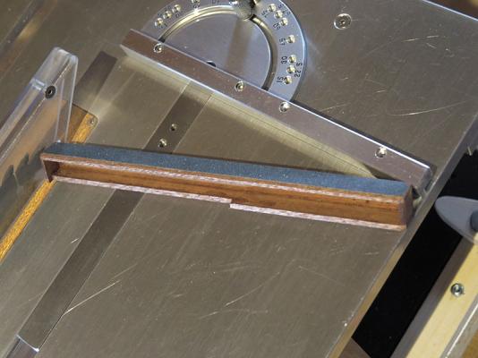
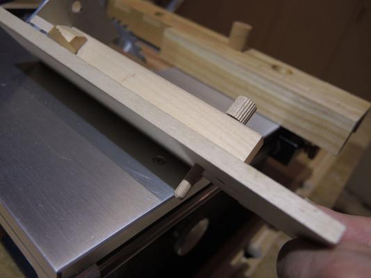
Length stop for the miter gage. The cam clamp mechanism in the second picture fixes it to the miter extension. Cheers, Markus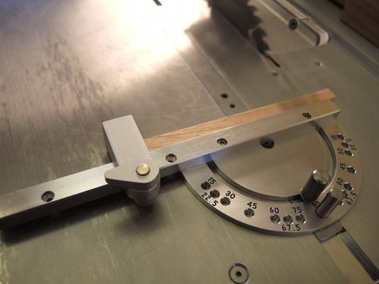
-
The Byrnes Saw "inside and around"
nobotch replied to nobotch's topic in Modeling tools and Workshop Equipment
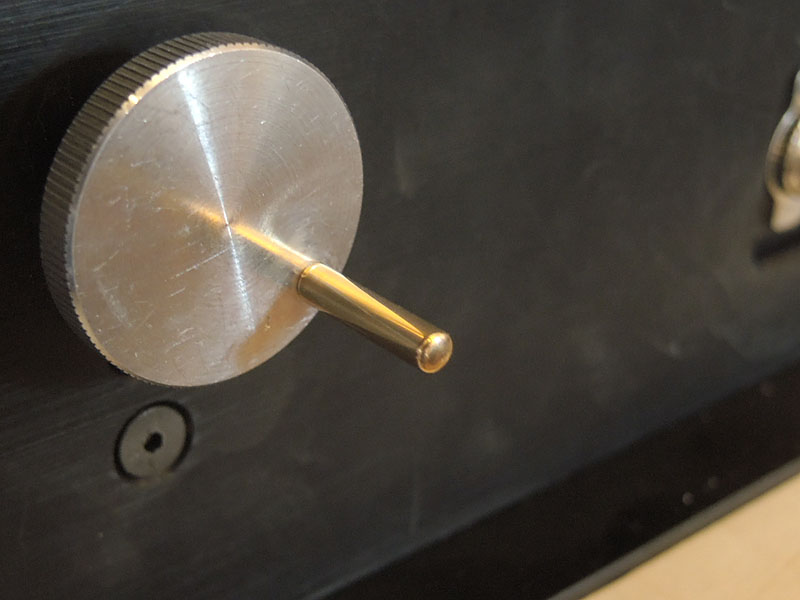
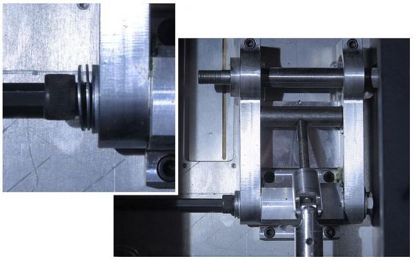
Well Tim, convincing one's wife of the eminent importance of a less than cheap tool we "need" is normally not a mission impossible, but certainly easier to achieve if embedded into a generic long-term endeavor regarding tool-and-toy acquisitions. While getting familiar with THE saw, I noted that when adjusting blade height for non cut-through tasks it lowered by almost 1 mm when locking it in with the long Allen key. It turned out that the underside of the Allen screw head scratches and therefor catches the washer between the screw and the aluminum bar the blade (its axle and bearing, that is) is mounted on. So I added two thin washers with the smooth and burr-less faces against each other. Even if this unwanted movement when tightening the screw is not completely eliminated, it is now at least limited to about 0.1 mm (0.004") after rising the blade (tightening the locking screw after lowering the blade will always add quite a bit due to the play of the adjusting threaded rod to this difference, which is normal). I left the original thick washer in place because my smooth washers are somewhat too thin that I would feel sure they protect enough the aluminum part. Then there is my latest small addition which makes it a bit easier to raise or lower the blade by more than just a bit. I added a brass crank to the adjusting knob. It is screwed into a threaded hole I tapped in the knob, and secured by a bit of epoxy on the threads and a counter nut. I really don't want to get it loose because the threads in the aluminum know would be shredded quickly I guess. Cheers, Markus
-
The Byrnes Saw "inside and around"
nobotch replied to nobotch's topic in Modeling tools and Workshop Equipment
Baseplate and outfeed table: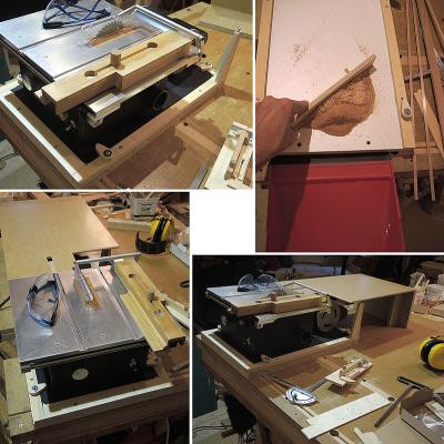
-
The Byrnes Saw "inside and around"
nobotch replied to nobotch's topic in Modeling tools and Workshop Equipment
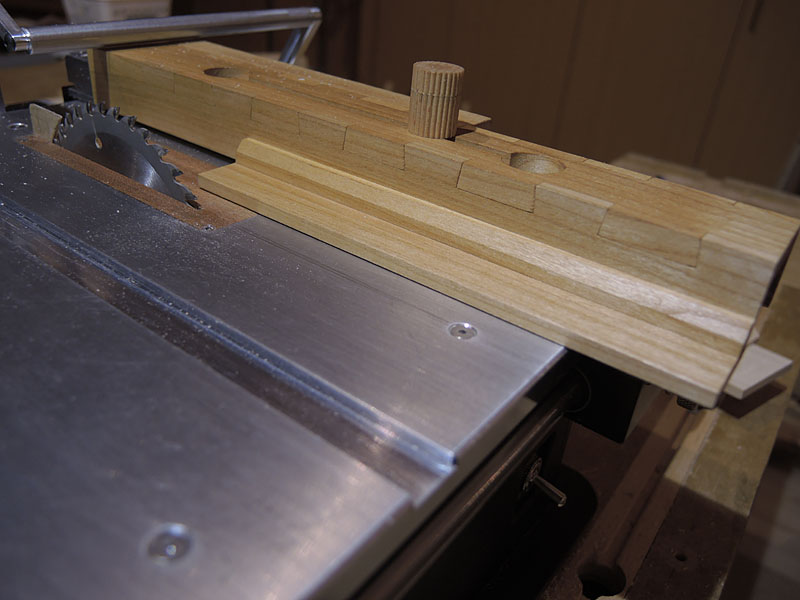
Well, it took a bit longer than just some hours on last weekend. Short fence, high and low profile: Switch from high to low, and to the left the dedicated push stick: The handle assembly screwed to the push stick has an protruding rear pin which prevents the handle from being run into the blade: The push stick (or maybe I'd better call it push board) has a squared front edge, and the piece of wood to be ripped is supposed to be narrower than the push board and to have a squared rear edge. With this, when sliding the push stick along the fence the tendency of the ripped pieces rotate once the lateral push stick is released (shortly before the cut is completed) gets minimized or even eliminated, so that also the las millimeters of the cut should be perfectly accurate. Here some details of the fence and push board, after a completed cut: The next item on my to-do list is an out-feed table. Thanks for watching. Cheers, Markus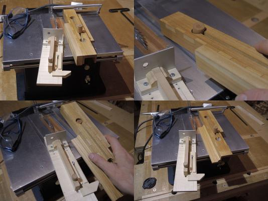


-
The Byrnes Saw "inside and around"
nobotch replied to nobotch's topic in Modeling tools and Workshop Equipment
Michael, that's why riving knifes are such a great invention: they don't get in the way when doing rabbets or when tilting the blade. Cheers, Markus