John Garnish
-
Posts
84 -
Joined
-
Last visited
Content Type
Profiles
Forums
Gallery
Events
Everything posted by John Garnish
-
 In Jean Boudriot's book "The Seventy-Four Gun Ship", he draws a distinction between the bends used on the main anchor cables for a large ship, and those on 'cablets' - lighter cables used for stream anchors. He says "These small cables are differentiated only by their size, and indeed the cablet of a ship-of-the-line may serve as the cable of a sloop-of war". He shows the following anchor bend for a cablet For the larger cables, he shows a simpler "clinch", more suited to the greater diameter and stiffness of the cable.
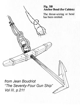
-
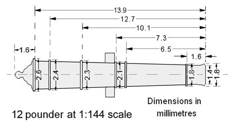
There was not a direct relationship between bore and length, because there were several different patterns. However, you won't go far wrong if you follow Harold Hahn's data from "Ships of the American Revolution and their Models". A copy of the relevant page is attached, with a spreadsheet that I generated from it. cannon dimensions.pdf Best of luck.
-
Ron, Good point. I guess we'll never know. In any case, it lets me off the hook! John
- 30 replies
-
- 3
-

-
- philadelphia
- diorama
- (and 3 more)
-
Chuck, I certainly don't disagree with your and Joel's assessment of the situation during the battle. In fact, they would almost certainly have had anchors out fore and aft, and probably with a spring on the cable to be able to aim the bow gun. However, it seems that Philadelphia sank relatively slowly ("...an hour after the engagement was over"), so there was time for Washington to come alongside - and for both vessels to assume a more seamanlike position for the transfer. This could well have included abandoning the stern anchor(s) and allowing her to swing head to wind. It would be good if someone could track down a full report of the 1935 recovery to see whether it mentions the orientation of the wreck. There should be a report in the United States Naval Institute Proceedings LXII (1936), but I can't get the search engine to play ball. John
- 30 replies
-
- 3
-
-
- philadelphia
- diorama
- (and 3 more)
-
Joel / Chuck Thanks for the comments, with which I agree. However, Philadelphia didn't actually sink until after nightfall (".....about an hour after the engagement was over."), so there would have been time for both vessels to manoeuvre into a more practicable position. Even if Philadelphia had remained at a single anchor (and Col. Haaglund's report mentions only bow anchors), she would naturally have swung head to wind. I still maintain that the transfer would have been very difficult to effect with the wind aft. The question would have been settled if I knew in which direction the wreck was facing, but I can find no reference to this in those parts of Col Hagglund's reports that I have been able to find. Still, I'd be happy to be proved wrong! John
- 30 replies
-
- 2
-
-
- philadelphia
- diorama
- (and 3 more)
-
Sorry, Chuck. It is a bit confusing. It's actually the edge of the diorama base and my kitchen worktop! John
- 30 replies
-
- 3
-
-
- philadelphia
- diorama
- (and 3 more)
-
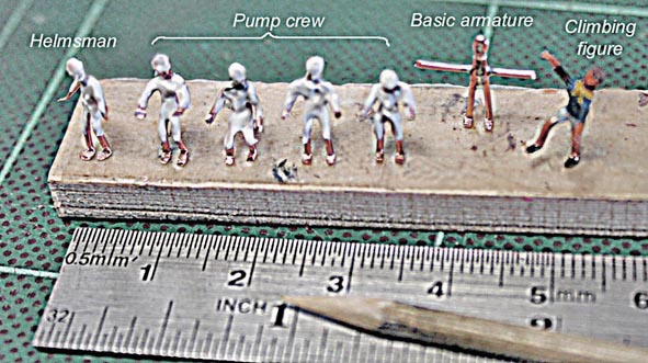
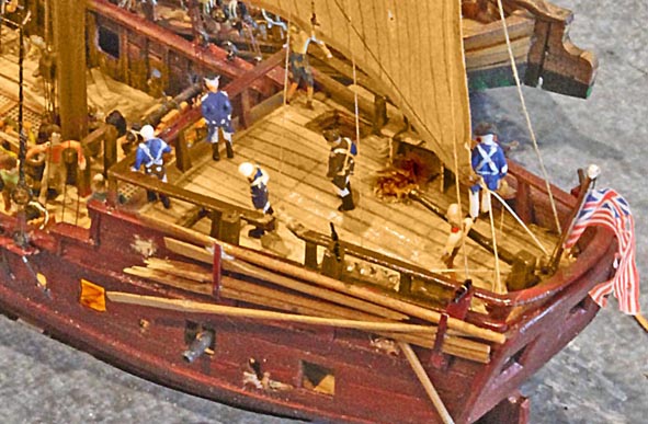
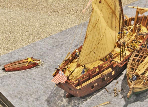
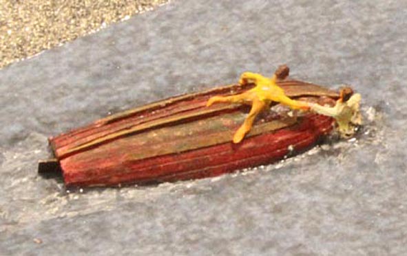
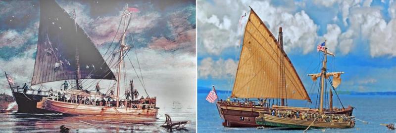
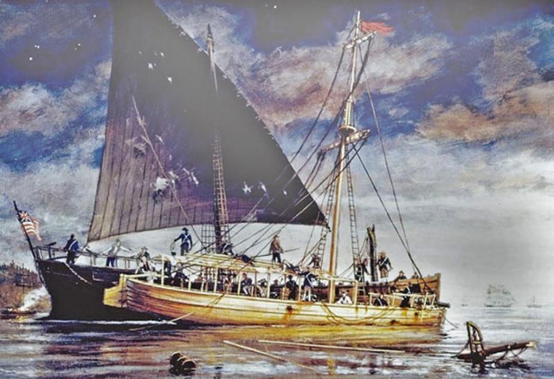
Crew figures At the time of the battle, Philadelphia’s crew numbered 43, while Washington had a complement of 80. I couldn’t see how to fit that many figures on the model – nor, to be honest, did I fancy having to make them. I wanted to convey the idea of purposeful urgency, not rush-hour travel. In the end, I fitted some 35-40 figures to the model. I based the figures around an armature of 0.91mm copper wire (0.036”, 20 SWG, 19 AWG). Head, trunk and legs were formed as a V, with the apex pinched together, with a soldered cross member. The ends of the V were flattened and bent up to form feet, and the armature bent to a shape appropriate for the activity intended. I filled out the figure shape with dabs of Windsor & Newton “Galeria” heavy modelling paste, applied with the tip of a cocktail stick. Once dry, the paste could be shaped further with a scalpel blade and then painted with acrylics. Sails and flags Sails were made from lightweight copy paper (30 gm/sq.m - almost obsolete nowadays), dyed with cold tea. The seams and reef points were simulated by pencil lines. I used an inkjet printer to print the flags onto cigarette paper, taped to ordinary paper in order to feed it through the printer. Once printed, with cigarette paper it is impossible to tell on which side the printing was actually carried out. Diorama For the base, I used a piece of 6mm foam-cored board, 26mm x 18mm, covered by a sheet of heavy textured water colour paper. After cutting suitable recesses to take the hulls, I sprayed this base with water-colour paint in various shades of blue, grey and green. When dry, I then stippled on a layer of Windsor & Newton “Galeria” acrylic heavy structure gel, again tinted with greys and blues, to simulate the lake surface. After fitting the hulls into place, I added more figures as well as various pieces of floating debris, and touched in hints of water flow, etc., around them. As one corner of the base seemed a bit deserted, I added a flight of fancy in the form of a separate small rescue drama. The photo below shows a comparison between the Haas painting and the finished diorama. I took one liberty in replicating this scene. I cannot believe that anyone would undertake an operation like this with the wind aft, as shown in the painting, so the model shows both vessels head to wind.
- 30 replies
-
- 10
-
-
- philadelphia
- diorama
- (and 3 more)
-
Thanks, Druxey. It would have been almost impossible without the digital readout. John
- 30 replies
-
- 2
-
-
- philadelphia
- diorama
- (and 3 more)
-
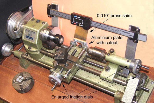
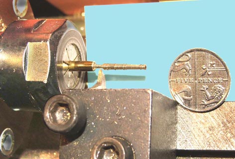
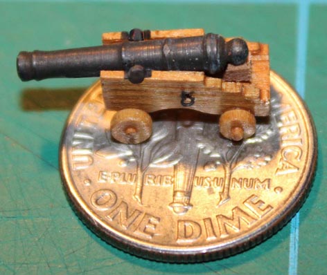
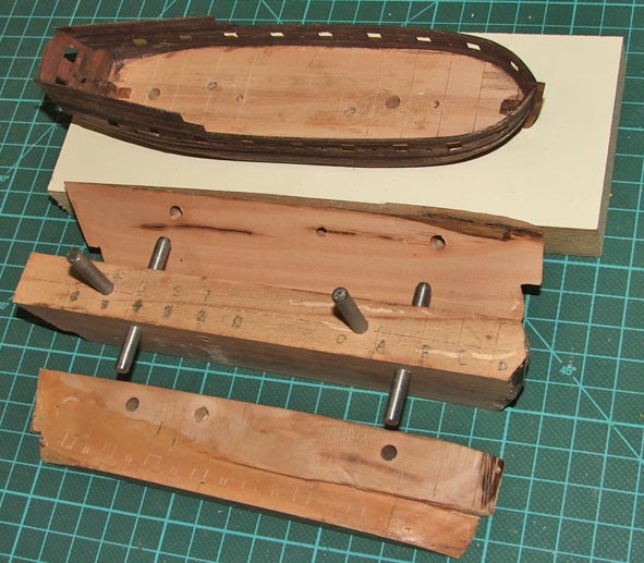
Guns As mentioned, Philadelphia and Washington carried a variety of guns from 6pdr to 18pdr. At 1:144 scale, the maximum diameters of these (excluding the reinforces) vary from 1.7 to 2.8mm, with the intermediate guns scaled proportionally. Working along the barrels, the differences in reinforce spacing for the different sizes are measured in fractions of a millimetre. On my Unimat SL lathe the taper (2 degrees) is easy to achieve by setting the headstock over, but generating the reinforces at the correct intervals rapidly taxed my mental arithmetic. Accordingly, I modified the lathe with larger graduated hand wheels and, more importantly, a digital readout along the axis. This greatly eased the problem of spacing the reinforces correctly. The results are shown here (a UK 5 pence piece is identical in size to a US dime). I spent some time trying to work out how to produce convincing shot to fill the shot garlands, given that at this scale the diameters are between 0.6 and 0.9mm (0.024”-.036”). In the end, I settled for poppy seeds. I haven’t mentioned the swivel guns. A visitor, peering into the box where the cannon barrels were stored, commented “Oh, you’ve got some bits of swarf here”. “Er…no…those are the swivels!”. (....to be continued)
- 30 replies
-
- 12
-
-
- philadelphia
- diorama
- (and 3 more)
-
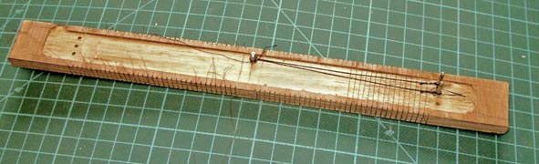
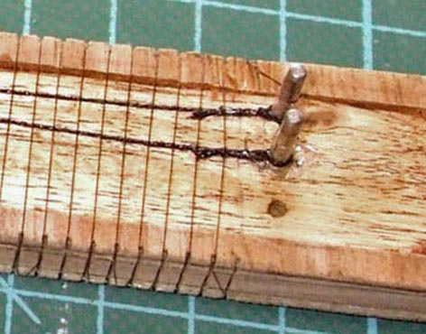
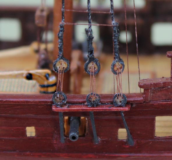
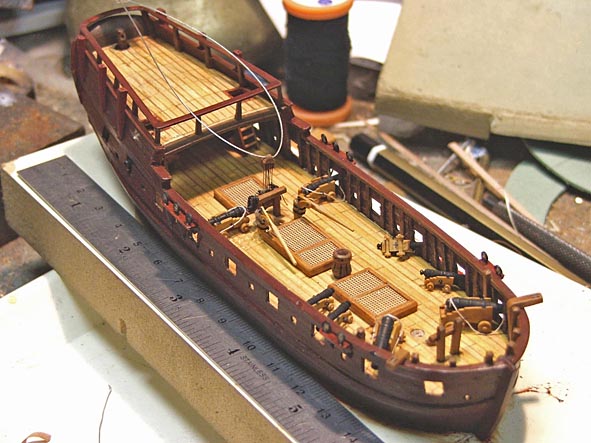
Fittings and details Both shells were screwed to separate blocks of chipboard for fitting out and the addition of much of the detail. Most of this was fairly routine and doesn’t rate a mention here, but there were a few points that may be of interest. Shrouds and ratlines I used black thread for the heavier standing rigging (shrouds and forestays) and brown or tan polyester cotton for lighter and running rigging. For the shrouds and ratlines I made a simple jig which is just a strip of plywood a little over twice the length of the shrouds with the surface hollowed to leave a shallow rim, and a series of saw cuts along each edge at the correct spacing for the ratlines (about 2.5mm at this scale). In the middle, I set a steel pin of the same diameter as the mast, and at each end a series of pins of the same diameter as the deadeyes. This allows both port and starboard shrouds to be made up at the same time. With the shrouds and appropriate lashings in place, I wrapped the entire length of the jig with cotton, using the saw cuts to regulate the spacing. I then painted each shroud with a diluted solution of PVA. Once that was dry, all the cotton outside the shroud assemblies was sliced away with a razor blade. Removing the steel pins leaves a set of shrouds ready to be attached to the mast. For deadeyes, I cut slices from a 2mm diameter plastic knitting needle – probably overscale, but I didn’t think I could drill three evenly-spaced holes in anything smaller than that – and then pressed them into the loops at the end of each shroud. The final result after adding the lanyards is shown here. (....to be continued)
- 30 replies
-
- 10
-
-
- philadelphia
- diorama
- (and 3 more)
-
Capt. Jack, Have a look at p.135 of Gene Bodnar's monograph on building 'Bluenose' (http://modelshipbuilder.com/e107_images/custom/msbimages/eisnor/bn-1-4/Bluenose%20Practicum%20Standard.pdf ). It reproduces a letter from the original builders listing all the colours used. John
-
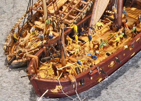
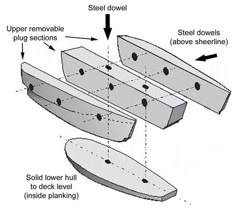
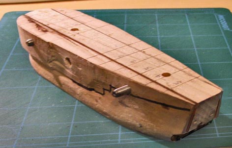
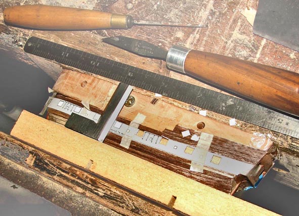
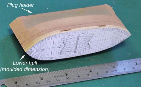
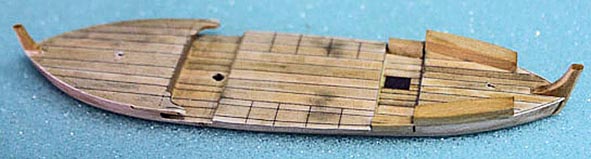
Washington Once the shell of Philadelphia was complete, but before starting to add the details shown in the last shot in the previous post, I put it aside and embarked on making the hull of Washington. This would be a waterline model, to be set into the water surface. My approach was similar to that used for Philadelphia, in that the part of the hull below deck level would be solid and incorporated in the finished model. In this case, however, the upper former was complicated by the fact that Washington had a tumblehome so the plug needed to be modified so that it could be extracted from the shell of planking. I made it in three pieces, located by steel dowels, in such a way that – once the planking was complete – the centre section could be lifted out and the side pieces collapsed inwards. This photo shows the degree of tumblehome, especially aft. With the upper former well coated with release agent (candle wax) and the lower former screwed to it, I was then able to plank the hull. Again, planking below deck level was glued to the lower former, that above simply edge butted. However, before removing the upper plug, I tacked a printout of the elevation to each side to enable the gunports and oar ports to be cut out. In this way, the sides – which at this stage are very fragile – are fully supported. Finally, I was able to remove the plug ready to reinforce the shell with upper frames and caprails, and to add the quarterdeck. Unfortunately, I seem to have let the camera take a holiday for a while and the next picture that I have shows the hull after painting and the addition of quite a bit of the detail. I will mention some of these items later…….and, yes, the guns really were of different sizes. Benedict Arnold’s fleet had been thrown together in a hurry, and Washington was armed with one 18pdr, one 12pdr, two 9pdr and six 6pdr cannons, plus numerous swivels. Keeping track of the ammunition must have been a nightmare. At this stage, a confession, which bears on the on-going discussion of what constitutes ‘scratch building’. The deck planking and gratings are computer printouts glued to the deck. I could probably have laid proper deck planking at this scale, but the gratings would definitely be beyond me. Is this still a scratch build? (....to be continued)
- 30 replies
-
- 13
-
-
- philadelphia
- diorama
- (and 3 more)
-
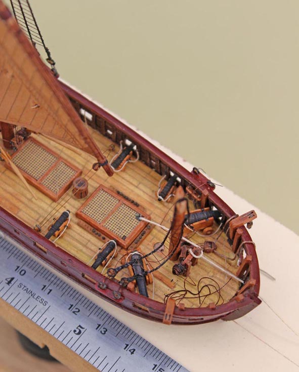
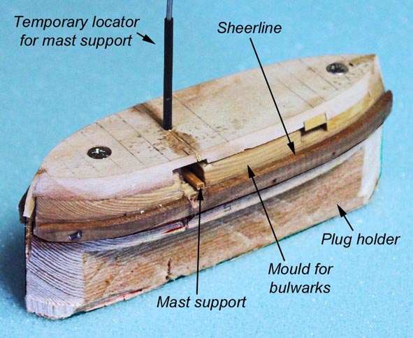
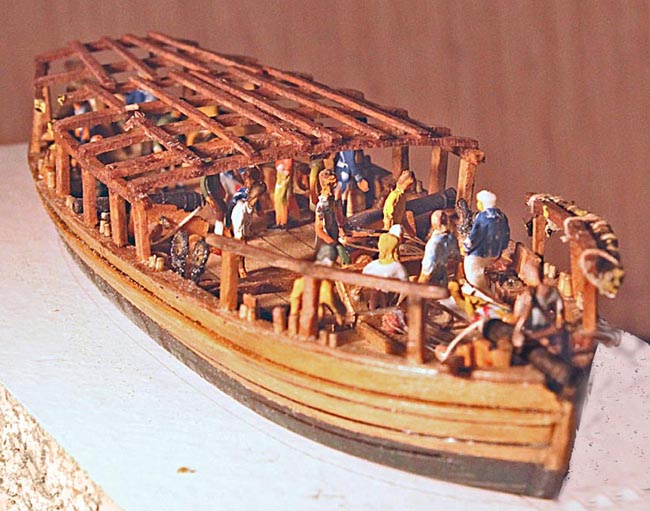
Philadelphia Philadelphia is flat bottomed with the deck at several different levels, so the starting point was a solid former made to the moulded (i.e. inside planking) dimensions of the below-deck area, screwed upside down to a plug so that the assembly could be held in a vice while the former was shaped to the hull contours. A print of the waterlines was glued to the base assists in this process. This former was to be planked and become part of the final model, so the next step was to remove it from the plug and add stem and stern posts and deck details (planking, lockers, etc.). A second former was cut to the moulded dimensions of the bulwarks, and a rail added to define the sheer line. This former would also be planked, but would need to be removed after planking and so I gave it a good coating of a release agent. I use candle wax dissolved in paraffin. The lower former was then attached and the whole assembly screwed to another plug. Because of the difficulty of aligning interior detail at this small scale, the mast support (essentially a large thwart) was inserted at this stage and held in place by a temporary rod so that it could be fixed to the planking as that progressed. I then planked the formers from the bottom up to the sheer line using 0.02” thick lime (basswood), with 0.04” lime for the wale. Below decks, the planks are glued to the former, while those above are simply edge-butted. I use PVA. Once that had dried, the screws were removed and the shell removed (gingerly) from the upper former. Having incorporated the mast support helps to give the shell some stability, which was then reinforced by adding internal knees and a capping rail. Unfortunately, I did not take any further photographs until a much later stage, after the awning support, guns and most of the figures had been added, However, the shape can be judged from the photo below. For ease of handling, the shell (which has a solid base) has been screwed to a block of ½” chipboard. (....to be continued)
- 30 replies
-
- 11
-
-
- philadelphia
- diorama
- (and 3 more)
-
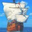
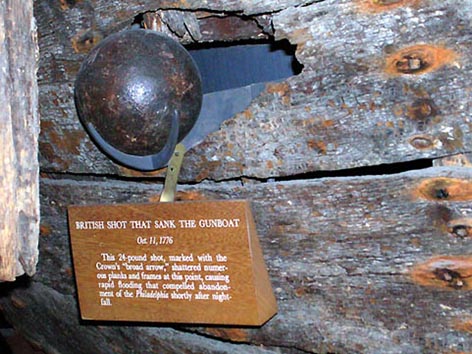
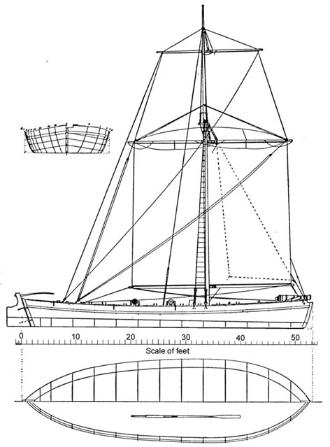
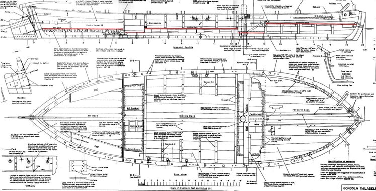
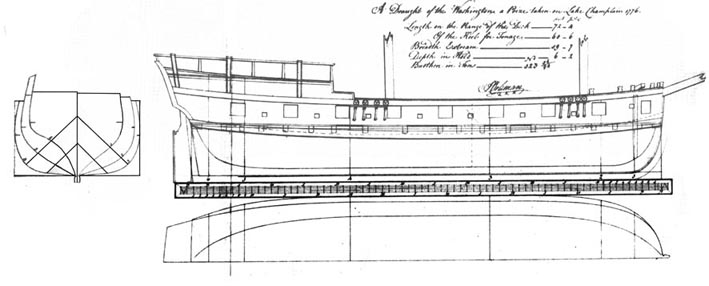
Background It has been suggested that I should post a retrospective build log for my diorama of the sinking of the US gondola Philadelphia during the Battle of Valcour Island, Lake Champlain, in 1776. The final result is shown under “Diorama” in the gallery of completed scratch builds. A retrospective log may be unusual, but I hope that there are one or two ideas that others may find useful. If too many people get fed up with it, I’m sure they’ll tell me. The story started when I saw the Philadelphia in the Smithsonian in Washington DC. Although she sank in 1776, she was recovered in 1935 and is now on display, complete with the 24pdr British cannon ball that sank her. The Smithsonian has published a set of plans which I obtained (with some difficulty!)... .....but Philadelphia is a pretty basic and crudely built barge, and I decided that it wouldn’t make a very interesting model on its own. However, there is a modern painting by Earnest Haas of the US galley Washington standing by the Philadelphia and taking off the crew (Photo 4), and it struck me that this would form a good diorama. Washington was captured later in the battle, and the Admiralty, as was common practice, took off her lines. The draft is now in the National Maritime Museum in UK, and has been reproduced in a number of books. (I should add that my model was built before NRG published the plans for Washington). Although both vessels were small (Philadelphia is 53’7” OAL and Washington was about 80’ OAL), I have run out of room for large glass cases, so I decided on a scale of 1:144. (......to be continued)
- 30 replies
-
- 7
-
-
- philadelphia
- diorama
- (and 3 more)
-
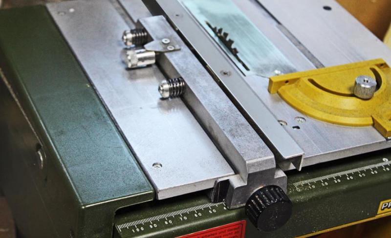
Looking at Mark's photo of the MicroMark, it appears to me that the Proxxon is for all practical purposes identical. This is my Proxxon, to which I have added a micrometer-adjustable fence. I find it will cut pretty consistently to +/- 0.003". John