John Garnish
-
Posts
84 -
Joined
-
Last visited
Content Type
Profiles
Forums
Gallery
Events
Everything posted by John Garnish
-
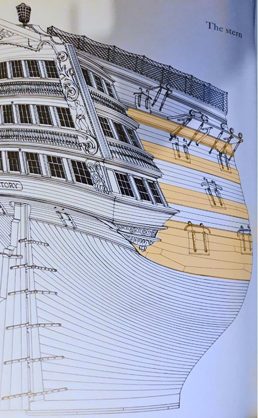
 Seren, Another (distorted) photo from McGowan's book. Note that there is another wale supporting the channels.
-
Siren You are right in wanting to include the wales, because they are essential to the appearance of the model. I attach a photo of the side elevation from Alan McGowan's book. The photo is very distorted because of the curvature of the pages, but the positions of the wales is still pretty clear. I have tinted them to help. Note that, if you want to be really accurate, the lower wale uses anchor stock planking. John

-
Building on the above, the fore and mainstays will be the heaviest ropes, followed by the shrouds and backstays in decreasing order and finally down to ratlines and lanyards. A golden rule for rigging models is that, if in doubt, make it lighter rather than heavier.
-
Don, This is purely a guess, because I haven’t tried it, but it seems to me that one of the characteristics of a weathered hull is that the seams crack and the individual planks start to show. It may be possible to simulate this, after painting the base colour on the hull, by using some slightly textured paint (paint with some dust in it?) and touching in each plank separately. That may provide the necessary delineation and texture. Any treatment of the planking prior to painting seems more likely to merge the planks rather than to delineate them.
-
Apologies if I am missing something, but I haven't seen any reference in this discussion to Harold Hahn's book 'Ships of the American Revolution', and specifically to his chapter on Oliver Cromwell/Beaver's Prize. She started out as a merchantman, converted to a privateer in 1777. She was about 90ft OAL, marginally smaller than a Cruizer-class brig, and pierced for 18 guns (though the forward ports would rarely be filled). Originally, the complement was 12 six-pounders, later increased to 14 and then 16. That description seems to fit fairly well with what Lou is trying to build. Hahn's chapter on Oliver Cromwell also goes a long way to answering questions about the size, shape and spacing of gun ports, and the positioning of one (and later two) capstans. He even mentions that his model was built as a substitute for a commission to build Davis' Lexington!
-
Kurt, I have used diluted PVA glue to veneer furniture. The veneer was still holding 20+ years later. It should work for this as well. Simply brush the diluted solution onto one surface, lay up the veneer, and then iron with a medium-hot iron. Depending on veneer thickness, you should be able to lay up several sheets in one pass. A sheet of paper between wood and iron would be a precaution against scorch marks. It's very quick, so you could run a test in about 5 minutes.
-
I should have mentioned that the formed shape of the sail will still be quite fragile, so you should avoid handling it more than necessary. That means that you should have fixed the sail to the yard and attached to it all the necessary rigging lines (tacks, clews, braces, buntlines, bowlines, etc.) before forming it to shape.
-
I would use diluted PVA adhesive, brushed on. Fix the sail in a realistic position - (perhaps not on the model) - and then use a hair dryer to blow the sail into shape and dry the glue at the same time.
-
I have used both acrylic-based and water-based sanding sealer, and I don't think there is much to choose between them in terms of performance. However, it is much easier to clean brushes after the water-based sealer, so I tend to use that all the time now. However, I do not sand the result when dry. I use only medium grade wire wool, which leaves a much finer finish and does not blur sharp edges. It also has the advantage that you use it in small throw-away bunches, so it never clogs. A word of caution - it can burn spectacularly, so keep it away from flames.
-
Thank you, Georges. I am a great fan of ANCRE and your group, so I am sure that you are correct. I'm just surprised that I had never seen this before. Entirely my own fault - I have had a copy of "The 74 Gun Ship" since soon after it was published, and there it is - clearly shown in Fig.197 - but I had never noticed its significance.
-
I have never before seen a breeching rope that goes through the gun carriage rather than round the cascabel. How common was this? The wear rate must have been terrific.
-
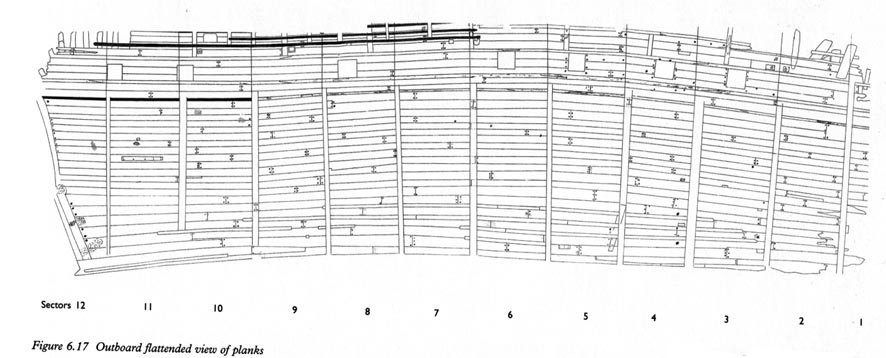
No-one has mentioned the Mary Rose, launched in 1511 and sunk in 1545. The remaining starboard side was raised in 1982 and is now on display in Portsmouth Dockyard (UK). The remains have been well-documented in “Mary Rose: Your Noblest Shippe”, edited by Peter Marsden (2009). It should be remembered that the Mary Rose was 34 years old when she sank, having spent a hard life in the Western Approaches and taken part in two battles before her final loss, and having undergone numerous repairs. She can therefore be taken as a fair representation of shipbuilding practices in the early sixteenth century. The material in Peter Marsden’s book addresses two of the issues discussed in this forum, the type of planking, and typical plank lengths. Fig 6.17 of the book provides a flattened (projected) view of the surviving starboard side. It shows planks of widely varying widths (and thicknesses) and includes drop planks and stealers. Planks are typically end-butted (but without any great care to ensure verticality), and the shift of the butts is pretty random. It also shows the result of several repairs. There is a relevant paragraph in the text, as well: “The length of each plank varies from 1.47m to 10.85m, but most are between 4.5m and 9m long, the longer planks mostly being in the midships area. The shorter planks, those of less than 3m, are low down in the hull at the bow or stern and between the second and third wales (Fig. 6.16b). All the shortest planks, less than 2.75m, are between the gunports.” The overall impression is that the choice of materials was dictated largely by what came to hand rather than a strict adherence to ‘rule’, but there were clearly substantial lengths of timber available. The message seems to be that, if one is attempting to model a ship of this period, it shouldn't look too tidy.
-
Planking processes
John Garnish replied to MESSIS's topic in Building, Framing, Planking and plating a ships hull and deck
Christos, Yes. Measure around the midships frame or bulkhead from keel to wale on one side. This will tell you how many strakes of planking you will need. For example, suppose the measurement is 156mm and you are using 7mm planks, you will need 23 strakes. For each bulkhead, cut a strip of paper equal to the distance from keel to wale, mark 23 divisions along it and then transfer these marks to the bulkhead. The easy way to do this division process is to draw two vertical lines on a sheet of paper, each easily divisible by the number you have just calculated (in this case 23), one longer than the maximum length around the bulkhead and one shorter than the distance around the shortest bulkhead. In the example I have given, you might choose 184mm and 92mm. Divide each one, and join the marks: Now you can take any of your strips of paper, lay it on the diagram so that the ends lie on the top and bottom lines, and mark off the 23 divisions. Once you have marked the bulkheads, you will be able to see the line to follow for each strake. You may find that, as you reach the ends of the hull, the strakes become too wide or too narrow – in which case you will need to think about stealers or drop planks, but that’s a matter for a separate discussion. You should read the primers on planking elsewhere on this forum, e.g. http://modelshipworldforum.com/resources/Framing_and_Planking/Plank_Bending.pdf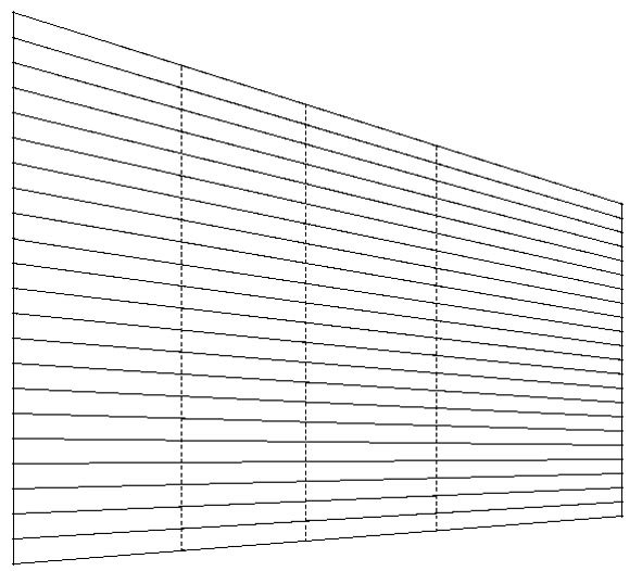
-
Planking processes
John Garnish replied to MESSIS's topic in Building, Framing, Planking and plating a ships hull and deck
Christos, Don't worry - it's not as complicated as it sounds. Once you have tapered a plank, I doubt whether you will be able to tell which edge is which. That's particularly true once the plank has been softened (by whatever means) for bending, because when you fit it in place it will also deform up and down to fit to the adjoining plank. As long as you have marked the frames to ensure a true line along the planking, all you need to do is ensure that each plank follows the line. -
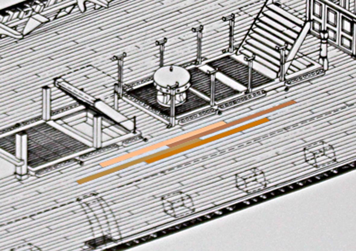
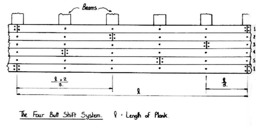
Deck planks will always start and finish on a deck beam. These will not always have a uniform separation, so plank lengths will vary slightly. For Victory, plank lengths of 6-7 metres would be typical. Planks were laid in the 4-butt shift pattern. This is shown in this picture, taken from Peter Goodwin’s “The Sailing Man of War”. There are also detailed, if slightly idealised, drawings of each deck of Victory in Alec McGowan’s book. The following is a detail of the middle gundeck, in which I have coloured one set of planks to show how it works. You can see also that a typical plank length is a little less than the spacing between alternate gunports. There is also a lot of information on this question in the thread http://modelshipworld.com/index.php?/topic/9495-1760s-royal-navy-deck-planking-and-waterway-nibbing-patterns/&do=findComment&comment=280393 on this forum.

-
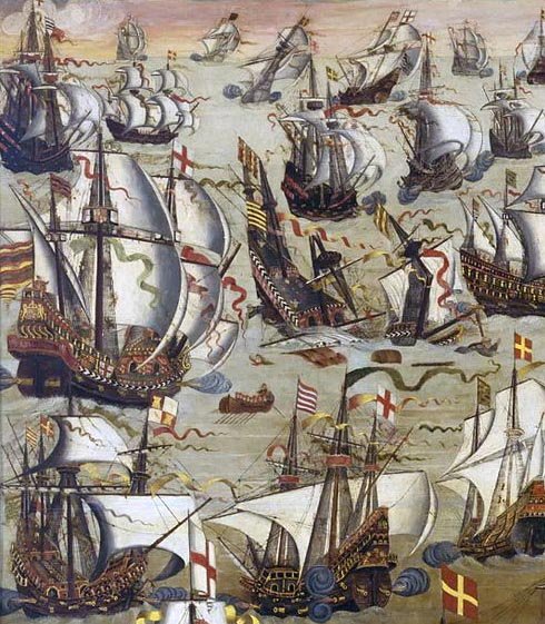
Kurt, I don’t know of any hard evidence for the start of this practice. The earliest example of which I am aware is the NMM’s model of Boyne (1692), built by the master shipwright himself, which does have red bulwarks. Research on the Mary Rose (sunk 1545) has shown a few traces of paint on the external surfaces of one or two fragments, but nothing on internal surfaces. Similarly, there is considerable evidence of paint remaining on the many carvings of the Wasa (1628) but, except for mouldings in the captain’s cabin, there is no mention of paint inside the hull. One of the guide books states “Traces of paint have also been found on certain furnishings, but none anywhere on the hull. Tar and linseed oil seem the only things to have been applied to that.” Absence of evidence is not evidence of absence, of course. However, a near-contemporary panting of the Battle of Gravelines (August, 1588) does show the inner bulwarks of several vessels, none of which seem to carry a predominantly red colour: My gut reaction is that painting the inner bulwarks probably began in the mid-seventeenth century. For anything earlier than that, I suggest that it would be safer to leave the bulwarks in a natural wood colour.
-
Apologies to Mike and Allan for my mistake in the last post. The comment was, of course, from Allan.
-
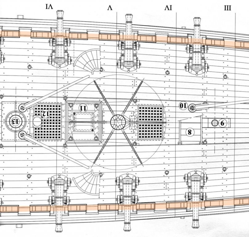
Mike's comment is particularly true in the case of smaller ships, up to and including frigates. The following is an extract from Plan 7B of the ANCRE book “L’Aurore” (18 gun frigate of 1697-1720) by Jean‑Claude Lemineur & Patrick Villiers: This ship had a significant tumblehome, so I have shaded in the line of the top of the gunports. It is clear that, even at full recoil within the confines of the other deck fittings, the muzzles would barely have cleared the ports.
-
I think the answer is that it would be on whichever side it was left on after the last sustained tack. John
-
Thanks, Pete. Glad to be of help. I think you can fit a set of parrels to your model with a clear conscience.
-
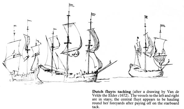
Pete, I think the answer to your last point is that the lateen yard would rarely be shifted from one side of the mast to the other. You can see the same thing in Arab dhows today, where they seem to perform almost as well with the sail pressed to the mast as they do on the other tack. There is a frustrating lack of information in the reference books about the handling of lateen sails. Steel doesn’t seem to mention them (though the absence of any index, combined with the small print, makes a detailed search difficult). The only possibly useful pointer I have found is an illustration in Harland (p.181), apparently from Van de Velde, which seems to show a fluit tacking without shifting the lateen or disturbing the mizzen topsail. Without informed guidance, it is worth going back to basic principles. The purpose of the lateen sail (and, to a lesser extent, the later driver) is principally to provide balance to the rig (i.e. lateral drag) rather than forward drive. In the absence of a working sail aft to push the stern round, it would be virtually impossible for a square rigger to pass through stays. For that reason alone, it is extremely unlikely that the lateen would be brailed up during a tack. As forward drive is less important, any loss of aerodynamic efficiency on one tack rather than the other would be fairly unimportant. Remember also the previous discussion about the location of the mizzen topsail braces. Attempting to swing the lateen yard vertical would sacrifice any control of the mizzen topsail, which would then flog uncontrollably – just what one needed at that moment! Note, too, that the Van de Velde drawing shows no suggestion of the mizzen topsail being brailed up or allowed to flog. I would suggest, then, that this is the answer to the apparent paradox of a truss that made it difficult to tip the yard vertically: it would be done only occasionally and at leisure, once the ship was settled on a very long reach (i.e. hours if not days) and the truss could be freed off, the mizzen topsail handed, and the yard swung vertical.
-
Pete, The attached PDF is an extract from Lees' "Masting & Rigging...". If I read it correctly, a parrel was used until about 1773, when it was superseded by a served rope loop. parrel006.pdf In that sense, the system shown on the Royal William model is correct in principle but simply 50 years too late for the 1719 refit. John
-
ROYAL WILLIAM LATEEN YARD
John Garnish replied to piratepete007's topic in Masting, rigging and sails
Pete, James Lees' "The Masting and Rigging of English Ships of War 1625-1860" gives no diagram of the mizen topsail braces, but says the following about them: "Braces, up to 1805, led aft with the standing part made fast to the mizen yard or gaff. The running part rove through the brace pendant blocks, back through single blocks on a span round the mizen yard or gaff just below the standing part and the brace led down to the rails by the transom. Until about 1670, blocks on the mizen yard were about 8ft down from the standing part; after then the standing part and the blocks were very close, about a foot separating them." I would suggest, then, that your rigging diagram should look more like this and, no, you're not being thick. The original drawing is a nonsense.
-
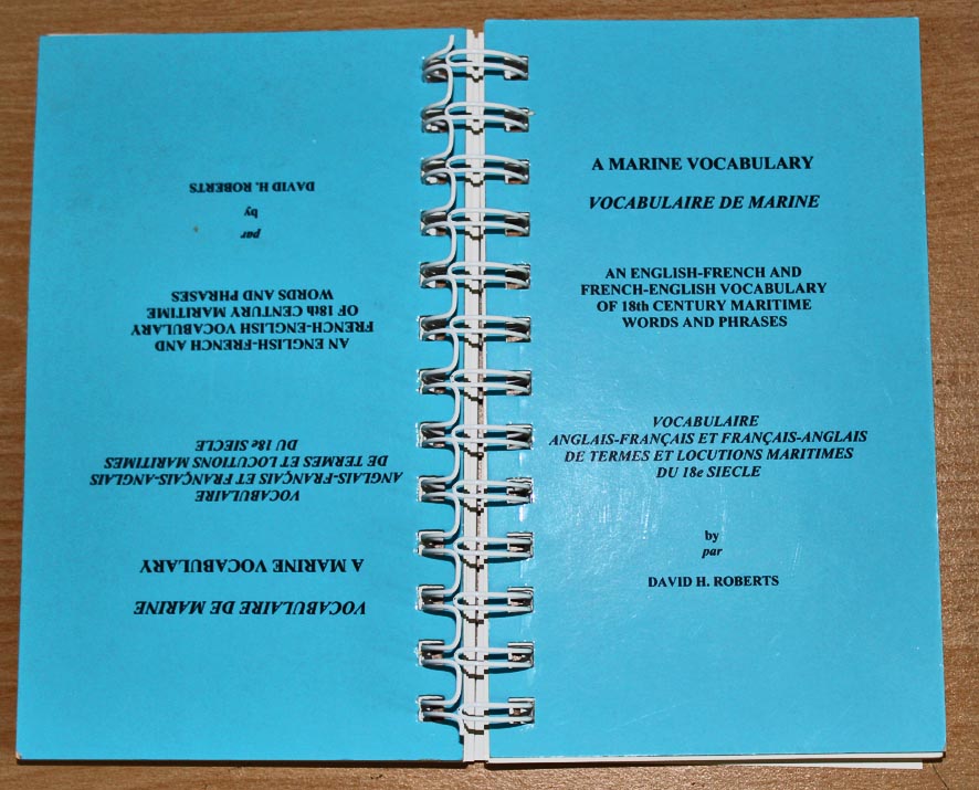
The dictionary is well worth-while. I'm used to reading technical reports in French, but the marine terminology is far from intuitive. For instance, the French for mizzen mast is artemon, which is what we call the foremast on Roman vessels, while the French for foremast is misaine ! If you didn't know this, it would be easy to have the ship going backwards.
-
If you have to get one of the French monographs, ANCRE also sell a first-rate double-ended French-English dictionary of maritime terms ("A Marine Vocabulary") by David Roberts, who was Jean Boudriot's translator.