DocBlake
-
Posts
1,811 -
Joined
-
Last visited


-
 CiscoH reacted to a post in a topic:
Armed Virginia Sloop by DocBlake - FINISHED - Model Shipways - 1/48 Scale
CiscoH reacted to a post in a topic:
Armed Virginia Sloop by DocBlake - FINISHED - Model Shipways - 1/48 Scale
-
Archi reacted to a post in a topic:
Royal Yacht HMY Fubbs 1682 by DocBlake – 1:24 Scale - Stern Section
-
Archi reacted to a post in a topic:
HMY Fubbs 1682 by Mike 41 - FINISHED - Weasel Works – Stern Section – 1:24
-
Landlubber Mike reacted to a post in a topic:
Royal Yacht HMY Fubbs 1682 by DocBlake – 1:24 Scale - Stern Section
-
Landlubber Mike reacted to a post in a topic:
Royal Yacht HMY Fubbs 1682 by DocBlake – 1:24 Scale - Stern Section
-
Landlubber Mike reacted to a post in a topic:
Royal Yacht HMY Fubbs 1682 by DocBlake – 1:24 Scale - Stern Section
-
Landlubber Mike reacted to a post in a topic:
Royal Yacht HMY Fubbs 1682 by DocBlake – 1:24 Scale - Stern Section
-
 Thanks, Mike!
 -
Mike 41 reacted to a post in a topic:
Royal Yacht HMY Fubbs 1682 by DocBlake – 1:24 Scale - Stern Section
-
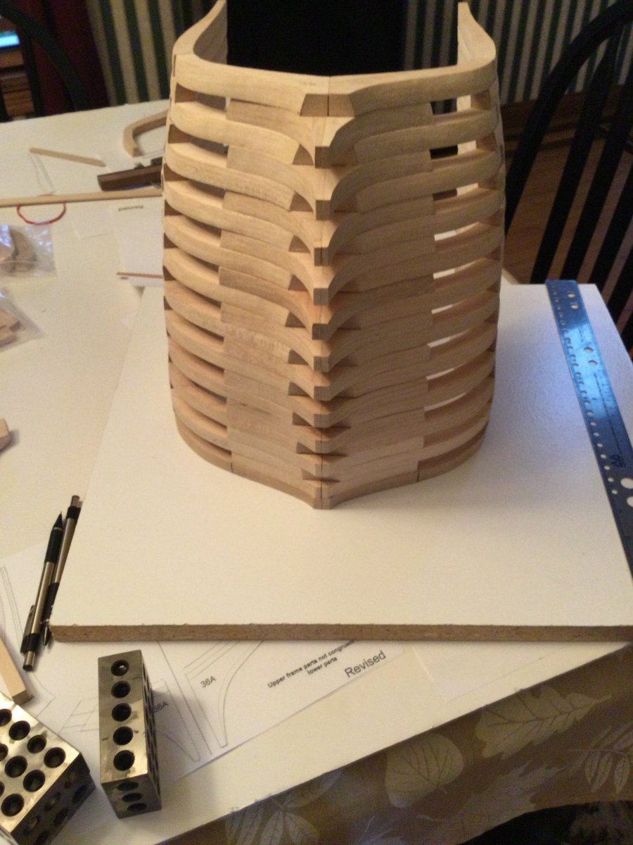
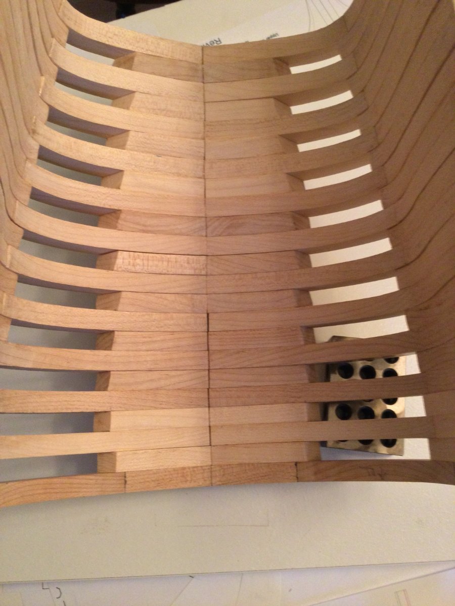
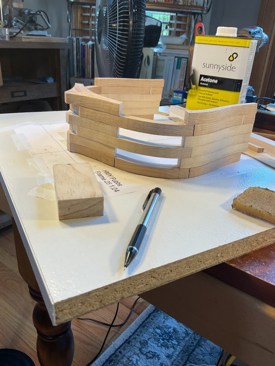
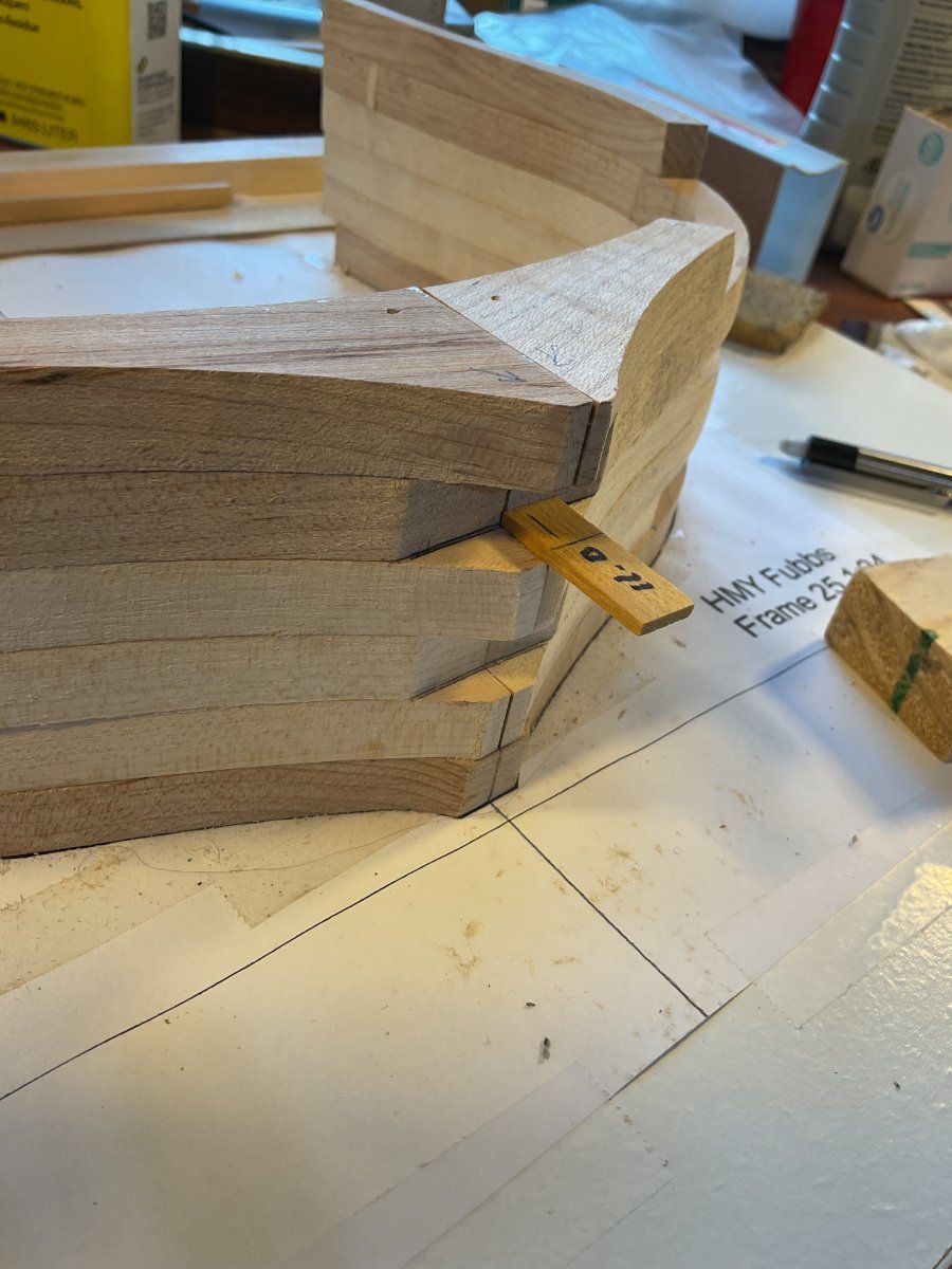
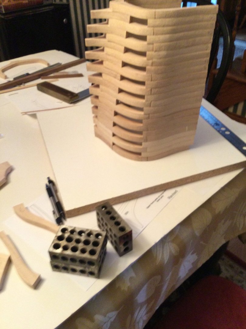
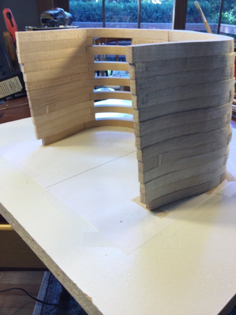
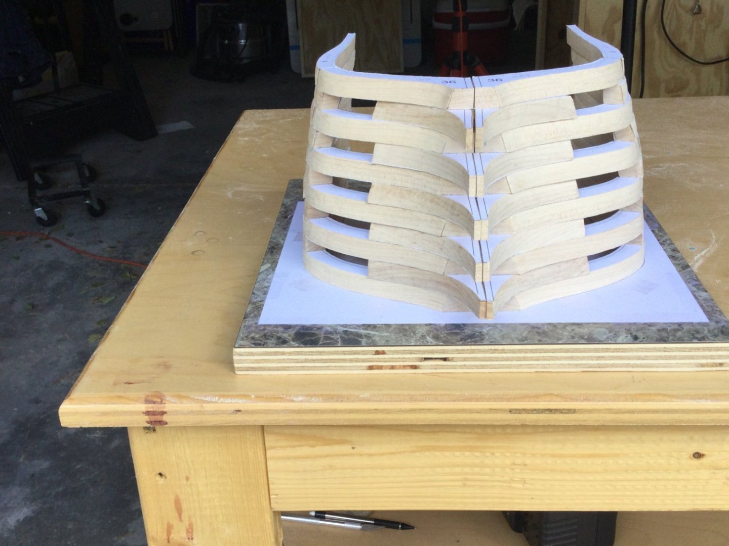
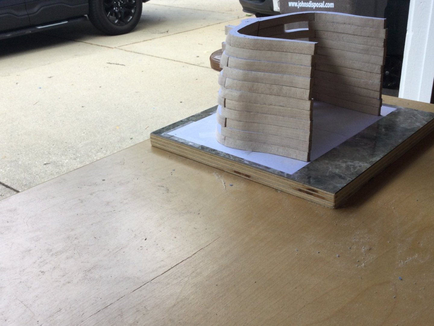
I glued up two stacks of frames: Frame 25 - Frame 30A and Frame 31 - Frame 36. I stacked these on each other. The two stacks are not glued together yet, just pinned, and I haven't started fairing the hull either.


-
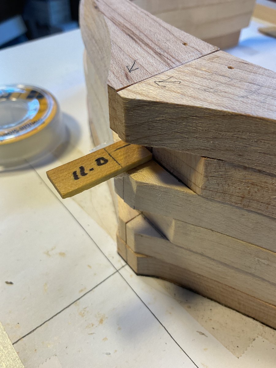
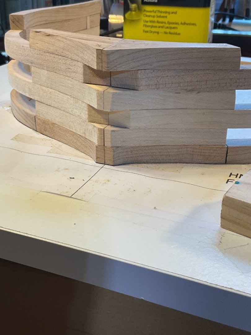
Here are the four 2/32" brass pins to register the joint between frame 30A and frame 31.
-
Frames 25 through 30A are glued into place, but there has been no fairing of the hull yet. Frame 31 is sitting on top of the stack, not glued. It will start the second stack of frames. Once the second stack is glued up, the two stacks will be glued together. I'm considering adding a couple of removable brass pins to join Frame 30A and Frame 31 and "register " a perfect fit once the stacks are complete. They would keep the frames oriented to each other and prevent any slippage as the glue dries. I guess I'll sleep on it!


-
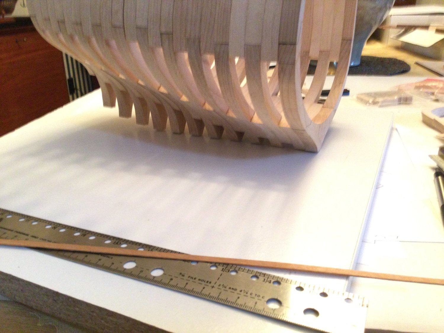
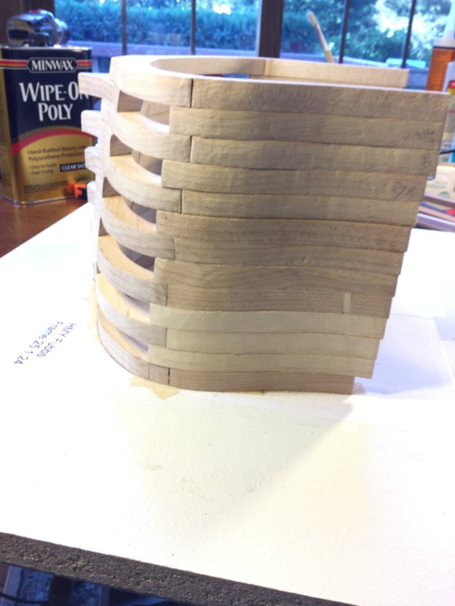
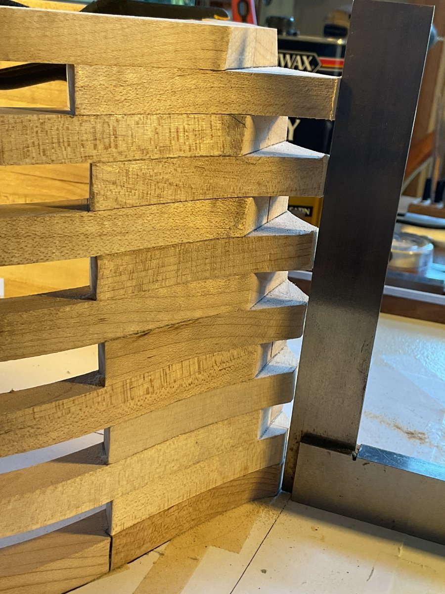
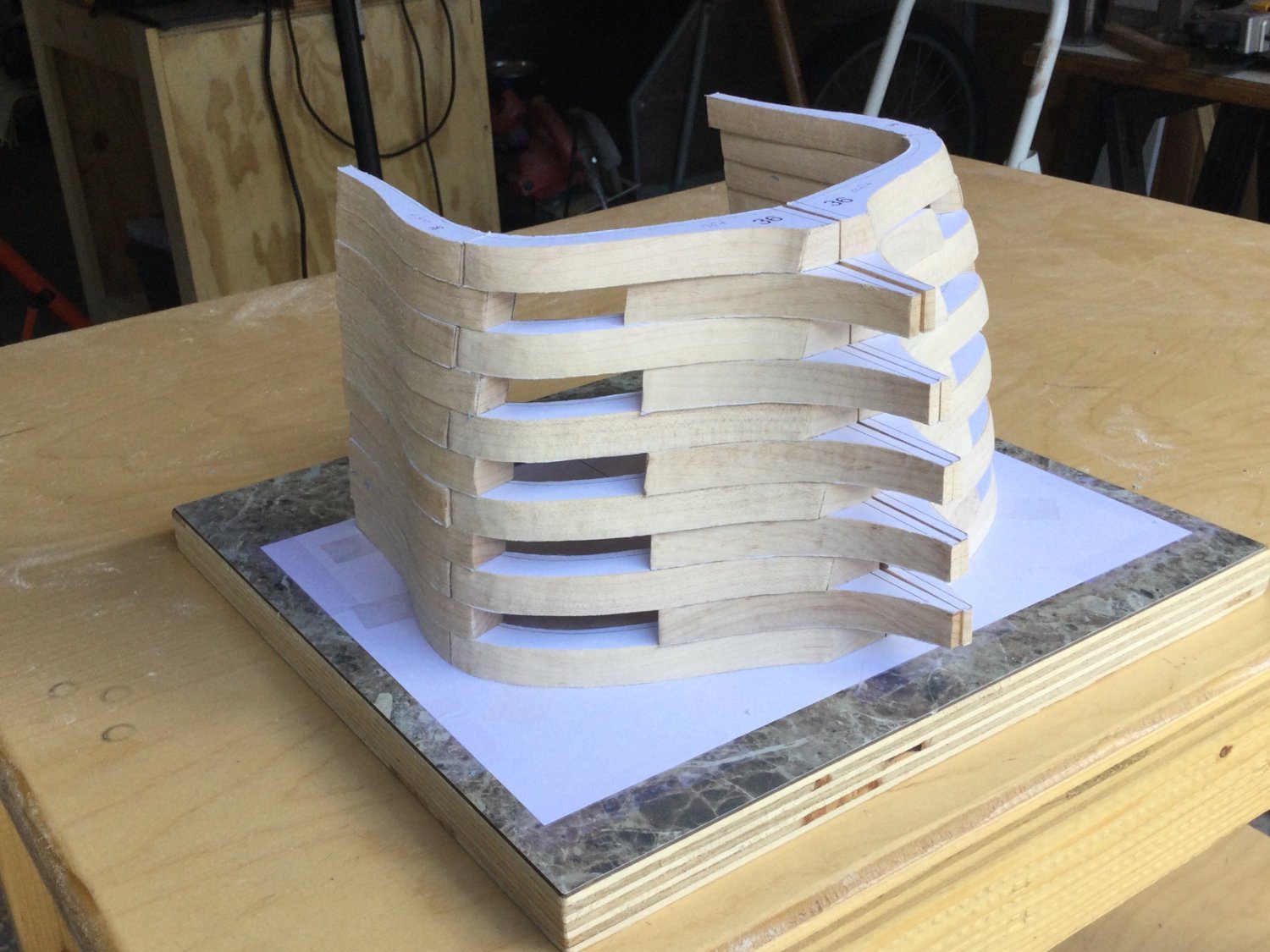
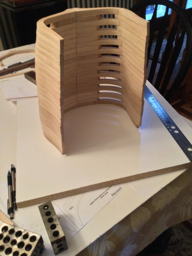
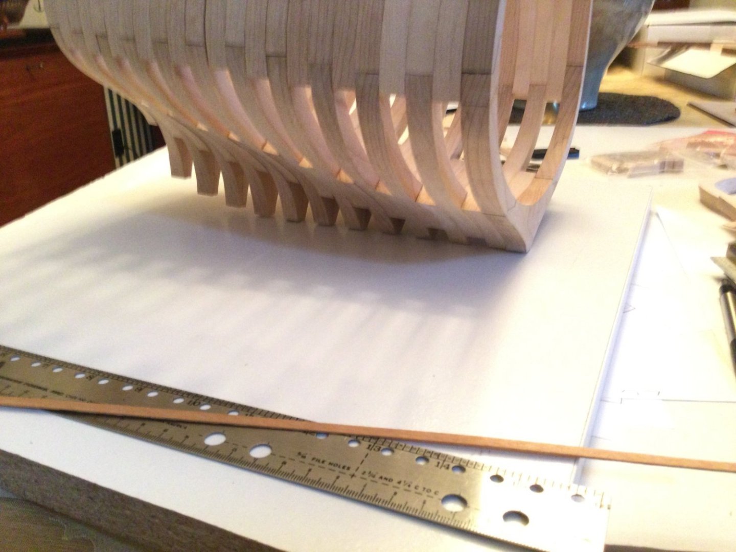
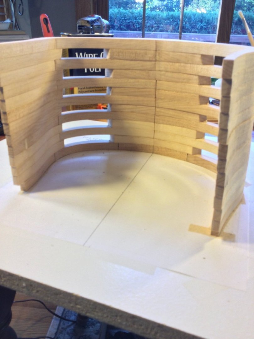
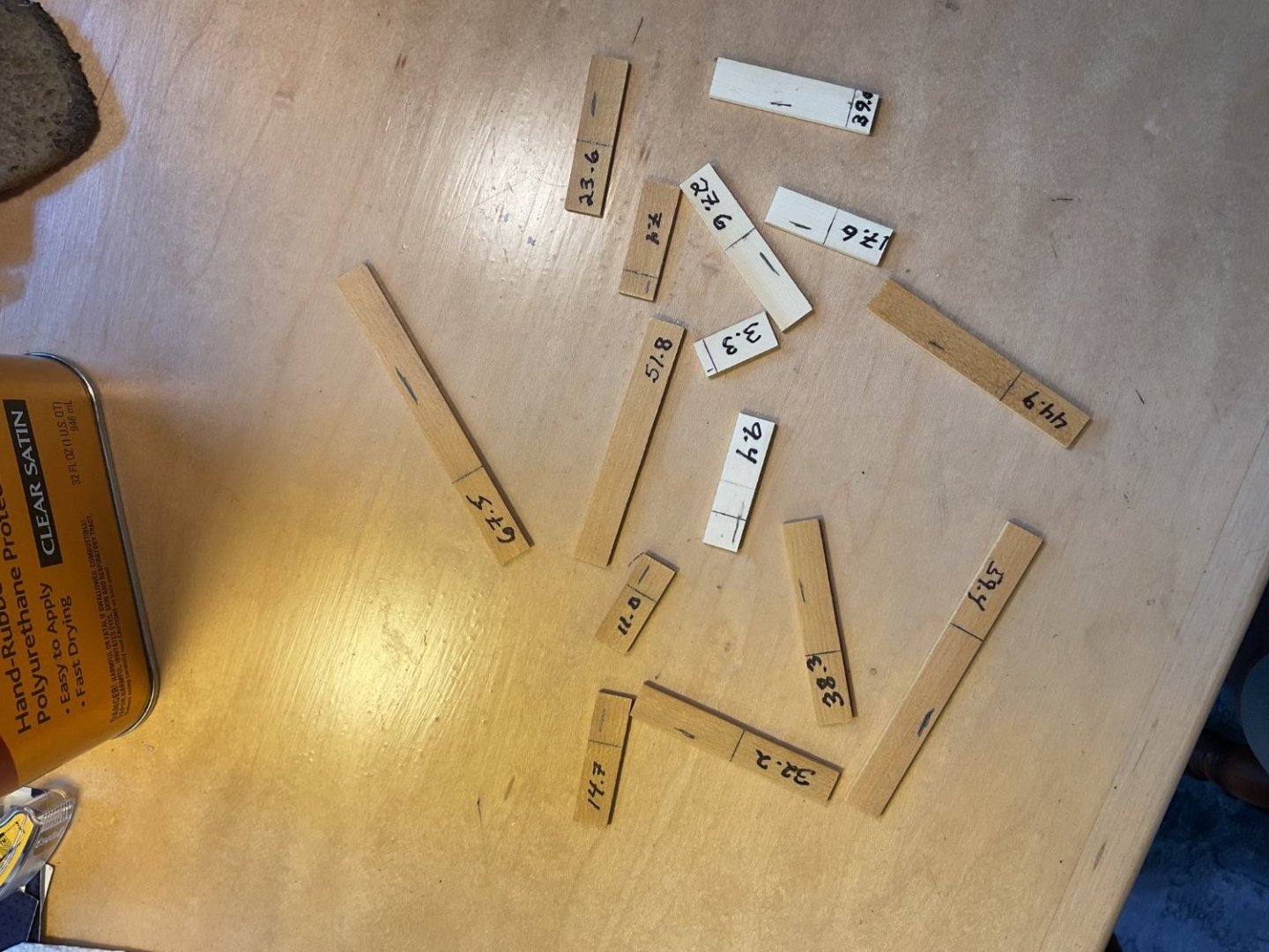
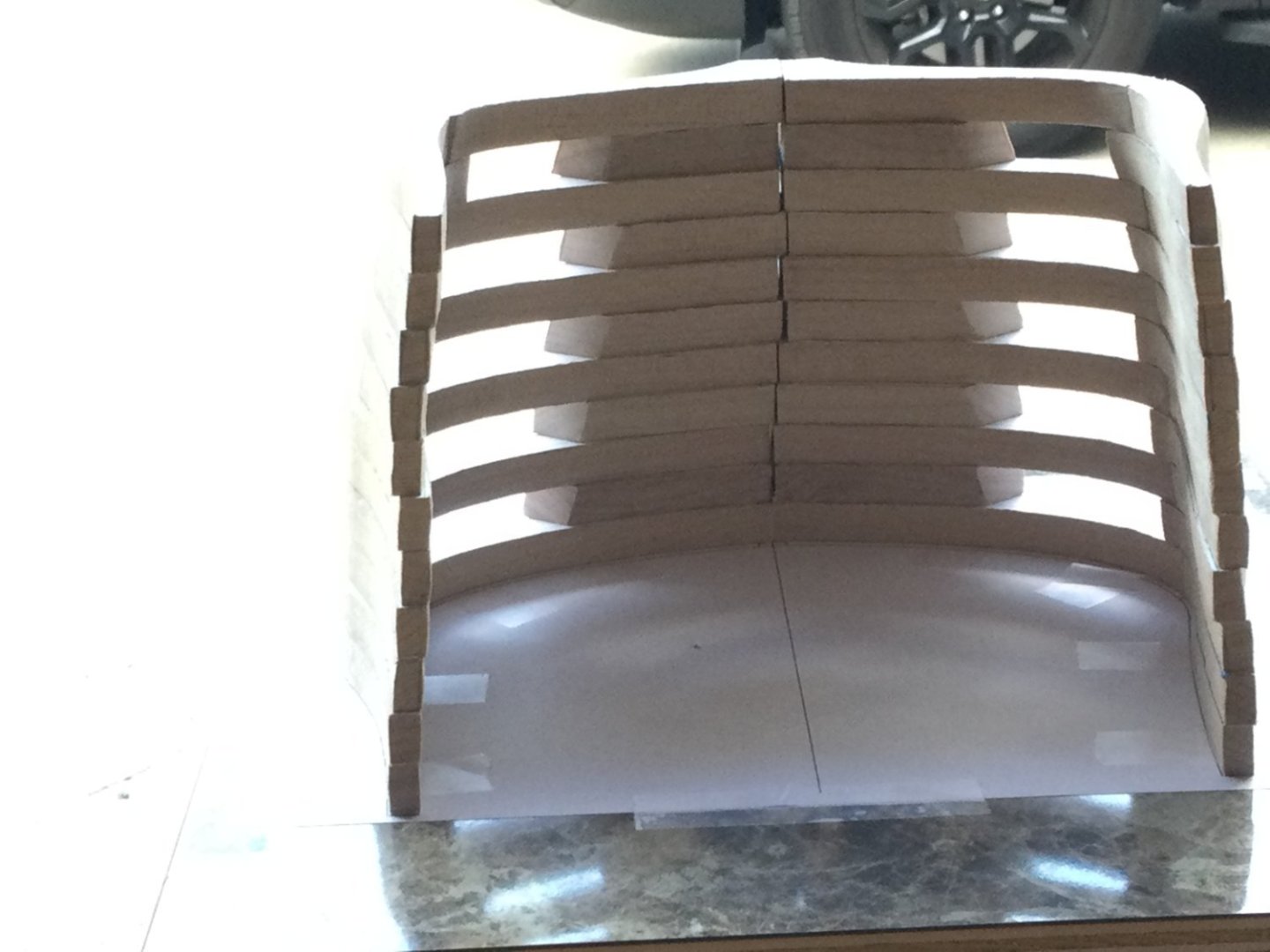
Thanks, guys! Progress so far: The first 6 frames are installed (25 - 27A). The most important measurement is how high above the keel the futtock frames sit. Each is different, increasing in distance as we move aft. To make checking this easier, I drew to proper dimension on thin pieces of stock; each measurement having it's own little "ruler". Eliminates the difficulty of trying to read the tiny gradations on a metric rule! After frame 25, each frame moving aft has it's top timber about 1.5 mm higher than the frame in front of it. You can see the "saw-tooth" pattern developing along the top timbers


-
 DocBlake reacted to a post in a topic:
HMY Fubbs 1682 by Mike 41 - FINISHED - Weasel Works – Stern Section – 1:24
DocBlake reacted to a post in a topic:
HMY Fubbs 1682 by Mike 41 - FINISHED - Weasel Works – Stern Section – 1:24
-
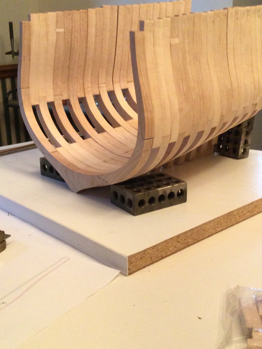
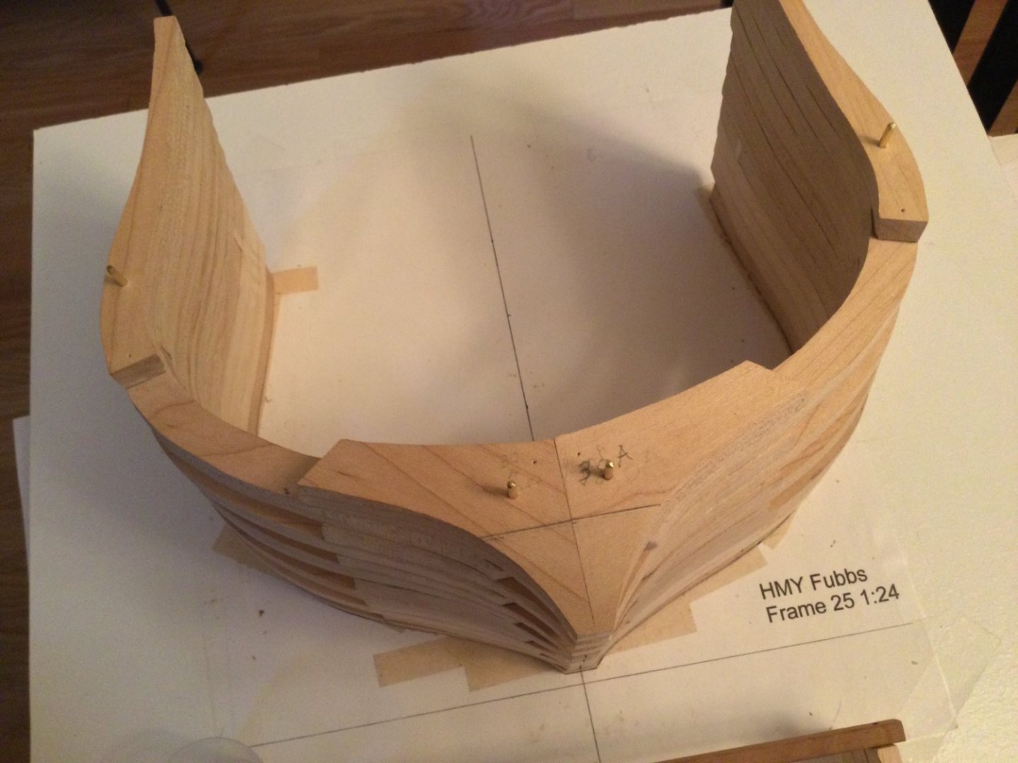
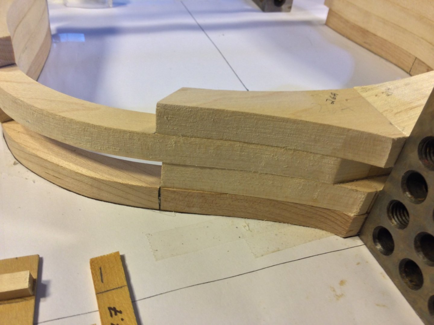
I finally got around to starting the glue up. I used double sided tape to tape the fore side of frame 25 to the template sheet and glued part 25A to it. This was followed by 26 and 26A. The floor frames (25A, 26A, 27A etc.) rest directly on the keel up until frame 32. The futtock frames sort of "float" above the keel, sandwiched in by the floor frames in front and behind them. The "offset" of these frames is important in establishing the shape and esthetics of the hull. Jodie's build log explains this well. The distance between the bottom of frames 26 and 27 and the keel is supposed to be 7.4mm and 11.0 mm respectively. Mine were very close to those numbers. So far, so good!


-
Awesome work!
-
DocBlake reacted to a post in a topic:
HMY Fubbs 1682 by Mike 41 - FINISHED - Weasel Works – Stern Section – 1:24
-
Great progress, Mike! She's looking great.
-
DocBlake reacted to a post in a topic:
HMY Fubbs 1682 by Mike 41 - FINISHED - Weasel Works – Stern Section – 1:24
-
DocBlake reacted to a post in a topic:
HMY Fubbs 1682 by Mike 41 - FINISHED - Weasel Works – Stern Section – 1:24
-
DocBlake reacted to a post in a topic:
HMY Fubbs 1682 by Mike 41 - FINISHED - Weasel Works – Stern Section – 1:24
-
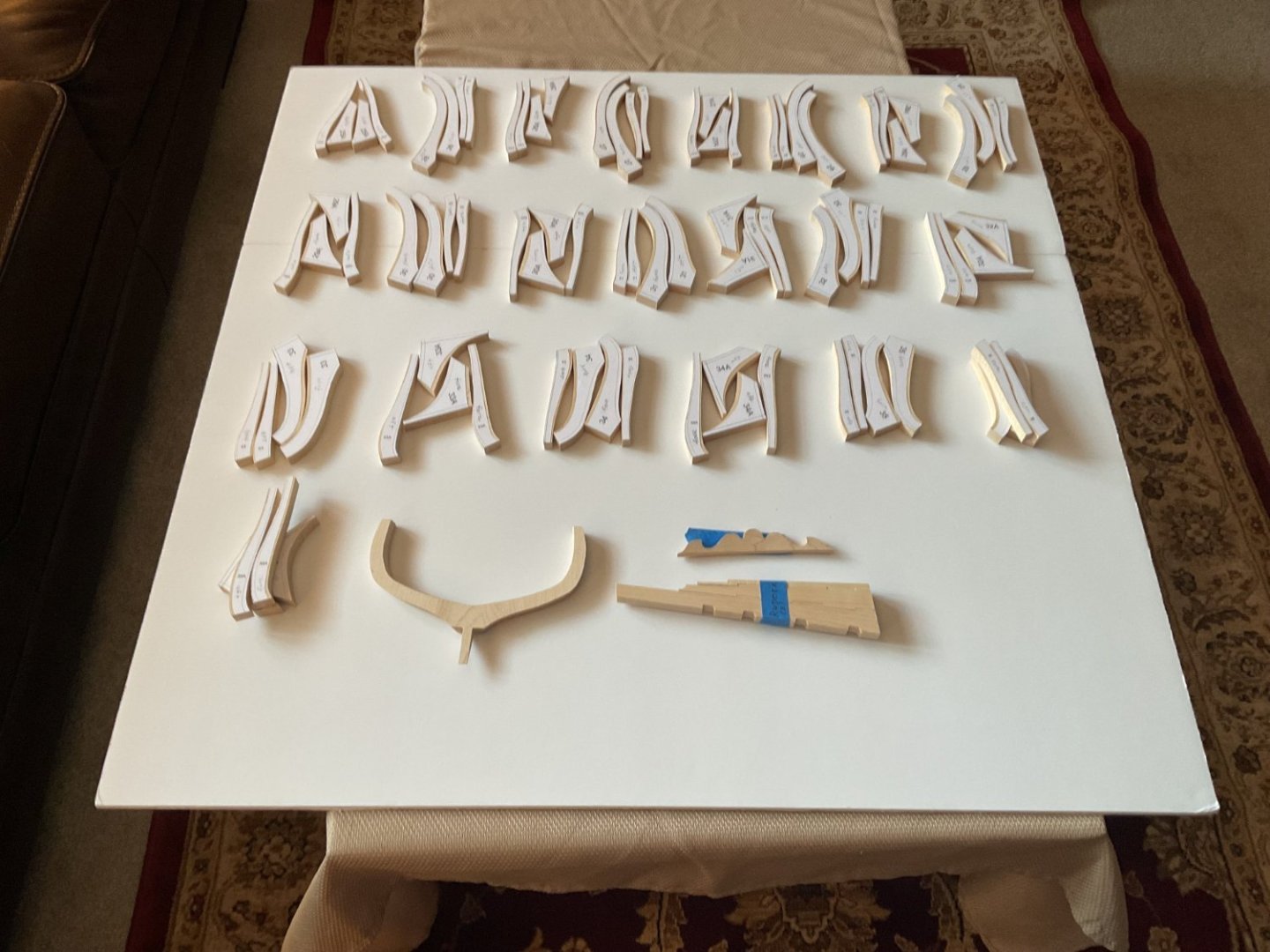
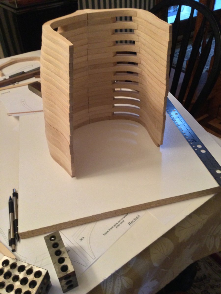
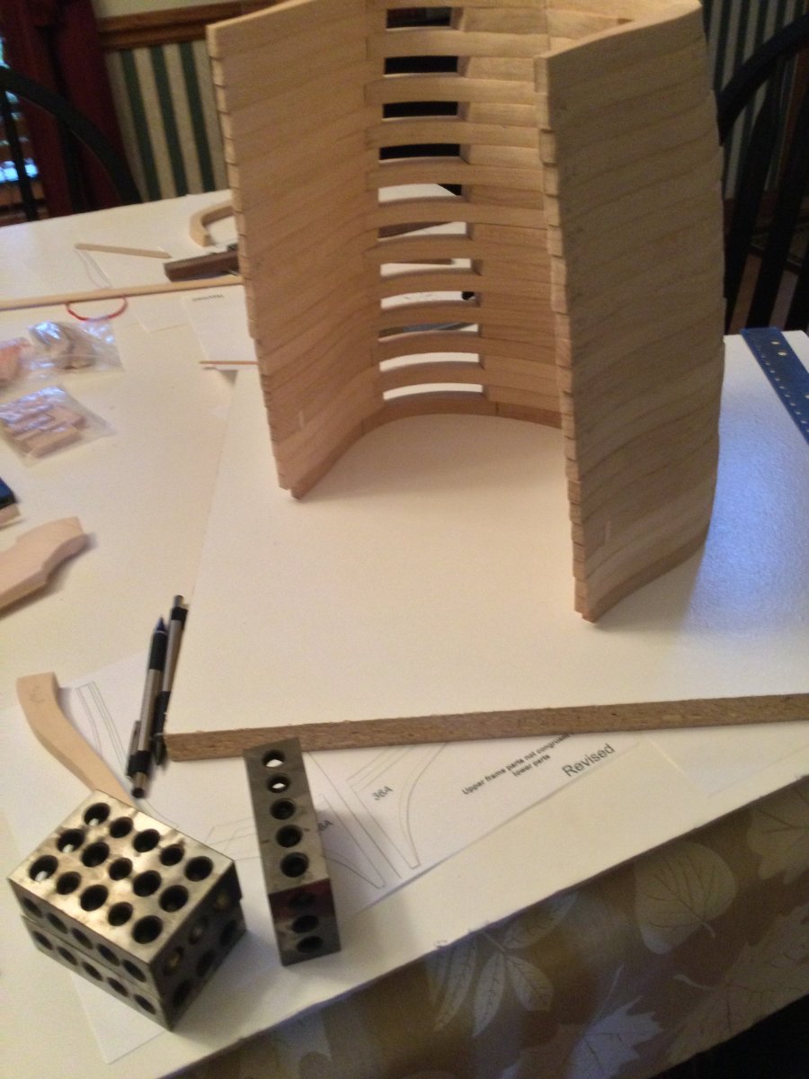
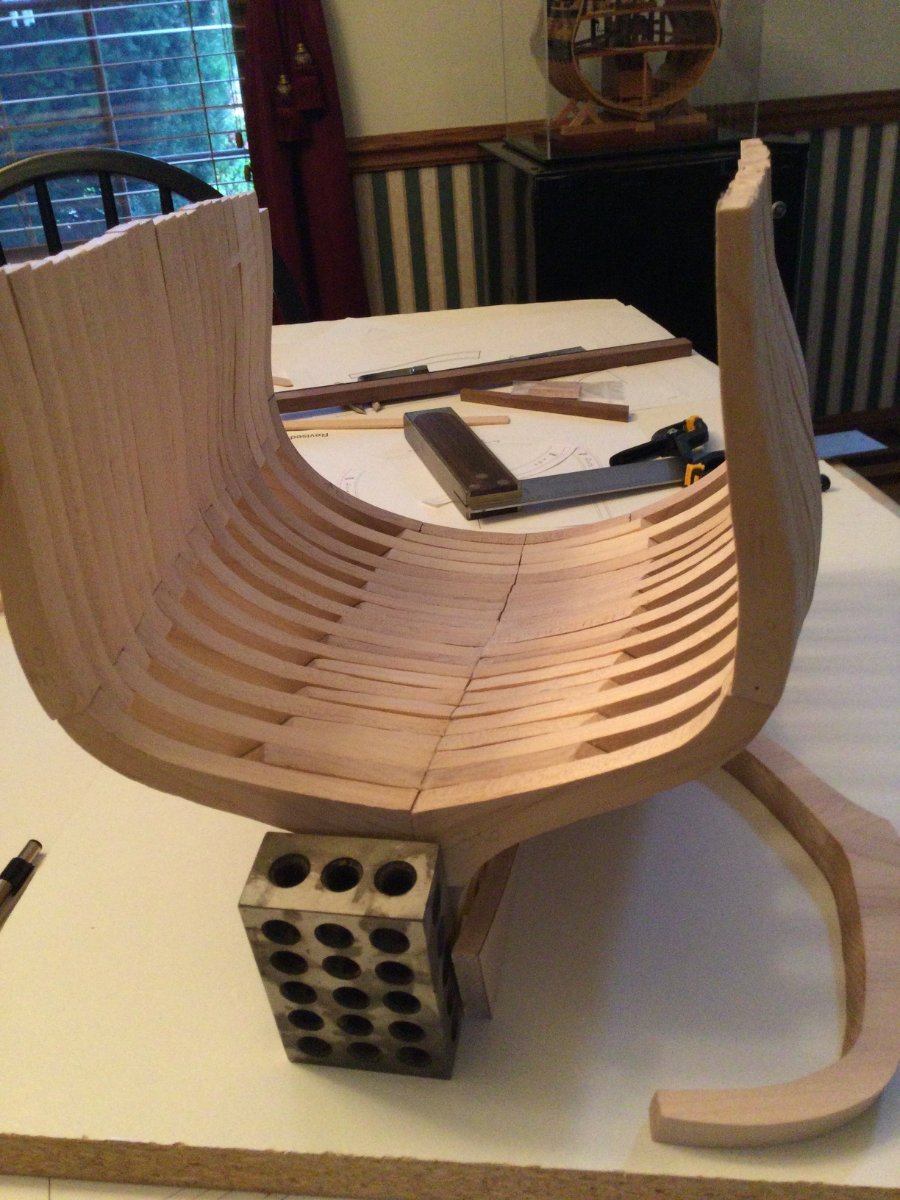
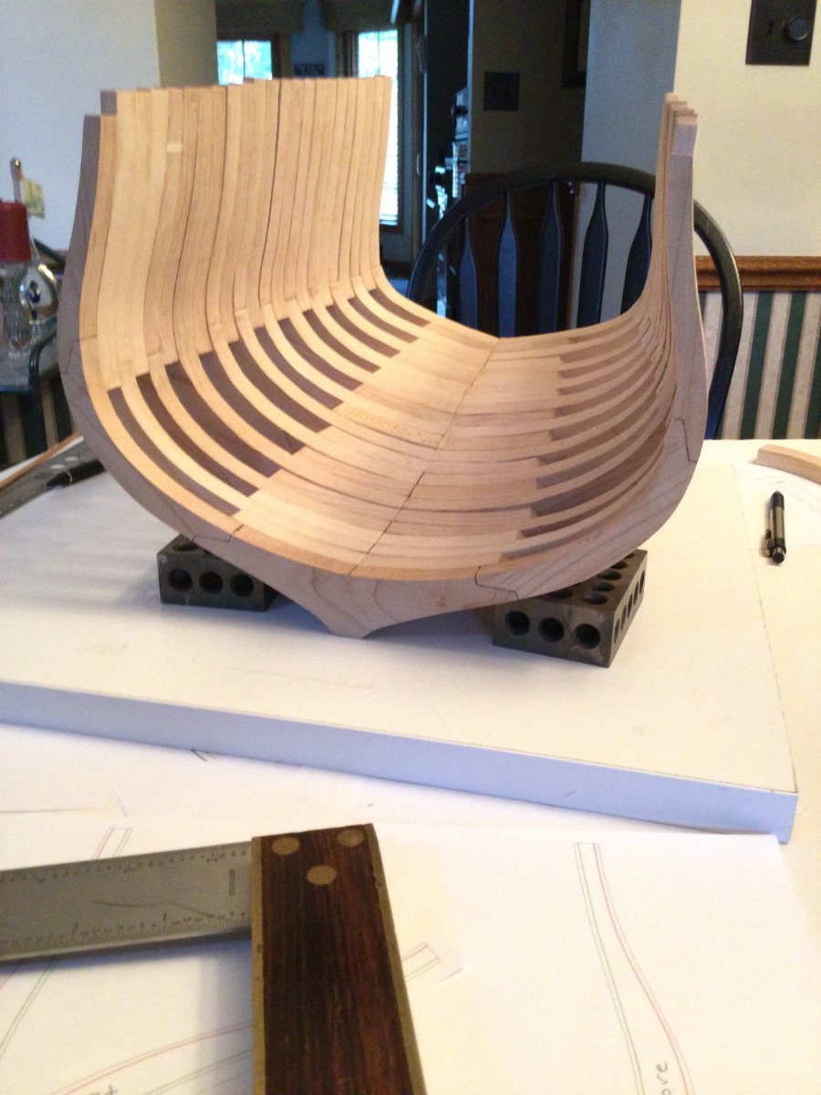
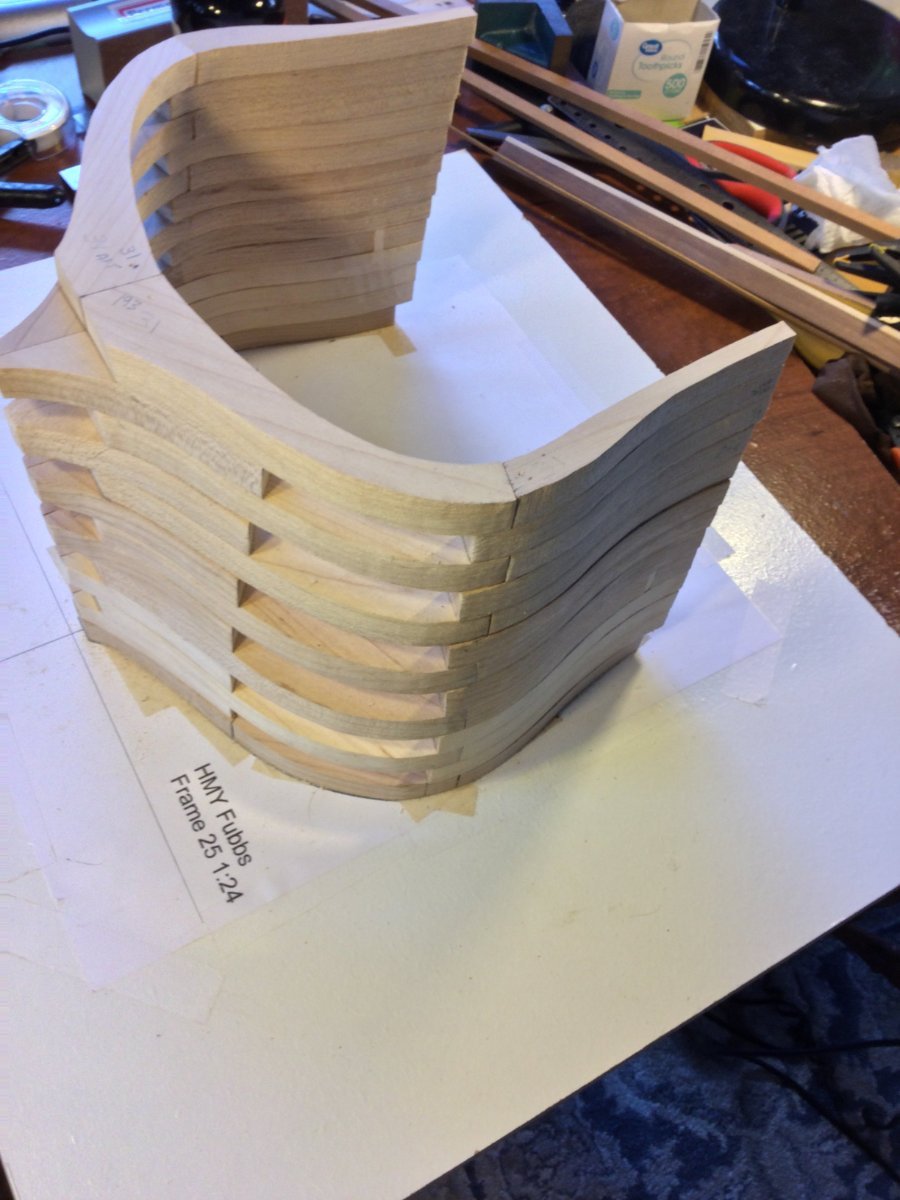
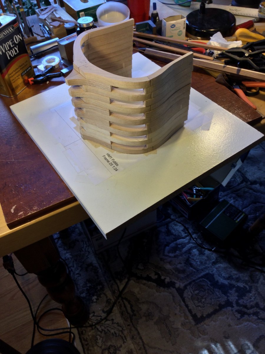
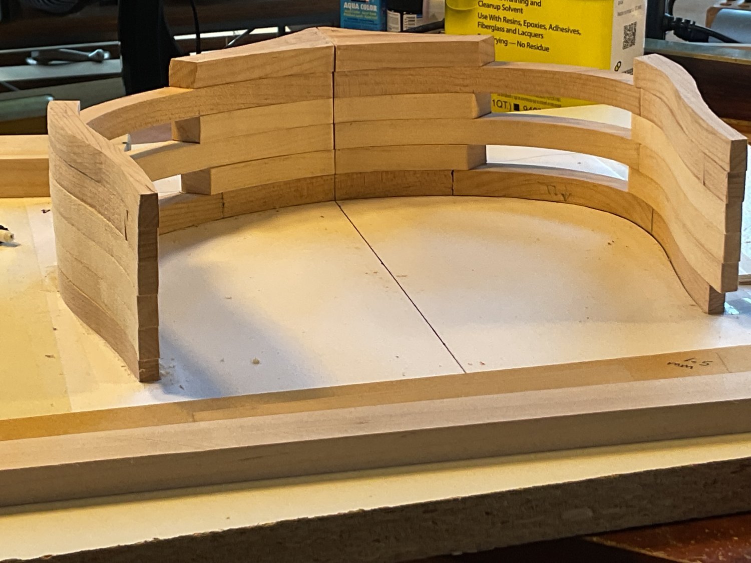
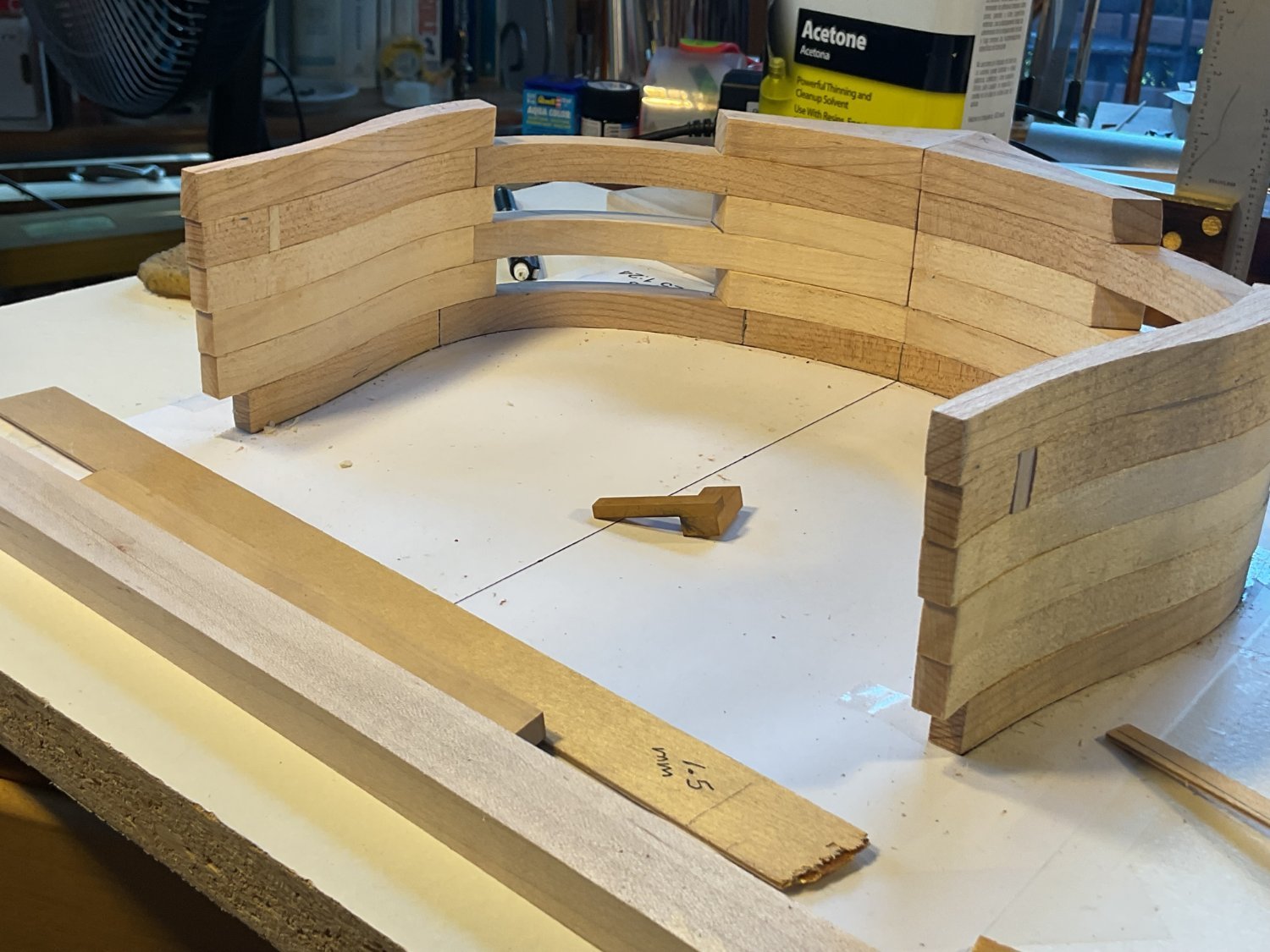
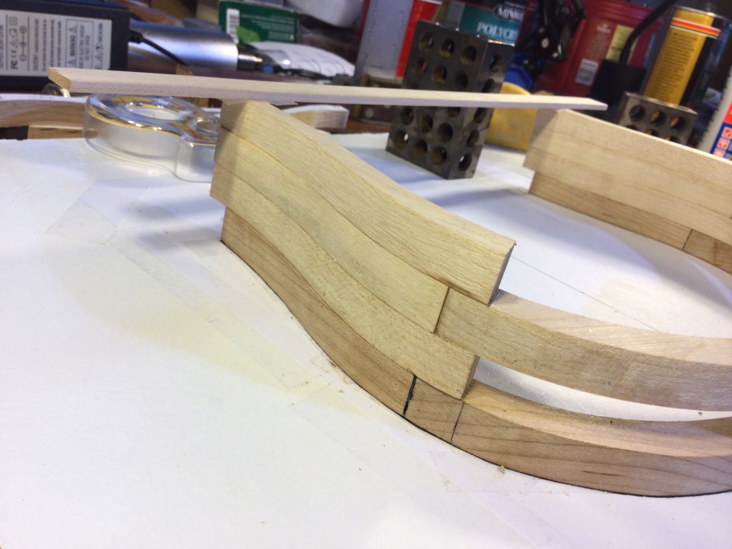
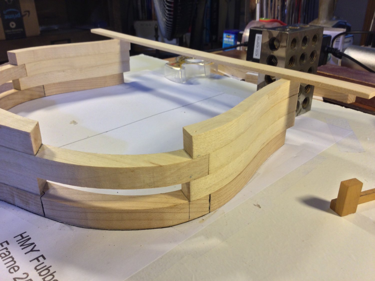
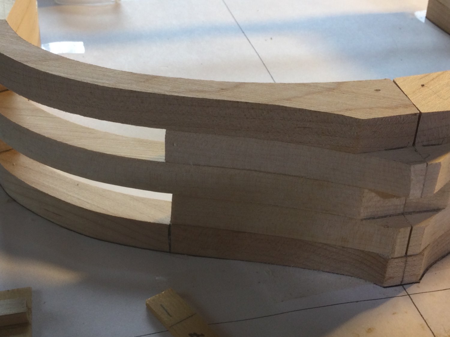
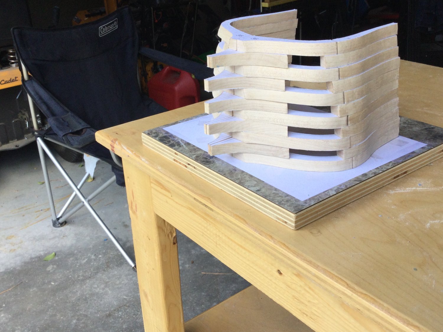
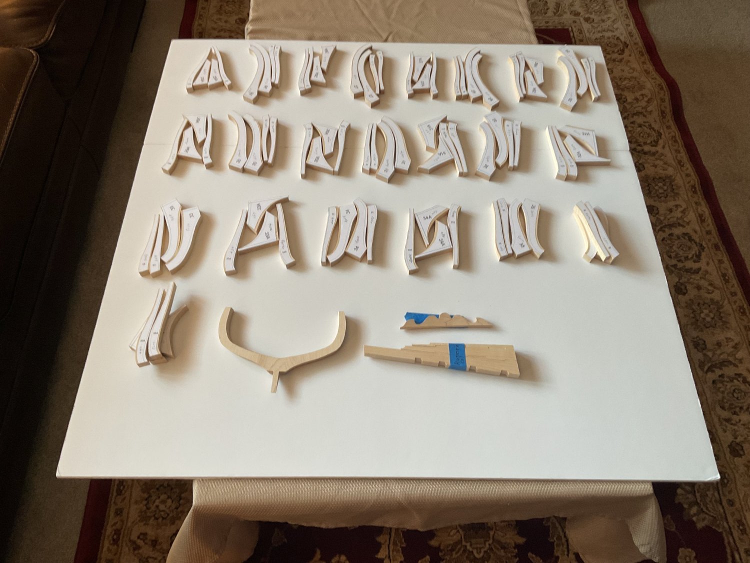
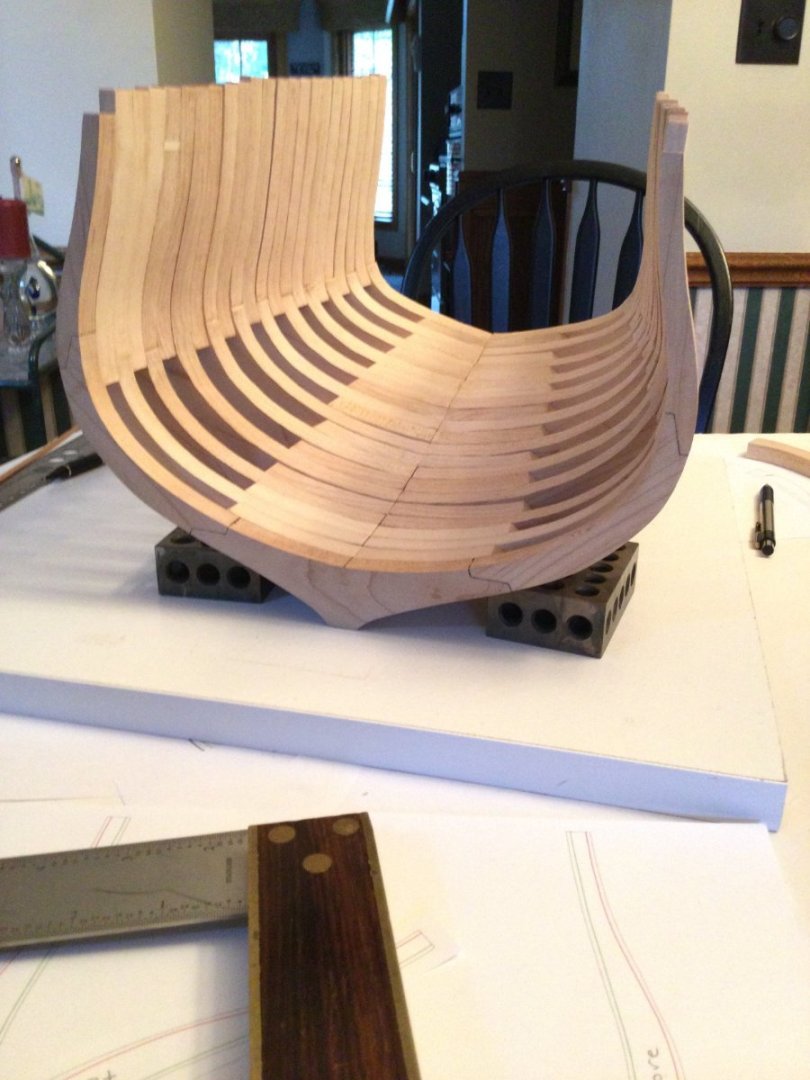
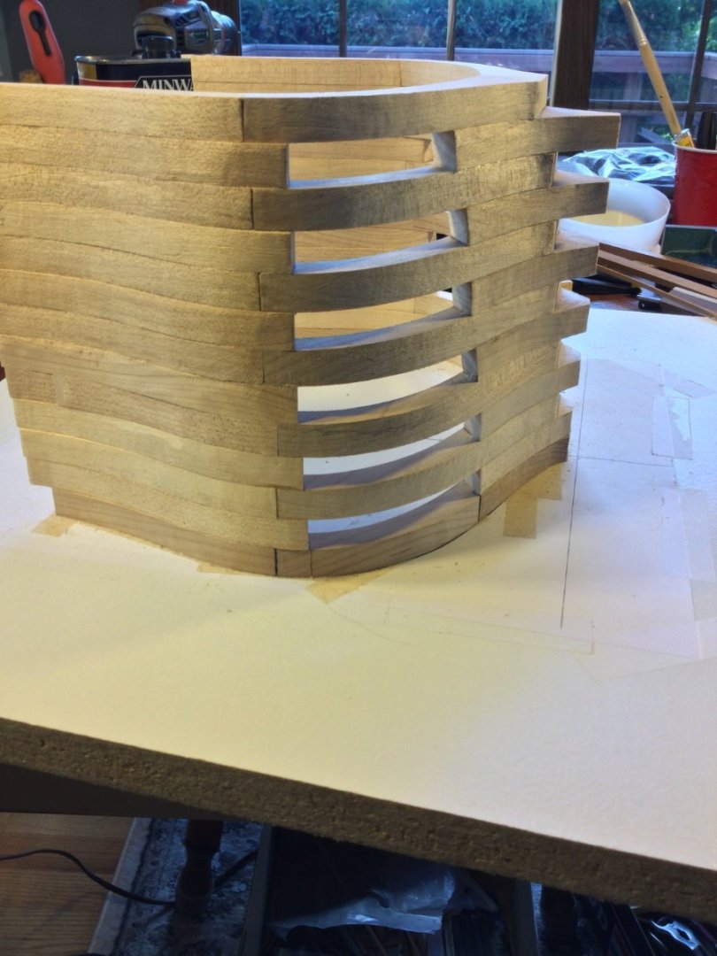
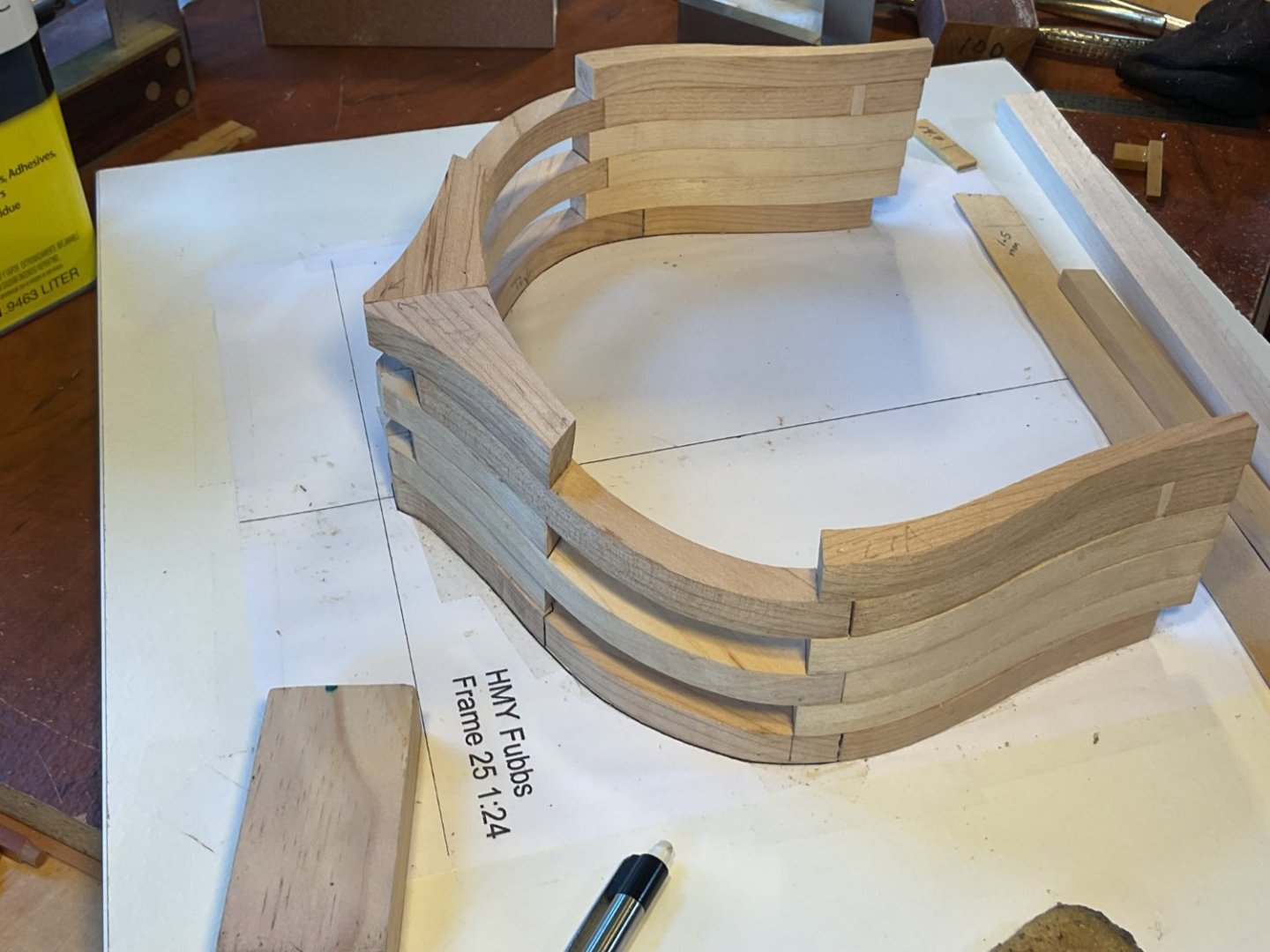
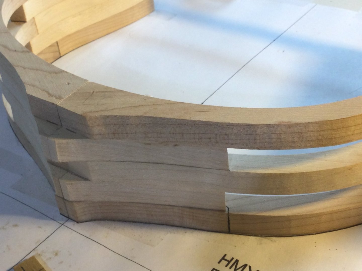
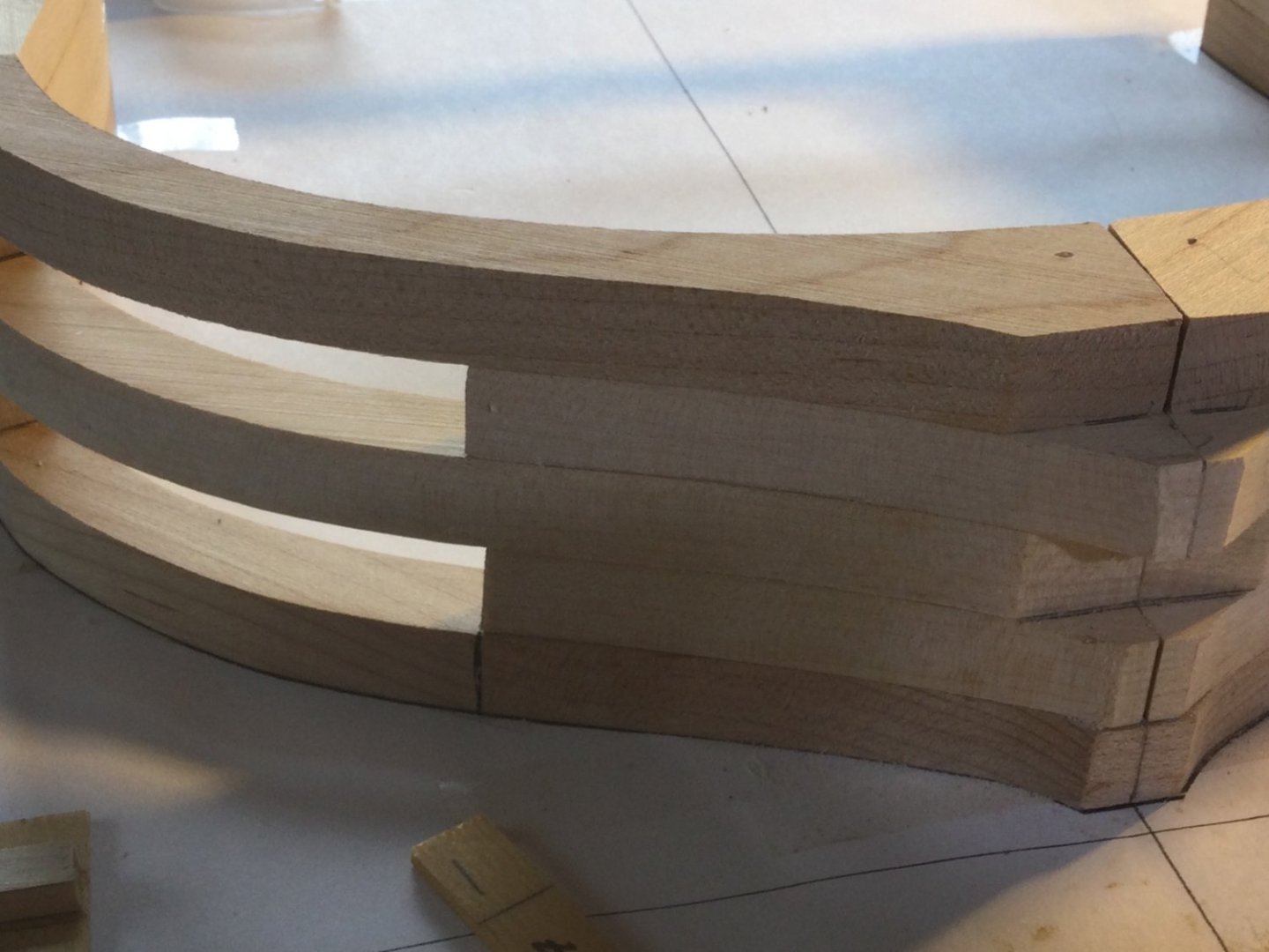
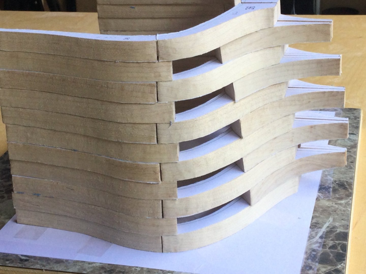
I finished beveling all the frame parts from 25 through 36. I will probably have to wait until the aft section is glued up to fit frame 36A because of the changes made when the prototype was being build. Here are some shots of frames 31 through 36, stacked up but not glued. You can see the lines of the hull taking shape,


-
DocBlake reacted to a post in a topic:
HMY Fubbs 1682 by Mike 41 - FINISHED - Weasel Works – Stern Section – 1:24
-
DocBlake reacted to a post in a topic:
HMY Fubbs 1682 by Mike 41 - FINISHED - Weasel Works – Stern Section – 1:24
-
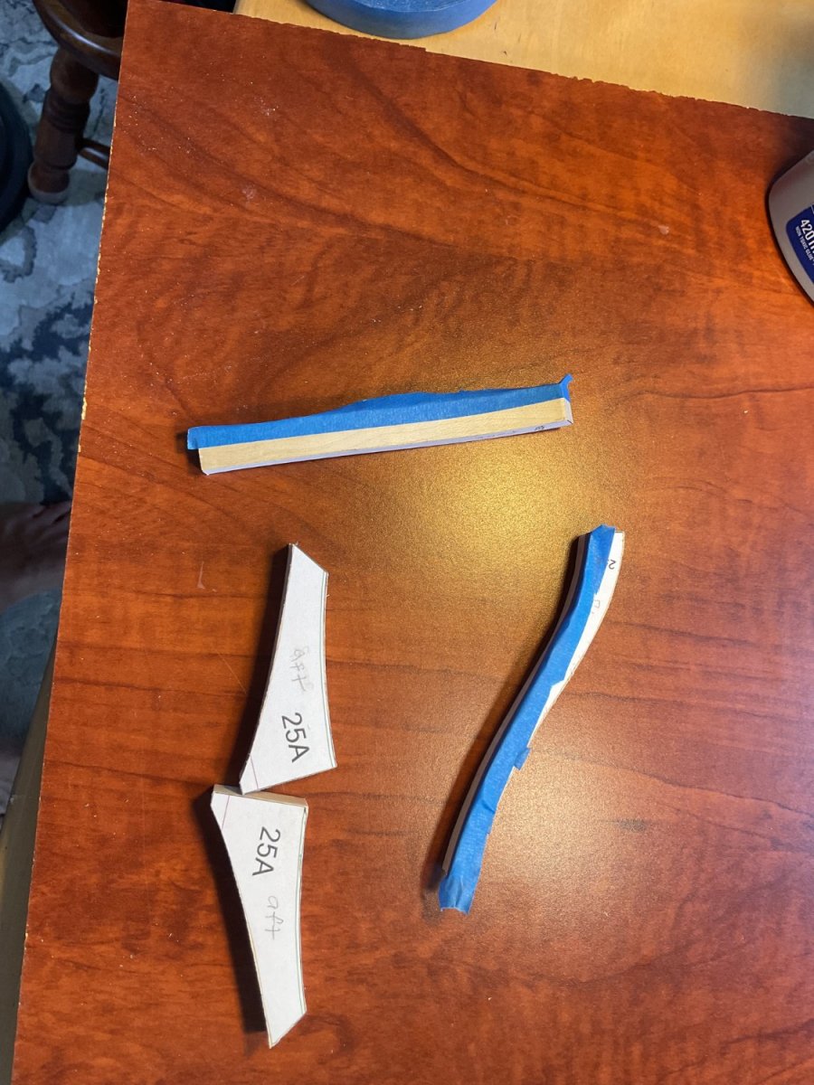
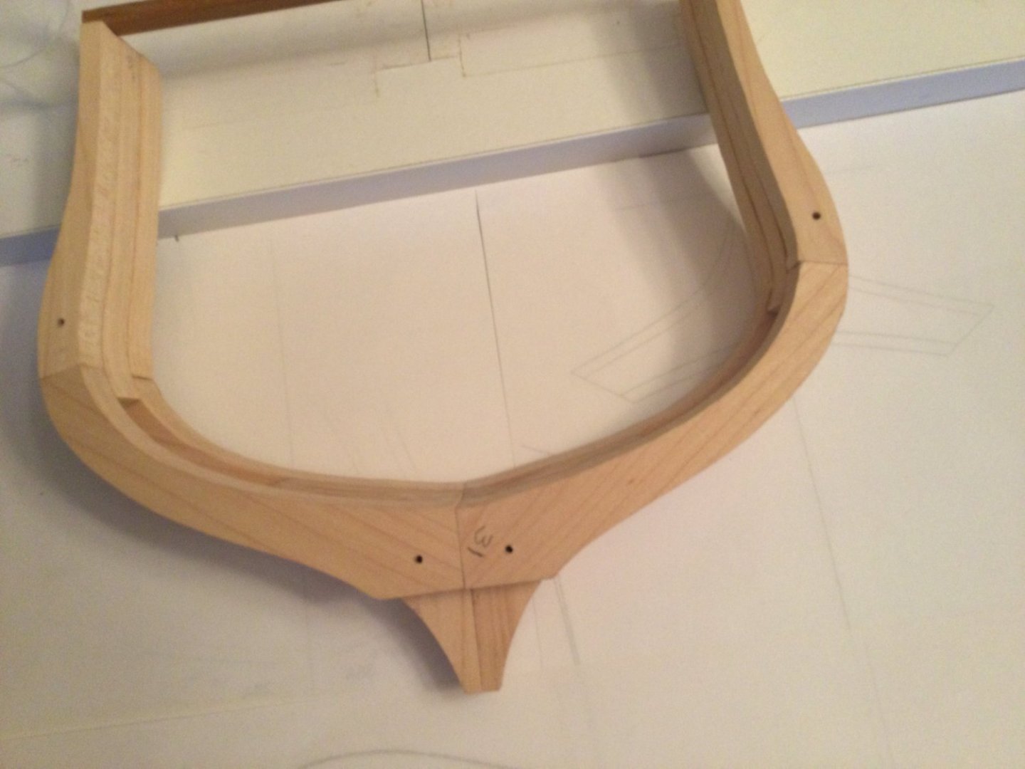
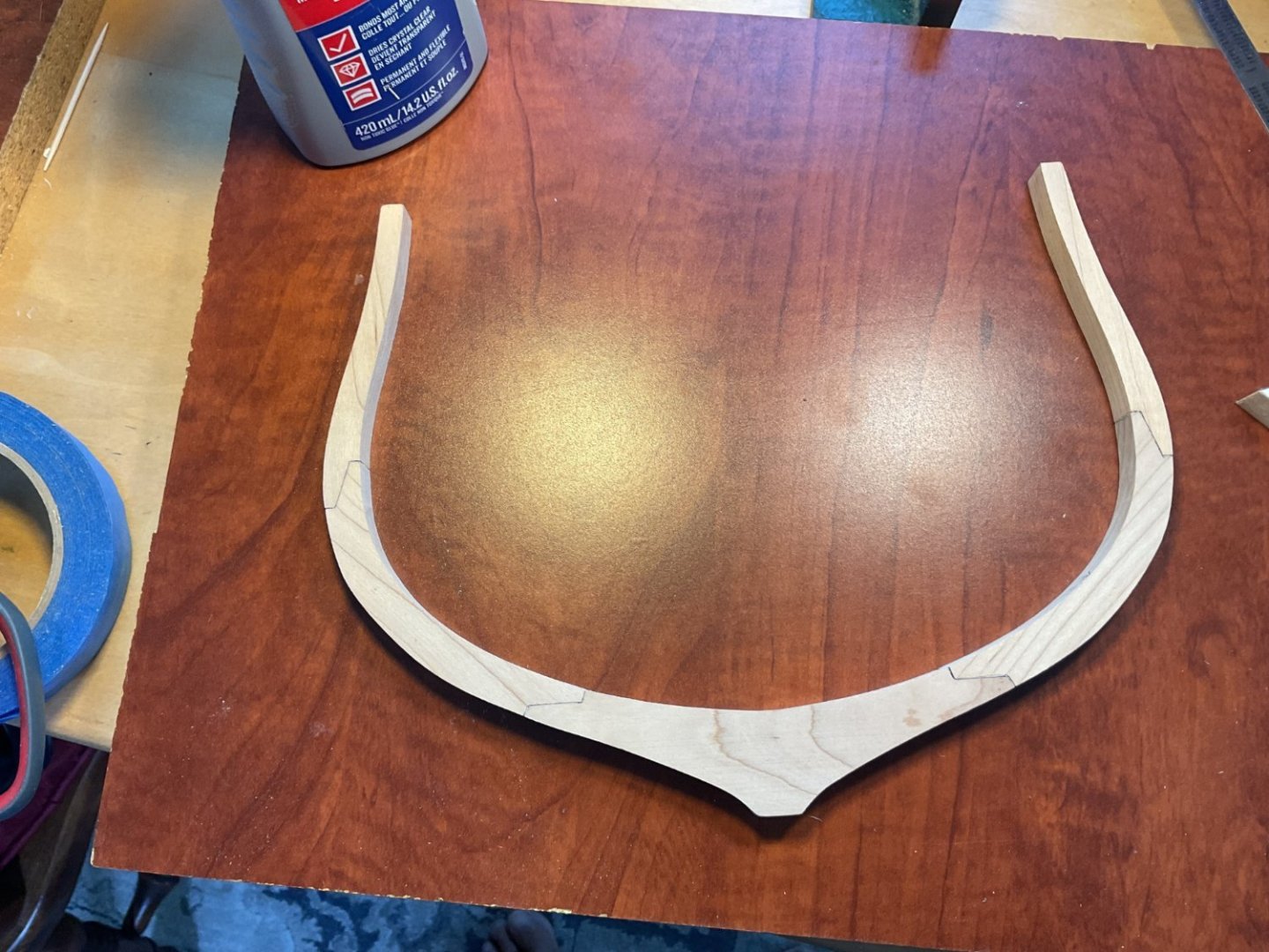
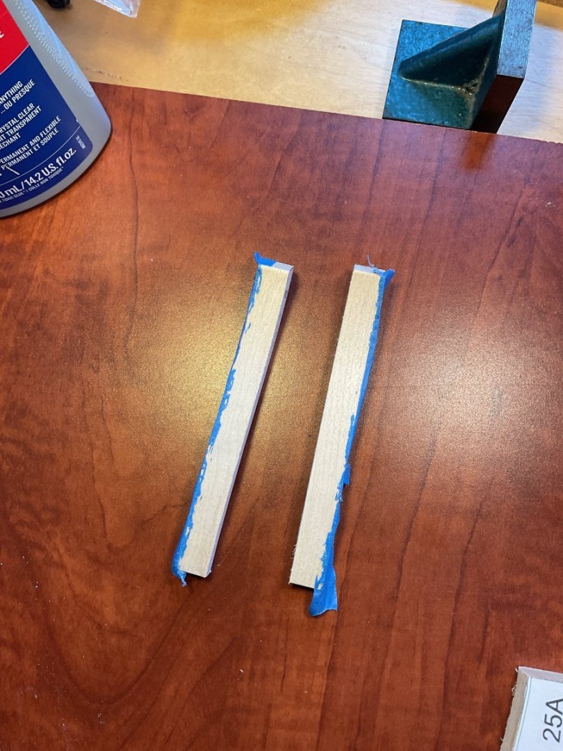
Thanks for looking in, guys! I began the actual construction of the model by assembling frame 25. This is the fore-most of the frames and the only one whose cross section is visible. Originally designed with butt joints, these were changed to scarf joints which more accurately reflect shipbuilding conventions of the time. I enhanced the scarfs with a little flat black acrylic paint. The bevels on frame 25 are infinitesimal. I didn't pre-bevel the parts. That can easily be done after the hull is glued together. Next came frame 25A. The bevels on the top timbers especially are very subtle. Oddly, these small adjustments are harder than the big angles we'll encounter further aft. I used a Dremel with a 1/2" drum and coarse sand paper. The problem here is that in forming the bevel. it's easy to take too much off near and up to the the non-beveled edge, making a rounded surface. To prevent that I put some painters tape on the final 3/16" of the surface I was sanding which warned me to be careful not to "round over" the surface. It worked well. As you can see, the bevel came right up to the unbeveled edge without actually crossing it. Laser char can work the same way.

-
Good tip, Allan. I’ll remember for the next time. Thanks!
-
Royal Yacht HMY Fubbs (1682-1781) – 1:24 Scale Stern Section by DocBlake This will be my build log for a 1:24 scale stern section of the HMY Fubbs. Fubbs was one of many Royal Yachts commissioned by King Charles II of England during the Stuart Restoration. The name derives from a nickname Charles had for his mistress, the Duchess of Portsmouth. Details of her history and drawings of the kit plans and contents can be found elsewhere. The reader is directed to build logs by Mike41 (https://modelshipworld.com/topic/34926-hmy-fubbs-1682-by-mike-41-weasel-works-%E2%80%93-stern-section-%E2%80%93-124/#comment-996763 The model will be built as a limited edition kit produced by Weasel Works. In all there were 10 kits and Mike Shanks' prototype produced. There are over 900 parts in each kit, with some options for personalizing the builds (such as choice of timber for framing, etc.) Even with all the frame parts removed from their billets to save shipping costs, my kit weighed in at 13 pounds! Weasel Works a group of modelers with different interests and skills We are not a business at all. We are exploring what modern technology can bring to the table in model ship building. There are ten kits produced, as well as Mike Shank's prototype. We have no plans to sell or produce any more. Our goal is to produce an attractive model that's fun to build. We are not historians nor naval architects, and accordingly, have allowed ourselves some artistic license. Although based on the 1682 version of Fubbs, details from other points in her history have been incorporated into the model, and her framing is not historically accurate, but does reflect well her hull's shape. Although the Great Cabin's floor cover was most probably painted canvas, we felt the parquet floor was a nice addition to the model, so we kept it in. The transom/taffrail design is from later in her career. My frames are hard maple, cut out by CNC. Advantage: No laser char. Disadvantage: bevel lines not etched for the bevel, so each piece requires a template to be carefully cut out and rubber cemented to the frame piece, then bevelled then cleaned of residual paper and cement. Mind numbing. There are over 100 frame parts.