HOLIDAY DONATION DRIVE - SUPPORT MSW - DO YOUR PART TO KEEP THIS GREAT FORUM GOING! (Only 13 donations so far - C'mon guys!)
×


ir3
-
Posts
336 -
Joined
-
Last visited
Content Type
Profiles
Forums
Gallery
Events
Everything posted by ir3
-
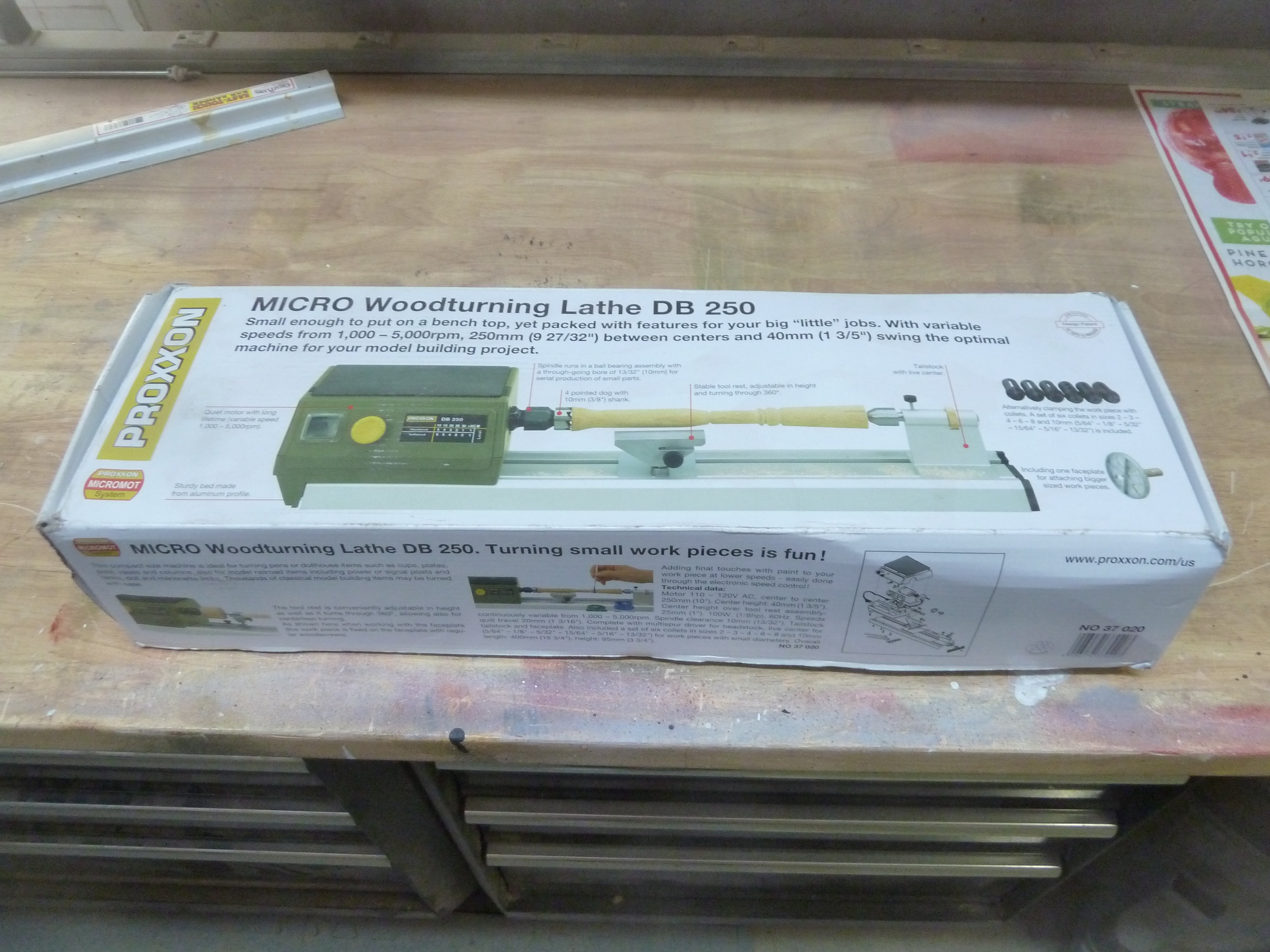
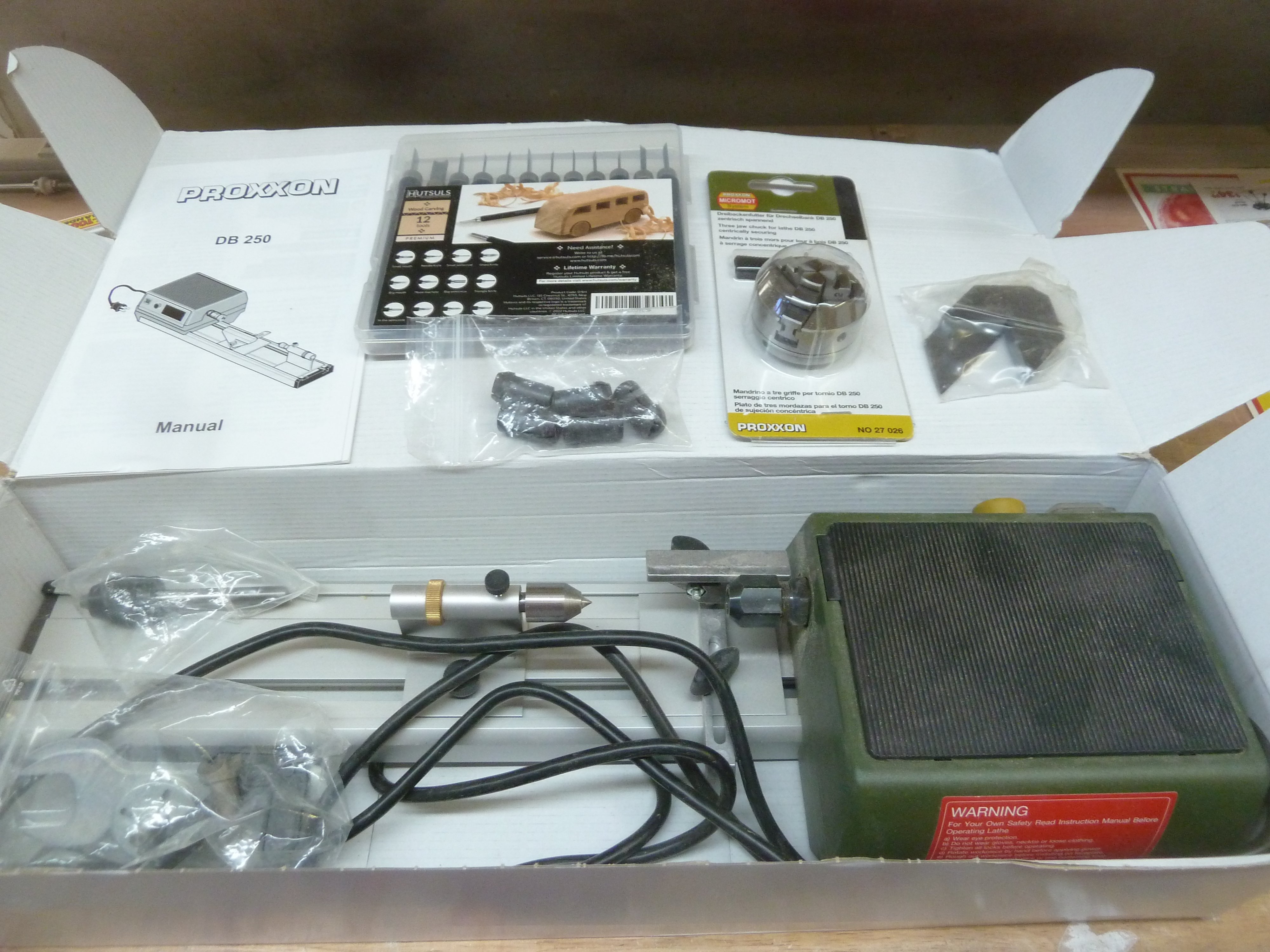
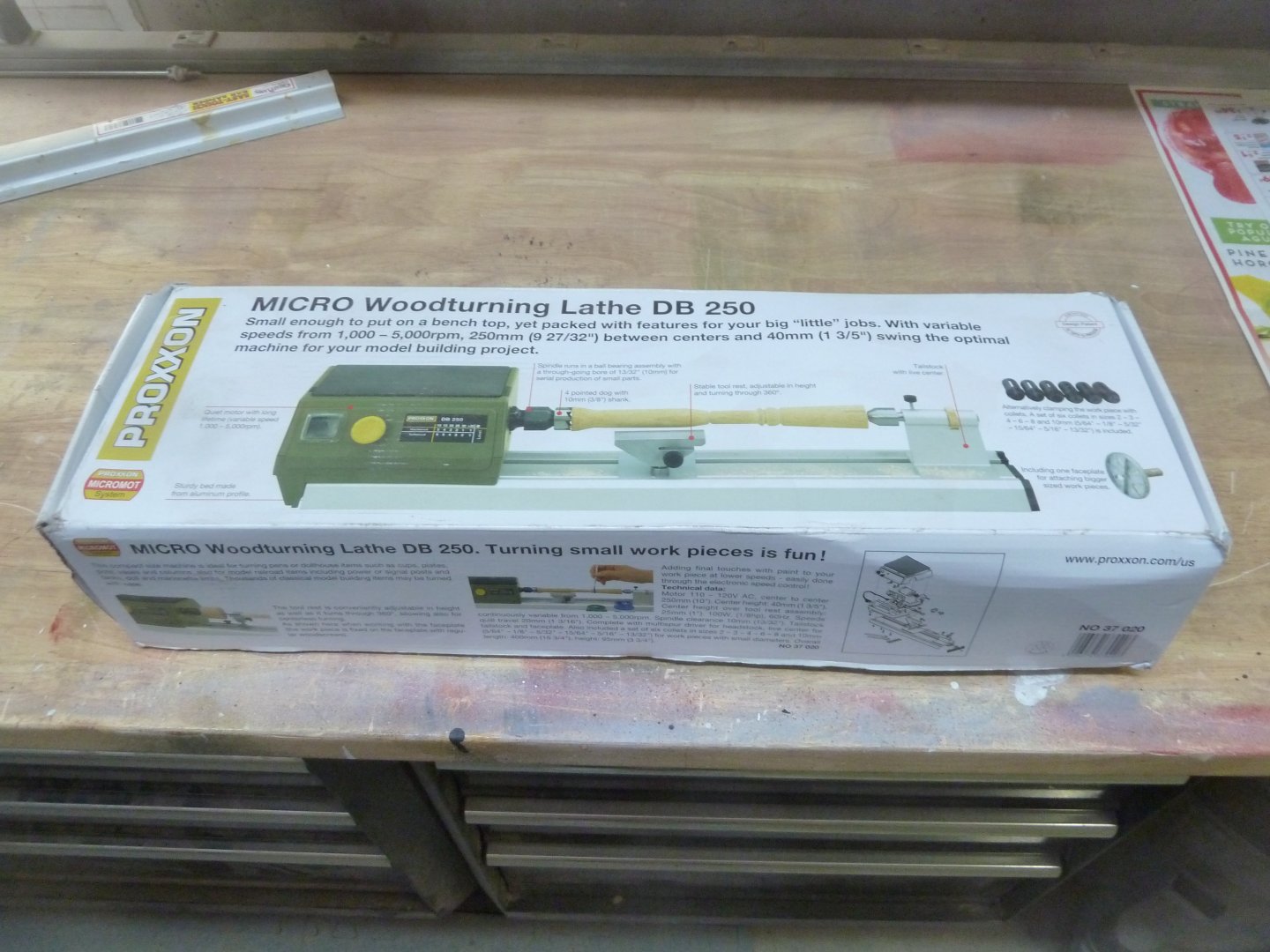
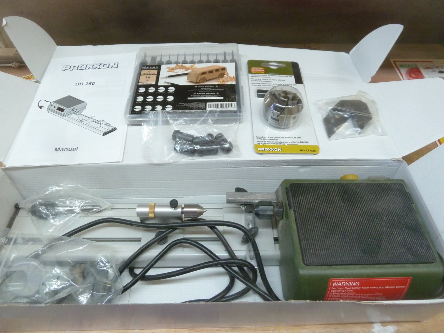
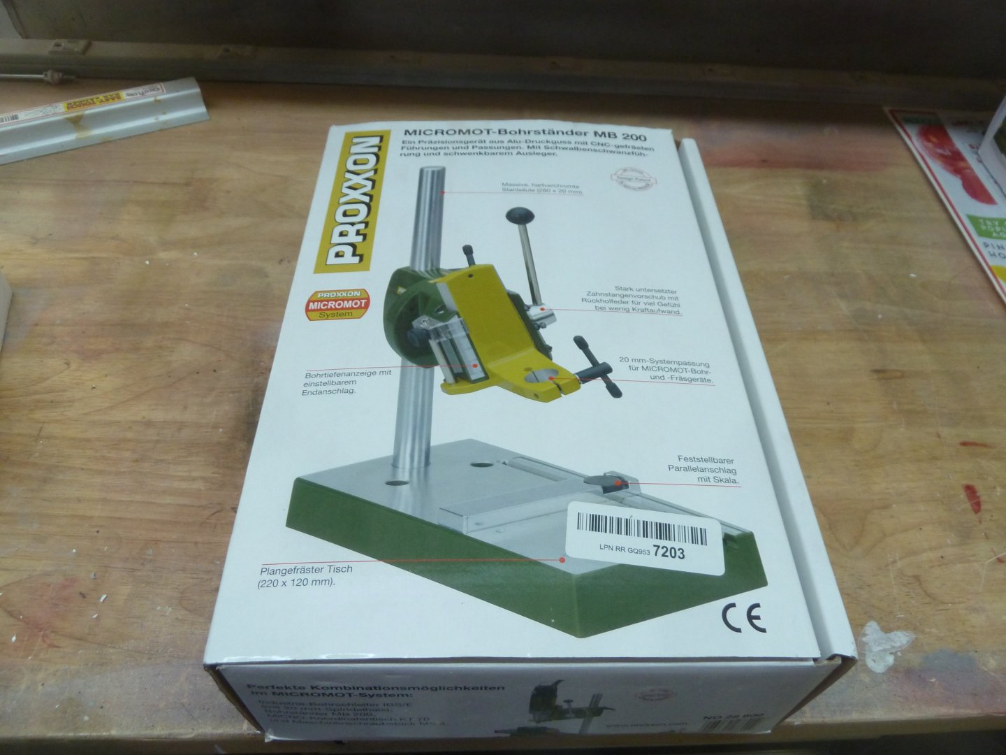
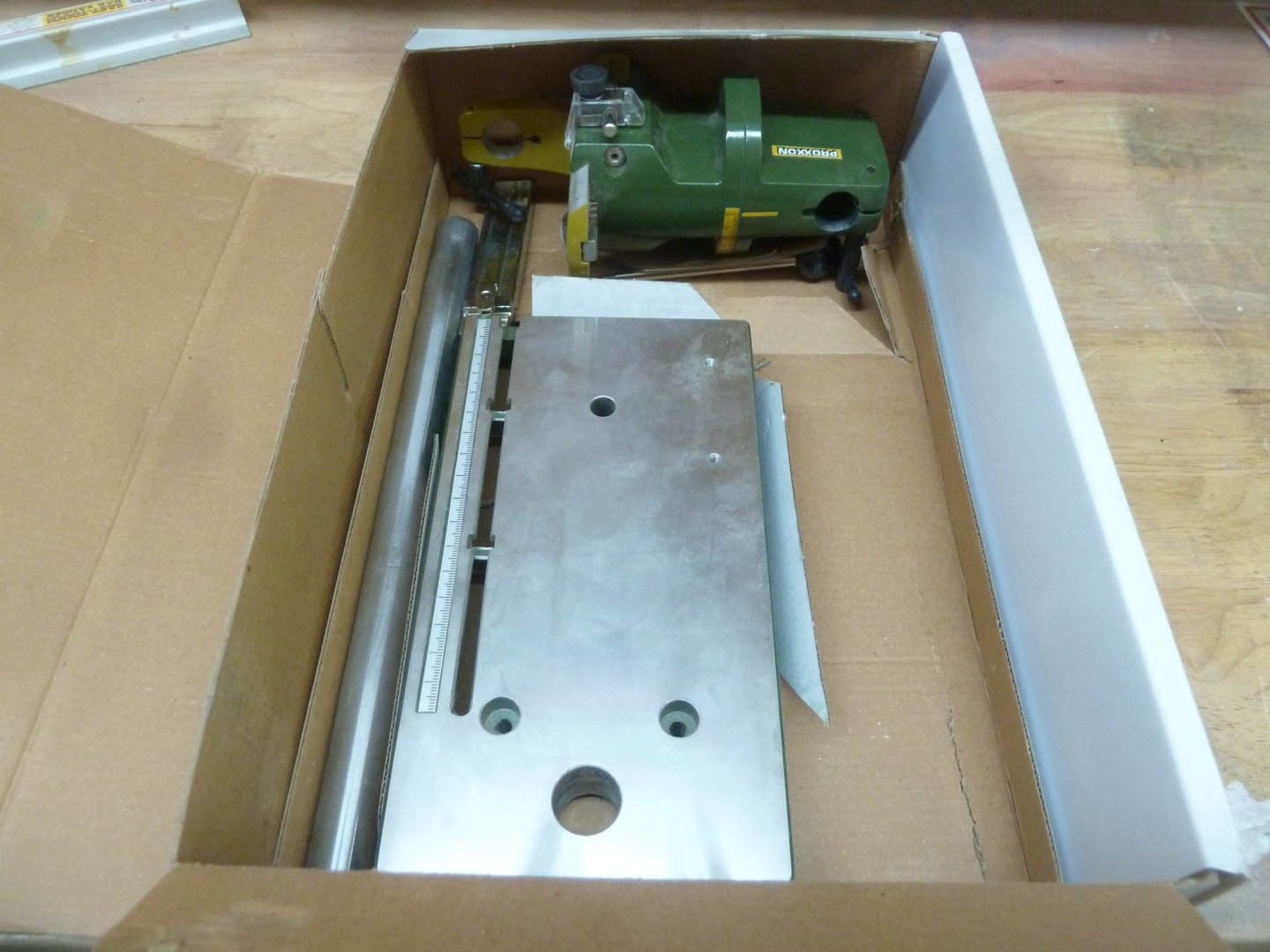
Up for sale is a Proxxon Woodturning Lathe DB250 plus extras. The Lathe come with the Proxxon 3-Jaw Chuck, wood turning chisels, and a MicroMark center. $245 shipped CONUSA. -- PROXXON LATHE HAS BEEN SOLD -- Also, up for sale is a Proxxon Micromot Drill Stand. $80 shipped CONUSA. Both items used sparingly. PayPal preferred and thanks for looking.
-
- 1
-

-
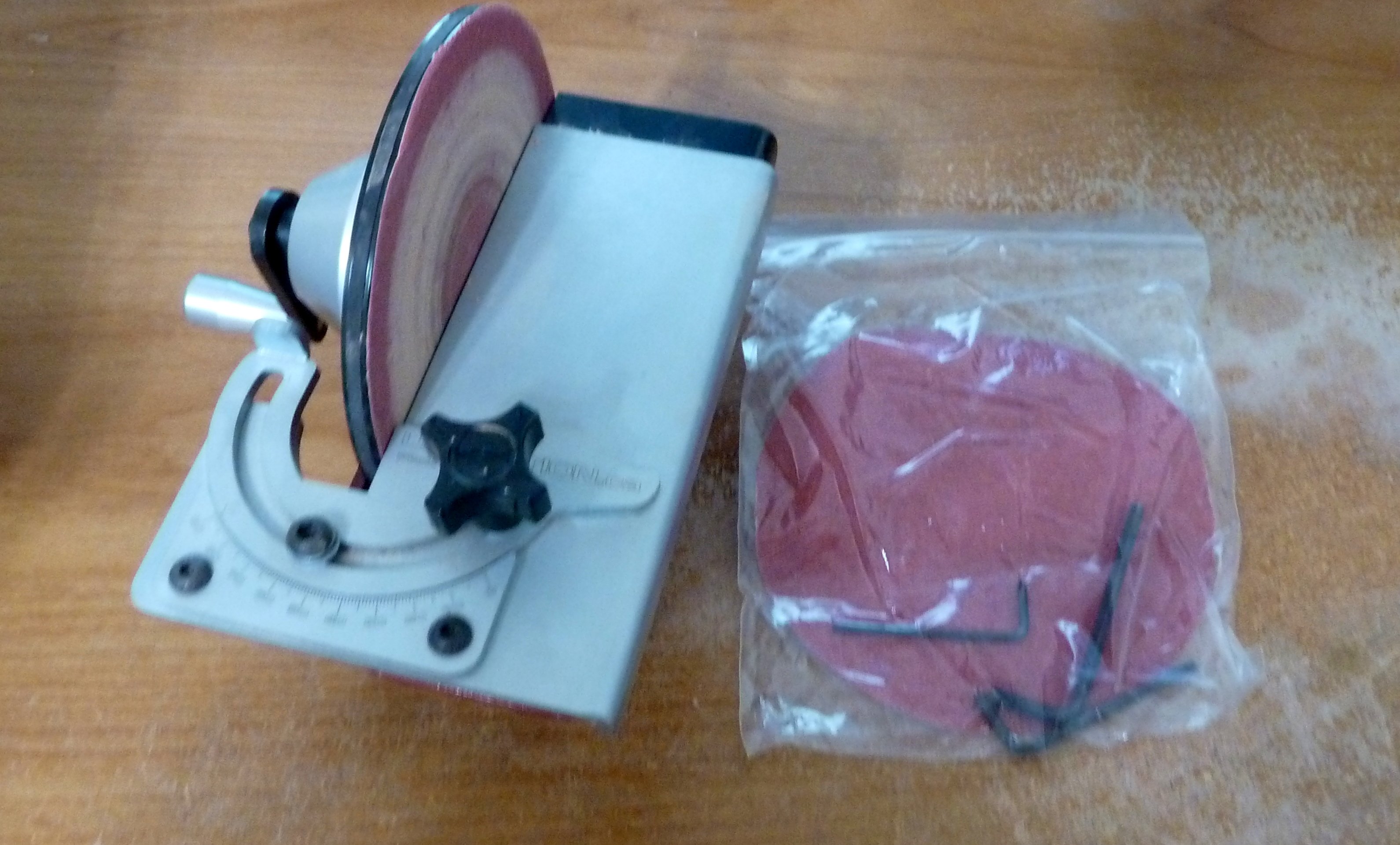
Up for sale is a Ultimation Chopper and Ultimation Sander in excellent condition, used sparingly. Asking $250 plus shipping for the pair. I would prefer to sell the pair but individually, the Sander is $150 plus shipping and the chopper is $125 plus shipping. Shipping in the USA is preferred. Thanks for looking. Sorry about the poor photography. PayPal preferred.


-
- 2
-
-
If interested in a Ropewalk, follow this link: https://fb.watch/zQsO82nD-P/ Very impressive.
- 1 reply
-
- 2
-
-
I have a question early in the build. When the printed lower deck is installed, the gratings assembled, and the ladder is built, should WOP or some other coating be put on or just leave the wood bare. Thanks, Iran Ausley
-
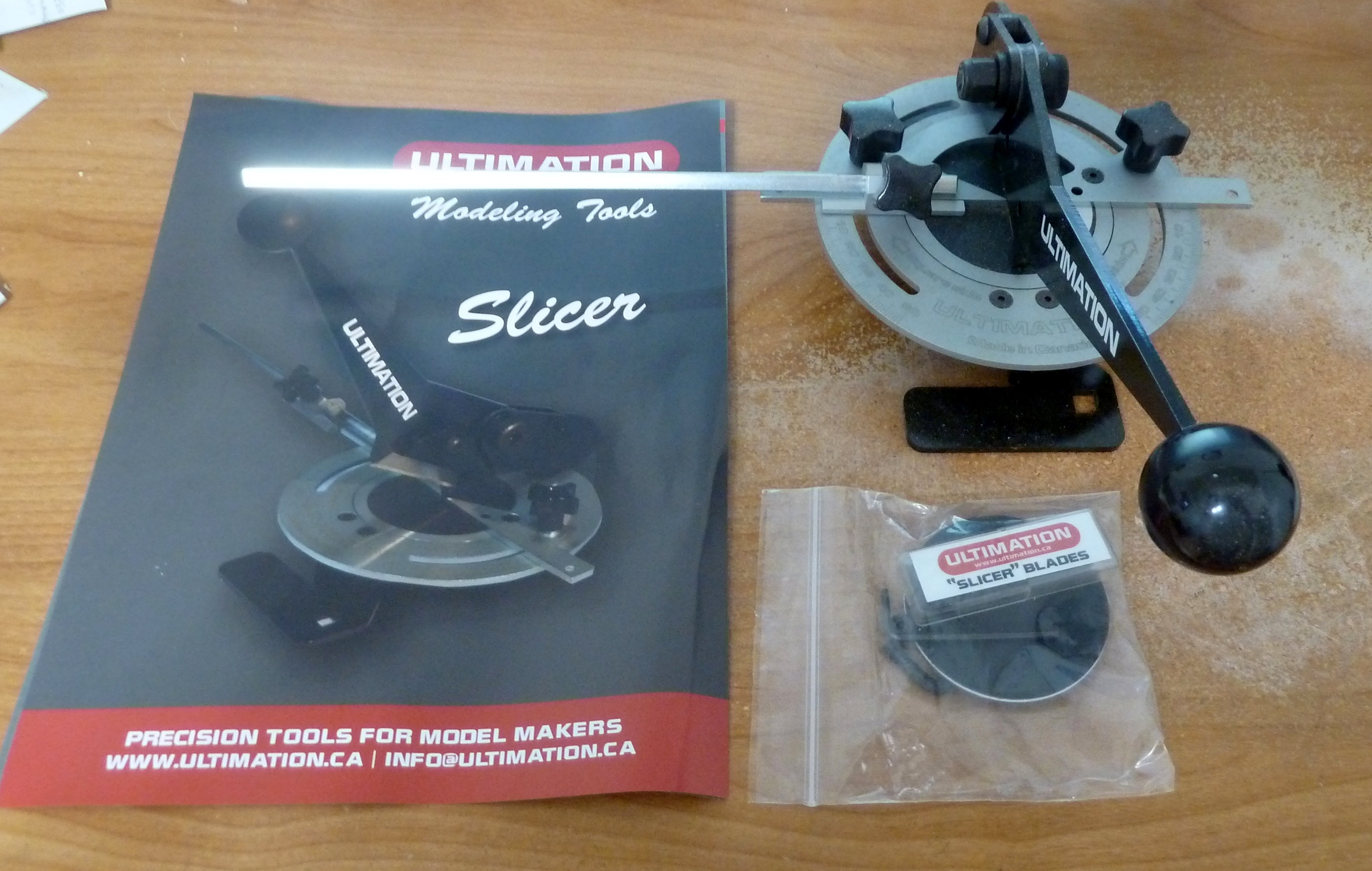
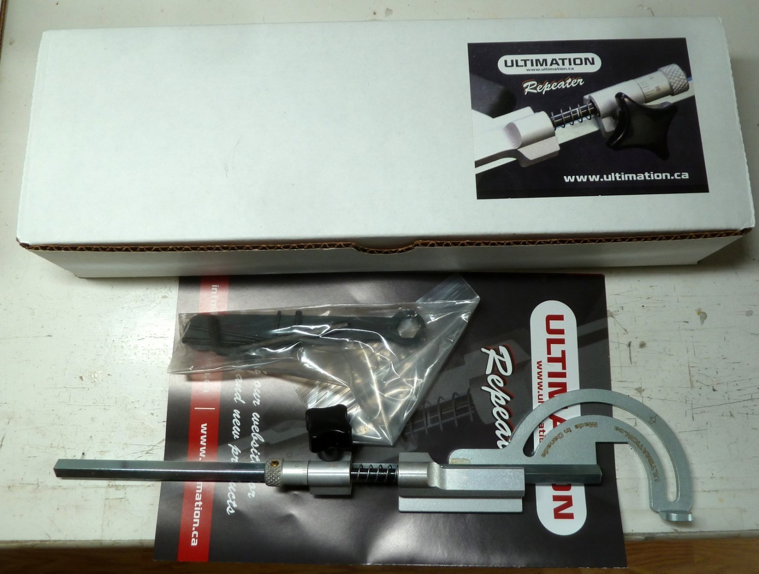
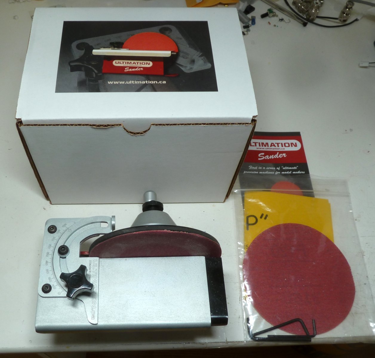
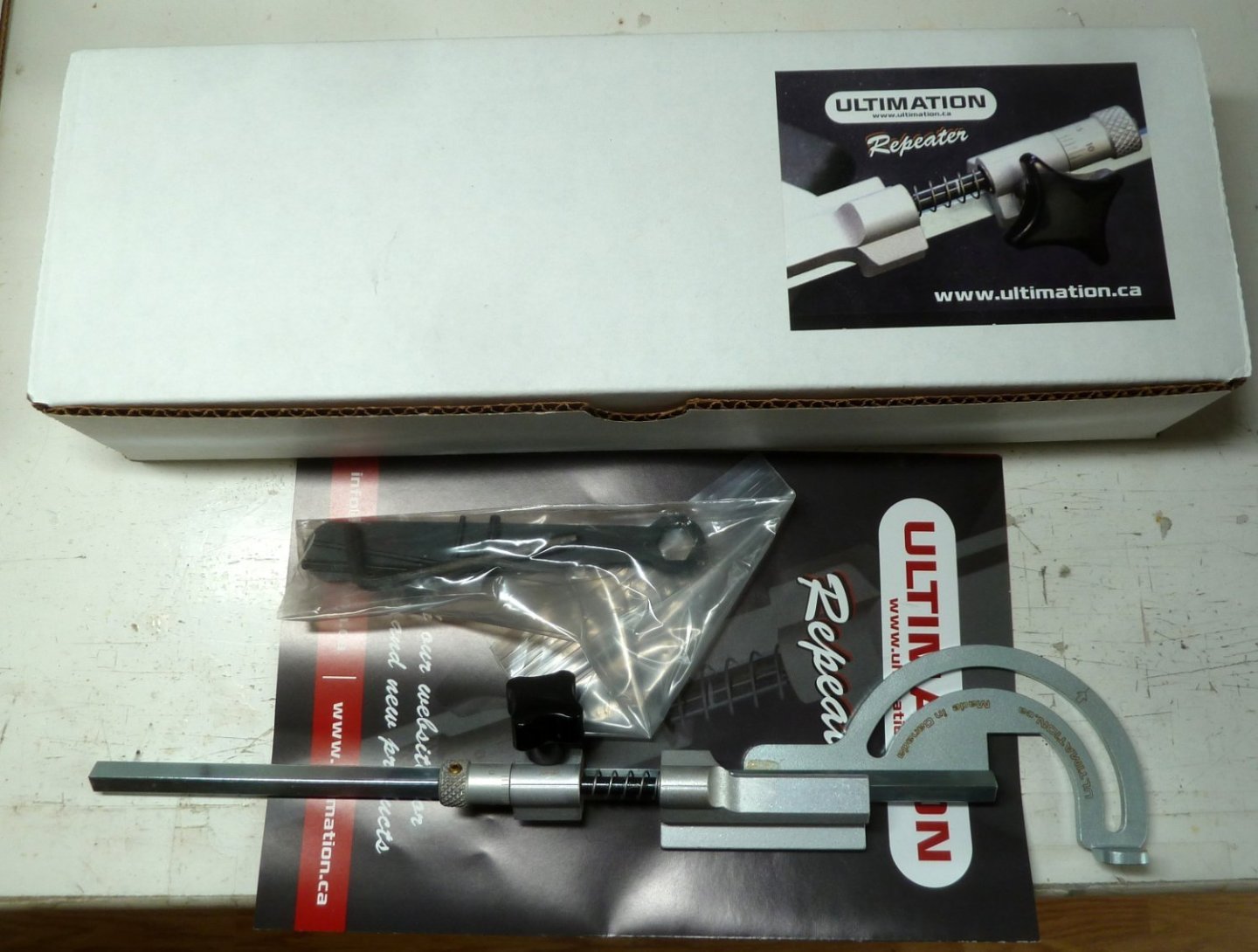
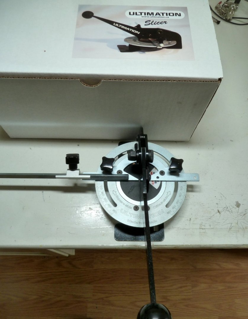
I am parting with my shop tools and am starting with Ultimation Sander, Sander Repeater, and Slicer. The Sander and Slicer have been used sparingly and are in perfect condition. Asking $125 plus shipping for the Slicer and $240 plus shipping for Sander with Repeater. $350 plus shipping for both. More to follow. Please ask questions and thanks for looking.

- 1 reply
-
- 3
-
-

-
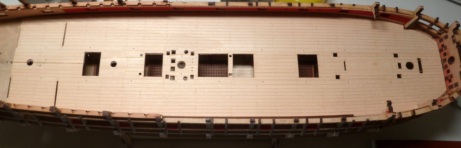
The deck is installed. A few minor areas needing repair but at least in place. I experienced most of the glitches pointed out in earlier posts. Now to move on. Thanks for all of the suggestions.
-
Thanks for all the input on handling the installation of the Gundeck. Much appreciated.
-
I will do that. Thanks for the suggestion.
-
It could be anything. Wood too dry, a flaw in the grain. Chris suggested scribing a line down the middle to help prevent a crack while bending the Gundeck Pattern. Of course, I could have been a bit aggressive. In any case, once the glue dries, I will try again.
-
Thanks James, easier said than done. I now have a crack going halfway down the deck from the stern. When flexing the deck to set it down one is pretty lucky if the deck doesn't split. So, now to repair the crack and try again. Easily said on paper but not so easy to accomplish.
-
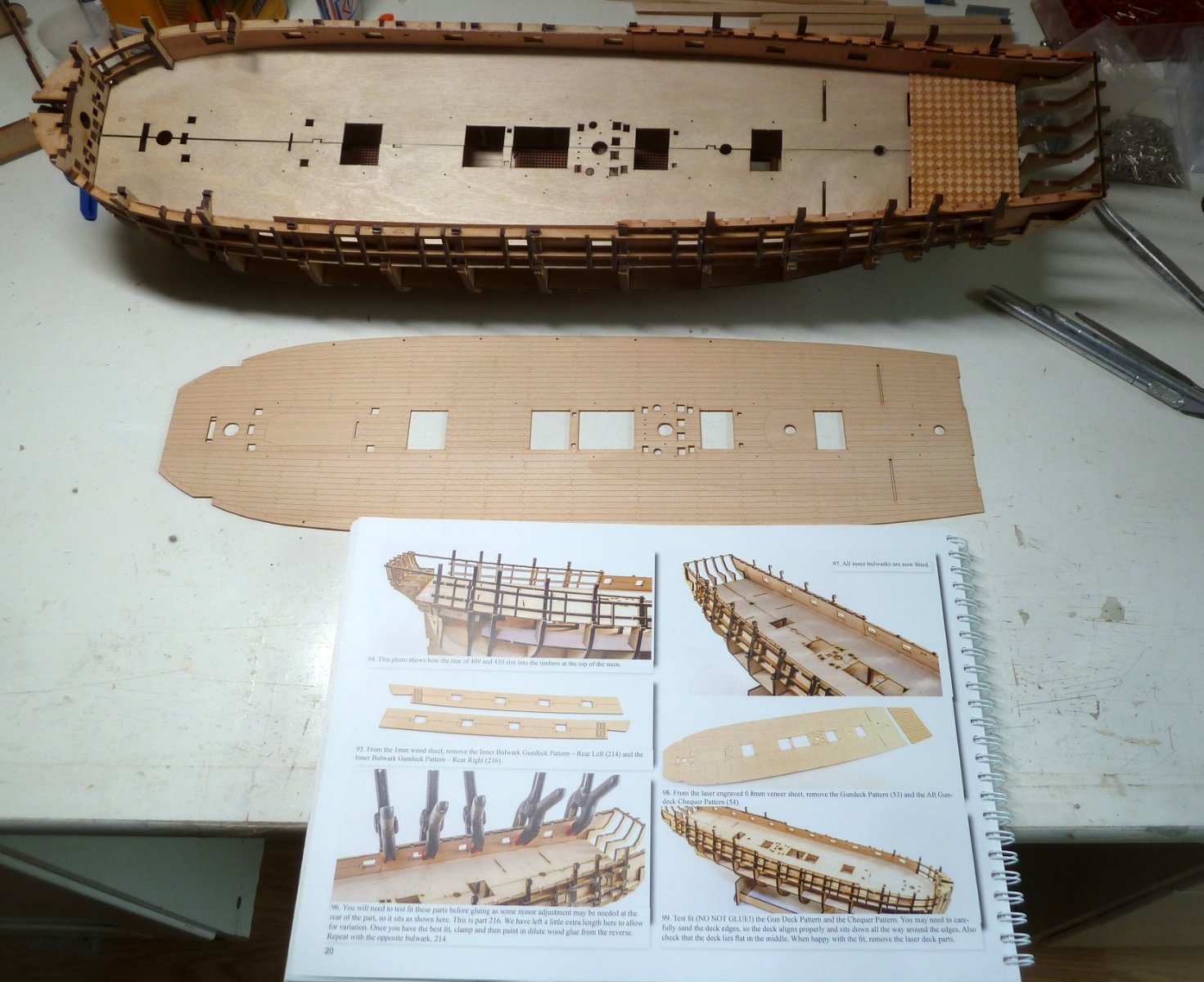
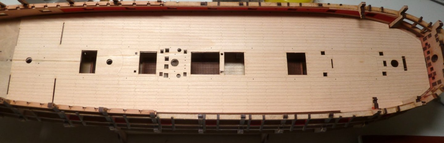
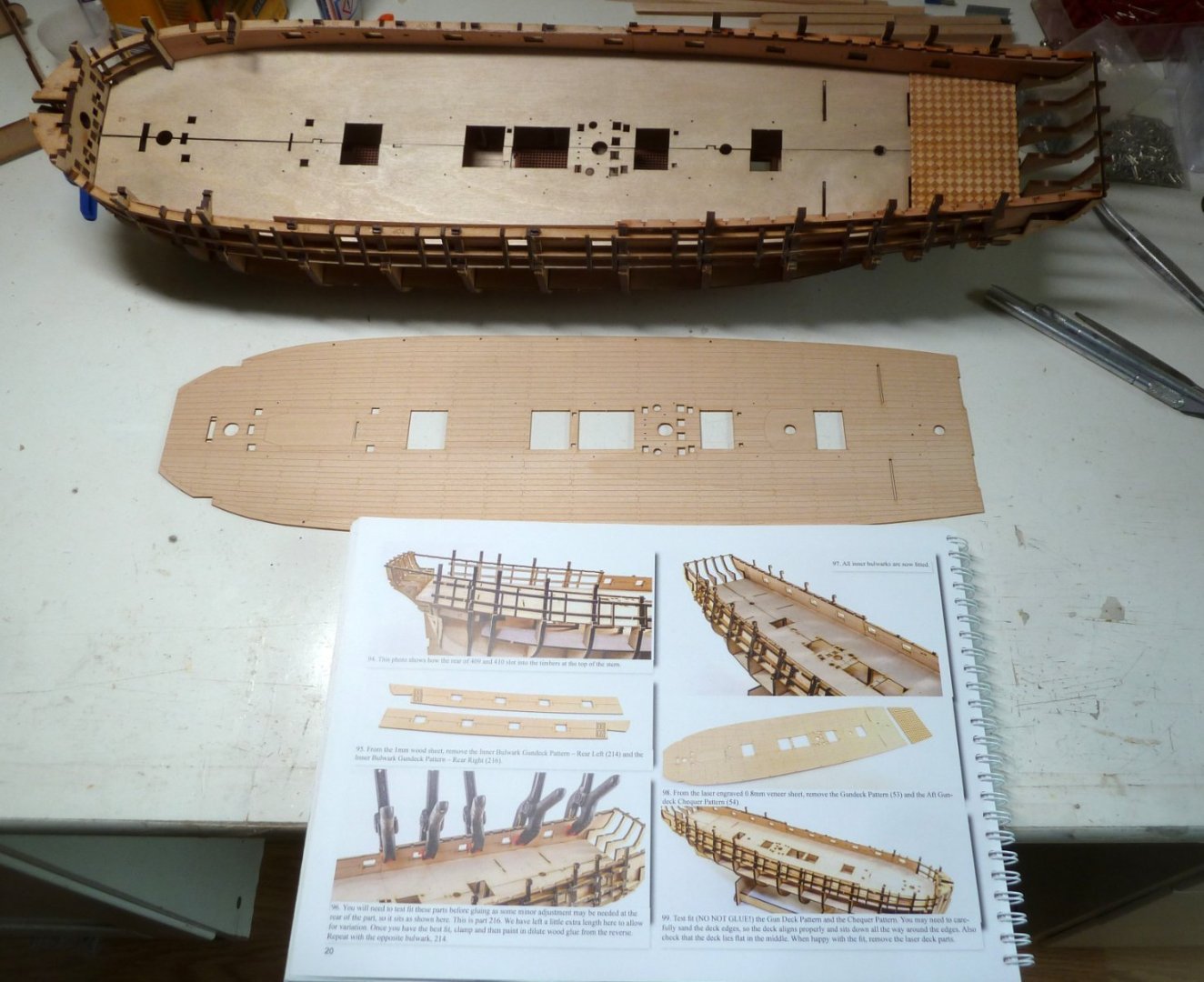
I am at step 99 in the builder's guide. I didn't start the thread from step 1 as this has been covered by several of the modelers doing this build. I waited until I ran into a problem and need to get some advice. I fitted the checkerboard pattern but when it came to the gundeck pattern, not sure how to test fit it. I am afraid to bend it so it can be dropped in. Once it is in, places it must be trimmed to fit will be evident but then how to get it back out again. Totally flummoxed. Any suggestions would be appreciated. Thanks in advance.
-
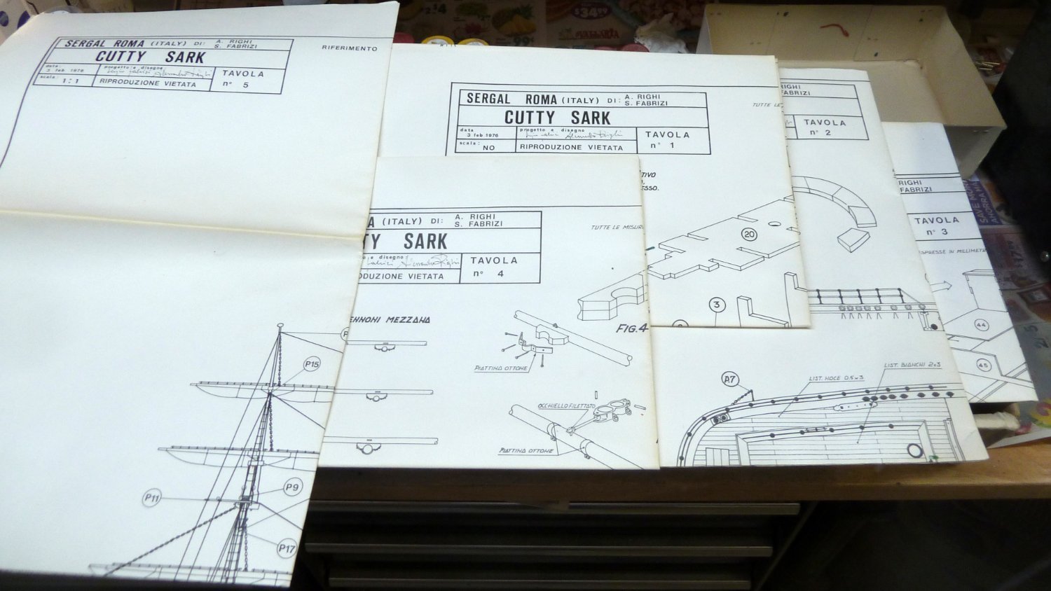
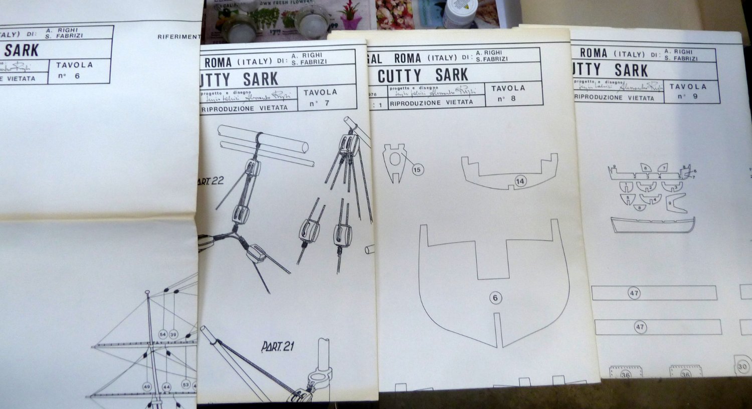
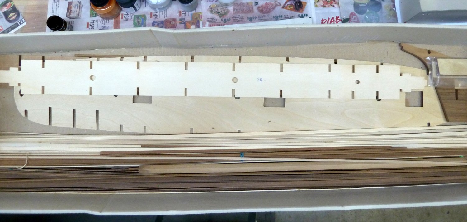
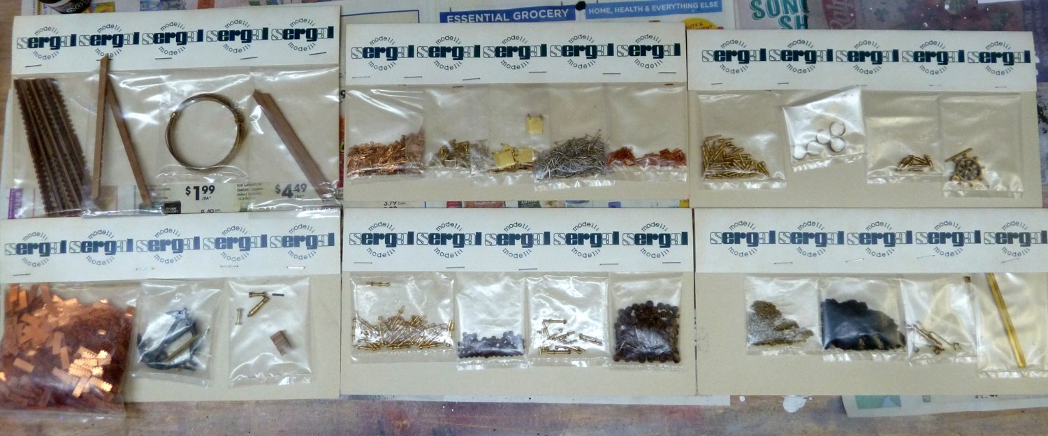
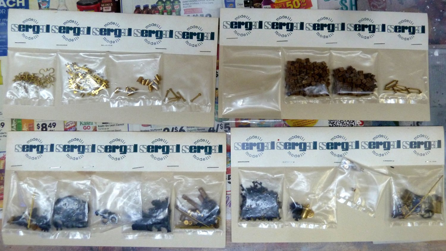
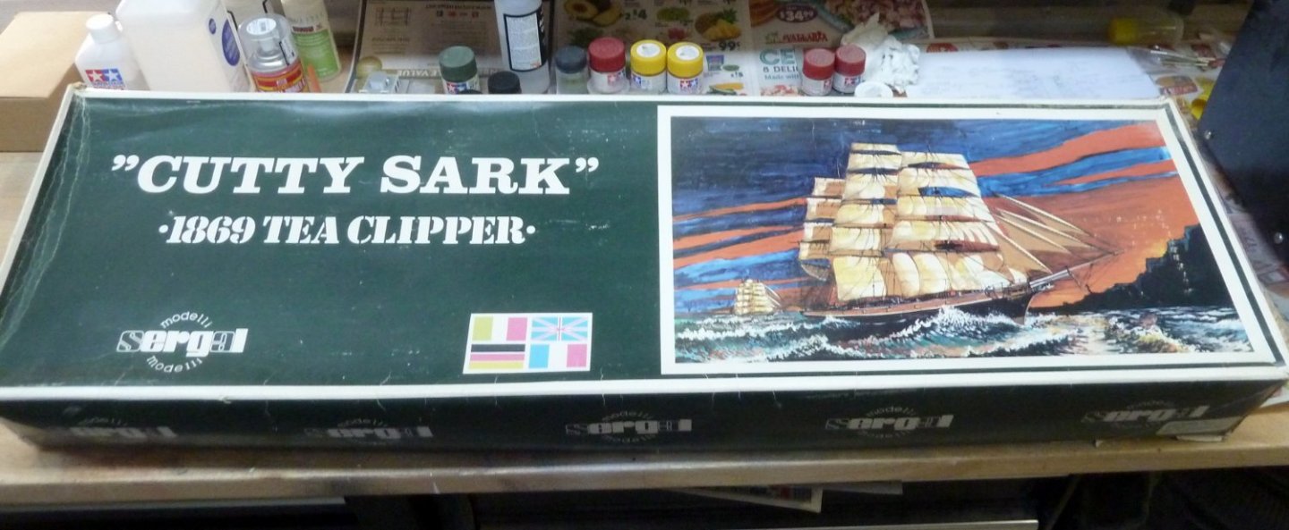
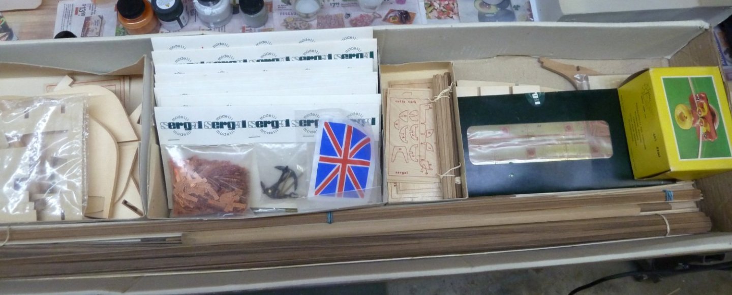
I am parting with a very old Sergal Cutty Sark kit. This kit is from the best of Sergal. There are 9 very detailed plan sheets. The stick wood, deck, and frames are excellent with no warpage, The fittings are exemplary and includes the copper plating for the hull. The decorations are cast and not photo etch. The Bulwarks are in PE and I will be happy to open the package and show the pieces if needed. I will include Lusci's book and Longridges 2-part, 1 volume book "Cutty Sark Last of the Tea Clippers". Asking $300 plus shipping CONUSA. If there is some interest outside of CONUSA, the kit box is 36" x 11" x 5" and weighs approximately 15lbs. You can calculate shipping from Postal Code 91307, USA. Please ask questions and thanks for looking.


-
- 1
-
-
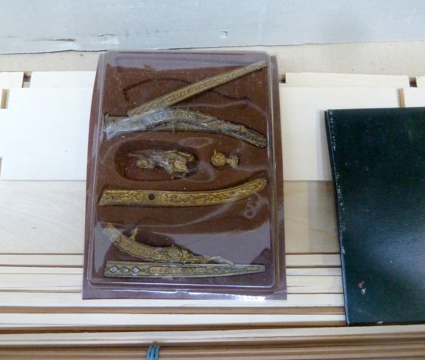
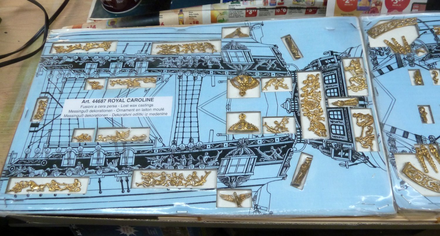
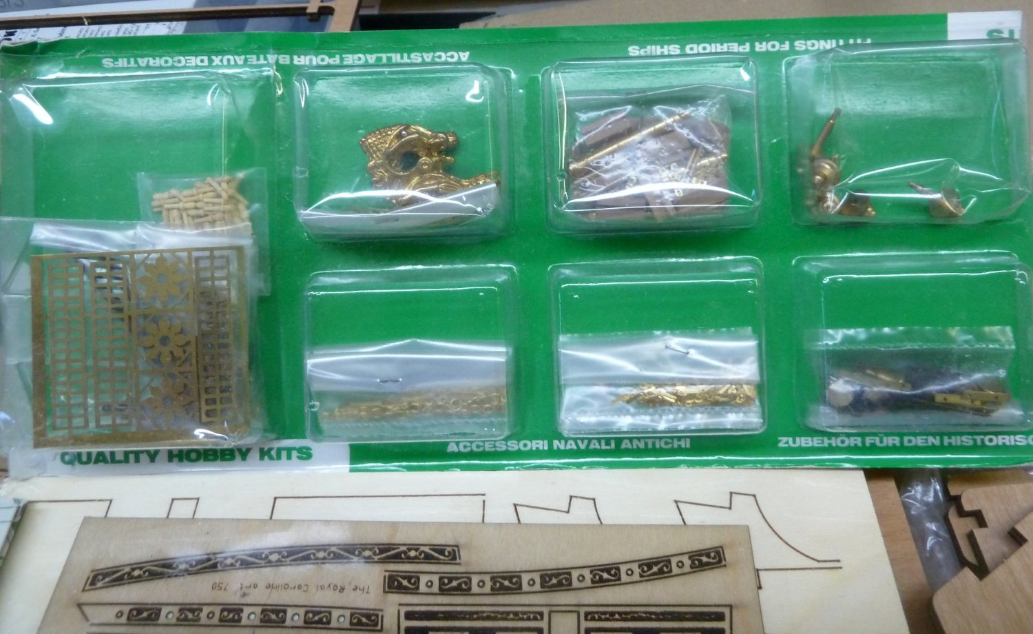
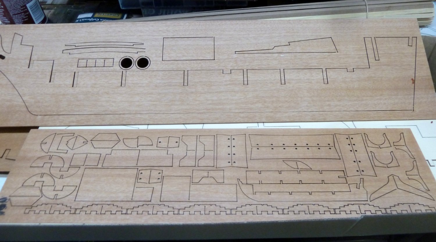
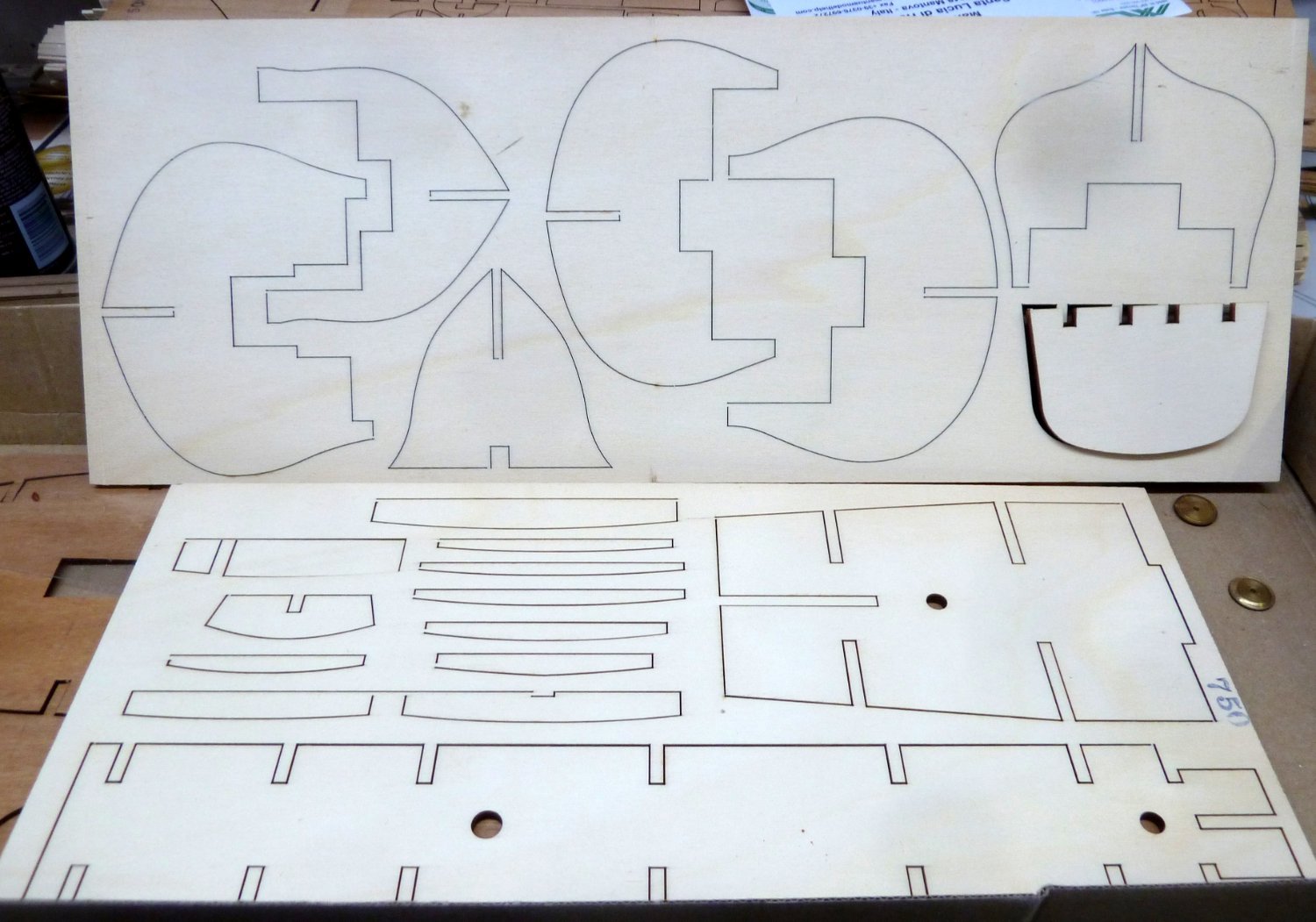
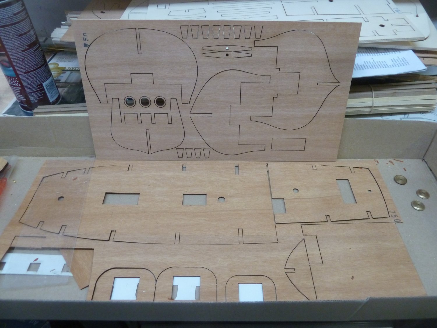
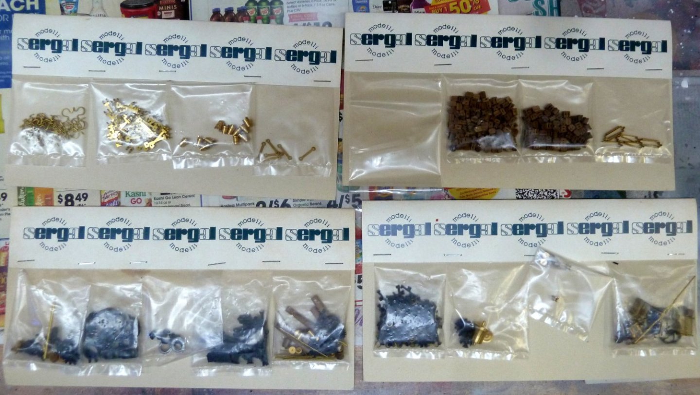
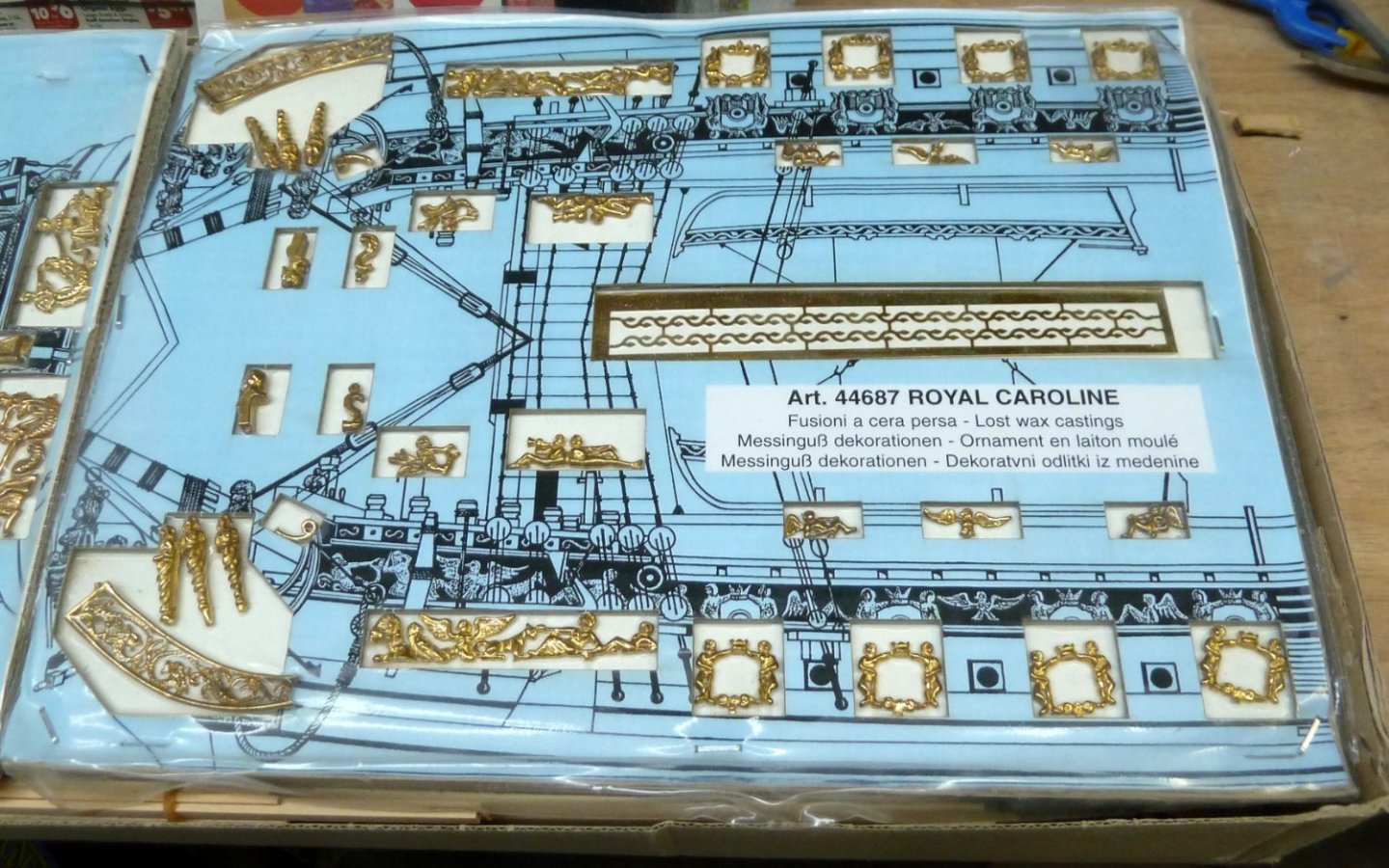
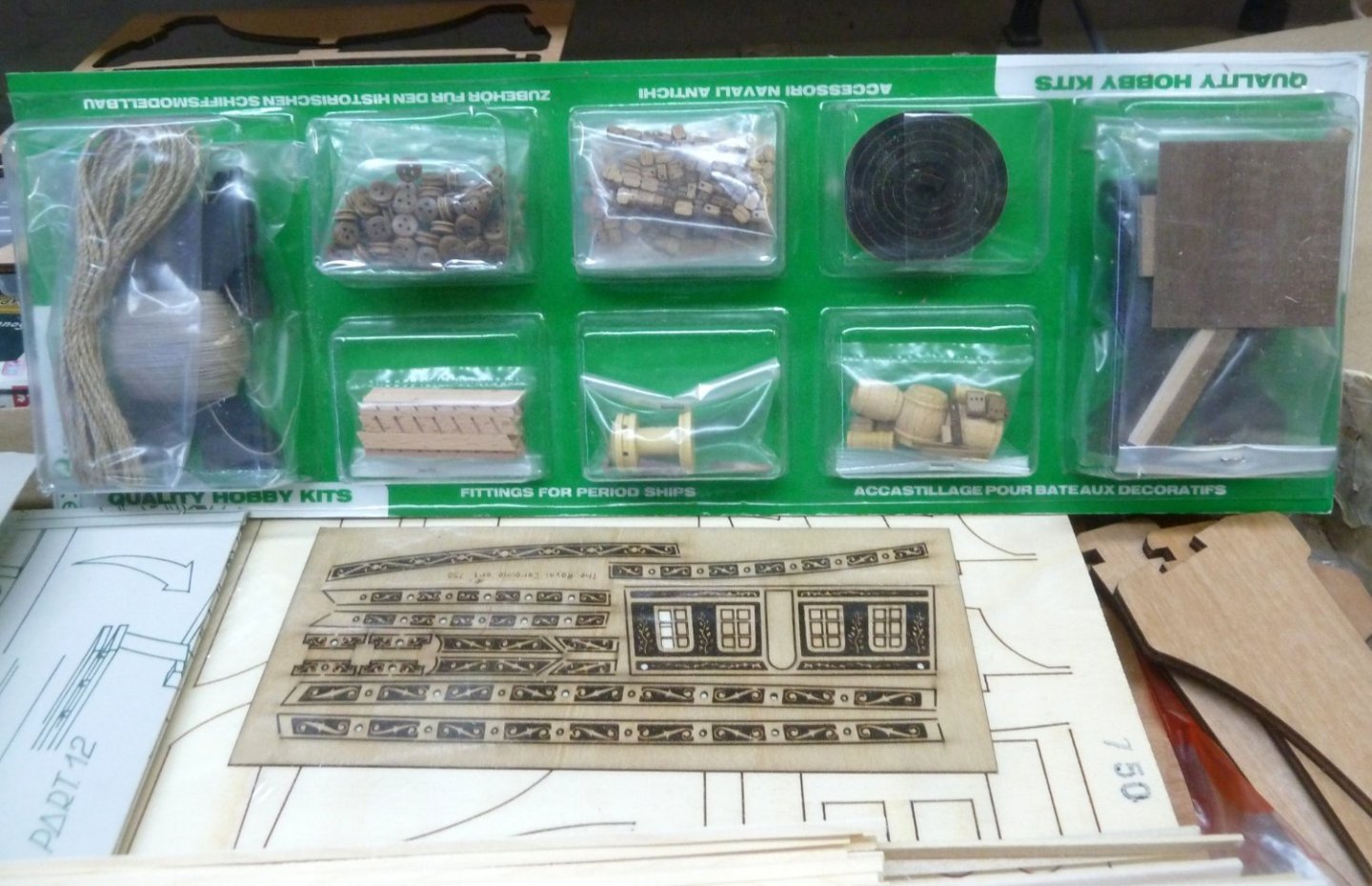
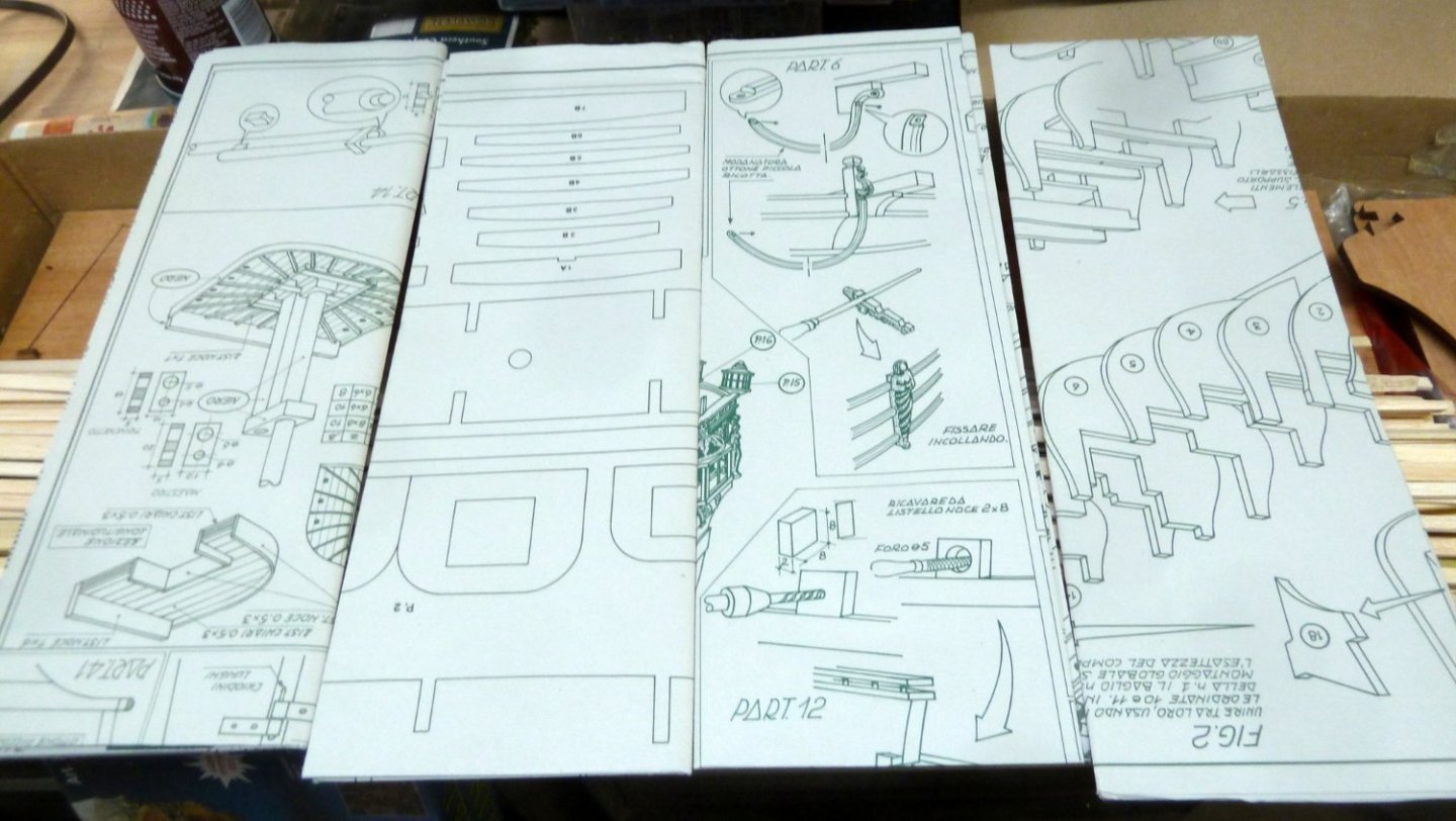
Earlier in the year I purchased the Panart 1:47 Royal Caroline kit from a fellow modeler. I have decided to stop working on wooden ship models and continue with my RC Electric and Steam powered boats. The kit was originally purchased from Model Expo in 2007 and is still in excellent condition with no warping of any of the wood as the pictures will show. I am asking $300 for the kit plus shipping. Instructions included but not in pictures. Note that some parts have separated from the die cut sheets. Questions welcomed and thanks for looking.


-
- 4
-
-
Part 2 still available. If still doing part 1 and interested, let me know.
-
Part 3 has been sold. Part 2 is still available.
-
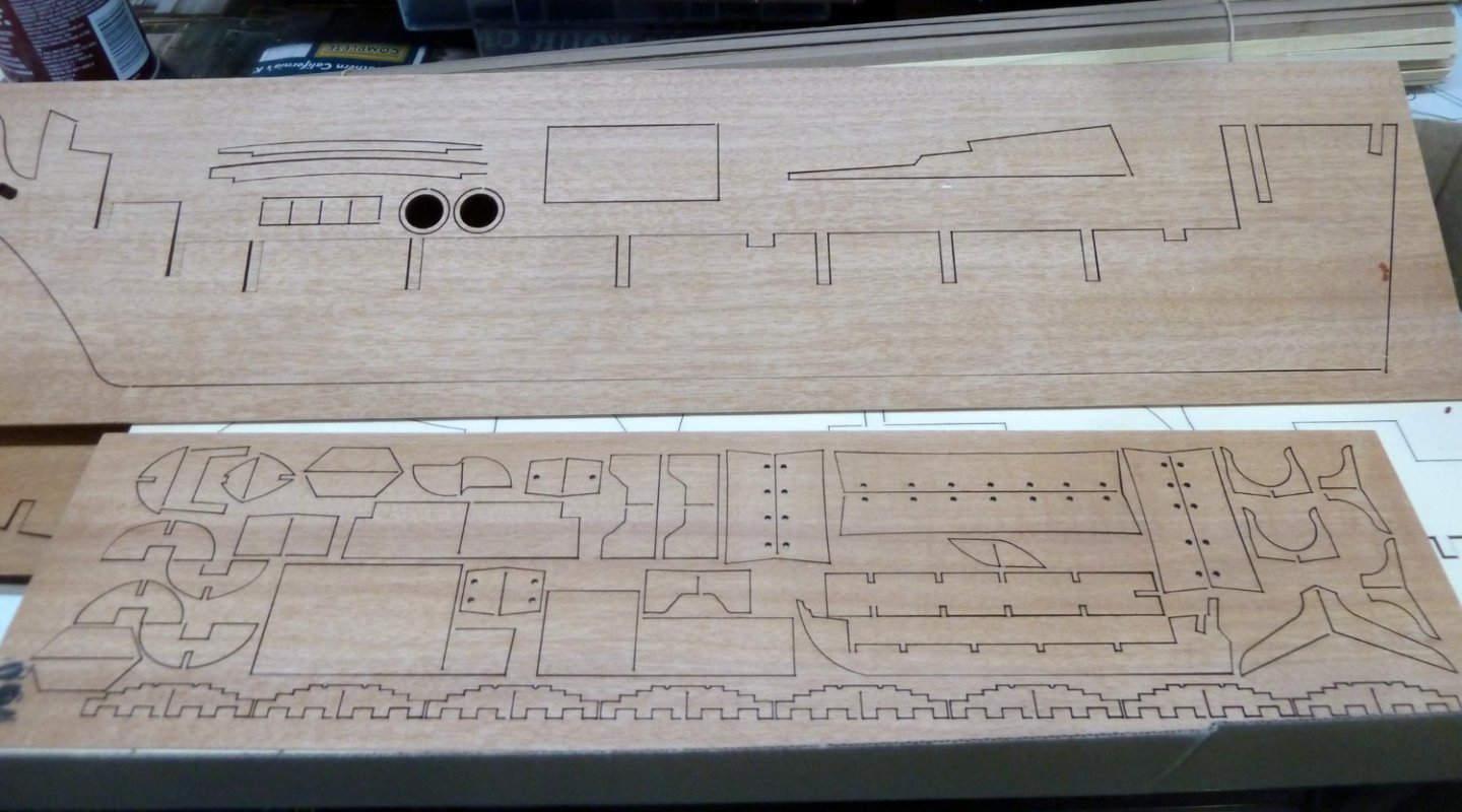
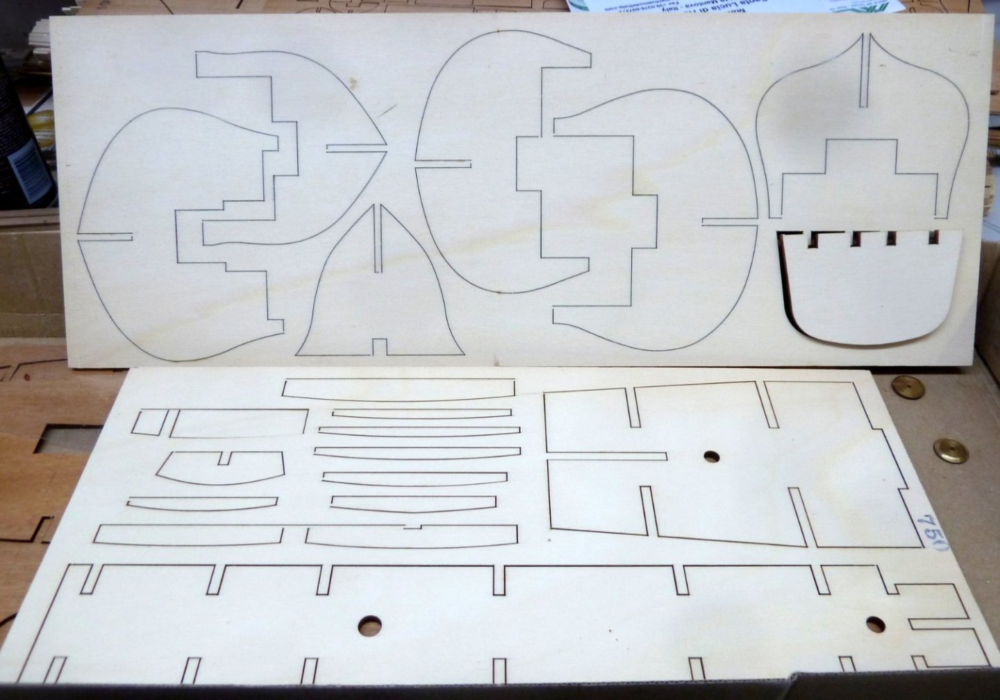
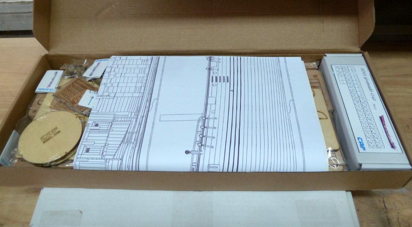
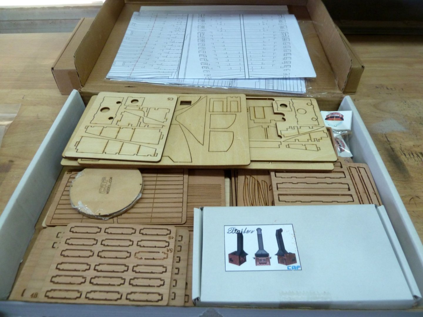
I will not be continuing work on the CAF Granado. I have parts 2 and 3 that have not been started. I built the jigs from part 2 to mark out the clamps inside the hull. There are pictures of part 1 and the jigs for the clamps in my build thread. I am asking $375 for each shipped CONUSA. If you wish to purchase both, I will accept $700 shipped CONUSA. If anyone is interested in the progress I have made so far on part 1, please let me know. Packing and shipping will be costly. I have no idea at the moment the cost of shipping, but it will definitely be in the CONUSA. I have reached the point where building a model of this type is just too much work for me and so I would like to see, at least, parts 2 and 3 get into hands of those that are building the Granado and will be acquiring these in the future. Thanks for looking.
-
HMS Granado by ir3 - CAF - 1:48 - POF
ir3 replied to ir3's topic in - Kit build logs for subjects built from 1501 - 1750
Thanks for the comments and the likes. I have not gotten to that point of installing the clamps yet. I am waiting for replacement parts to finish the stern, so I decided to fit the templates and understand how to mark out the position of the clamps. I suppose adding the clamps at this point would not be a problem but I will wait till the stern is complete. Another comment on notching out the templates. There is a CAF Granado thread on the other site and in that thread the modeler came up with the same solution and decided to notch out the templates to fit since the gunport framing is added at the end of Part 1. For those builders who wish to avoid this problem, I would suggest marking out the position of the clamps before adding the gunport framing. Until next time, IR3 -
HMS Granado by ir3 - CAF - 1:48 - POF
ir3 replied to ir3's topic in - Kit build logs for subjects built from 1501 - 1750
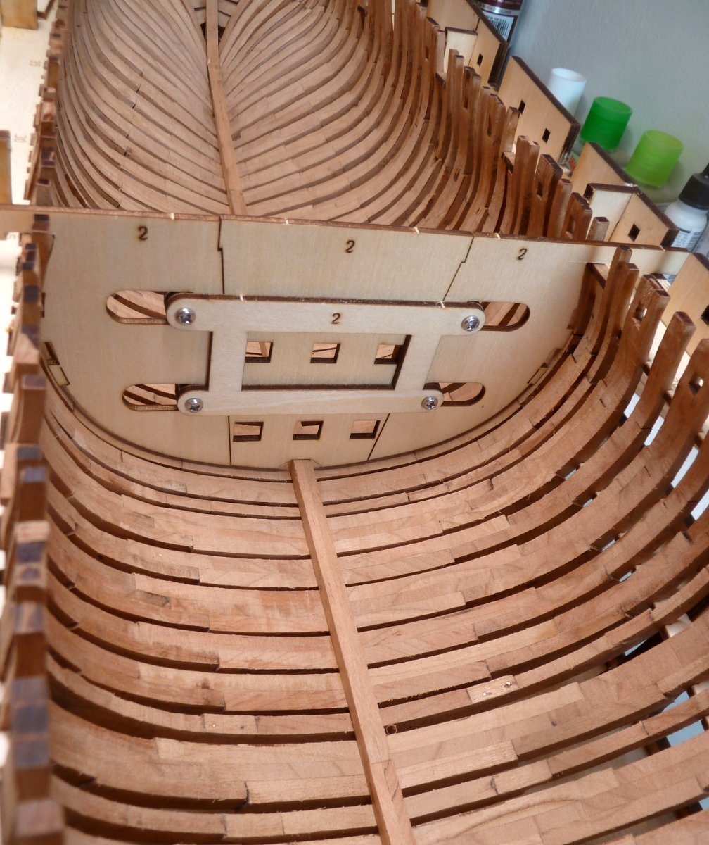
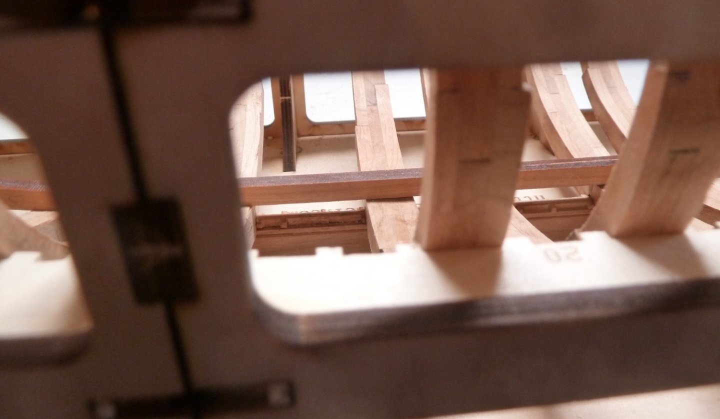
I opted for the notches and the results are very gratifying. The template sits on the keelson, it conforms to the shape of the frame, and sits properly on the assembly jig. With the template fitting properly, the deck clamps will be properly located. Now to the other three templates. The kit has the deck clamps already cut and notched. They need to be steamed to bend to the correct shape. So now it will be a short wait for the replacement stern frames and part 1 can be wrapped up. It has been a struggle up to now, but I think it will be smooth sailing, pardon the pun, from here on out. Until next time, IR3
-
HMS Granado by ir3 - CAF - 1:48 - POF
ir3 replied to ir3's topic in - Kit build logs for subjects built from 1501 - 1750
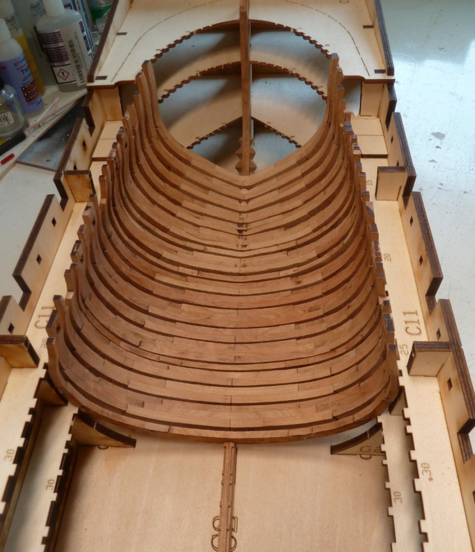
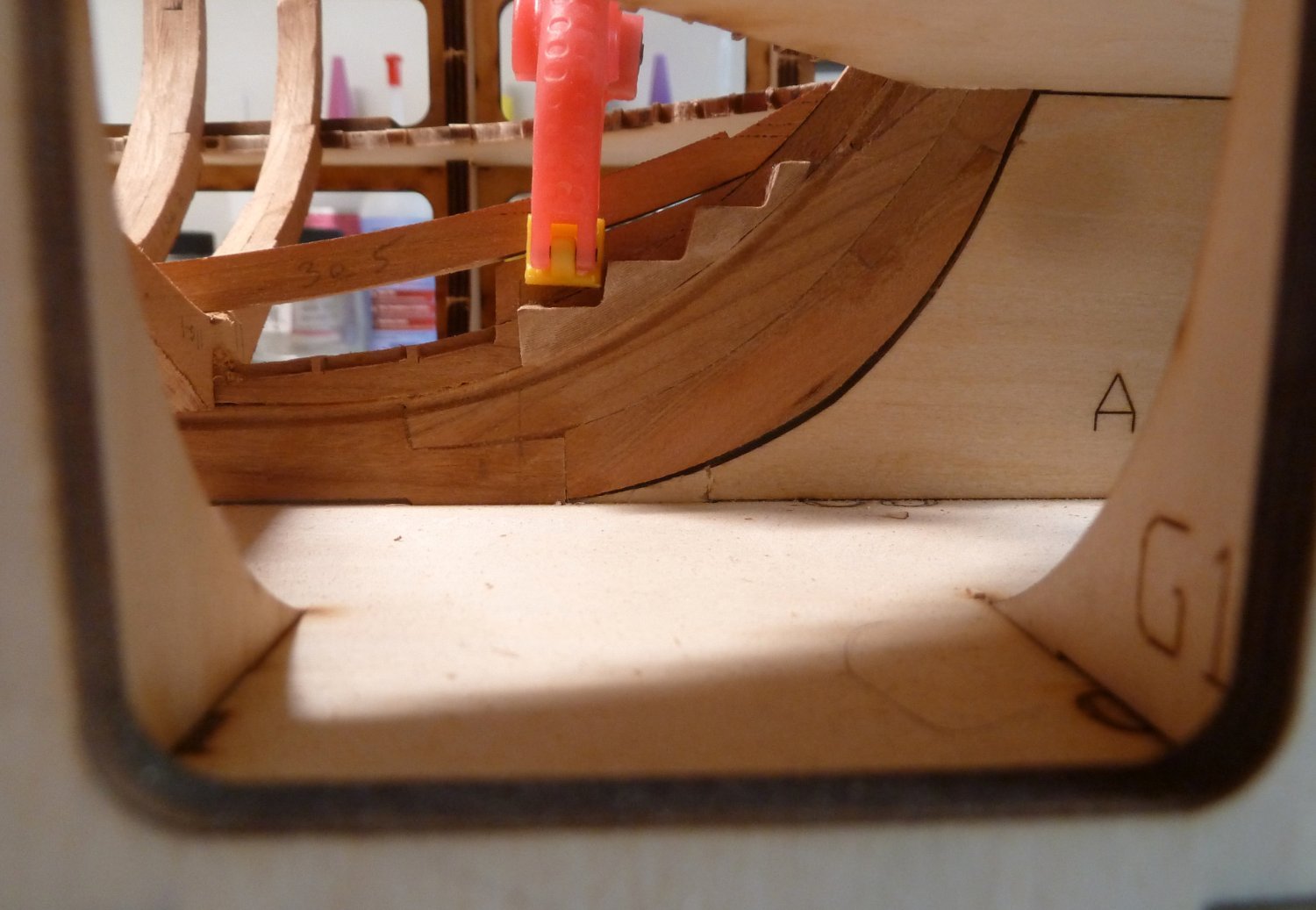
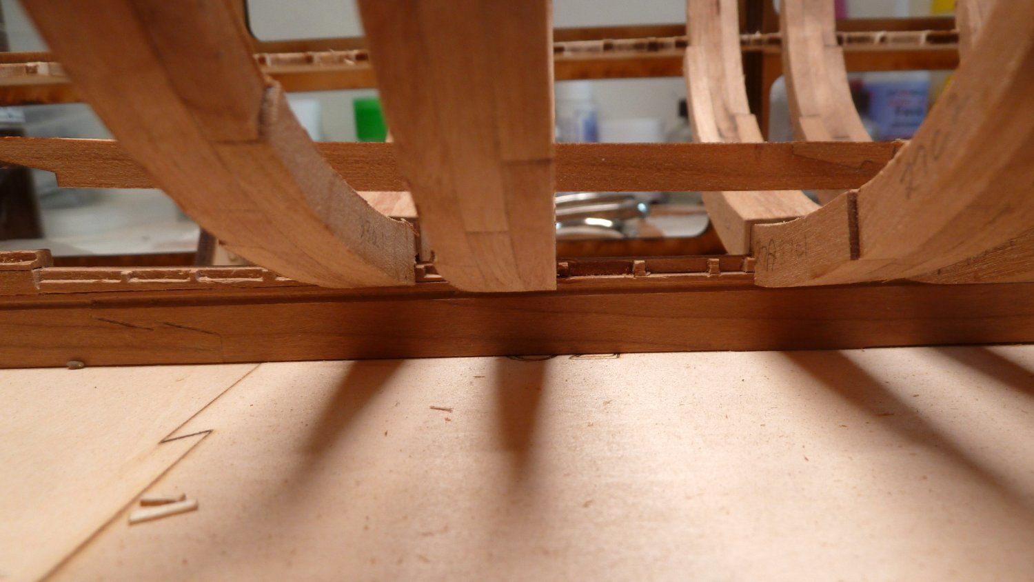
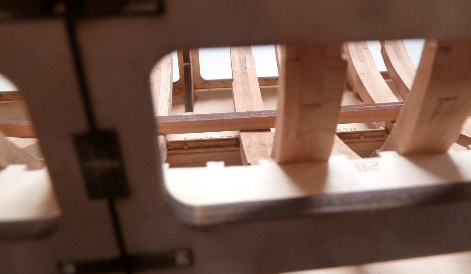
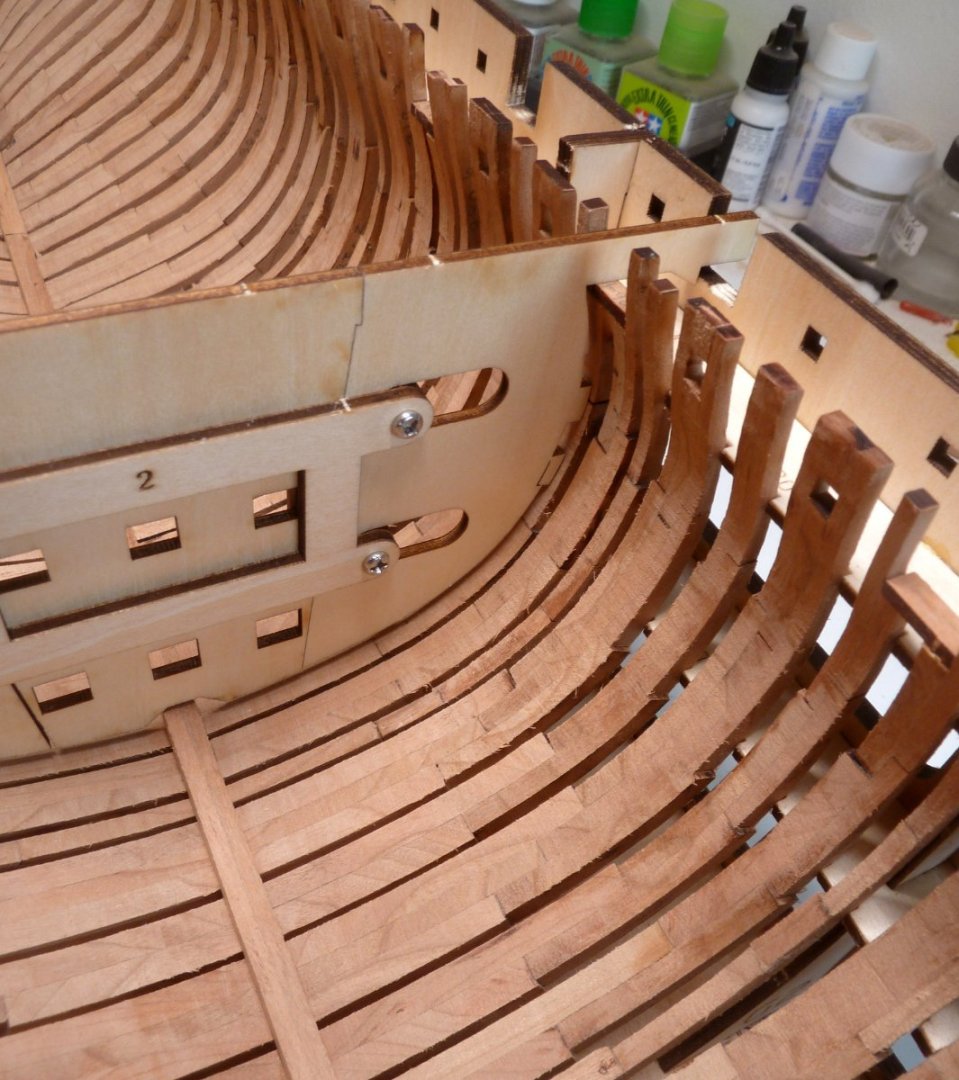
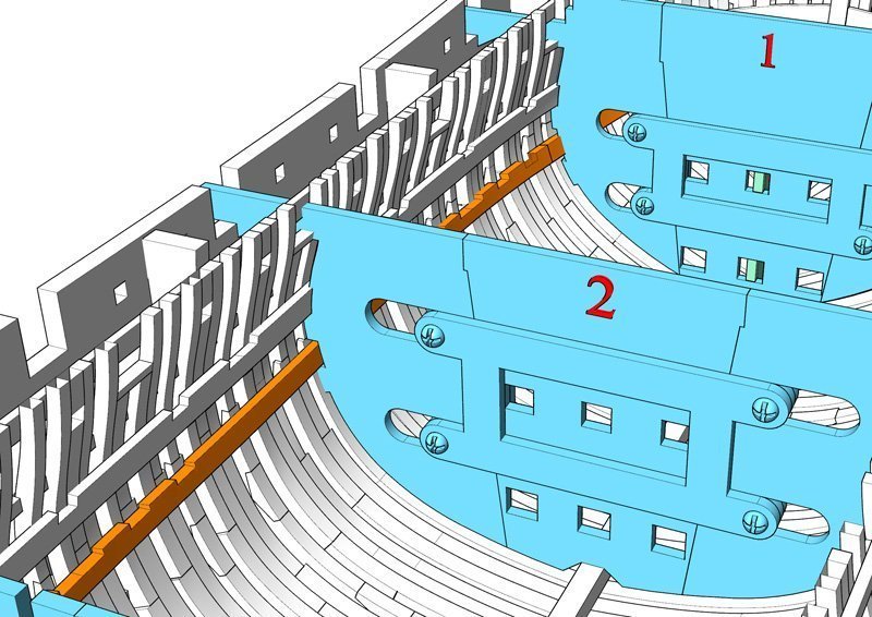
I have all the frames installed and 4 of the stern frames installed. There are two more stern frames to be installed but there was a problem with one of the CNC parts which Tom will be sending replacements. In the meantime, I started looking through Part 2 and came up with a problem. There are two deck clamps that need to be located. The kit provides very clever templates to locate the position of the clamps. The problem is that the templates appeared to be used without the lower gunport sills installed. The instructions show the lower and upper gunport sills installed at the end of part 1 and the templates shown being supported on the sills in part 2. This places the markings for the deck clamps 2mm higher than they should be. There are two choices: mark out the position of the clamps and then lower the markings by 2mm or cut 2mm notches in the templates. I am including a photo of the template sitting on the lower port sill and a picture of the design from the CAF thread showing what appears to be notches in the templates sitting on the port sills. I am tempted to do this as it will make the marking out correct. If I have to move the marks made with the templates sitting on the port sills, it will be prone to error. Any comments would be appreciated. Until next time, IR3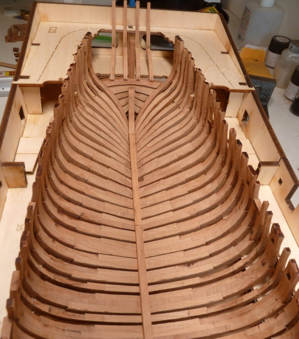
-
HMS Granado by ir3 - CAF - 1:48 - POF
ir3 replied to ir3's topic in - Kit build logs for subjects built from 1501 - 1750
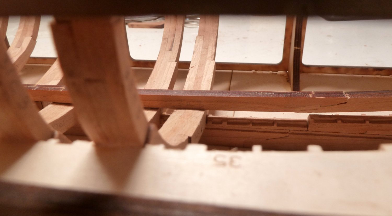
Thanks for the comments and likes, much appreciated. The before and after pictures of the keelson are included. Now that the keelson sits properly on the frames present and the ends of the keel structure, each added frame can get adjusted before gluing in. Should make adding the remaining frames a simple task. More to follow. The first two pictures show how far off the keelson was with respect to the installed frames and the second two show the correct fit.


-
HMS Granado by ir3 - CAF - 1:48 - POF
ir3 replied to ir3's topic in - Kit build logs for subjects built from 1501 - 1750
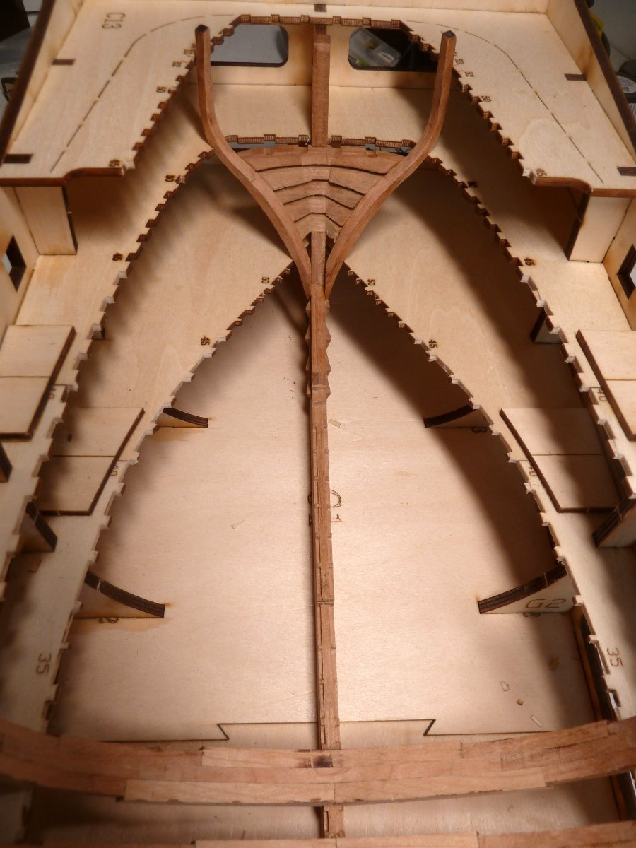
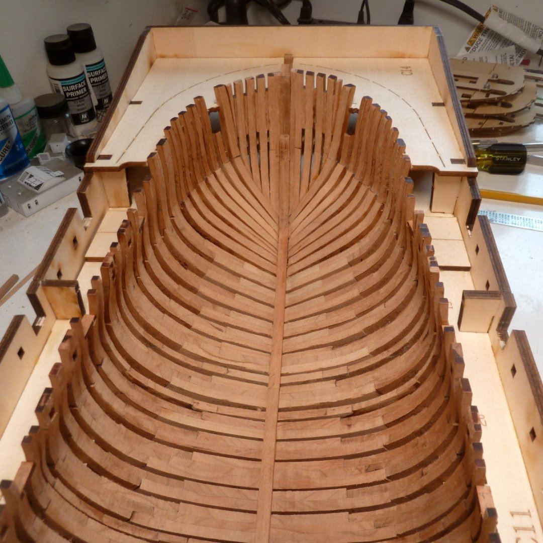
Frame 53 is in. With nothing more to do with the keel I started adding frames. This is where it starts to get enjoyable! Not having any previous experience my thought is to place the frames that have the height setting features that are built into the assembly jig. Having done this, the selected frames have the correct height. Next, fit the keelson. With this properly fitted, but not glued in yet, the frames that are installed will be correct and will be the reference for installing the remaining frames on the keel. I hope this makes sense. More to follow.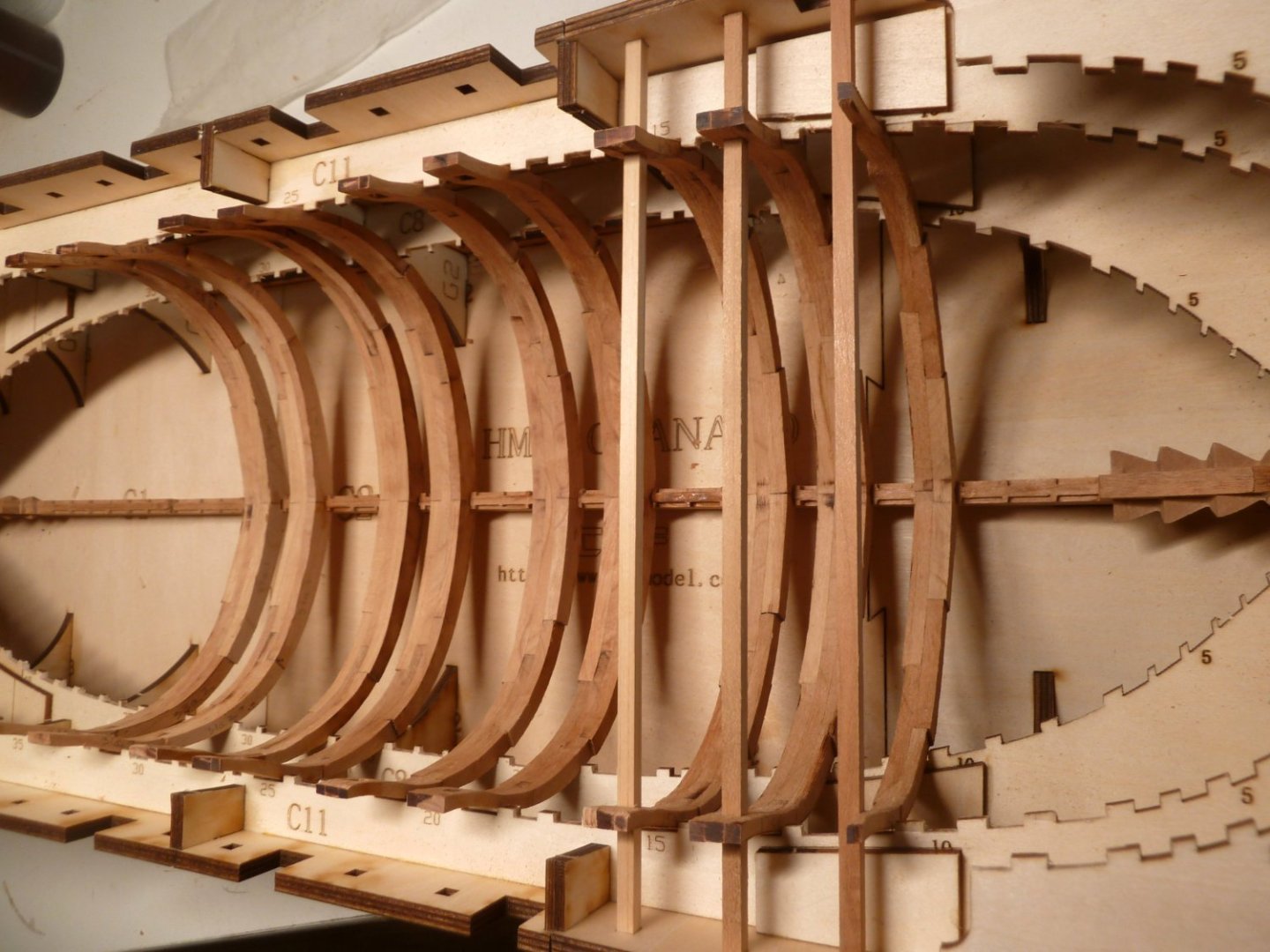

-
HMS Granado by ir3 - CAF - 1:48 - POF
ir3 replied to ir3's topic in - Kit build logs for subjects built from 1501 - 1750
All of the frames that sit directly on the keel, 8 - 45, are finished and the built-up bow frames are roughed in. It was nice that the frames 1 - 7 fit very nicely in the building jig and required very little adjusting of the slots in the jig for a good fit. Now to get the aft frames 46 - 53 installed. I didn't get a picture of frames 27 - 45 installed so next update will have all the frames shown.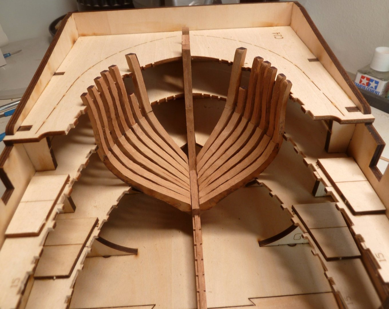
-
HMS Granado by ir3 - CAF - 1:48 - POF
ir3 replied to ir3's topic in - Kit build logs for subjects built from 1501 - 1750
More progress. Frames 8 - 26 are now roughed in. Now starting on 27 - 45. What bothers me a bit is that even building directly over the plan, some of frames seem to be to narrow. This to be dealt with when the frames are finalized and then glued to the keel. More to come.