
HOLIDAY DONATION DRIVE - SUPPORT MSW - DO YOUR PART TO KEEP THIS GREAT FORUM GOING! (Only 13 donations so far - C'mon guys!)
×


ir3
-
Posts
336 -
Joined
-
Last visited
Content Type
Profiles
Forums
Gallery
Events
Everything posted by ir3
-
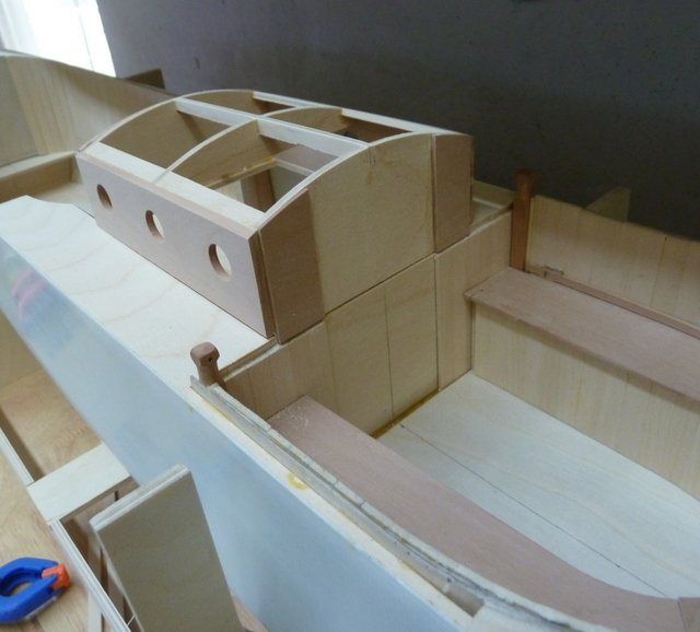
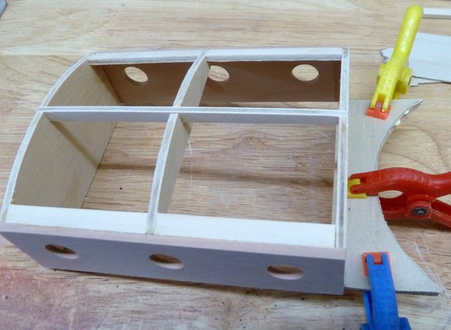
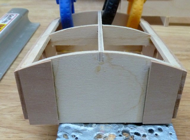
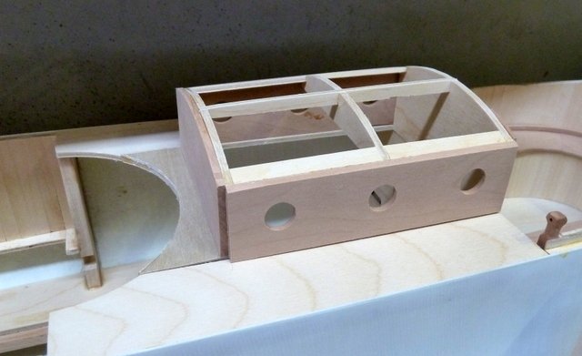
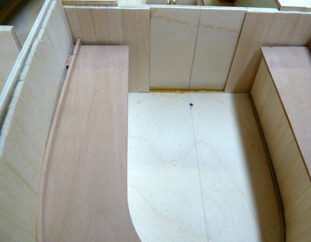
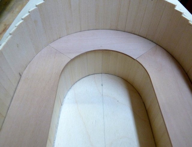
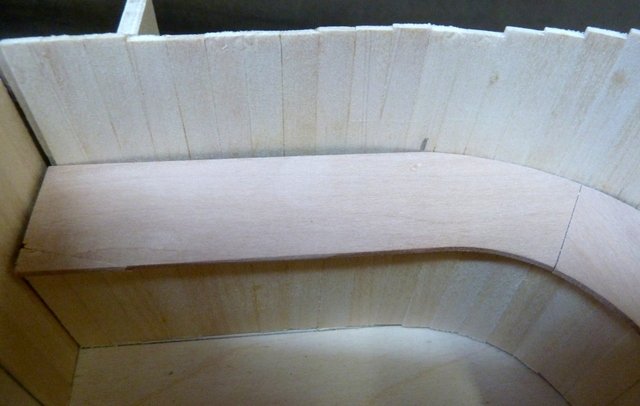
I wasn't happy with the way the bench and paneled backing were fitting. There was a gap between the backing and the turtle deck that needed fixing. The result was now the bench was too short so I lengthened that and now it is snug up against the rear bulkhead. Still need some fine tuning but I am just about there. The cabin has been started. It is all finished in Pear and should take a nice finish. Just the basic structure of the cabin is completed. There is a lot to do but it is a start. The heat is back so next update will probably be tomorrow afternoon. Until next time, IR3

-
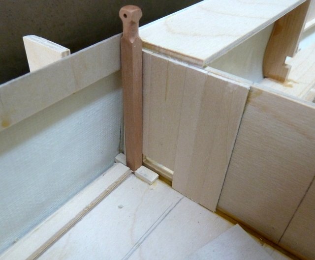
Actually one more item for the aft cockpit. The mooring bitts need to be fitted. They are removable along with the other pieces in the aft cockpit. There is a base to set the bit in, the paneled backing is cut back to fit and the bitt sits nicely. It has a final piece that goes on the caps once they are installed. One down and now to the other side. Till next time, IR3
-
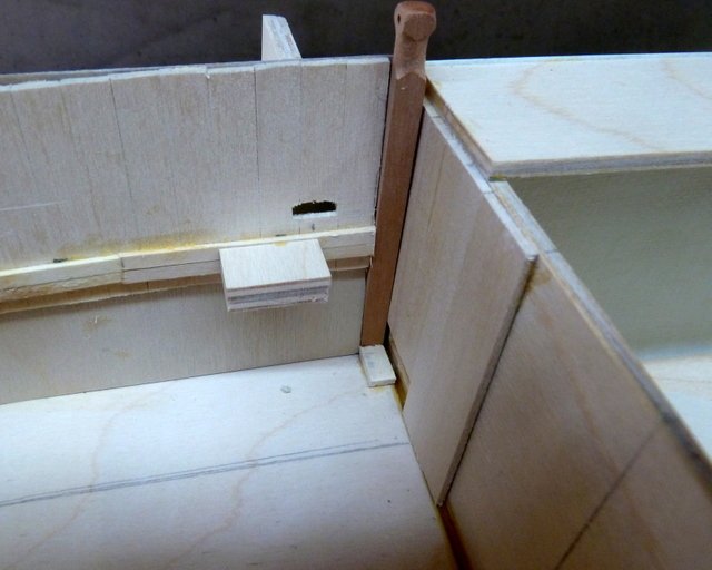
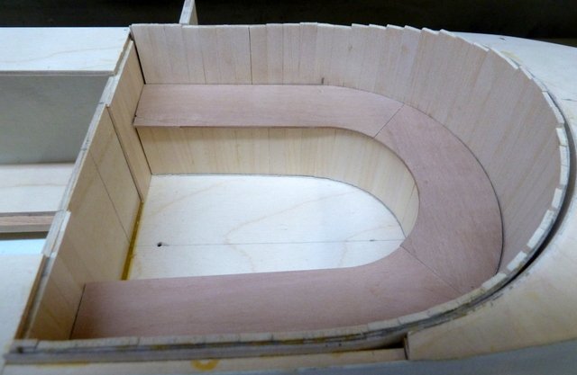
We're gaining on it! The panel backing is now correctly located and the seat fits nicely. The trim strip between the seat and the paneled backing acts as a clamp to hold the seat in place. There are three slots in the panel backing at the seat level and the 1.5 x 4 mm Pear strip has 3 tabs glued on. These tabs fit into the three slots holding the seat down. The tabs are placed so there is a bit of compression in the trim strip and keeps it against the paneled backing. Very clever! There is still one slot to be made and a bit of fine tuning. The paneled backing needs to be faired to the Turtle deck and the cutouts for rudder servo and wiring need to be done. I am looking for Light Oak stain for the cockpit and other parts of the interior. I have searched the net and I come up with blanks. It appears Light Oak is not a common color. Blackfriars has the stain that is recommended, Light Oak Gloss Varnish. The closest is Classic Oak which I don't mind. I realize that it is a builders choice as to what stains to use but my experience is zero in this area. I will continue looking but any suggestions would be appreciated. Until next time, IR3
-
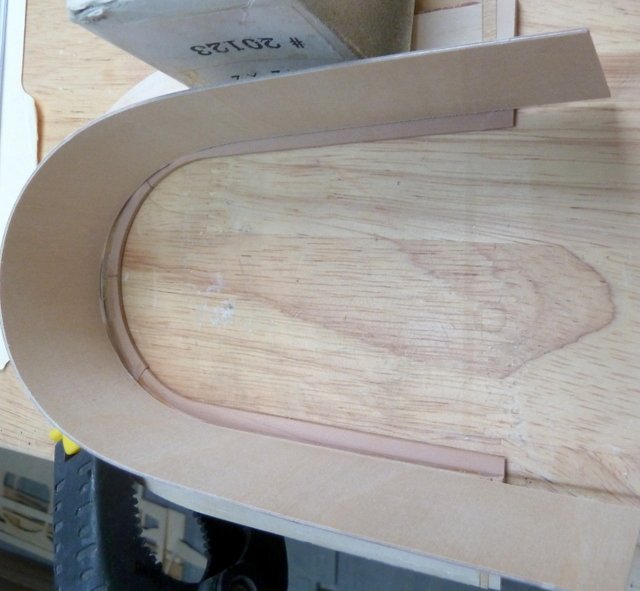
Thanks Bob, It is a challenge but no fault to the instructions, just the cobwebs in my head. I think I am over the problems and can now finish up the rear cockpit. I now have the locating strips for the cockpit paneling in place. With the paneling in place and the seat in, the gaps between the seat and the paneling are almost non-existent. The gap between the paneling and the Turtle Deck will be covered by the capping around the cockpit. Now I can finally get to the servo installation and the clamp to hold the seat in place. Until next time, IR3

-
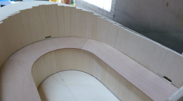
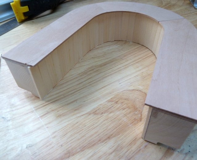
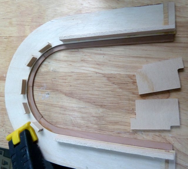
The aft cockpit seat is just about finished. The lower skirt paneling is in, a repair was made to the seat to fix my ineptitude with the table saw. The bottom of the skirt needs sanding and I need to think about the 0.8mm Pear rear cockpit floor. I went over the instructions and pictures several more times and it all comes clear now. Both the rear cockpit seat and paneling are removable. Makes a lot of sense since maintenance of the rudder and rudder servo might be required. The gaps between the seat and the cockpit paneling are covered up by the 1.5 x 4 Pear strip the clamps the seat to the cockpit paneling. The gaps in the cockpit backing with the turtle deck and the hull sides are covered up with capping strips. I need to do a little more shaping of the cockpit paneling to reduce the gaps a bit. A lot of time spent but disaster averted. If I glued in the cockpit paneling it would have been a disaster. Next up, reinstalling the seat support strips on the cockpit paneling, making cutouts and mounting the rudder servo and the seat hold down assembly. Till next time, IR3
-
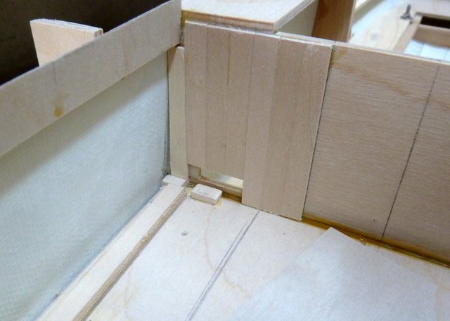
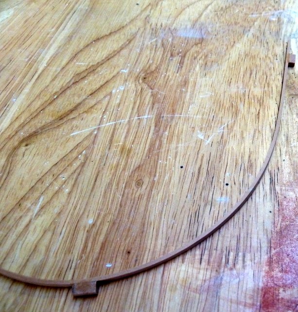
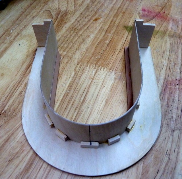
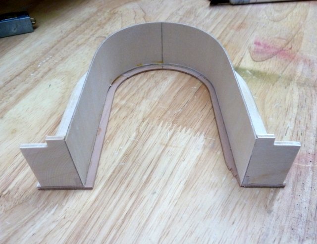
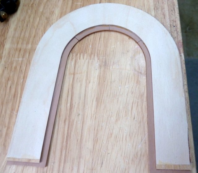
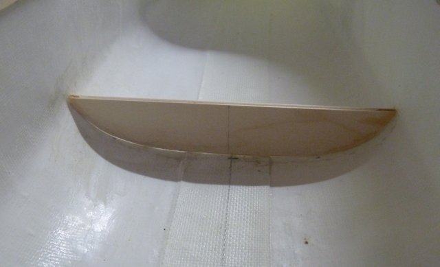
There are still a few measurements that I do not fully understand as of yet so I did email Brian Marten, the designer. In the meantime, I started on the removable bench. I think once the bench is finished, the permanent position of the main cockpit paneling can be determined. The seat is a laminate of the plywood seat base and the 3 piece pear seat. There is a skirt at the foot of the seat which is located by using some strips glued to the plywood seat base with the correct clearance for gluing in the skirt. The skirt is shown dry fitted and is quite long. This will be adjusted once the final length of the bench is determined. More to follow, IR3 THE END PLATES WILL GO ON AS SOON AS THE PHYSIICAL LENGTH OF THE SEAT ASSEMBLY IS DETERMINED.

-
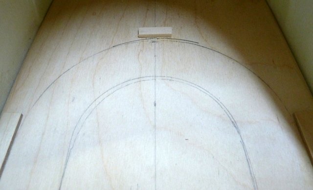
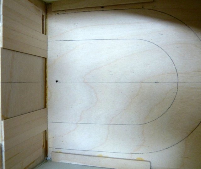
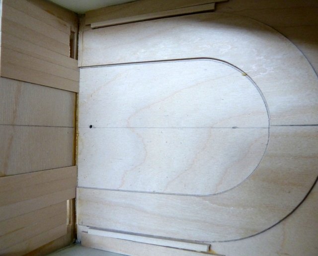
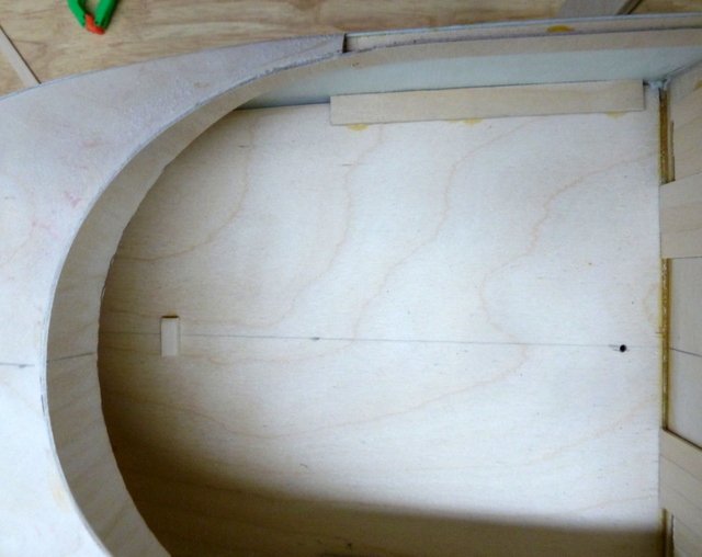
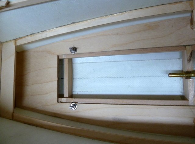
I didn't need to contact Brian Marten after all. After several reads of the instructions and looking at the pictures it turns out that the two spacers on the rear cockpit floor are in the wrong place. The short one aft is OK. What needed to be done is to use the plywood cockpit seat as a template and draw it on the rear cockpit floor. The spacers need to be parallel to the sides of the seat and spaced about .8mm from the edge of the seat to account for the thickness of the aft cockpit panel backing. Now when the panel backing with the paneling is in place and the seat supports are in place, the shape will conform to the outline of the seat. The rear cockpit panel backing is fixed. The seat is removable and has a unique way to lock the seat in place. More to follow, IR3
-
After doing the work in the last post I discovered a problem. I had to disassemble the plywood seat bottom from the planked cockpit backing and remove the bench support strips. I need to check the sequence of assembly with Brian Martin to either make sure I understand what needs to be done and show me where I am going wrong. It is basically my interpretation of the instructions that is the problem. More to follow, IR3
-
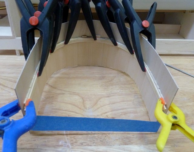
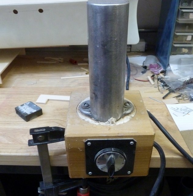
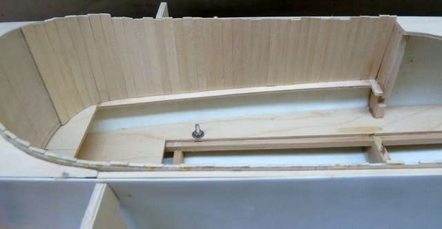
A bit more work on the aft cockpit before the heat set in. The support strips for the seat are in place. The plywood seat is in place and the pear seat tops are are just laid in place. They will be lightly sanded to get a good fit. I do almost all of my bending using a Luthiers Bending Iron. Years ago I built a Classical Guitar and the bending iron was an absolute necessity. If you are doing a lot of wood bending for your ship models I strongly suggest looking into acquiring one. It saves a lot of time soaking and waiting for the wood to saturate. When the heat is high enough, after wetting the wood the bending iron turns it to steam and shaping the wood becomes quit easy. However, at these high heats care must be taken so the wood isn't scorched. I have not read past the instructions following the installation of the seat supports but there is a lot to do. Until next time, IR3


-
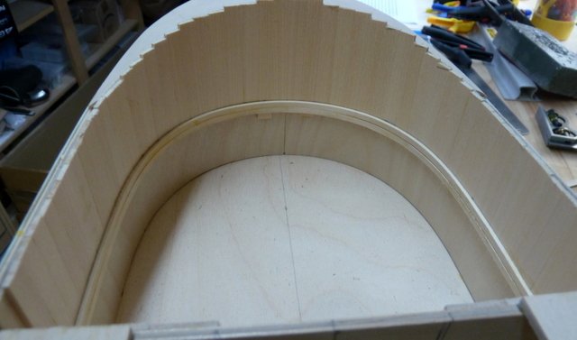
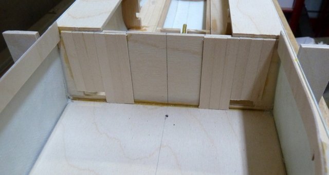
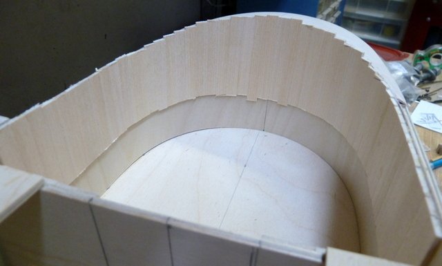
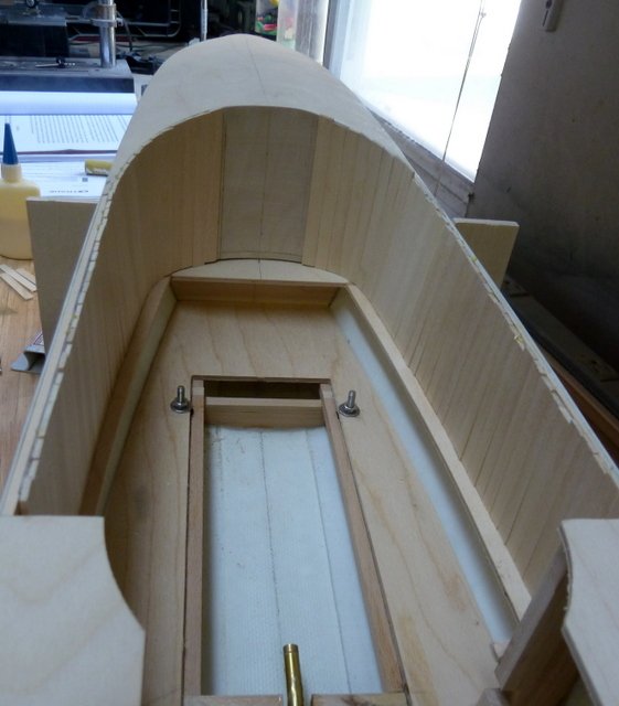
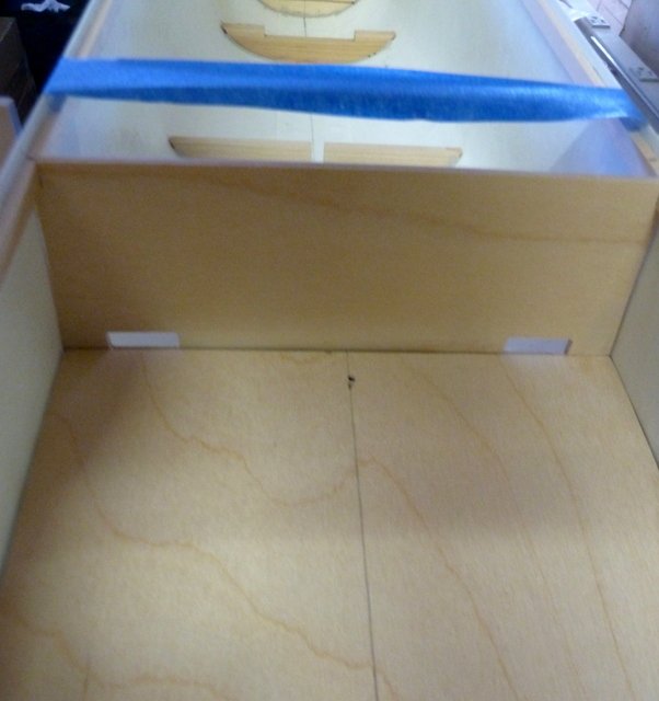
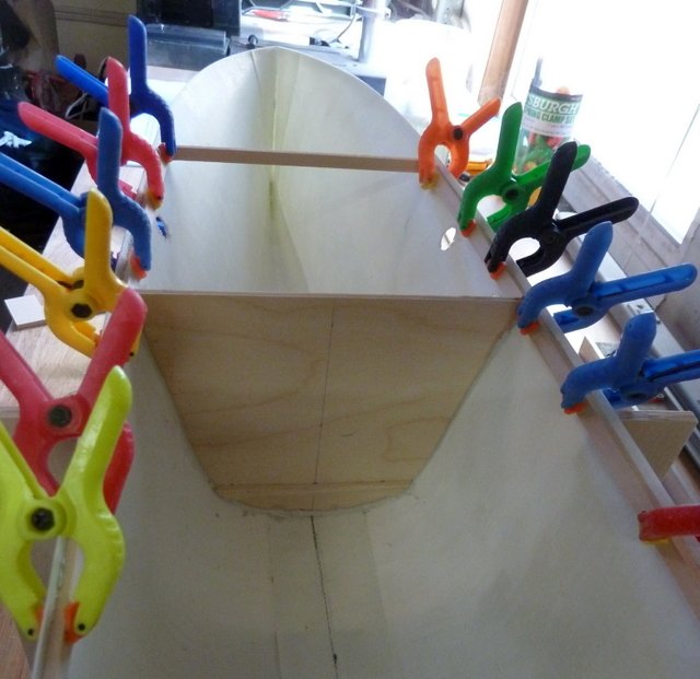
Well, yesterday was very interesting and not very productive. First a notice from the credit card company indicating my card has been compromised. While going through all of the suspicious charges we had an area wide power failure. Not one of the roving types. The temperature was back up to 109 and with no AC in the shop, not much progress. Power came back on around 2:30 in the afternoon but couldn't get any work done until late last night. Not without problems this morning, the cable network was out until 9:00 AM. Hopefully today will be less eventful. Starting on the rear cabin, there is a fixed veneer piece forming the general shape of the aft cabin walls. This piece is permanent but the aft cockpit is removable to gain access to the rudder servo, rudder tiller and other radio parts which will be hidden under the aft cockpit seat. Spacers were glued into the floor to maintain verticality of the cockpit walls while assembling. The aft bulkhead has been paneled. The cockpit paneling backing sheeting was fitted and the paneling was glued in. As per the front cockpit, once the glue has cured it will be faired into the aft turtle deck. Next step will be to install the seat support. There is a lot more detail in building the aft cockpit so more to follow. Until next time, IR3
-
Hi Grant and thanks for following. The front cockpit paneling is faired and work has started on the aft cockpit. Unfortunately, the heat has driven me out of the shop so no progress until tomorrow morning. 110 degrees today and 105 for the next two days. Work will have to be done late evenings and early mornings for the next few days. Till next time, IR3
-
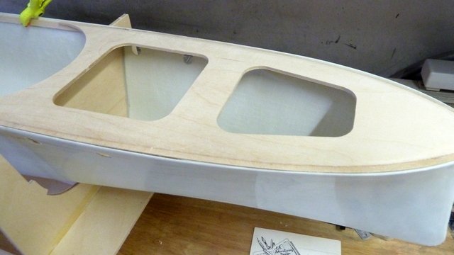
Thanks for the link to Exclusive Models. I made contact and am considering the Henry. A wonderful addition to the MHB collection. The main cockpit backing sheeting for the paneling is installed and the paneling in place. It needs fairing to the turtle deck and to the hull sides. This will be done when the glue is thoroughly cured. The center area that is not paneled is for the forward hatch door. The next effort will be the rear cockpit. It has a very detailed assembly process. Until next time, IR3

-
Their kits are extremely rare and when one does show up it is snapped up pretty quickly. It is a testament to the very high standards the kits and steam plants are manufactured. I was very fortunate to acquire the ones that I do have. They will be subjects for future build threads. I believe Project X is still available. It's back to the shop early this morning before the excessive heat drives me out, Until next time, IR3
-
Thanks Bob, it is a pleasure to work on a model with the steam plant designed into it. I am really enjoying this build. I tried stuffing a steam plant in a Model Slipways Envoy and I must say, if a model is not designed for a steam plant it is extremely difficult to install one. The Marten, Howes & Bayliss kits were designed specifically for steam power which makes them very desirable for model steam boat enthusiasts. Until next time, IR3
-
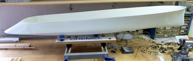
A bit more work on Project X. The forward floor supports are installed, the deck pieces are glued in, and the aft turtle deck is installed. The weather is a bit kinder today with highs expected to be around 97F. The shop AC can handle this but the next 4 or 5 days the furnace will be turned back up to high. The next step is shaping the front cockpit paneling. Until next time, IR3
-
The fluorescents arrived today and I now have reasonable lighting. Doesn't help the myopia, however. The rear deck is getting glued in. The rear turtle deck will be built over this. The formers to support the main deck are being epoxied in place and the deck pieces are dry fitted for now. They will be glued in once the epoxied support formers cures. Can't do much more in the shop today. The weather forecast today is for ~110 degrees F and the shop AC can get that down about 20 degrees, much too hot to work. Probably late this evening to glue on the main deck pieces and assemble the rear turtle deck. Until next time, IR3 OOOPS, FORGOT. THE THREE PART KEEL IS IN PLACE. NEEDS FINISHING AND WILL COME LATER.

-
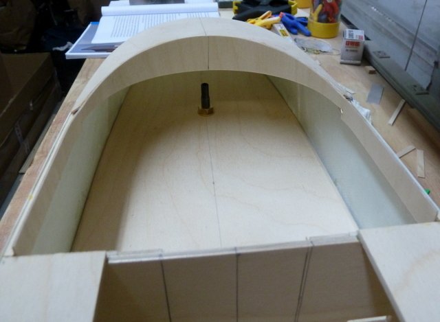
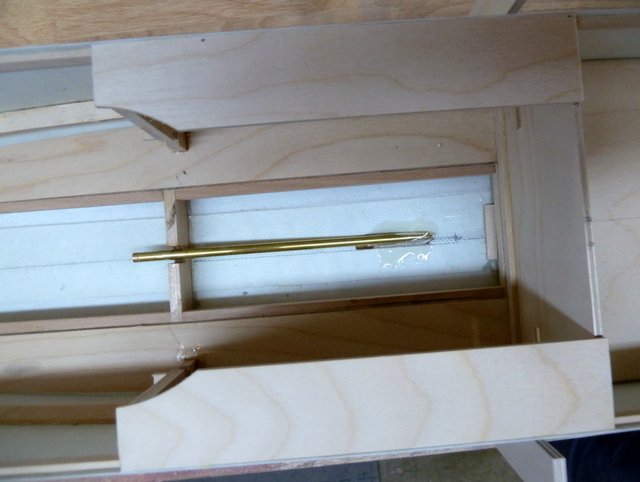
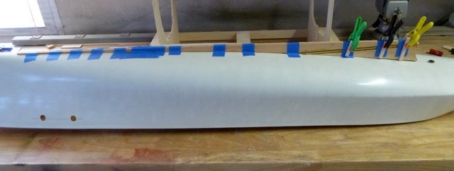
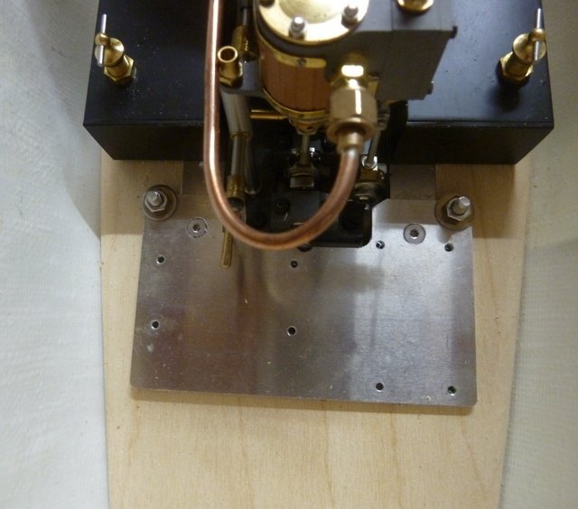
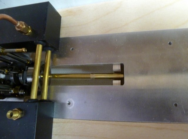
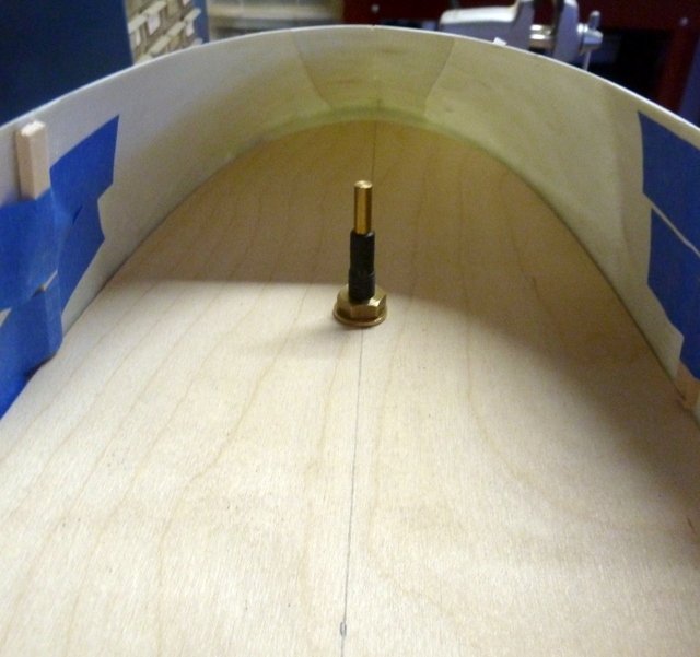
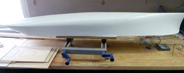
The front cockpit floor is centered and installed The steam plant was installed to test fit. The aft end of steam plant base fits under the 3mm x 7mm strip across the bottom of the rear bulkhead. The forward end of the steam plant base is bolted in. The installation of the prop shaft and prop shaft tube is facilitated by the use of a temporary brass spacer cut to a specific length supplied with the steam plant. With the prop shaft tube and prop shaft in place using the spacer the exact position of the prop shaft tube is set. After centering the prop shaft tube it is epoxied in place at the floor support and at the point where it exits the hull. This ensures the correct placement and alignment of the prop shaft tube. The boiler was removed to do this part of the prop shaft installation. It is a pleasure to install a steam plant into a model which is specifically designed for the application. Next step is to install the keel parts. Until next time, IR3
-
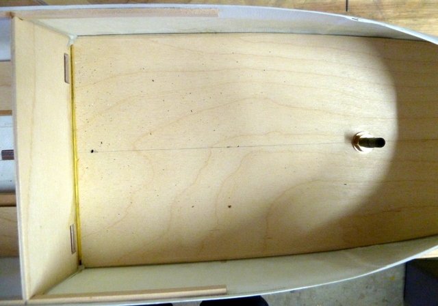
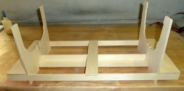
A bit more progress on installing the floors. Sorry about the absence of a picture but the aft floor rests on a floor support bulkhead, the rudder bushing and a support strip on the aft side of the aft bulkhead. All pieces were adjusted to make sure the aft floor is level. The 7 x 13mm engine bearers are in. The forward floor has been drilled and M4 bolts installed. They fix the forward end of the engine mounting plate. The aft end of the mounting plate will fit under a 3 x 7mm strip glued to the front side of the aft bulkhead after the floor is installed. There is still a bit of fitting needed for the central floor. Next step will be to align the prop shaft and start on the keel. Sorry about the shadows but my fluorescent lighting in the shop has failed and finding replacement bulbs in a chore. The fixture is 40 years old, the GE bulbs are no longer produced and the Sylvania bulb end pins may not seat properly. Until next time, IR3

-
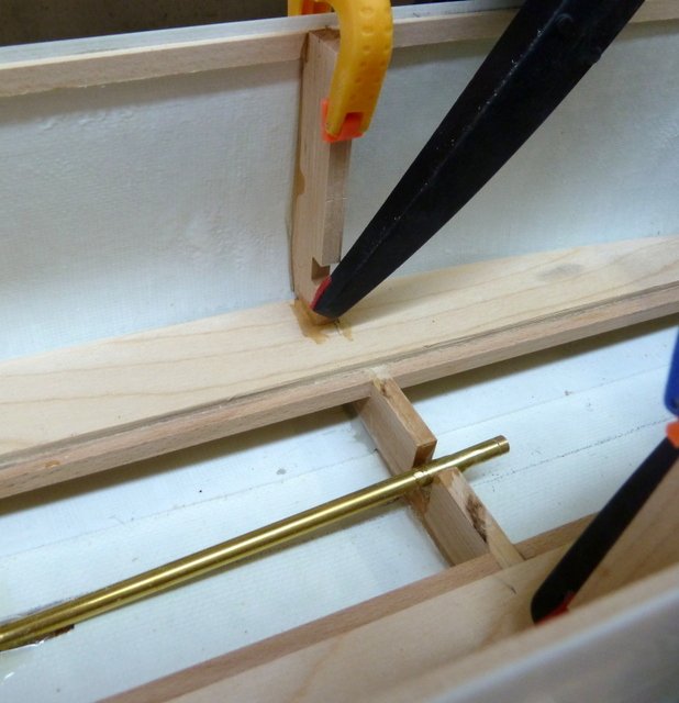
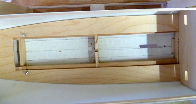
Thanks to Gecko and rereading the instructions and following the pictures it finally dawned on me what is happening. The 7 x 13 mm strips are cut to exact length of the required distance between the forward and aft bulkheads. This defines the exact position of the aft bulkhead. There are two floor supports that go between the front and rear bulkheads. The 7 x 13 mm strips are temporarily laid onto the floor supports and on the 3 x 7mm strip on the forward bulkhead. Where the ends of the strips land on the rear bulkhead defines where the floor support goes on the aft bulkhead. This took a while for my aging brain to work out. Once that is accomplished and the aft bulkhead is temporary installed, attention now is paid to the aft floor. The floor support is set into the hull at the appropriate point show on the plans. The aft floor is sanded and shaped to fit and is inserted into the hull. The problem is to find the floor support strip that goes on the aft bulkhead. Using a level, the aft deck is adjusted until the level shows 0 degrees. This is marked out on the aft bulkhead and the deck support strip is glued on allowing for the thickness of the floor. Finally, the bearing for the rudder shaft is installed in the hull. The hole in the aft floor is oversize to make sure the rudder post can be adjusted to vertical in two axes. I will be fabricating a small disk drilled to the exact diameter of the rudder shaft housing and this will be glued in place once the correct rudder orientation is set. A bit mind boggling for me but it is all working out. The heat has driven me out of the shop. Even with the A/C it can't overcome the summer heat here. The next update will finalize the rudder installation and the cutting and installing of the 7 x 13mm strips which support the steam plant. Also permanently fixing the aft floor and aft bulkhead. Until next time (if my psychiatrist allows), IR3

-
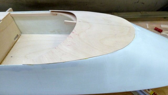
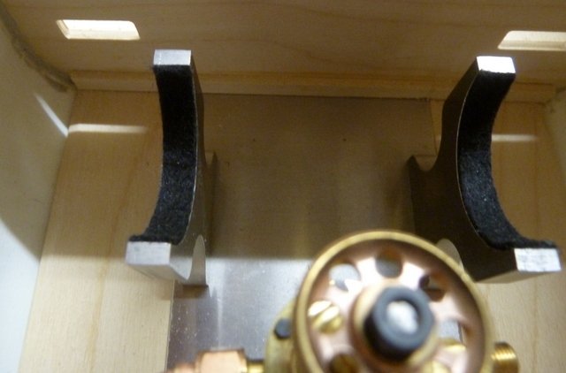
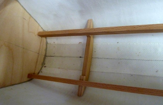
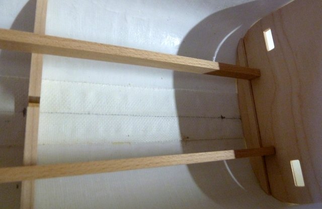
GECKO, Thanks for the links. You did a wonderful job on this kit. I will follow your advice and make some more brackets to preserve the beam of the boat. I am at the point of installing the central floor and there is a major discrepancy between the plans and the assembly pictures that came with the instructions. I contacted Brian about this but I will also ask you since you seem to have got it right. The plans do not show the 7 x 13 mm beams flush with the 3 x 7 floor support on the forward bulkhead. The pictures show the 7 x 13mm beams sitting on the 3 x 7mm floor support. The pictures also confirm that. Did you also notice this problem and how did you come to the conclusion. In the mean time, I have the forward turtle deck installed but it does need finishing. The .5mm fiberglass over the turtle deck is an excellent idea. Until next time, IR3 OOOPS, MY ERROR. THE 7 x 13 mm BEAMS ARE FOR POSITIONING THE DECK SUPPORT ON THE REAR BULKHEAD. THEY ARE NOT STRUCTURAL. MORE TO FOLLOW IN THE NEXT POST!!!!!
-
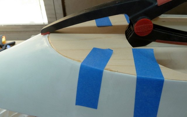
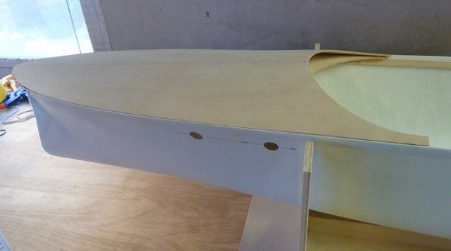
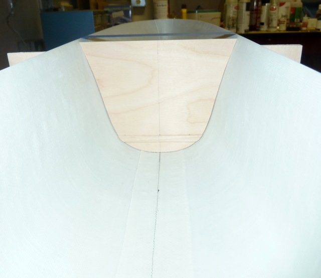
A bit more progress The forward bulkhead is now cemented in. I am using Liquid Nails and it takes about 24 hours to ensure the bond is solid. It will still cure after that for a while. The deck supports have been installed using Liquid Nails. The forward false deck is ready to install after a slight bit more trimming. It has a chamfer around the edges so that after being glued in there will be a 1.5mm reveal of the hull. There are some formers that will go on the false deck shape the 1.5mm veneer sheeting which will constitute the actual forward decking. Holes for two portholes each side have also been drilled. Next task is to glue in the false deck and get the formers on that shape the veneer. Till next time, IR3
-
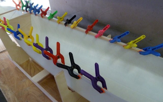
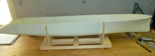
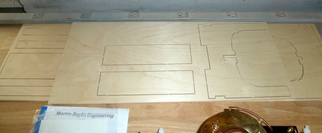
The cradle is built but will remain unfinished until the end of the project. It serves both as an assembly platform but also a display stand. When the project is finished the sides will be cut down. The top edges of the hull were sanded down to a line molded into the hull. The hull was leveled and the sides were checked to make sure they were at the same height. This will ensure the decks are true both fore/aft and side/side. A center line was drawn at the bottom of the hull and the forward bulkhead has been fitted but not glued. This bulkhead has a 3 x 7 mm strip to support the floor. Next task is to epoxy the forward bulkhead in and get in the deck shelf strips. Until next time, IR3
-
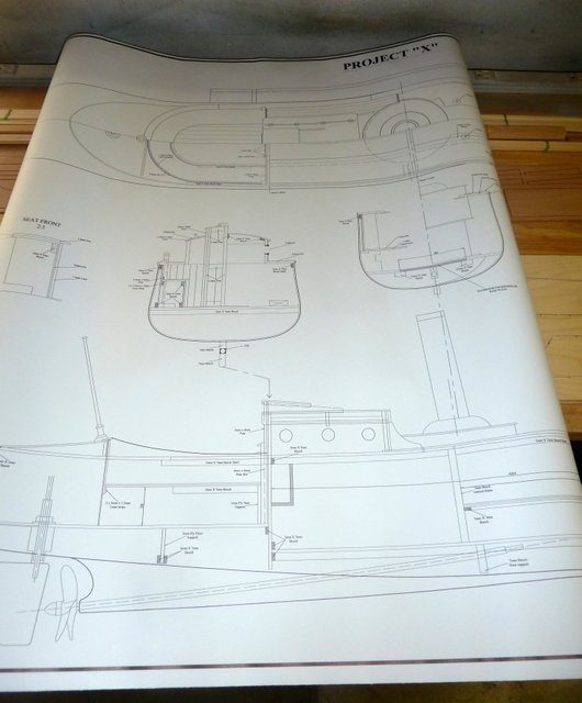
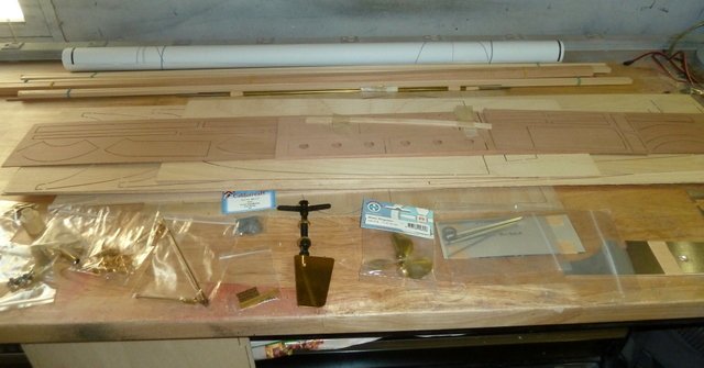
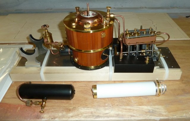
After struggling with restorations on several kits, it just turned out to take much to much time and very little progress was made. I have several Marten, Howes, Baylis kits and decided that building a kit with high quality materials and excellent instructions accompanied by photographs was the next thing to do. I chose a project the Brian Marten and Liz Howes made available in 2019. It is their Project X. It is a prototypical concept that M and H designed to represent a fast commuter launch of length 50 feet. Its in 1:12 scale with a length of 50" and a beam of 7". With the steam plant installed it has a freeboard of about 2.85" so for steaming purposes it will remain in a very calm pond or swimming pool. The Steam Plant is by Martin Baylis custom built for this project. It is a very nice Triple Expansion Steam Engine with a Kingdon boiler. First cabin if you will pardon the expression!. I will start out with a few pictures of the unboxing and checkout of the bits and pieces. The hull is magnificent. It will be a very simple process to smooth the bulwarks and finish the outer hull. The rest of the contents are machine cut sheets of various thicknesses and woods as necessary for the various structures in the model. Also and appropriate amount of strip woods of various sizes along with several wire sizes. There are very nice fittings and a prop along with assembled rudder assembly. The instruction manual is very clear and it is supplemented with pictures showing every step of the assembly process down to installation of steam plant and position of radio components. This is going to be a pleasure to build. It is the perfect area to post a build thread as there is a significant amount of wood work and finishing that needs to be done and the MSW is the place to go for the expertise. Here are some pictures and the first build update will be the display stand. Until next time, IR3
-
Delta Queen by ir3 - Saito - RADIO
ir3 replied to a topic in - Kit build logs for subjects built from 1901 - Present Day
Thanks Chris, after basically completing the hull, the rest of the restoration was just taking toooooo much time. I have some very fine MHB kits that I need to put some time into and I do plan on a thread very soon on one of their kits.- 21 replies
-
- 2
-

-
- saito
- delta queen
- (and 1 more)
-
Delta Queen by ir3 - Saito - RADIO
ir3 replied to a topic in - Kit build logs for subjects built from 1901 - Present Day
The cabin turned out to be a total disaster. It was very poorly built using adhesives that could not be undone and without the original sprues, the pieces making up the cabin could not be reduced. The restoration of this model was a long shot but there is just too much work to be done to make it right. It would actually be a lot less stressful to find another DQ and start over. That is unlikely so this project is officially retired. The steam plant is removed and the remainder will be relegated to the wreckers. Thanks for following the restoration but and end was not in sight.