HOLIDAY DONATION DRIVE - SUPPORT MSW - DO YOUR PART TO KEEP THIS GREAT FORUM GOING! (Only 13 donations so far - C'mon guys!)
×


ir3
-
Posts
336 -
Joined
-
Last visited
Content Type
Profiles
Forums
Gallery
Events
Everything posted by ir3
-
Hi Ed, Following this thread is pure joy. An education on every page. For SJSoane and others I suggest Google "Around the Horn movies 1930's" and you will get a first hand view of the crew working in extremely rough weather. "Imaging climbing out there in heavy weather..." took very special people to do that kind of work.
- 3,618 replies
-
- 3
-

-
- young america
- clipper
- (and 1 more)
-
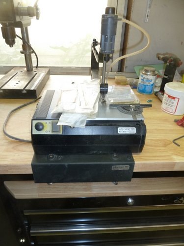
I have an early version of the MicroLux variable speed scroll saw that has had many great years of use. I upgraded to a PROXXON so this one has to go. It is in very good working condition and is very useful for some detail work requiring this type of saw. It comes with the bench mount and various blades. Note, the rip fence is under the saw blades and the adjuster just shows through, sorry about that. Asking $100 plus shipping CONUSA. Shipping estimate from 91307 to 10001 is about $31. It should be a bit less for a buyer that is closer to 91307. Thanks for looking.
- 1 reply
-
- 1
-
-
Hi Greg, excellent work. I am totally befuddled using CA on parts mostly at the scale of the Yamato. No matter what advice is given I fail miserably. Could you please relate some of your techniques as it appears to come very easy for you. Thanks, IR3
-
Just tuned in. I just love the exquisite wood work on the old speed boats. Very nice job. Keep up the good work. IR3
- 414 replies
-
- 4
-
-
- riva aquarama
- amati
- (and 2 more)
-
Delta Queen by ir3 - Saito - RADIO
ir3 replied to a topic in - Kit build logs for subjects built from 1901 - Present Day
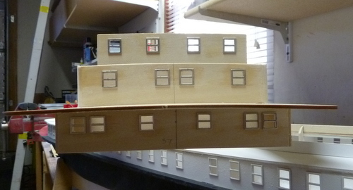
A bit more work on the DQ. The Texas (or Hurricane) deck is on and more windows in place. This brings the total up to over 150 so far. If you like windows, this is the kit for you. I had trouble at first with windows falling off after gluing. It turns out that I need to scuff up the backs of the windows to provide a good medium for the thin CA. That and kicker has the windows on pretty firmly. After priming and painting there should not be a problem with windows falling off. I still need to put in the doors. The plan indicates that they are wood panel doors which I am not going to attempt. I have the stamped out Saito doors which I might paint some wood color. I need to check some pictures to see if these are indeed painted white. BTW, one of the good parts of the kit are the stampings for the windows and doors. They actually came out quite nice. I have to deal with the shear before painting. It is really bad and due to very poor die cutting of the cabin sides. I assume that at one time the parts were die cut perfectly but as time went on not much maintenance was done on the dies. Hmm, just noticed the missing window on the Cabin deck. Until next time, IR3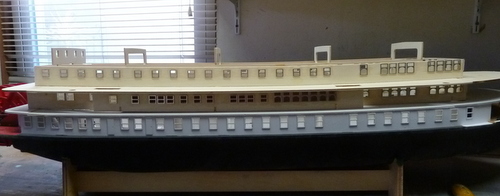
- 21 replies
-
- 6
-
-
- saito
- delta queen
- (and 1 more)
-
Delta Queen by ir3 - Saito - RADIO
ir3 replied to a topic in - Kit build logs for subjects built from 1901 - Present Day
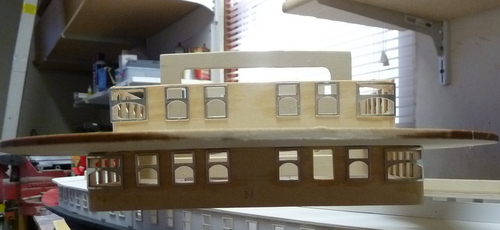
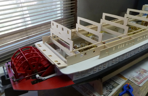
A bit more work on the Delta Queen. Many problems fitting the various deck pieces. The sheer of the boat was almost impossible to set up. With the fiber glass hull being so uneven and the frame punchings so poor the corrections could not be made until the main cabin structure was started. This was not practical. So the boat goes into the classification of Stand Off Fun scale. It is strictly a small pond or swimming pool model and will never be a show winner. I started on the main cabin structures. This is removable to get access to the interior. Not shown in the pictures is a small inner box on the first deck level to seat the cabin structure. As you can see from the pictures the sheer has its problems. I will deal with some of them but for the most part, since it is removable probably not too much effort. Until next time, IR3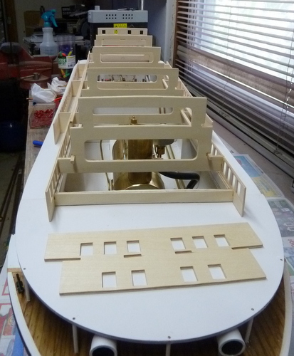
- 21 replies
-
- 2
-
-
- saito
- delta queen
- (and 1 more)
-
Delta Queen by ir3 - Saito - RADIO
ir3 replied to a topic in - Kit build logs for subjects built from 1901 - Present Day
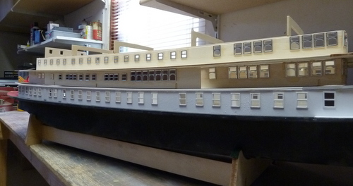
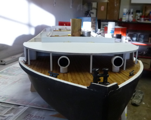
A bit more work on the Delta Queen. The door knobs have been installed but alas, unless one looks very closely the first deck obscures them. But at least they are there. The fore part of deck one is installed with the support pillars. I kind of wish I did the fore portion of the model as the Victoria. It is more presentable with staircases going up to the first deck and a different front. Of course, this is the Delta Queen and so it will be the DQ. Before going on, I need to caulk the seams between the hull and the inner structure to prevent water from coming in. There is very little free board so keeping the interior dry is an absolute must. The steam plant will be coming out for this operation. Until next tine, IR3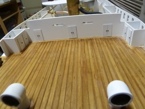
- 21 replies
-
- 5
-
-
- saito
- delta queen
- (and 1 more)
-
Delta Queen by ir3 - Saito - RADIO
ir3 replied to a topic in - Kit build logs for subjects built from 1901 - Present Day
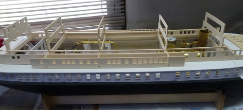
A bit more work on the Delta Queen. I aged the deck a bit using the Micro Mark product and it seems ok. It looks a bit worn and used. A few of the fittings are in place and the doors need door knobs. I need to coat the heads of some pins black and it will at least add a bit of contrast. I hate painting!!!!! Next step is to start on the next deck. Until next time, IR3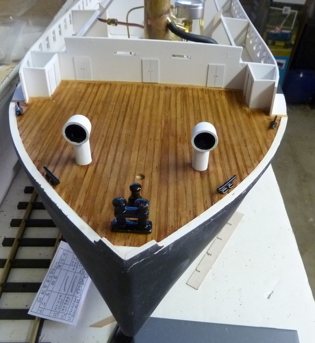
- 21 replies
-
- 5
-
-
- saito
- delta queen
- (and 1 more)
-
Hi Mike, I am not familiar with the Model Shipways Chaperon but is seems that it is large enough for a small steam engine. It would be interesting to see one of these running under steam power. Just a thought. IR3
- 225 replies
-
- 1
-
-
- chaperon
- model shipways
- (and 1 more)
-
Delta Queen by ir3 - Saito - RADIO
ir3 replied to a topic in - Kit build logs for subjects built from 1901 - Present Day
Chuck managed to restore my old account for me so this thread will probably be locked but once that happens I will restart it under my old id, ir3. Thanks for the likes. It is a fun project. IR3- 21 replies
-
- 2
-
-
- saito
- delta queen
- (and 1 more)
-
I parted with the Engel Type VII for several reasons. First and foremost, very difficult to transport. My current transportation would not handle a boat of this length. Also, there is very little opportunity to run the boat in a clear, unpolluted lake or pond. The nearest one is full of ducks and other birds and I just can imaging sucking up some of the filth in the ballast tanks let alone be able to see it while submerged. It has moved on to a very capable individual that has a lot of sub experience. It was both a hateful and very enjoyable build with many obstacles to overcome but the experience was well worth it. I have also dropped out of the model aircraft part of my hobby interests so I can just concentrate on watercraft. I should be getting back to the Loire soon and will get back to the build thread. Thanks for the followers on this thread. Much appreciated. Until next time, IR3
-
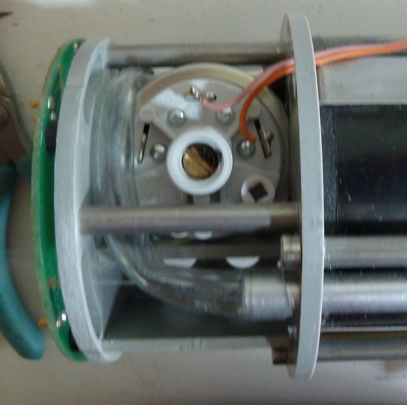
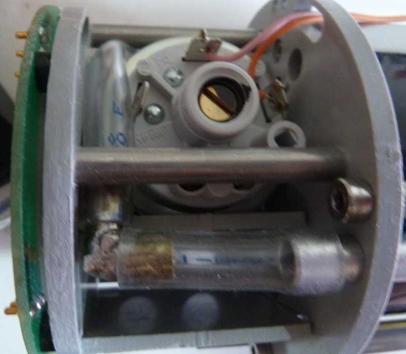
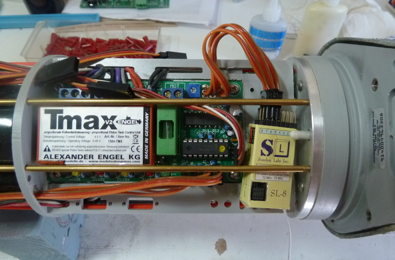
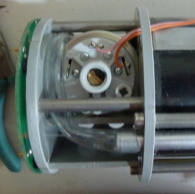
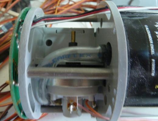
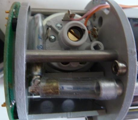
I am starting on getting all the pressure lines checked and had to do some work on the forward piston tank water line. It is a very tight area to run the tubing and there are kinks at both ends. The max depth pressure sensor is located in this area and it is quite big. There is barely enough room for the 10mm od tubing to fit. This is the connection to the outside water pressure. The aluminum tube runs through the rear bulkhead and is open to the sea. Note the kink. This picture shows the connection going to the forward ballast tank. Note the small kink in this line. I am not to worried about this kink but I will be sending an email to Engel with some pictures to see if there is a better way. I solved one kink by making a right angle fitting out of 1/4 thin wall brass tube. It still needs to be cleaned up a bit. My soldering leaves a lot to be desired. I may have to do this to the other connection at the ballast tank. Next problem to solve is getting in the tubing for the pressure sensor itself. The second picture shows the nipple on the sensor. The tubing runs through the hole to the other side of the bulkhead where there is a brass tube that runs to the rear bulkhead and is open to sea water. BTW, the pictures show a green phenolic ring that is attached to the forward bulkhead. This ring has a set of spring loaded pins. I have the bow plane servo wires going to a specific spot on the ring which matches another ring deep within the hull. This is the way the connection to the bow plane servo is made and still maintain water tight integrity. Enjoy the holidays. Until next time, IR3
-
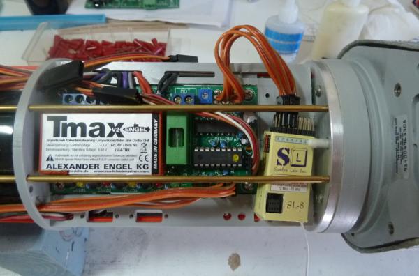
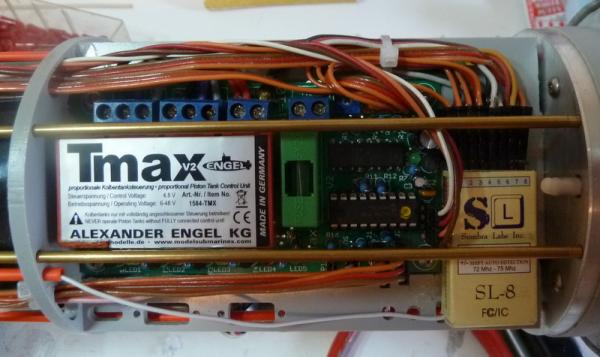
It has been a long time since I posted so here is an update. The TMAX2 came back a while ago and has been installed. It appears that the fixes are right on. Both piston tanks are working properly and the TMAX2 functionality seems to be OK. There is a lot to learn about the TMAX2 and its various modes. There is also a depth controller, the TAES, and I have a bit to learn about that. When I started hooking all the leads back on to the RX I began by using the old wiring scheme. A bit of a senior moment. Having pulled out what little hair I have left, I consulted my thread to see what I had done only to discover that the RX was moved back into rear bulkhead area. Getting old sucks! For things to do now, I will be getting the wires neat once again, make sure there all openings in the rear bulkhead have something attached or plugged and work to get the sub to neutral buoyancy. This will also be a good test for water tight integrity and checking that the ballast tanks are working properly. Until next time from the bottom of the pond, IR3
-
Hi Roger, A beautiful model. Yes, the kit does have it's sizing errors but you have handled them quite well. Your build will be a very nice tutorial for anyone that is planning to do this model. Best of luck on your next project, Iran
-
Hi Roger, I fantastic solution to a very perplexing problem with this kit. Can't wait till the next installment. Cheers, Iran
-
Hi Rodger, Bending the 1mm sq was a nightmare. Once again, I think I was fortunate that I had material that was accurate and pretty straight grained which helped quite a bit. The wood that was not straight grained had a tendency to start splintering. If the splintering was not severe, while still quite wet, I used some CA to smooth the splintering out. It did not stain as nicely as I would have liked but one had to take a very close look to see it. My problems with the stanchions was similar and I attributed it to slight differences in the width of the decks. Keep up the great work, Iran
- 94 replies
-
- 1
-
-
- robert e lee
- amati
- (and 1 more)
-
Hi Roger, The 1mm sq trim on the filigree was a bit of a headache. That was about the only wood in the kit that was cut accurately. The strips were soaked for a long time in water + ammonia to get them good and soft. To bend them, I had the luxury of bending iron that Luthiers use for shaping parts when building musical string instruments. I built a classical guitar around that time and the bending iron was the perfect tool for the filigree trim.The iron gets hot enough that the water in the soaked wood turns to steam and further helps the bending process. I did break a few but it all eventually worked out. As far as the vertical posts are concerned, welcome to the Amati Robert E. Lee. It falls under one of the dimensional problems that I think was never solved. It was a problem on both the models I built in the past. Don't let that little idiosyncrasy hold you up. Your build is excellent and the posts will not be a distraction to anyone but you. :) Looking forward to more updates. Cheers, Iran
-
Hi All, It is a time for reckoning. My Confederacy is just sitting gathering dust. I keep saying to myself that I should get the first planks on and enjoy the rest of the build but it just is not happening. My strongest interest lies in Submarines, Merchantmen, Fishing Trawlers and several steam projects. The hull is still straight after all of the problems I had earlier in the build. I am up to the step after planking the transom. The next step is to put the batten in to get ready for the upper planking. I would like to see this get into the hands of someone who will take the time to finish this model. I think I did a fair job on the hull so far and to carry on I believe would take very little effort as far as truing the hull. I even have the boxwood in all sizes that I substituted for the kit wood. If anyone is interested, please let me know. You can get this for a lot less than the price of the kit itself. Thanks for all of the support, IR3
-
Hi Ian, Thanks for the comments on the build. The sub is 78" long and just fits in the SUV with both the passenger front and back seats down. The Tech Rack is quite long at 46 inches and is completely packed. It is a big challenge to get it built and as I have been advised, a bigger challenge to get it trimmed once in the water. IR3
-
The TMAX is in the post back to Germany for evaluation/repair. It will probably be around 3 weeks before I get it back sot the sub is on the back burner for a while. BTW, thanks for the likes. It is very helpful getting me through the trials and tribulations putting the sub together. It is very difficult to get add ons installed with the extremely limited space. The design is excellent for the space and size of the sub and the electronics are probably way beyond what is needed but Engel thought of everything. It will get finished and hopefully no more gotch yas.
-
The problem has been solved concerning the forward ballast tank problem. The spindle screw (attached to the ballast tank piston) extends but does not retract. The problem appears to be in the TMAX. I tried running the forward ballast tank using the connections for the aft tank. It works perfectly both extend and retract. Both of the ballast tanks fail to operate properly when connected to the forward connections. It appears that the TMAX is not reversing the voltage when switching to surface on the forward connections. I have been in constant contact with Engel but just informed them about the problem with the TMAX. We shall see how this works out. Until next time, IR3
-
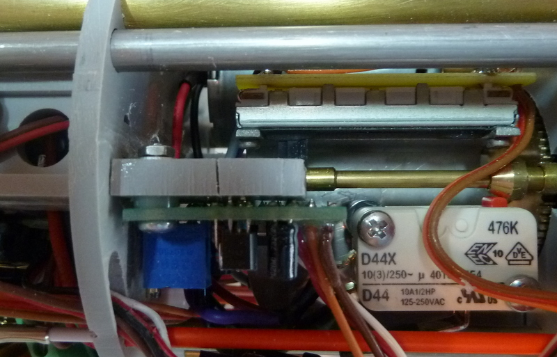
After disassembling most of the Tech Rack the problem was found. The mechanism that operates the linear pot on the ballast tank was colliding with the TAES (static depth sensor that works with the ballast tank controllor) shelf preventing full movement to the limit of the pot. Problem. The myopic senior did not mount the TAES properly. The culprit: TAES mounting shelf collided with linear pot mechanism preventing full extension. The Fix: Notch out the shelf and relocate slightly to accommodate the TAES without interfering with the WTC tube. Result: linear pot in fully extended position with no interference. Now I need to reassemble the Tech Rack. Until next time, IR3

-
Well, first the bad news , then the good news , then the bad news . With everything wired up and ready for testing I forgot to program the RX to the correct channel . Also, I wired the RX backwards so Ch-8 was plugged into Ch-1 , etc. By doing this the programming socket for the RX was face down . The good news is that once I programmed it and rewired the servo leads, most of the functions started working correctly . For the bad news, the aft ballast tank lead screw is binding either on the aft bulkhead of the battery pack or the forward bulkhead of the servo tray area. It is impossible to see what is happening with the servos in place and the battery pack hardware getting in the way . I need to pull the Tech Rack apart to try to find the problem. Of course, now it is greatly simplified since all the wiring now goes aft so it is just a bunch of screws and bolts, Another problem is that the forward ballast tank lead screw is not moving at all . Hopefully this is just a bad connection in the servo lead. More on that after the main problem is solved. Until next time, IR3
-
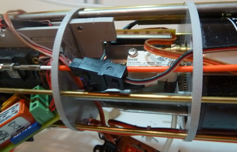
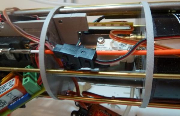
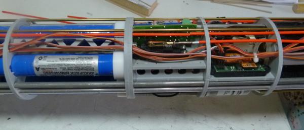
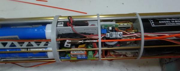
The rewiring is complete. It is extremely tedious since there is no extra room anywhere to tuck leads in that are too long. Each extension had to be cropped to the correct length. There is very little room since the leads have to pass between the WTC tube and the ballast tanks. Preparing the new connectors is no simple task either. Next step is to charge the batteries and start doing all of the static checks. First Pic shows RX temporarily in place. The next three shows how the wiring has been simplified and clutter reduced to a minimum. The antenna lead runs the length of the WTC in a piece of red tubing as seen in 4th picture. Until next time, IR3
-
Hi Mark, Shielding was considered at one time. It was difficult enough to get the wires through all of the slots without the shielding. It was pointed out by several Type VII/C builders that in any case, putting the RX at the fore end of the Tech Rack was absolutely a poor idea. Because of the compactness of the Tech Rack there were very few options as I pointed out. The only reason I am putting the RX next to the rear bulkhead is that the RX sill not suffer any interference from the Brushless motors and the servo leads to the ESC's have noise suppression Ferite cores plus the cable lengths will be extremely short. The best of all worlds. So far I have removed nearly 18 feet of cables. The chances for glitches in the new setup will be quite minimal, I hope. Iran