CDR_Ret
-
Posts
654 -
Joined
-
Last visited
Content Type
Profiles
Forums
Gallery
Events
Everything posted by CDR_Ret
-
 Need some help interpreting what I am seeing here. In the attached photo of Galilee's middle deckhouse port side, there is evidently a sliding door mounted on wheel tracks top and bottom. Here are some questions: How was such a door made reasonably weatherproof? Would there be water stops built into the frame to prevent major water intrusions during boarding seas? Would the door handle/latch be a lever or just a hand grab like a staple? As you can see, the photo is pretty muddy where a handle would be. There is a suggestion of a vertical metal rib along the forward edge of the doorway, which might be a water stop. Like all sliding doors on ships in my experience, there was probably a standing latch when the door was fully open and a latch when it was shut. I have no idea if technology of the late 1800s would have produced a mechanism that would operate both latches. If anyone has reference photos or other images of such an installation, I'd appreciate seeing them. Thanks. Terry
- 11 replies
-
- 2
-

-
- 19th century
- Galilee
- (and 6 more)
-
DelftShip ship design software
CDR_Ret replied to lehmann's topic in CAD and 3D Modelling/Drafting Plans with Software
Hi Guy. I regret to say that right now I am wrapped up doing a bathroom renovation and haven't put any time into this project for several months. I am hoping to get back to the planning and research in February. Terry -
I, too, read Nordhoff/Hall's trilogy in high school some 50 years ago. Bligh came across as a villain, though one had to acknowledge he was a consummate navigator. Christian was the beleaguered-but-competent first officer who finally had had enough. But then I recently read Bligh's journals that covered the Tahiti voyage, the mutiny, and the return to safety, which are available from various sources on the web as well as distilled versions in paperback. I came away with a totally different opinion of the man. According to these sources, he detested corporal punishment, and if anything was too lenient with his crew. The narrative pertaining to Christian in Bligh's words paints a disturbed, insolent, and insubordinate individual who chafed under any kind of discipline. Yet Bligh repeatedly gave him the benefit of the doubt and overlooked punishable offenses (and this may have given Christian the courage to go through with the mutiny). One could suggest that Bligh wrote his journals to favor his viewpoint and prejudice the crew's, but that hypothesis doesn't really ring true. Bligh is detailed in all of his entries, and at the time he made the earlier ones, he had no clue a mutiny would occur later. His attempts to maintain discipline and his concern for the welfare of the crew are remarkable. Ventilating the 'tweendecks, collecting rainwater as often as possible so the crew can wash their clothes, and having the cook provide a variety of prepared meals to keep the crew's spirits up. The journals were hand-written in ink and could hardly be edited later on. Some reviewers believe we have only heavily revised and rewritten versions that tell the narrative Bligh wanted, but if that were the case, he must have had an extraordinary memory, because the details of his narrative fit seamlessly together. So, as is always the case, it's best to acquire your information on historical figures from a variety of sources in order to arrive at a balanced opinion. Terry
-
Alan, As I wrote in July, I spoke directly with the CSR at Dassault in MA on the phone. She confirmed the Vets deal, that no sensitive identifying information needed to show on the scan of the DD214 (e.g. SSN), and that the program was renewable annually at the same price. Unless she was talking through her hat, I think it's legit. Haven't tried to obtain it myself because my main bathroom is torn down to the framing right now, but I plan to someday. Terry
-
I spoke with a Solidworks CSR on the phone a few days ago. She said that the $20 student version for Vets is renewable annually for the same $20 price. Also, Canadian vets get the same deal by providing a copy of their NDI 75 or CAF 75 cards. I expressed my concern about supplying my Social Security number on the DD214. She said that you can redact any sensitive PID (e.g., SSN) on the DD214 or other ID cards. All they need is confirmation that you served, were discharged, and that you are who you say you are. Terry
-
Drawing with quota, exist?
CDR_Ret replied to Jhenrique's topic in CAD and 3D Modelling/Drafting Plans with Software
Not sure that, in the absence of evidence to the contrary, we can assume that backfitting geometric rules to extant plans will automatically yield what the original designers had in mind. We know from historical writings that the Greek architects used the Golden Mean for designing their temples. But I suspect that in the early days of designing ocean-going ships, the forms developed based on regional perceptions of what worked and what didn't. And a lot of the designing was done on the building ways by eye and experience, not by compass and straight edge in the loft. Later on, when marine underwriters and governments began establishing rules for insuring and taxing ships and their cargoes, the designs shifted to maximize real cargo capacity while minimizing the tonnage under the rules. This approach resulted in designs that no geometer would have been proud of! Terry -
Bilge Pumps 1870/80
CDR_Ret replied to GAW's topic in Discussion for a Ship's Deck Furniture, Guns, boats and other Fittings
Very nice work, Gerald. Metal can be even more unforgiving than wood at times. If you would like to read an entertaining contemporary rant against this kind of vessel, take a look at the book "The Progressive Ship Builder, Vol. 1" by John W. Griffiths (1875). The book is available from Google books in various eBook formats for free. He was all about staying with wooden vessels or, if we have to go to iron, then making them double-hulled. He also rails against the Lloyds vessel classification scheme at the time. Terry -
Drawing with quota, exist?
CDR_Ret replied to Jhenrique's topic in CAD and 3D Modelling/Drafting Plans with Software
Jhenrique, With reference to modeling in 3D software, DELFTShip is a free naval architectural 3D drafting program. You can import a table of offsets provided from good references or you can construct a 3D model from scratch referring to three standard plan views. Search this forum for references to "DELFTShip" for discussions on how to do that. Terry -
This is in the FWIW category... The Curator of Navy Ship Models at Carderock provides the following guidelines for details to be included in their museum-quality models. Under Durability of Materials|Range they make the following statement: Generally, all items on the prototype twelve inches or larger for 1:96 scale (six inches or larger for 1:48 scale) will be reproduced. I suppose you can continuously scale the detail sizes in relation to these two standards. In the end, we have to decide what we are making the model for and with what we will be satisfied. Terry
-
Just ran across this thread. It got me to thinking about whether the remains of my grandfather's brigantine Galilee were still visible in the mud in Sausalito, California. As it turned out, they are in Google Earth. I verified this with the Galilee Harbor Community Association management today. Load the KML file in the zip file attached. You will need to have the free Google Earth program installed to view the timbers. Enjoy. Terry Galilee Final Resting Place.zip
-
Thanks for the input, but I serendipitously obtained my answer from a completely unexpected source yesterday. Last week, I began a series of inquiries with the San Francisco Maritime National Historic Park (one of the parks under the auspices of the National Park System, or NPS) which houses the stern of the Galilee as an outside exhibit at Fort Mason. In the process of asking about the feasibility of having someone from the local modeler's group do some direct measurements on the stern (there wasn't), NPS informed me that they were finalizing the production of a file of Galilee for entry into the Historic American Engineering Record (HAER) maintained by NPS. The engineer involved sent me draft copies of all the plans he is developing of the stern as well as a full history of the vessel from construction to present. This was truly a windfall of information. One key drawing is an elevation cross-section of the stern, which clearly shows the main deck extending to the transom, as well as the poop deck above it. The narrow space between the decks was used as a lazarette. The main deck also had a hatch to the lower afterpeak area above the keel. So this is another piece of data to aid in reconstructing the vessel. Even though the main cabin no longer exists, it's pretty clear it rested on the main deck as with the C.A. Thayer. The poop deck was provided only to elevate the steering station so the helmsman could see over the cabin and to make main spar sheet tackle more accessible. Terry P.S. Since the NPS drawings are only drafts, I felt it would be inappropriate to post them here until they are publicly released.
-
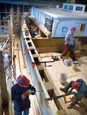
As I am moving into the details of deck furniture, deck houses, and the poop and forecastle decks in Galilee, it occurred to me that I had no idea whether the main deck in a basic sailing merchant ship extends the full length of the hull, including under the poop and forecastle decks. The remains of Galilee's bow at Benicia Historical Museum suggest that the main deck was planked all the way to the stem. But what about at the stern? Galilee had a low poop deck about 4 feet above the main deck surrounding the aft end of the main cabin (see photo below). The helm and main boom traveler were located right aft and the companionway to the captain's cabin was via a short stairway from the poop deck to the cabin deck, which appears to be at the main deck level. So, did the main deck planking continue aft to the fantail under the poop deck? I found a photo of the lumber schooner C. A. Thayer in San Francisco during her recent renovation showing what appears to be workers standing on the main deck while reinstalling the aft cabin and constructing the poop deck framing (see bottom photo). Would this be typical of merchant vessels c. 1900? If so, what was the dead space under the poop deck used for? Was this part of the lazarette space? Terry

-
Late 19th Century Merchants: Antifouling Paint Over Copper?
CDR_Ret replied to CDR_Ret's topic in Nautical/Naval History
Good stuff, John. That information was the gist of what I was able to glean from several sources. I found the attached document especially helpful. Combined with the film characteristics mentioned earlier, I'm going with the red bottom (when the time comes). At this point, it looks like I need to go back to do some more work on the ship's main rail run and transom moulded outline—a never ending story. Terry Marine_Antifouling_c 11.pdf -
Late 19th Century Merchants: Antifouling Paint Over Copper?
CDR_Ret replied to CDR_Ret's topic in Nautical/Naval History
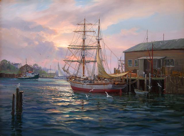
New info provided by a photographer friend might be of technical and historical interest. The best black and white film used around 1900 was called orthochromatic film. It was sensitive to blue and green/yellow light but was blind to red light. So red would show up in images as nearly black. Green would be a shade of gray. Based on this information, I suspect the hull in the dry dock photo probably has red paint. Earlier film before 1884 was sensitive to mainly blue and UV light. Panchromatic films sensitive to red light were available in the 1890s, but only on glass plates manufactured in Germany. Based on my grandfather's diaries, and the arduous nature of the geomagnetic field work, I suspect DTM/CIW required the use of emulsion film, which was available only in ortho- or isochromatic form. Attached is another Vickery painting showing Galilee in a red hull. Terry
-
Late 19th Century Merchants: Antifouling Paint Over Copper?
CDR_Ret replied to CDR_Ret's topic in Nautical/Naval History
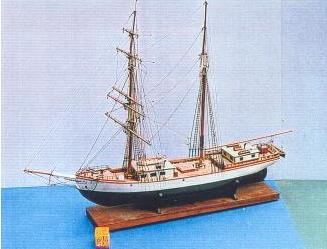
Also, I have in my files this painting by Charles Vickery, who was well known for his accurate rendering of marine subjects. It shows Galilee in the foreground with green bottom paint. The model of the Galilee that was offered by his gallery also shows a green bottom. So I'm inclined to go with a dark green. (The model was more of an approximation than true to scale. There are many discrepancies in the details compared to the actual vessel.) To be completely objective, he also painted Galilee with a red bottom, so perhaps the color doesn't really matter.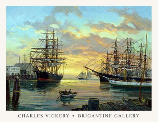
-
Late 19th Century Merchants: Antifouling Paint Over Copper?
CDR_Ret replied to CDR_Ret's topic in Nautical/Naval History
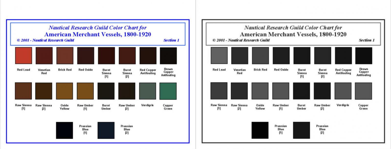
John, I suspect you are correct, but I wanted to get a second opinion on the bottom covering. The only two U.S. West coast ships I know of that are contemporaries of Galilee are the Balclutha and the C. A. Thayer, both located at SFMHP. Photos of their restorations show them with the dull red bottom paint. My concern is that in the 1907 photo, the paint looks darker than might be the case with the red lead. Attached are images of NRG sample paint chips for vessels of this era; one is colored and the other in grayscale. Not sure of the color response of the original film, but the grayscale chips suggest a darker color. This is why I could use some Pacific West Coast expertise before making any decisions, granted that this step is pretty far down the pike at this point. Terry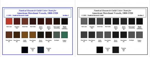
-
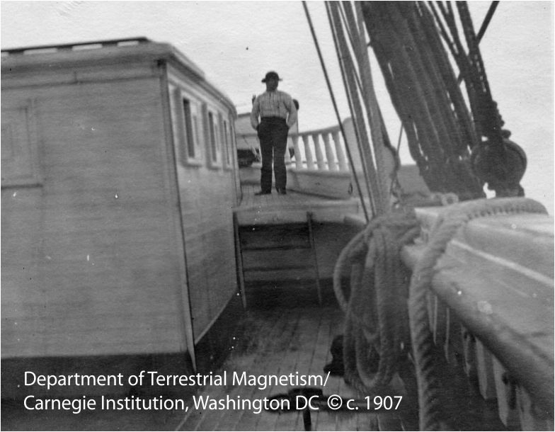
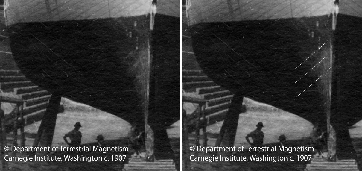
Pertaining to my research on Matthew Turner's Galilee, I have a drydock photo of her taken on the bow. A very nice reference photo, even if it's in B&W. (See the detail below.) The image is grainy, and the hull below the boot top is mostly in shadow, but there are some curvilinear shadows near the bow that suggest copper sheathing rather than just planking. The right-hand image indicates what I am referring to. But this doesn't make sense, since the bottom clearly has been painted. So, are those lines just unfair hull planking or copper plating that has been painted over? My research turned up a history of antifouling methods, and it claimed that vessels employed in the tropics relied on copper to keep the worms at bay. Since Galilee was used in the San Francisco to Tahiti trade before her employment with DTM/CIW as a research vessel, It's likely that she was coppered. Anyone have thoughts on this? As an aside, what would be the likely color for the bottom paint for a West Coast sailing merchant c. 1890-1910? Terry

-
DelftShip ship design software
CDR_Ret replied to lehmann's topic in CAD and 3D Modelling/Drafting Plans with Software
Larry, I stand corrected on the 'Bama. That would make a more interesting (and challenging) model to work on. If you are going to model directly on a drawing, you still need a spreadsheet or table with offset-like (x, y, z) intersections to enter into the control net point editor. Otherwise, you will end up with a 2D model. My suggested sequence to start this project DELFTShip would be the following, though this isn't the only way to proceed. Create separate profile, plan, and body view JPG files, all at the same scale. You will need a photo editor to do this. Make them as high resolution as you can (300+ dpi). Create a new project in DELFTShip. I don't have the program in front of me right now, but I think you just click on the white blank page icon in the upper left corner. Follow the instructions and save it. The 7.X version of the program has a Windows-like ribbon. Under the Home tab, click on the Project Settings button. Fill in the General stuff as desired. The really important thing to get right at the beginning is the type of units used. Select either metric or imperial (English), according to your plans. If you forget to do this and leave it in metric (default), when you go back and try to switch to English, it does a dimensional conversion, not numerical. In other words, if you create a model 150 feet long in the meters setting, and then realize you want it to be in feet, and switch the units here in the Settings dialog, the model is now 3.281 ft/m X 150 m, or 492 feet long! All is not lost though. Just use the Scaling feature on the Tools tab and scale length, width, and height by 1/3.281, or 0.3047. Still in the Settings dialog, click on the Main Particulars tab and fill in the Length or LBP (distance between aft face of stern post at LWL to intersection of stem rabbet at LWL), Beam (maximum moulded width), and LWL Draft to baseline. Galilee's baseline was the keel rabbet line. You will need to determine your plan's waterline baseline for this data. The Mid-ship location is set by default at 50% of Length, but if you have a station at that point, I would select a position between stations. This item determines at what point the program splits the stations between the front and stern halves of the body plan view. It should correspond to your body plan image you will be using. You also need to select the Longitudinal reference point. It defaults to the midpoint, but many plans use either the AP or the FP for reference. Galilee's plan used its vertical stern post for the reference. (I recommend the AP because all x values will be positive forward of this point.) The rest of the settings are of little interest to the modeler (IMHO). I can't recall exactly, but I think there is a default model in the new project window. Just select all and delete the model. The next step would be to add the three images in their appropriate views. This is done under the Tools tab. The process is addressed under Section 3.4 of the manual, but it's pretty vague as to the order of operations to make the process reliable and straightforward. I need to be looking at the program to explain this, so it will have to wait. For Bruce, I think it was more the fact that I held an eagle feather in my left hand, and shook the rattles twice before clicking Accept that made the images go where they were supposed to. Some general hints on hull modeling from scratch: Building a model using a Control Net is not the same thing as drawing an image in 2D. You are creating a subsurface framework that influences the shape of the underlying surface but is NOT part of the surface except at its edges and at "creases". Read Section 3.1 for a (very) brief overview of this modeling method. If you have used Blender or other subsurface modeling programs, then this should be old hat. To create a surface, you need to first have at a minimum of 3 control points in different locations (see below).Then you have to select all the points that will be used to shape that surface. This is done by holding the Ctrl key down and selecting all the points one at a time (more control) or by band-boxing (less control). Then press the Add Face button (the manual's button doesn't agree with the program's here because the GUI was updated since the manual was published). Connect the control points with control lines as desired. This is done by selecting two or more points as above, then clicking on the Insert Line button. For more control, I usually do this with pairs of points, though you can generally do a string of them as long as they don't form an obvious polygon. Otherwise, you may have lines connecting all the points to each other. When you use the Add Point button on the Ribbon, it places the new point at the 0, 0, 0 location and displays the Point editor. To obtain a precise location, as with offset table coordinates, fill in the x, y, and z values in the point editor box. Note that x is positive forward of the longitudinal reference (a good reason to make it the AP), y is positive from centerline outboard, and z is positive from the baseline up. All coordinates are negative on the opposite sides of their respective reference lines. One last thing about selections. In the newest version of the program, clicking on control points with just the mouse deselects the previous point selected (selected points are highlighted yellow). Not so control lines and surface patches. Sequentially selecting lines and patches keeps all selected until you press Escape. I think there is a Deselect All button in the ribbon with the newest version, but I haven't checked that out. This bug can get you if you are trying to select edges to make them creases, such as along the edges of the keel or stern post. You end up toggling one edge to uncrease as you try to crease another if you don't unselect it first. Very annoying. I just noticed that the DELFTShip Free webpage doesn't have their latest manual available for download. You will need to send an email to Maarten Visser (maarten@delftship.net) at their site and request the latest (it should be "manual_714_282.pdf" or later and it's nearly 10 MB). If it's a later version, please let me know. Got to get back to work, but if you desire, I can elaborate on some of the other basic processes and features sometime later. Terry -
DelftShip ship design software
CDR_Ret replied to lehmann's topic in CAD and 3D Modelling/Drafting Plans with Software
Not to disagree with Bruce, but you can import separate images into all three standard views (see the attached image of Galilee when I was working on her stern). Not that it's easy to do so, and if you don't hold your mouth right, you can end up with all three images in one view! As Bruce said, you can import the model as a table of offsets. The manual describes how to do that, but it leaves out several gotchas and the terms they use for the different rows and columns in the text file are ambiguous. I would recommend starting your model this way if you have a CAD program that can display x and y coordinates for station and waterline intersections. If you try importing these into the program, it's going to look pretty messy until you create and designate the crease lines (edges where the curve of the surface is discontinuous). Considering you are doing an ironclad, I assume there will be a lot of those.
-
DelftShip ship design software
CDR_Ret replied to lehmann's topic in CAD and 3D Modelling/Drafting Plans with Software
Larry, I can help get you started. I'm still tweaking the final hull form of Galilee, but it's the getting started that is tough with this program. I would recommend downloading the free version of the DELFTShip program and manual from here. Be sure your system meets the OpenGL requirements. Read through the interface and hull modeling sections, and then I can walk you through setting up a file, inserting the plan images, and then building up the hull. It's not intuitive by any means, but once everything is in place, the actually modeling is pretty straight forward, and produces a cool result. PM me if you want to do this via email. Terry -
Chris, yes, the program is actually quite useful in that respect. You just set up the station spacing on the baseline to match the room and space (14 inches and 14 inches) of the original hull, and the forward and after moulded frame edges appear on the plans. The program projects the stations onto the modeled hull surface. They aren't fixed reference points that determine the hull shape or anything like that. I have a fairly accurate idea of the framing from direct measurements on the bow at the Benicia museum and the stern at Fort Mason in SF. Interestingly, Matt Turner didn't use cant frames, so the spacing problem is even easier to deal with. Druxey, by "fidelity" I meant "true to form", not necessarily structural accuracy. I'm not sure how many bulkheads you would need to avoid the inevitable flat spots between them if they are too far apart. I've carved a half-hull of Herreshoff's Gloriana using the lift method from WoodenBoat plans, so I'm comfortable with that. I could carve the moulded shape of the hull then plank on top of that. The result would be a pretty heavy model, though. Terry Greenville, South Carolina, USA
-
I am approaching the point that I will need to make a decision as to what technique I will use to build the hull: plank on frame, plank on bulkhead, or the lift method. My model is a fairly straight forward late 19th century brigantine merchant. Never having built a hull from scratch, I am willing to attempt any of these methods, but my greatest concern is ensuring the fidelity of the finished product. Anyone here have recommendations (preferably with explanations)? Thanks
-
DelftShip ship design software
CDR_Ret replied to lehmann's topic in CAD and 3D Modelling/Drafting Plans with Software
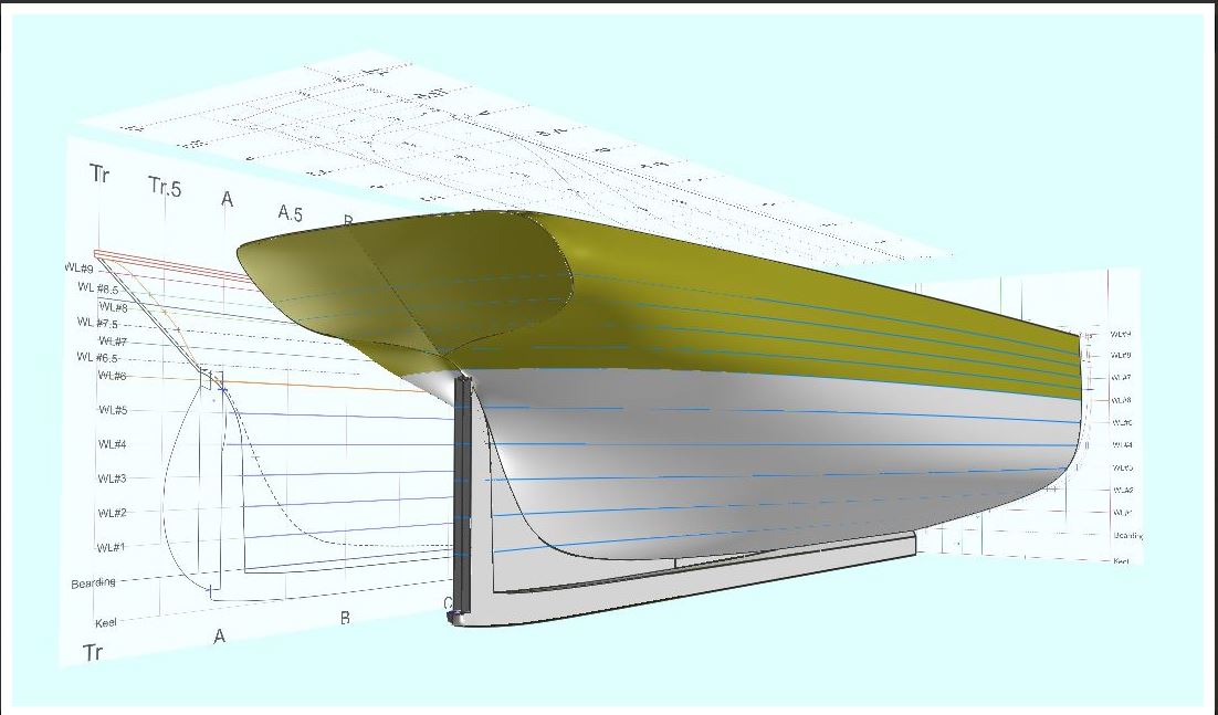
Good morning lehmann. Nice work with that CAD model! I've been using DELFTship Free for developing a set of plans for my brigantine Galilee project, which is featured elsewhere on this site. I must be dense, but the program was anything but intuitive to start a project in. The manual is only marginally helpful. After a steep learning curve, I'm approaching the point where I believe I have a reasonable hull. My reason for using the program arises from the need to correct the stern/transom shape of the vessel in the Smithsonian plans, which are the only existing complete set of drawings for the ship. I have a number of contemporary photos of the vessel that show a distinctively different shape. Chasing these kinds of adjustments around three 2D views is a frustrating task, while the consequences of making adjustments are immediately visible in a 3D CAD program. I'd like to see more modeler interest using this program. It has a lot of potential for identifying errors in plans before committing time and wood to the build. Terry