CDR_Ret
-
Posts
660 -
Joined
-
Last visited
Content Type
Profiles
Forums
Gallery
Events
Everything posted by CDR_Ret
-
 I tried to get Shapeways to print a Cold-War submarine 7-bladed screw from an STL file I created in Blender. However, at the scale I intended, the online evaluation tool said the blades were too thin. Anything thicker would have looked wrong, so I gave it up. Terry
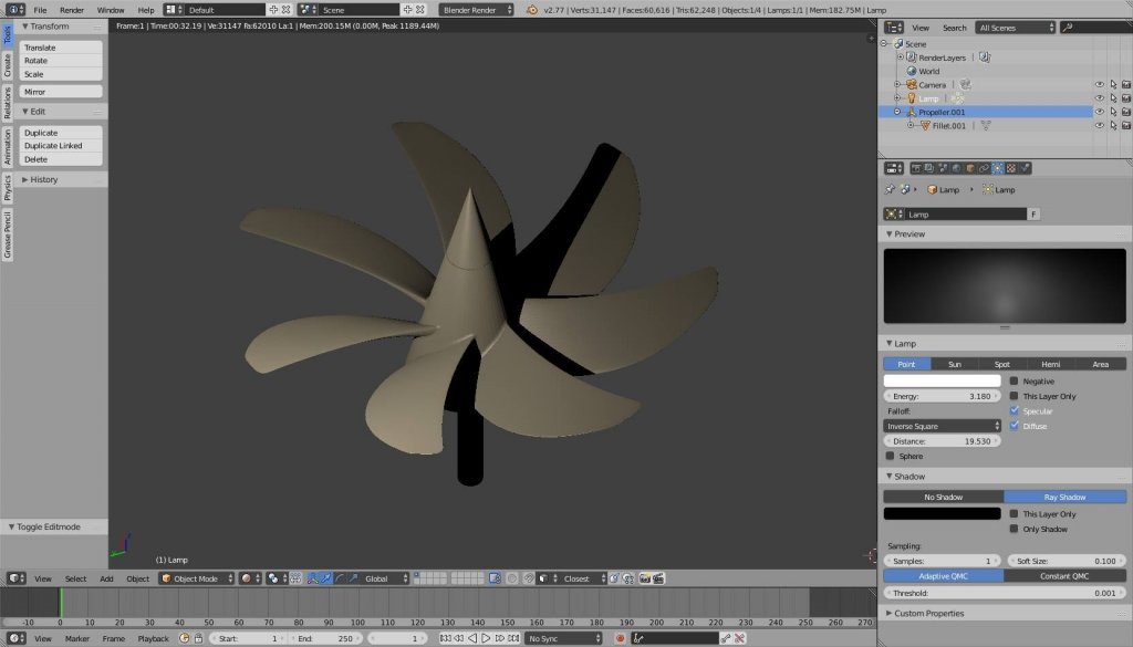
-
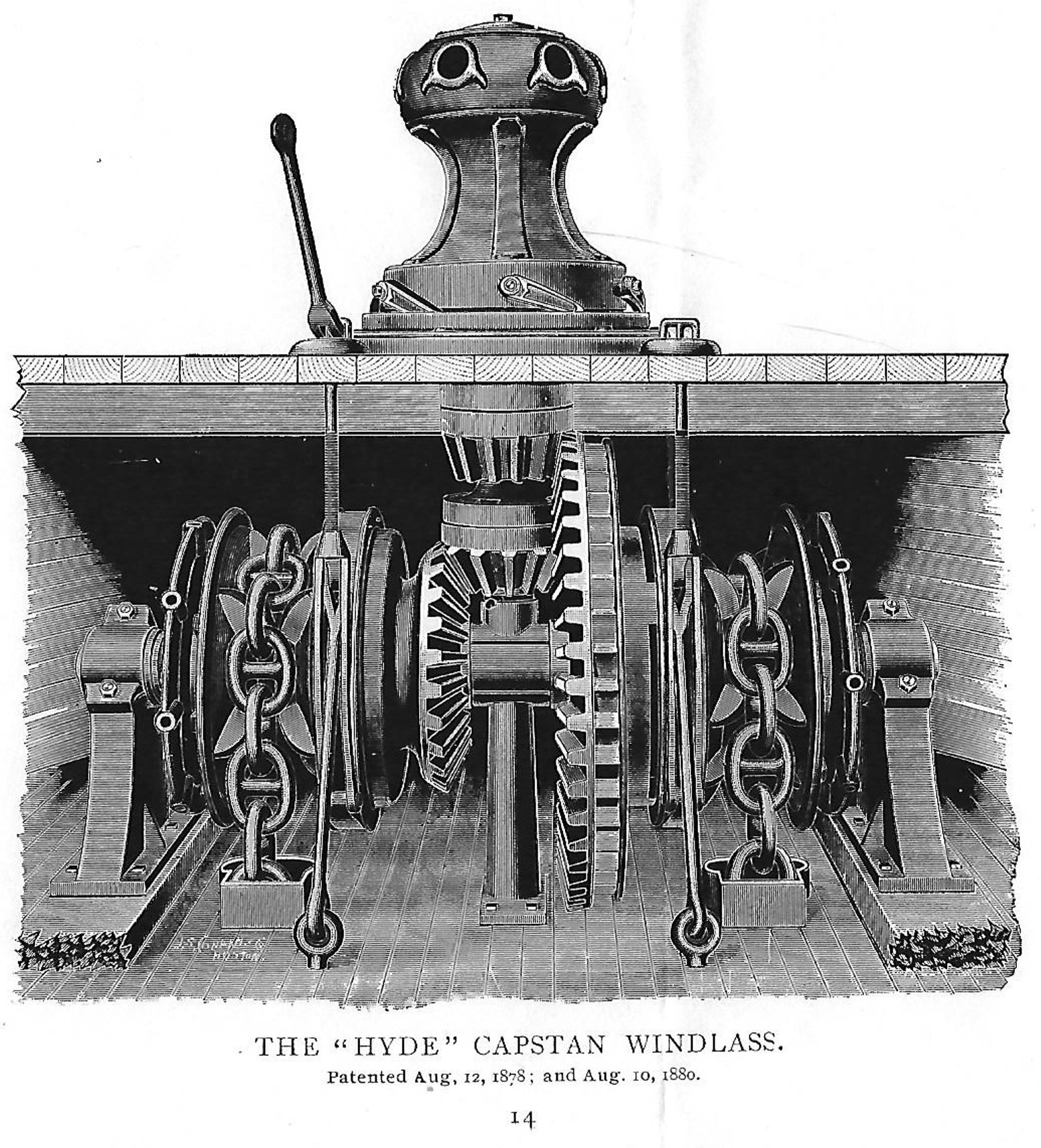
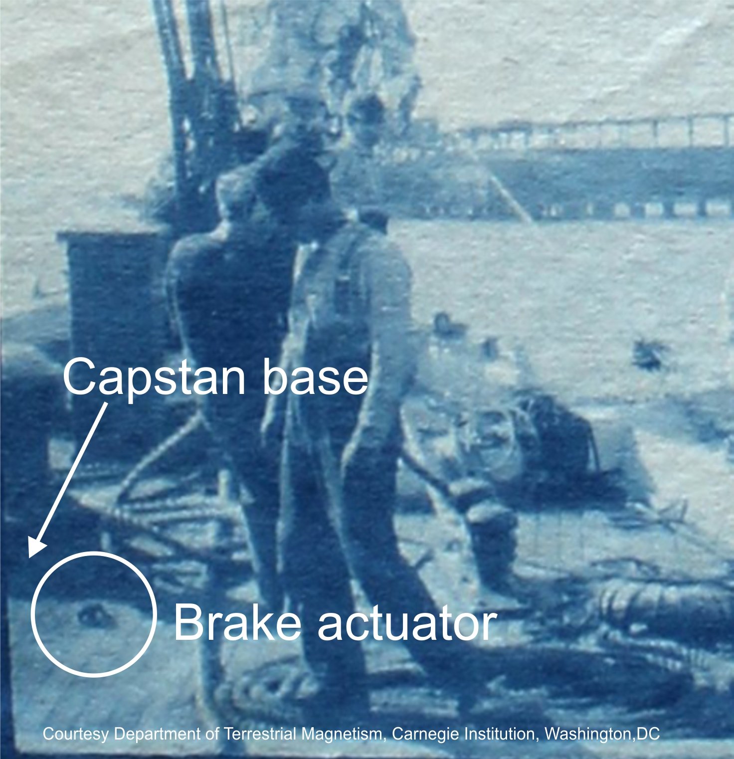
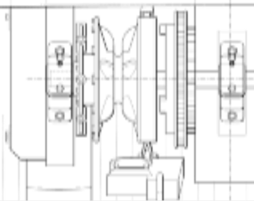
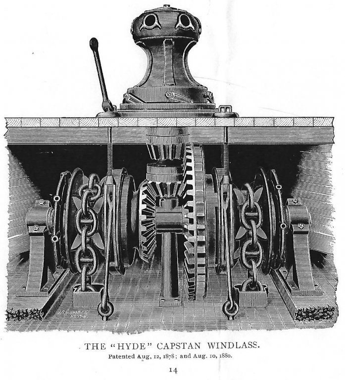
This past weekend, I received a packet from the Maine Maritime Museum*. It contained several scanned pages from a 1902 Hyde Windlass Company (HWC) catalog that related to their manual capstan and windlass machinery. Since the patents listed in the figure were several decades prior to the publication date, the design spans the time the Galilee was built, and is likely representative of the type she carried. This is the scanned engraving of the machinery from the catalog. Compare this design with the image in the previous post. The wildcat brake actuators consist of forked lever rods that engage the band brakes from the forecastle deck, rather than screw actuators mounted on the main deck as I drew them. It turns out that Galilee did indeed have this type of brake control, as indicated in the following photograph, which was taken in 1905 during her outfitting as a magnetic research vessel. I also discovered from this photo that the capstan was mounted on a base about 8–10 inches high. This is referred to in HWC catalog, so I will need to include that detail in the final plans. So I am now much more confident that I have identified at least a plausible anchor handling gear for this vessel, and can now move on to other deck furniture. Terry *Maine Maritime Museum contact information: Anne Witty, Chief Curator Maine Maritime Museum 243 Washington Street Bath, Maine (ME) 04530 Tel: 207-443-1316, ext. 328 Email: witty@maritimeme.org

- 21 replies
-
- 6
-

-
- capstan
- hand windlass
- (and 3 more)
-
FYI, Shapeways, the 3D printing company, shared an email today that lists five popular (and free) 3D drafting programs that you can use to create models suitable for 3D printing. They are: TinkerCAD Sketchup (good for creating deck furniture, rigging components, etc. Frames and planking are more difficult) Sculptris (a free version of Zbrush) 3D Slash (not recommended for ship modeling; too blocky) Ultimaker's Cura (checks models before 3D printing) And there are always Blender and DELFTship. These are also free, but their learning curves are pretty steep. Terry
-
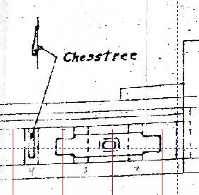
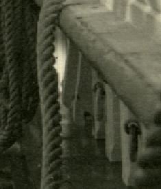
Hi Matle, The items you labeled "1" and "2" in your original post are probably chesstrees. These are vertical timbers of wood fastened to the inside surfaces of bulwarks (or frames) for the purpose of redirecting the tacks and sheets of the lower courses for belaying. Their designs appear to be quite variable. Some have sheaves incorporated into their upper ends. Others seem to be more like vertically-oriented, one-ended cleats, with the "thumb" of lower end used to change the direction of the line. They are described in The Art of Rigging by George Biddlecombe and in The Ship Model's Assistant by Charles G. Davis, as well as on-line. Davis's book includes a diagram of a typical chesstree found in a 17th-century sailing vessel. Matthew Turner's Galilee (also a late 19th century, West Coast merchant) had four chesstress on both bulwarks. The Smithsonian plans identify them and show a cross section, regrettably not very clearly. The photo below shows a pair of chesstrees on Galilee's port bulwark. Hope this helps answer your question. Terry
-
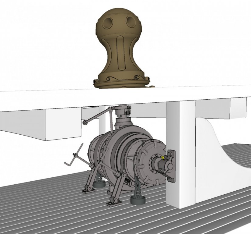
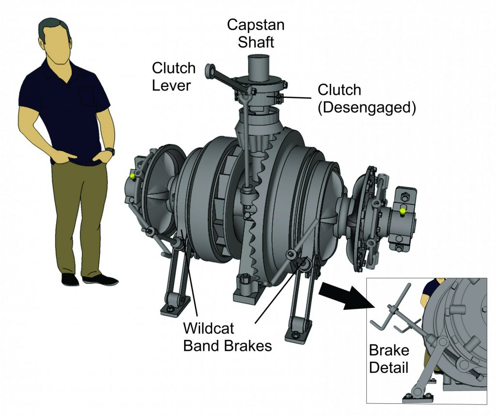
Aaannd .... here is the final image in this topic showing the capstan and windlass in the context of the forecastle space. Based on my reconstruction of the Galilee plans, there will be about 39 inches of room between decks, so I had to downscale the windlass machinery to fit. I also flipped the clutch actuator so that I could maximize the size of the rest of the equipment. The image seems tilted because the equipment rests on the extreme forward sweep of the deck sheer. There is a 4-degree slope at this point on the deck. Anchor chain comes up from the chain locker through pipes in the deck immediately below the wildcats and lead forward through chain stoppers (not shown) to the hawse pipes in the bow.
- 21 replies
-
- 3
-
-
- capstan
- hand windlass
- (and 3 more)
-
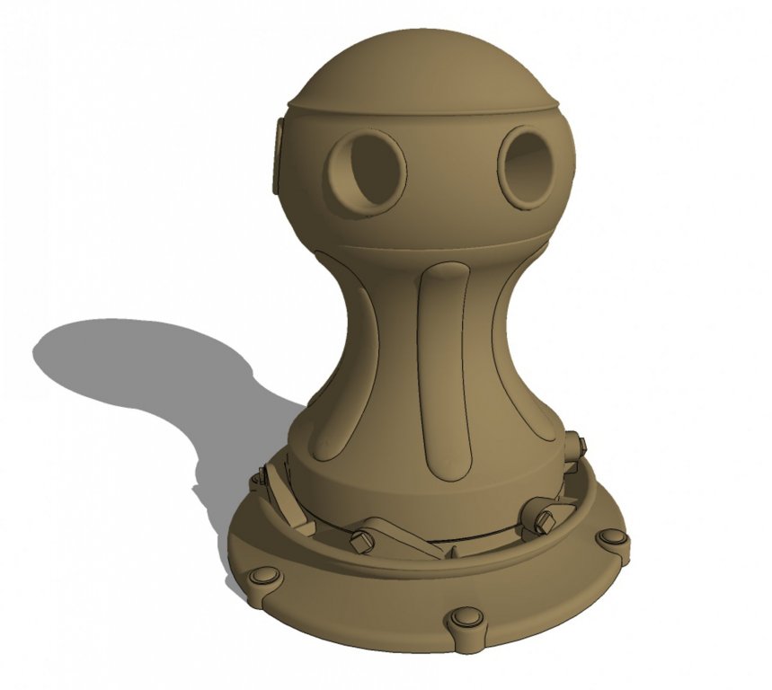
Here is my reconstruction of the Galilee's capstan, based on the DTM photo of the upper 2/3 of the actual capstan, with reference to a 1915 Hyde Windlass Company catalog and a random photo of another similar capstan I found on a photo sharing site. While Sketchup can support creating such models, there is a lot of fiddly mesh editing that is required, involving many hundreds (thousands?) of faces and edges. To minimize this cleanup, I created a clean version of a one-sixth sector of the capstan, then did a rotational copy five times to duplicate the sector, resulting in a complete model. The next step will be to marry the capstan to the windlass, then place them in context with the decks and structural members as they would have been on the ship itself. This will help me work out the details for framing in the vicinity of this machinery. Terry
- 21 replies
-
- 1
-
-
- capstan
- hand windlass
- (and 3 more)
-
I finally finished drafting up my reconstruction of a Hyde windlass that could have been installed in Galilee. It uses components from Hyde and windlasses found in ships contemporary with Galilee that served on the West Coast of the USA. Since the prototypes were found on ships larger than Galilee, I will likely have to scale this down to a size that will fit in her forecastle. I am hoping to develop a model of her capstan, then show the combined capstan/windlass machinery as it might have been installed in the ship, with appropriate timbers and decking. Oh yeah, and that band brake operator contains a true 2-inch trapezoidal ACME thread developed from ANSI references. Quite fun to make! So far, most of the major components have been separately built in Sketchup Make 2017, and are manifold, which means they could be 3D printed if desired. Terry

- 21 replies
-
- 2
-
-
- capstan
- hand windlass
- (and 3 more)
-
You are correct, Druxey . Never heard of the play Paul Pry I wonder if that is where the phrase "prying into someone else's business" came from?
- 21 replies
-
- 1
-
-
- capstan
- hand windlass
- (and 3 more)
-
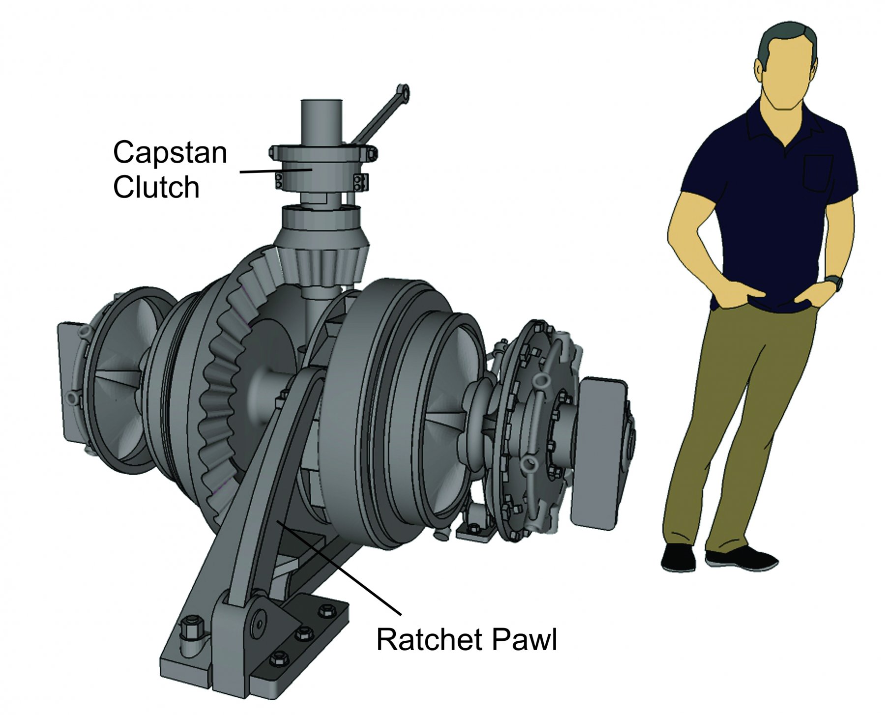
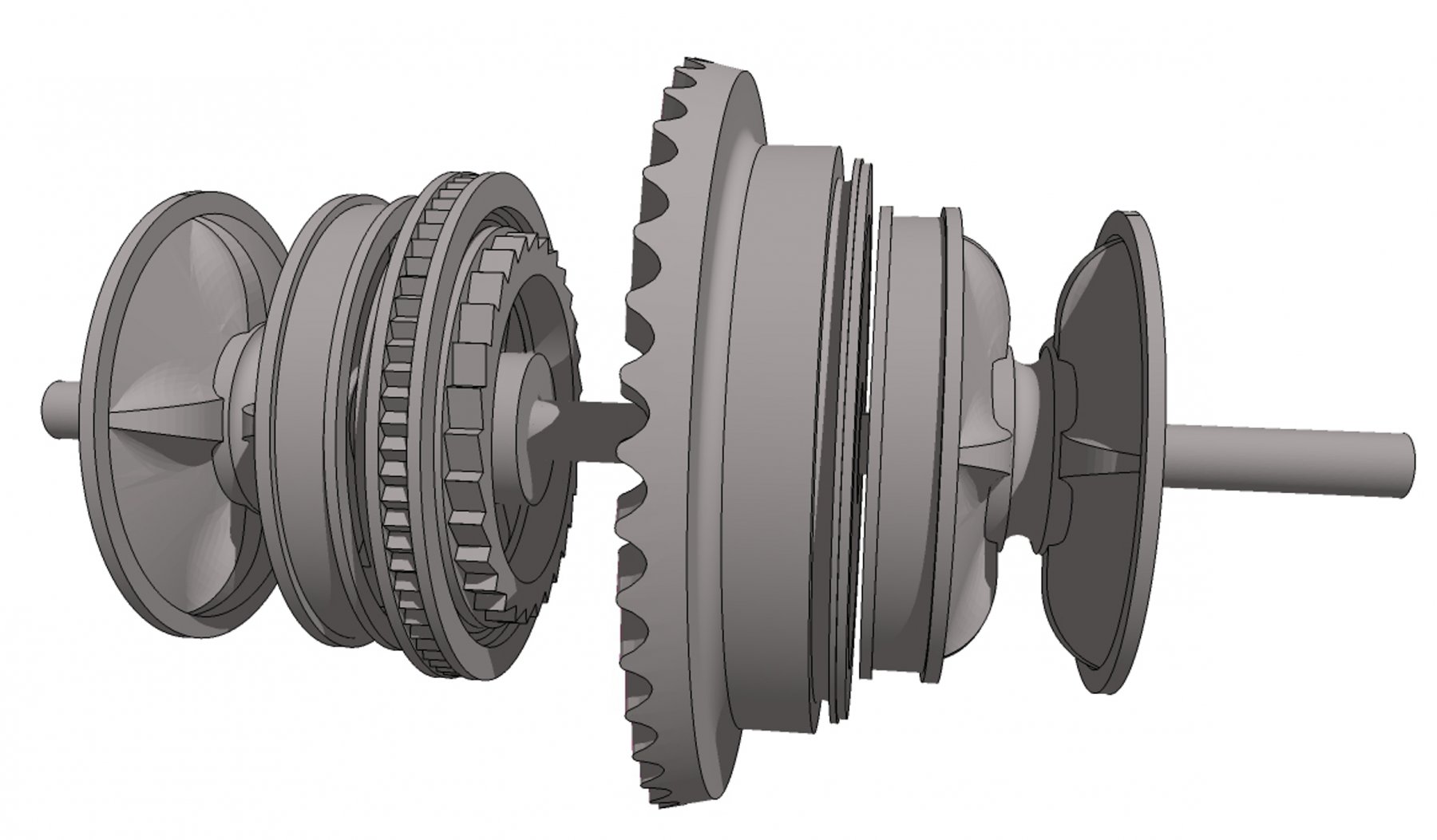
Update on my reconstruction of Galilee's capstan. I am three weeks out from a repair of a 25-year-old hernia repair, so I've been recuperating rather than sitting at a computer... (for you older guys, my surgeon informed me that redos of inguinal hernia repairs in men are quite common. The joys of aging!) These images show progress and corrections from the previous post. I have most of the key components modeled in Sketchup Make 2017. The only things left for the windlass are the controls (ratchet pawl, wildcat band brakes, and capstan clutch lever). I realized after the fact that the double pawl wheel shown previously was applicable to the lever-style capstan I was using as a reference. It has been replaced with just the windlass pawl ratchet wheel. Please feel free to ask any questions. Terry

- 21 replies
-
- 1
-
-
- capstan
- hand windlass
- (and 3 more)
-
Importing Images Into Sketchup
CDR_Ret replied to Billtoons's topic in CAD and 3D Modelling/Drafting Plans with Software
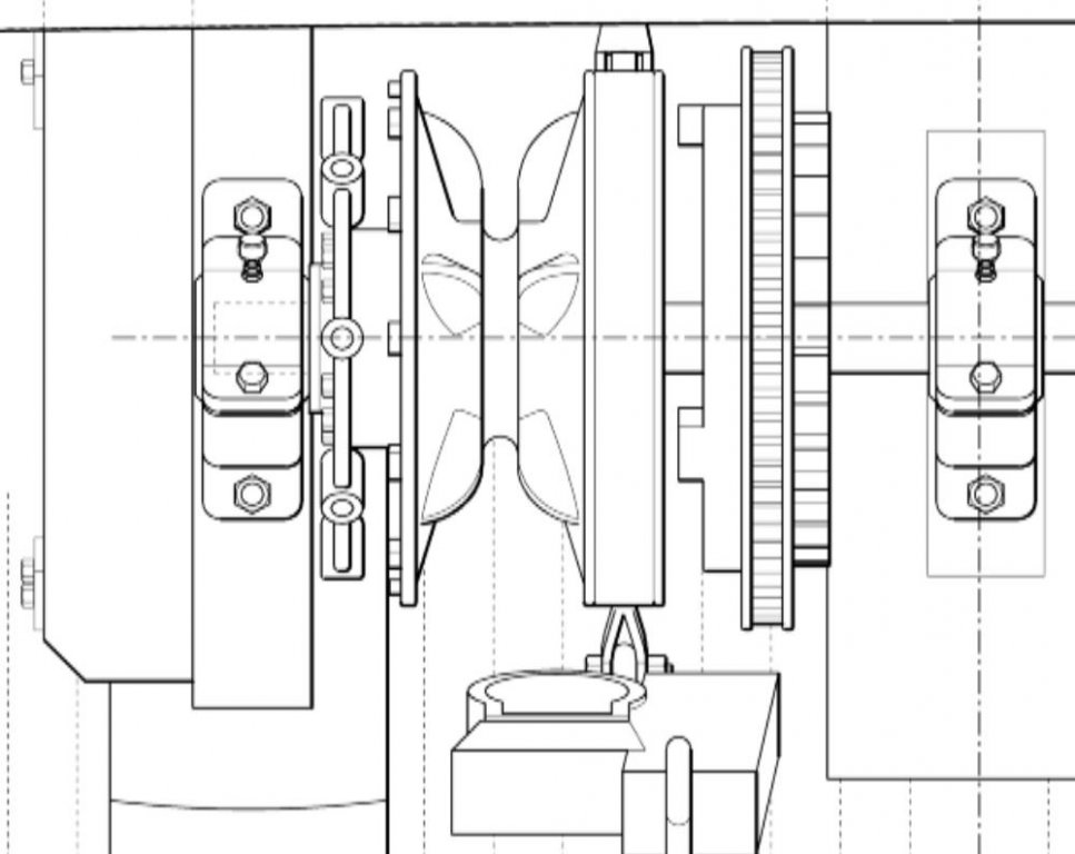
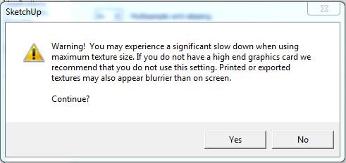
Note that Sketchup's default image import resolution is pretty low. To maximize the line sharpness of imported images, which is essential for tracing plan lines, do the following (applicable to Windows systems): 1. Navigate to Sketchup Preferences. (Window|Preferences) 2. Select OpenGL 3. Check Use maximum texture size. 4. Click OK. I included a screenshot of a windlass plan in the default and max resolutions so you can see the difference. These are rendered using a high-end graphics processor, so you can see that it is Sketchup that is affecting the appearance. Large images at maximum texture sizes will slow down the editing process without a good graphics card. See the Warning screenshot.
-
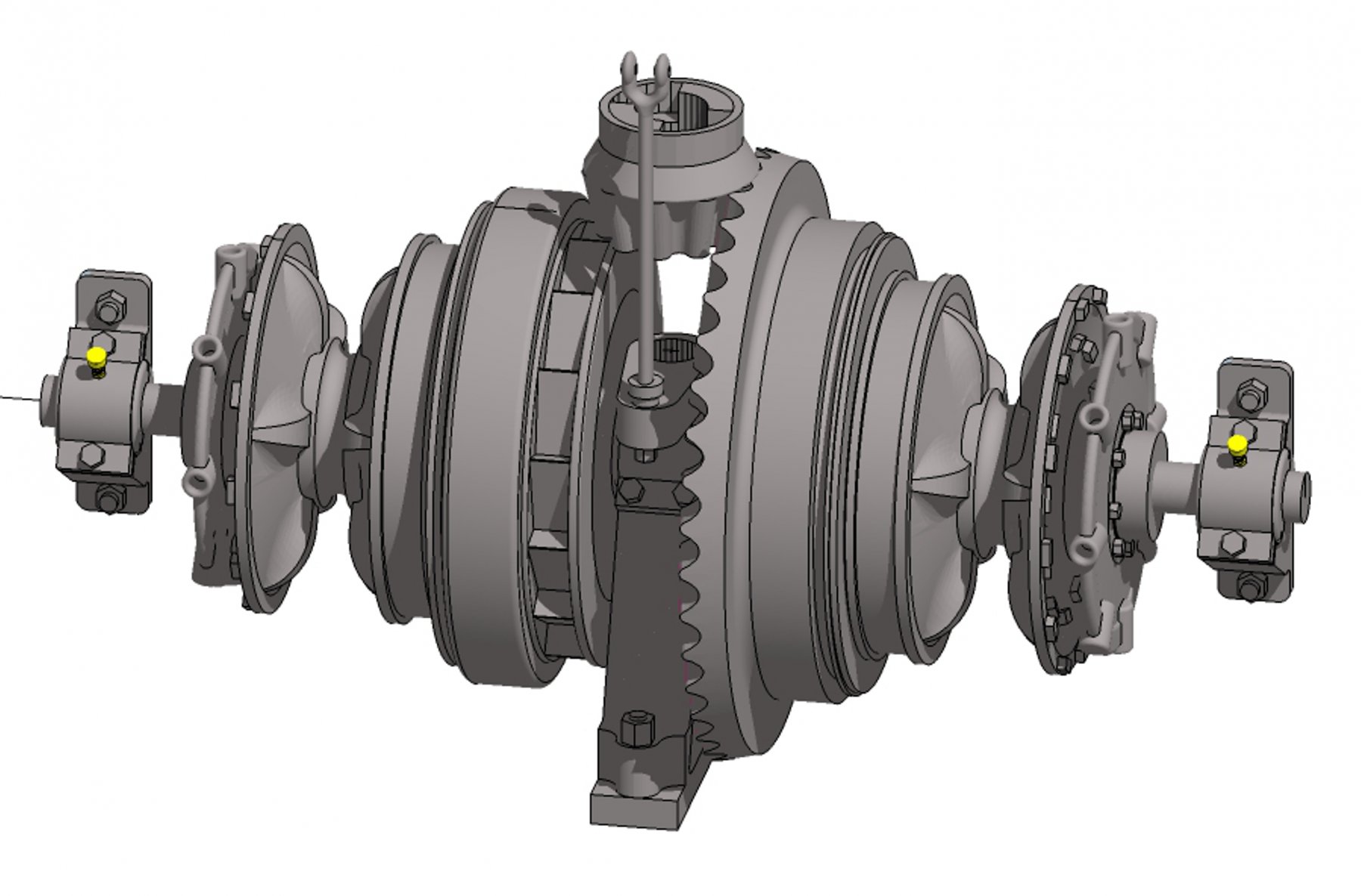
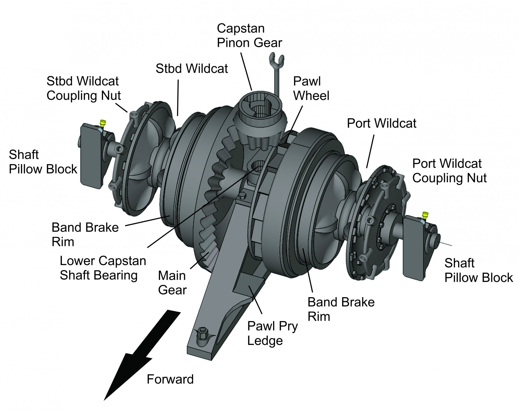
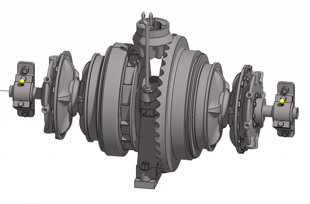
Here is the current status on reconstructing Galilee's windlass using the resources I have available. The diagram is constructed in Sketchup Make 2017 using the basic tool set. This part is probably the hardest to create, with all the curved surfaces in the wildcats and the crown gear. All that remains is creating the operating gear and the mounts to the ship's frames. I suspect that the windlass was mounted to the deck structural timbers, similar to the Lucerne and Thayer, rather than having a separate metal foundation like the Balclutha. I'm hoping that this will be 3D-printable, but the level of detail at the anticipated scale of the model will probably be lost or not printable. Terry
- 21 replies
-
- 5
-
-
- capstan
- hand windlass
- (and 3 more)
-
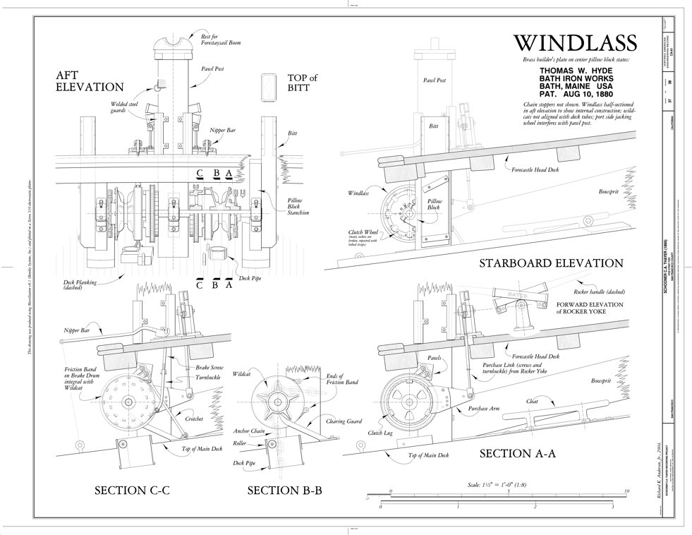
Thanks Roger—good call. Sadly, the Thayer's windlass is actuated by a rocker-type mechanism. It has a standard capstan forward on the forecastle, but there isn't any indication it is linked to the windlass. However, it is a Hyde windlass, so I should probably be able to pattern the wildcats and related hardware based on these drawings. It seems this type of windlass was bolted to a pair of bitts. However, Galilee had only one large bollard samson post located centerline and forward of the capstan. Evidently, the windlass supports were incorporated into the forecastle deck framing.

- 21 replies
-
- 5
-
-
- capstan
- hand windlass
- (and 3 more)
-
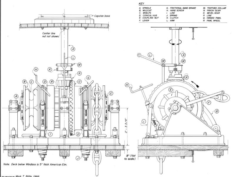
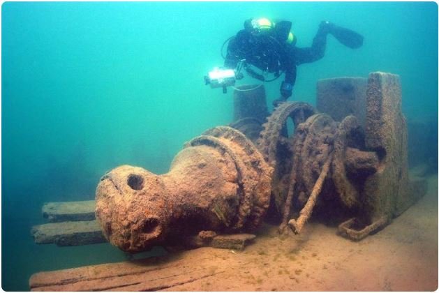
Took a few hours today to do a detailed search of the Web on this topic. The only things I came up with were the following. Balclutha, which is one of the premier museum vessels held by the San Francisco Maritime National Historical Park, is extremely well documented through the National Park Service HAER program. Several of the scale drawings in that program include diagrams of the anchor windlass, which is shown below. Though the Balclutha is much larger than Galilee, she is almost contemporary to the brigantine. The following diagram shows Balclutha's hand-powered anchor windlass. The photo below that I found on Pinterest of capstan/windlass of the sunken Lucerne (check out the Wikipedia article) is probably more similar to the one Galilee carried. Since there doesn't seem to be any contemporary diagrams available of a Hyde windlass, I'll have to approximate one when developing the ship's plans.
- 21 replies
-
- 6
-
-
- capstan
- hand windlass
- (and 3 more)
-
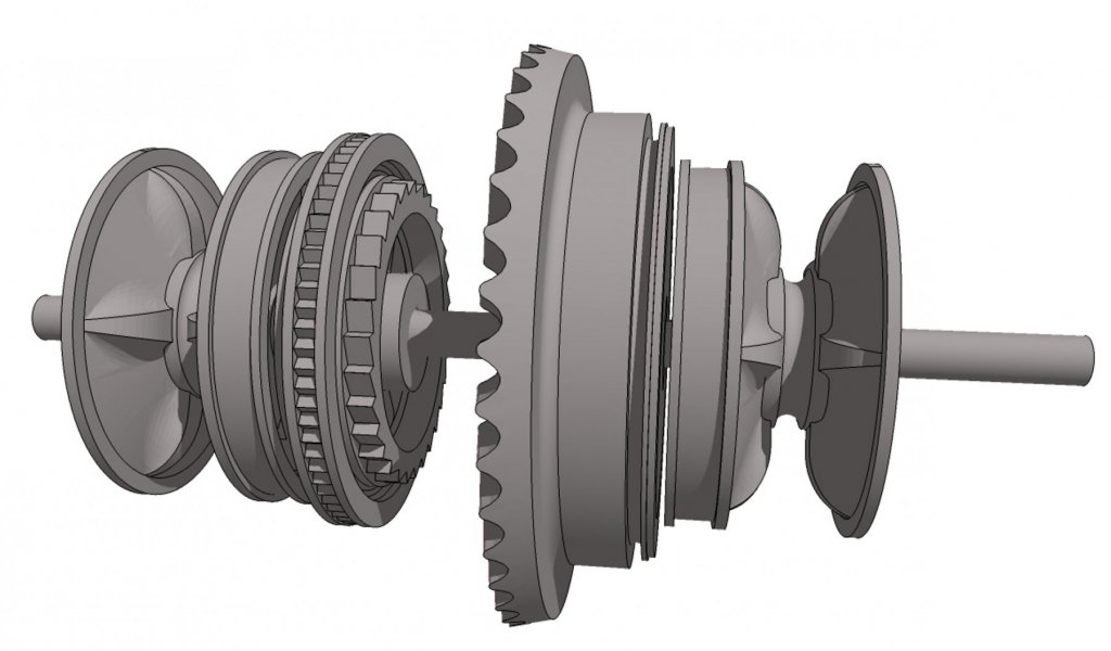
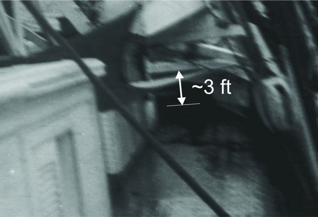
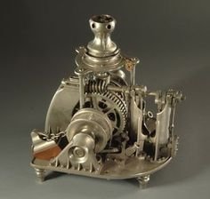
Bill, thank you for the link to that HWC catalog. It is my impression that, by 1917, Hyde had dropped their manual/hand-operated windlasses for all sorts of powered types, which are described in the catalog. During the transition period (probably around the time this ship was built), steam windlasses still had a capstan for motive power when steam wasn't available for some reason. That is why the capstan is geared into the windlass from a point above the unit, as shown in the brass model I posted above. Still, the book is an excellent reference, which I will definitely save. Roger, any windlass originally designed for operation by steam won't work for my purposes. Galilee was one of the last of the sail-only brigantines built on the West Coast for merchant service. She originally had a small steam donkey engine amidships for handling cargo and boats, but that was removed during the time my grandfather sailed in her. The crew operated the capstan/windlass by the traditional means—capstan bars and hard work! I'm pretty sure the windlass was operated from the capstan above. As the photo below shows, there was no room for the crew to operate the machinery for raising and lowering the anchors between decks. [Looking forward toward the forecastle on starboard side during heavy weather.] Photo courtesy of the Department of Terrestrial Magnetism, Carnegie Institution, Washington DC. Thanks again for your responses and interest. Terry
- 21 replies
-
- 2
-
-
- capstan
- hand windlass
- (and 3 more)
-
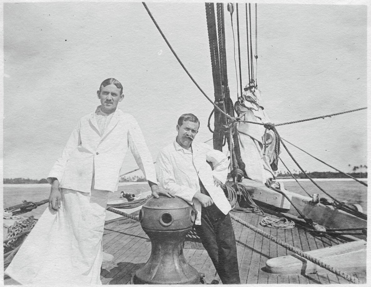
Hello, All. I've been searching for any plans/photos/schematics of a Hyde Windlass Company (HWC) hand capstan and windlass assembly. This would be sized for a 350-ton sailing merchant around 1890. The brigantine Galilee was launched in 1891 in California and seems to have been equipped with a Hyde capstan (see the photo below). Photo courtesy of the Department of Terrestrial Magnetism, Carnegie Institution, Washington DC (c. 1907) (The attire of the men is somewhat strange. The research crew's surgeon is on the right and his steward/surgical assistant is dressed for surgery.) What I really need is some information about the windlass, which was located in the open forecastle under the deck. I would like to render this equipment as accurately as possible, since it will be visible in the finished model. An entire windlass/capstan assembly has been modeled; its images are available on the Web. However, all that i have been able to find are steam windlasses, like the one shown here. Galilee's windlass was strictly manual. I have already contacted the Maine Maritime Museum in Bath, ME. They have some extensive archives pertaining to the HWC (which became the Bath Iron Works Shipyard), but their staff is limited and they haven't been able to find what I need so far. If any members live in or near Bath and would like to look into this, I would be very grateful. Terry

- 21 replies
-
- 2
-
-
- capstan
- hand windlass
- (and 3 more)
-
Floyd (fnkershner), I would be happy to provide some Sketchup coaching for your project at no charge. I am a retired professional educator and enjoy helping people learn new things. What you want to do utilizes just basic functions of Sketchup. Solid objects created in Sketchup are inherently manifold and 3D-printable unless you break the envelope or introduce extra geometry in an uncontrolled fashion. Please PM me with your email address if you are interested. Terry Colorado Springs, CO
-
question for sketchup users
CDR_Ret replied to hamilton's topic in CAD and 3D Modelling/Drafting Plans with Software
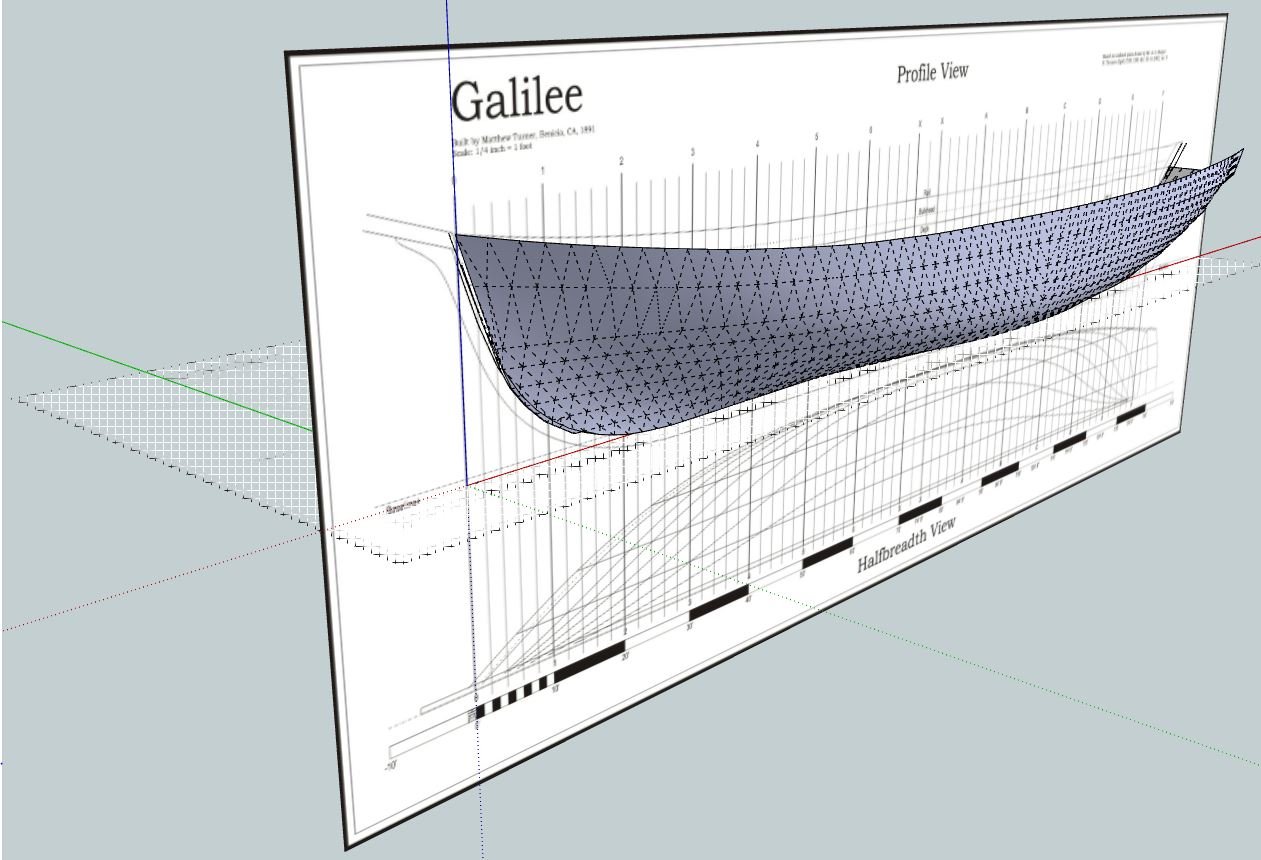
Here is a quick-and-dirty build of Galilee's hull I did in Sketchup a number of years ago using an old set of plans I developed back in 2002. Just wanted to see how it would work to display hull form. Unlike parametric 3D programs and for-the-purpose naval architectural software (e.g., DELFTShip), the result shows distinct polygons when you display hidden lines. It is also a lot of work creating the intersections at stations and waterlines. Terry
-
question for sketchup users
CDR_Ret replied to hamilton's topic in CAD and 3D Modelling/Drafting Plans with Software
Here is the instructional PDF for creating sockets in 3D objects. Please let me know if there is anything that is unclear, and I will try to explain it. A real power-user of Sketchup may be able to come up with a quicker method. I've been using Sketchup almost as long as it has been around, and I'm afraid I've become entrenched with some habits picked up years ago. Terry Creating the Hub of a Ship's Wheel.pdf -
question for sketchup users
CDR_Ret replied to hamilton's topic in CAD and 3D Modelling/Drafting Plans with Software
Sailor1–0, How familiar are you with the Intersection feature of Sketchup? You might want to try creating models of the wheel hub and spokes, individually grouping each element and arranging them as in the final object. (Save a copy of a spoke for later.) Then explode the hub and intersect the spokes with it to define the spoke cutouts in the hub. Regroup the hub, then explode the spokes. Intersect the hub with the spokes to define the spoke socket walls inside the hub. Delete all of the spoke components except for the parts that lie inside the hub. Explode the hub and delete the surface areas inside the spoke sockets. If the work is done carefully, the hub now is solid volume with the spoke sockets arranged where they need to be. If needed, recreate the spokes from the copy and insert them into the hub. The process is somewhat complicated but straightforward. I can provide a PDF with images of the key steps if that will help visualize the process. Terry -
Status update:
Finished house renovations—check
Sold house in Greenville, SC for nice profit—check
Loaded 26-foot Uhaul truck and drove 1500 miles to Colorado Springs, Colorado—check
Moved into a 1-bedroom apartment; temporarily stowed the rest of our stuff in two storage rooms—check
Sadly, there is no shop and all my tools are packed away. Will try to get back into working on my Galilee plans soon.
-
Update:
Bought a quaint two-story house in Colorado Springs, Colorado, USA with a 400-square foot (~37 m²) garage. The down side is that the garage has only one outlet and one light bulb (and a lot of remaining boxes).
As we get the painting and other move-in repairs accomplished, I will be taking time to rewire the garage so that I can actually do some work in it.
-
-
Late 19th Century Merchants: Antifouling Paint Over Copper?
CDR_Ret replied to CDR_Ret's topic in Nautical/Naval History
Thanks for the comments, guys. At the time the photos in post #1 were taken, the vessel's charter did not include entry into icebound waters, so no protection against ice floes was needed. The photos themselves don't show enough details of the hull covering to draw any firm conclusions. However, the photo of the Pitcairn in #8 shows the distinctive rectangular blotchy appearance associated with copper plating. The plates themselves are of about the same vertical dimensions as the linear marks in the #1 photos, so I am going copper plates. The darkness of the hull in the old B&W photos is likely due to the color response of the film in use at that time, which wasn't sensitive to the red end of the spectrum. -
DELFT SHIP
CDR_Ret replied to NavalArchAngel's topic in CAD and 3D Modelling/Drafting Plans with Software
Jud, Setting your vessel's length to the overall dimensions is a good way to avoid negative axial coordinates. My drawings of Galilee were all dimensioned starting with the aft perpendicular, so, to avoid remeasuring all the stations, I just went with negative X values at the transom. The program can handle them. It's a computer after all. Terry.- 15 replies
-
- 2
-
-
- delft ship
- 3dmodelling
- (and 1 more)
-
DELFT SHIP
CDR_Ret replied to NavalArchAngel's topic in CAD and 3D Modelling/Drafting Plans with Software
Here is a post I made a while back on getting started in DelfShip Free. These instructions were based on the program several versions ago, so some of them may be out of date. My biggest complaint to the company was that they don't clearly define the terms they used in their manual. An abbreviated DelftShip Offset Table glossary: X-coordinate—[Edited] distance forward from aft perpendicular. 0.0000 is the AP. Negative values are aft of the AP. [sorry about that. It's been over a year since I used the program. See the image from the DS manual below.] Y-coordinate—distance athwartships from the model centerline. 0.0000 is the centerline. Negative values appear on opposite side of the centerline from "face" of the hull. Z-coordinate—distance above the model baseline. For practical purposes, this should be at the height of the rabbet line for wooden ships. Making the baseline at the bottom of the keel really gets ugly unless you have a smooth, round-bottomed vessel. The "Draft" value should take this position into account. Waterline—self explanatory. Defined by a common Z-coordinate above the baseline at all stations. Station—self explanatory. Defined by a common X-coordinate at all waterlines or other longitudinal feature. Deck Line—defined by the highest X-coordinate at each station or other longitudinal feature. You can't have the "Deck Line" lower than the tops of the stations for this feature to work. Basically the moulded rail line in conventional drawings. Aft contour—the line defined by all the waterline/station points with a Y-coordinate of 0.0000 from the centerline at the aft end of the model. (It may also work for non-zero values if they define the distance of the rabbet line from the centerline. Never tried that.) Forward contour—the line defined by all the waterline points with a Y-coordinate of 0.0000 above the baseline at the forward end of the model. (Ditto as for "Aft Contour".) Flat of bottom—for flat-bottomed vessels like tankers, I think this tells the program to extend the bottom station Y-coordinate in the offset table to the centerline. Length—must agree with the Project Settings length (between perpendiculars) value. Beam—must agree with the Project Settings beam value. Draft—this is the setting that determines where the waterline is drawn on the hull above the baseline. It must agree with the Project Settings draft value. These are my best guesses, based on limited experience using the program. I recommend building the entire table in a spreadsheet, then exporting it as a plain ASCII text (.txt) file. Be aware that I had the best results by adding zeros in each column where there was no data. And you can't stick additional data between established waterlines to better define a sharp curve! Page 35 of the current manual (manual_809_296_mc0.pdf) shows the file architecture. Waterline data are arranged horizontally; station data are arranged vertically. Cheers!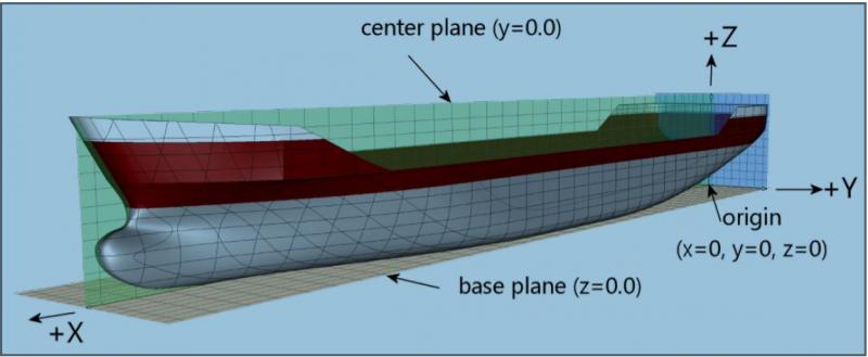
- 15 replies
-
- 2
-
-
- delft ship
- 3dmodelling
- (and 1 more)
-
Nuclear warships present a special problem as museums or for disposal. The reactor compartments retain radioactively contaminated systems, even after the nuclear fuel is removed, so containing the residual radioactivity and shielding the visitors from radiation is challenging. Sinking the ships presents the problem of releasing radioactivity to the environment, not to mention granting unrestricted access to classified hull construction technology to divers. To my knowledge, the only complete nuclear warship accessible by the public is the USS Nautilus (SSN 571) located at its museum in New London, Connecticut, USA. It required special radiation shields to be added outboard of the reactor compartment, and the engineering spaces are not accessible. All other decommissioned US nuclear submarines have been sent through the "ship and submarine recycling program," where the first step after removing usable equipment is to cut out the reactor compartment (and the missile compartment in the case of boomers) and weld the two halves together for towing to the recycling yard if applicable. The reactor compartments are sealed and transported to the storage facility at Hanford, WA. Fortunately, civic and military organizations have seen fit to preserve the sails of many important subs. Preserving the sails in lieu of the entire ship is a good compromise between economy and memorialization.: USS Nautilus (SSN 571)—Entire ship, New London, CT USS Triton (SSRN 586)—Sail, Richland, WA USS George Washington (SSBN 598)—Sail, New London, CT USS Woodrow Wilson (SSBN 624)—Bangor, WA USS Nathanael Greene (SSBN 636)—Sail, Port Canaveral, FL USS Sturgeon (SSN 637)—Sail, Keyport, WA USS Tautog (SSN-639)—Sail, Galveston, TX USS George Bancroft (SSBN-643)—Sail, Kings Bay, GA USS Lewis and Clark (SSBN 644)—Sail & rudder, Mount Pleasant, SC USS Grayling (SSN 646)—Sail, Portsmouth Naval Shipyard, Kittery, ME USS Mariano G. Vallejo (SSBN 658)—Sail, Mare Island, Vallejo, CA USS Hawkbill (SSN 666)–Sail, Arco, ID USS Parche (SSN 683)—Sail, Bremerton, WA USS Boston (SSN-703)—Sail & rudder, Buffalo, NY (This list may not be up to date) I am hoping that the last remaining Los Angeles-class boat, USS Bremerton (SSN 698), which I commissioned back in 1981, will be similarly preserved. She is currently homeported in Pearl Harbor, HI. As a matter of interest, the only US nuclear merchant, the NS Savannah, has been designated a National Historic Landmark, and is currently moored at Baltimore, MD, awaiting funding to permanently provide a memorial park for her.
-
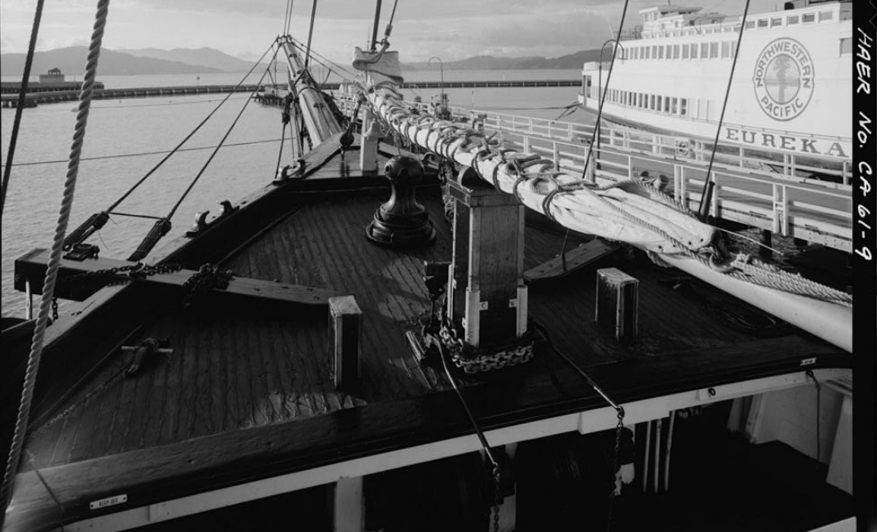
I checked out your site and it has great possibilities. Make sure you provide links to the ship Historic American Engineering Record (HAER) web pages at the Library of Congress and National Park Service. For example, here is the schooner C.A. Thayer's HAER page. Terry