CDR_Ret
-
Posts
660 -
Joined
-
Last visited
Content Type
Profiles
Forums
Gallery
Events
Everything posted by CDR_Ret
-

Novice builder and question re: Amati felucca
CDR_Ret replied to jrbm's topic in New member Introductions
Here is a set of felucca lines provided by the HAER small boat project CA-255: And here is an enlargement of the notes in this set of plans: Enjoy! Terry

-
Novice builder and question re: Amati felucca
CDR_Ret replied to jrbm's topic in New member Introductions
I'm not familiar with this vessel type. However, a weblink to a Facebook page provides 17 photos of these boats from San Francisco Bay and all of them show smoothly-fared bows into a stem piece. I'd say that flat-faced bow is incorrect. Terry -
In which offense is taken (or, "hey! I resemble that remark")
CDR_Ret replied to Cena's topic in New member Introductions
Like several others here, I built both Revell kits of the Constitution and the Cutty Sark when I was a mid-teen back in the '60s. Sadly, my father was still working for Link Aviation maintaining flight simulators at various air force bases around the US, so we tended to move around a lot. Poor planning on my part. The Constitution model got busted up on the move from Vermont to Ohio, and the Cutty Sark got busted up in the move from Ohio back to Vermont! I watched as the packer for the second move grabbed the ship by the bowsprit and lowered it into a bunch of wadded up paper for packing in the cardboard moving box. There wasn't much left at the other end . . . -
It might be helpful to provide a link to the relevant article in the OP of this topic. I'm not sure where to find it myself, never having created a build log!🤔
-
Heh, you can never trust submarine movies for dialog or technical accuracy. My family groans anytime we watched a submarine movie because I was always muttering, "That's not the way they do that," "that can't happen," or "that's an attack boat, not a boomer," etc. @CCClarke Terry
-
HMCSS Victoria 1855 by BANYAN - 1:72
CDR_Ret replied to BANYAN's topic in - Build logs for subjects built 1851 - 1900
Good news, Pat. I was wondering whether something had come up. Very glad that you received a clean bill of health. Don't push your recovery. The model will be there. Terry- 1,021 replies
-
- 2
-

-

-
- gun dispatch vessel
- victoria
- (and 2 more)
-
Starting in Rhino 8
CDR_Ret replied to GioMun's topic in CAD and 3D Modelling/Drafting Plans with Software
Not to mention that you actually have a head on your shoulders . . . ! -
I suspect that, rather than a "vacuum" causing the injury, it was the peak differential pressure of the shock wave caused by the ball's passage on soft tissues. The turbulent, low-pressure region associated with a high-speed projectile is directly behind the ball, so the "vacuum" itself would have little to do with causing the non-contact injury IMO.
-
Nate's PANDORA in 3D
CDR_Ret replied to 3DShipWright's topic in CAD and 3D Modelling/Drafting Plans with Software
Hey, Nate (@3DShipWright) and @Loracs. I got the alert that you had tagged me. There are three things to address in such a tutorial: The key steps required in constructing a ship hull and its details. Ship's hulls are not the simplest thing to build in Blender, requiring a lot of knowledge of what you are trying to model first, then translating that into building it in a digital 3D space, which leads to: Knowing how to use the gazillions of features to actually form the model in Blender, and then adding the really cool textures and materials that turn it into a photorealistic product. And (3), placing that model into a photorealistic environment. Sadly, this isn't like a cookbook, where you can start with nothing and end up with something in a linear fashion. The Blender knowledge space is like a 3D network itself, with nodes of prerequisite information connecting to other information. That's about the only way I can explain it. Also, the way you create an object can affect how to enhance it down the road I think it would worthwhile to attempt such a general tutorial for ship modelers, since it is pretty evident there is an interest for a segment of our community in creating such a guide. It would take a lot of effort on the parts of one or two people. If we could crowd source the project (with, perhaps a knowledgeable editor overseeing everything), that could make it more doable. (I did that in DELFTship a while back.) The downside to attempting such a tutorial is that Blender is updated frequently enough, it could make at least the details of using the program out of date fairly quickly. That's my two cents (American). Oh, wait, we aren't making pennies anymore . . . Terry -
Tapering Masts and Arms the easy way
CDR_Ret replied to Johnny Mike's topic in Masting, rigging and sails
Regarding mast tapers (and this applies to spars as well), applying the tables found in Underhill's book for the latter 1800s, you can see in this image that the individual masts are not "conical" tapers. They tend to gradually taper starting at the base then more quickly toward the heads. This is because the torque applied to any section of the mast is greater toward the base and least at the head. That torque on a mast also includes the forces applied by the mast(s) above it. So it makes sense that the mast diameter doesn't simply change proportionately with height. An extreme foreshortened view of the 1891 brigantine Galilee's combined fore topgallant-royal mast, showing the mast taper profiles for each section. Terry
-
That was true as well in our operational spaces on a submarine. Cupholders were provided near any flat surfaces. However, in the Wardroom and Crew's Mess at sea, tables were covered with Naugahyde, which was somewhat padded, so plates and cups didn't slide with rolls, and angles and dangles. Terry
- 493 replies
-
- 3
-
-
- minesweeper
- Cape
- (and 1 more)
-
Importing files into Delftship
CDR_Ret replied to woodartist's topic in CAD and 3D Modelling/Drafting Plans with Software
Hey, Julie, I think those are the files for my Background Images tutorial that I created back in 2022 when I was still primarily using DELFTship. The files can be found here in MSW. You are correct that the instructions are a bit dated, but the principles are still pretty much the same. Those instructions were created with reference to DELFTship v. 19.10 (328). The current program version is 17.30 (358). (Don't ask me how the version numbering system works . . .) The instructions are best for providing the steps for approaching a project. The D/S manual is and has been very weak on how to get into constructing a model. It tells you what each feature does, but very little on processes. Terry -
Starting in Rhino 8
CDR_Ret replied to GioMun's topic in CAD and 3D Modelling/Drafting Plans with Software
Hi, Giorgio. I'm with Julie on this topic. It's likely that someone proficient in Rhino would be able to eventually develop a nice hull, and then add on all the topside embellishments. However, trying to learn how to use a general-purpose 3D-CAD program like Rhino to create a hull comprised of surfaces varying in three dimensions, adhering to an existing set of basic plans, has proven to be challenging to a lot of folks attempting that. DELFTship, on the other hand, is a for-the-purpose naval architectural program with built-in features, like the three standard hull form views (sheer, halfbreadth, and body plans), along with features like "intersection" lines to show stations, waterlines, buttock lines, and diagonals—that all help in hull faring process. This is almost always needed because classic vessels were constructed from hand-drawn plans, and these plans, especially if they were developed before the advent of CAD, tend to lead to lack of fidelity among the standard views. In addition, DELFTship provides surface analysis tools that enhance the faring process, like Gaussian surfaces, that visually reveal bumps in the hull surface as well as providing local curvature analyses. The program is primarily used for hydrostatic and hydrodynamic analyses, but the structural features work well for simply modeling at any scale. One difficulty that most new DELFTship users have is what Julie mentioned—the surface mesh (called the control net) doesn't actually lie on a curved surface because of the mathematical way the program works, which is something you simply have to get used to. I suggest that you take a look at some of the reconstruction projects here in the various forums that utilized DELFTship to see how it presents. Like most 3D modeling programs, it has its own steep learning curve, but once you become familiar with it, the results are directly useful for developing plans of a vessel hull. Terry -
Late 19th or Early 20th Century Running Rigging
CDR_Ret replied to GrandpaPhil's topic in Masting, rigging and sails
Here's my two cents: My Galilee was an 1890s-vintage US-West Coast brigantine. As-built, her standing rigging was steel cable. For the DTM charter (1905--1908), her mast standing rigging was swapped for arctic-service hemp rope to reduce her magnetic signature. Photos of her prior-to and early into her DTM charter period showed rope running rigging throughout except for light chain sheets for the jibs. The foremast yard tye-lifts were of heavier chain, which were retained even during the DTM charter period. Some of the heavier service running rigging for the main boom, like pendants and lifts, may have been wire. Hard to tell from the photos. Hope this helps. Terry -
This is a recent BBC article about the Sutton Hoo ship, including a site photo.
-
Sadly, this just kicks the inevitable can down the road. Digital media also has a half life. The only way to perpetuate information in any medium is to recopy it before the reading-writing technology becomes obsolete. There is the story about a well-known ancient British history book (The Domesday Book) that was digitized in a proprietary format, involving an immense amount of time and resources. However, within just a few years the digital format became obsolete, negating all that work.
-
Wow, Julie, what an intro! You seem to be what they called a polymath in back in the day. If you need any assistance with getting started in DELFTship, I may be able to assist. It's very good for developing fare hydrostatic hull forms but it bogs down when creating lots of fine details. Terry
-
Beginner CAD recommendation
CDR_Ret replied to krith's topic in CAD and 3D Modelling/Drafting Plans with Software
You should visit the many threads in this CAD/3D Forum that address your question. For basic hull creation from plans, I believe that DELFTship Free will produce the most faired and smooth results. Then export the resulting model into other recommended programs to create the details. -
Those guys all look pretty buff!. Aren't there any striplings in your crew? 🙂
-
You might try these fixes: https://pdf.minitool.com/news/cant-download-pdf-files.html
-
And digital is even more forgiving and takes up zero space in the livingroom!😉 Terry
-
Nice! This configuration shows her several years after I left the boat. Terry
-
On submarines, we always slid down the main stairs between decks on the handrails with hands only. You controlled your speed with your grip. I even saw our COs do this on occasion! For vertical ladders, there were always hand grips positioned somewhere above the top rung to help the transition between ladder and the deck.
-
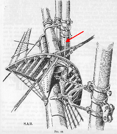
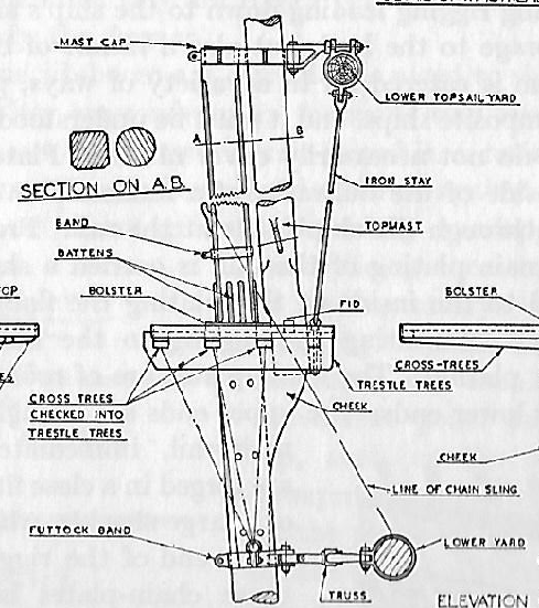
Hi Wefalck. Thanks for the pointer. In Underhill, Figure 44, there is indeed an image showing the lower topsail yard supporting rod/stay/strut. This is in the context of an iron and steel-sparred ship. The figure shows the upper end of the rod hinged to a hefty lug at the bottom of the center band, as stated earlier. The hinge plane was in line with the yard and vertical. The lower end of the rod terminated at the steel cross support at the base of the topmast. Scan from Figure 44, page 39, Masting and Rigging the Clipper Ship & Ocean Carrier, Harold A. Underhill, Reprint 1969; Brown, Son, and Ferguson, LTD Interestingly, all the diagrams of the LTS yard (including Fig. 44), show the LTS yard mainly supported by a swiveling crane arrangement, rather than the universal-jointed truss as in the lower yard (and as was the case for Galilee). So a crane plus a support rod for the LTS yard seems to be overkill except, perhaps, in larger ships. I finally found a side illustration of the LTS yard strut in Underhill, Plate 16, on page 80 (there is so much information buried in this book that it is easy to overlook things!). The plate illustration suggests that the lower end of the support strut is simply an eye-in-eye swivel, bolted through the forwardmost top platform crossbeam. So, lacking any other information, that's what I will go with. Plate No. 16, Ibid, showing the arrangement of the LTS yard support stay or strut. In Galilee's case, the entire weight of the LTS yard, hardware, rigging, and sail rests on this one rod! When the yard tilts, I'm still not sure how that motion is accommodated by this support system.🤔 Thanks for the prodding! Terry @wefalck @BANYAN